EP2144094A1 - Antiblendfilm, herstellungsprozess dafür und den film benutzende anzeigevorrichtung - Google Patents
Antiblendfilm, herstellungsprozess dafür und den film benutzende anzeigevorrichtung Download PDFInfo
- Publication number
- EP2144094A1 EP2144094A1 EP08752753A EP08752753A EP2144094A1 EP 2144094 A1 EP2144094 A1 EP 2144094A1 EP 08752753 A EP08752753 A EP 08752753A EP 08752753 A EP08752753 A EP 08752753A EP 2144094 A1 EP2144094 A1 EP 2144094A1
- Authority
- EP
- European Patent Office
- Prior art keywords
- fine particles
- glare
- mean diameter
- equal
- layer
- Prior art date
- Legal status (The legal status is an assumption and is not a legal conclusion. Google has not performed a legal analysis and makes no representation as to the accuracy of the status listed.)
- Withdrawn
Links
Images


Classifications
-
- G—PHYSICS
- G02—OPTICS
- G02B—OPTICAL ELEMENTS, SYSTEMS OR APPARATUS
- G02B5/00—Optical elements other than lenses
- G02B5/02—Diffusing elements; Afocal elements
-
- G—PHYSICS
- G02—OPTICS
- G02B—OPTICAL ELEMENTS, SYSTEMS OR APPARATUS
- G02B5/00—Optical elements other than lenses
- G02B5/02—Diffusing elements; Afocal elements
- G02B5/0273—Diffusing elements; Afocal elements characterized by the use
- G02B5/0278—Diffusing elements; Afocal elements characterized by the use used in transmission
-
- B—PERFORMING OPERATIONS; TRANSPORTING
- B32—LAYERED PRODUCTS
- B32B—LAYERED PRODUCTS, i.e. PRODUCTS BUILT-UP OF STRATA OF FLAT OR NON-FLAT, e.g. CELLULAR OR HONEYCOMB, FORM
- B32B27/00—Layered products comprising a layer of synthetic resin
- B32B27/18—Layered products comprising a layer of synthetic resin characterised by the use of special additives
- B32B27/20—Layered products comprising a layer of synthetic resin characterised by the use of special additives using fillers, pigments, thixotroping agents
-
- G—PHYSICS
- G02—OPTICS
- G02B—OPTICAL ELEMENTS, SYSTEMS OR APPARATUS
- G02B5/00—Optical elements other than lenses
- G02B5/02—Diffusing elements; Afocal elements
- G02B5/0205—Diffusing elements; Afocal elements characterised by the diffusing properties
- G02B5/021—Diffusing elements; Afocal elements characterised by the diffusing properties the diffusion taking place at the element's surface, e.g. by means of surface roughening or microprismatic structures
- G02B5/0226—Diffusing elements; Afocal elements characterised by the diffusing properties the diffusion taking place at the element's surface, e.g. by means of surface roughening or microprismatic structures having particles on the surface
-
- G—PHYSICS
- G02—OPTICS
- G02F—OPTICAL DEVICES OR ARRANGEMENTS FOR THE CONTROL OF LIGHT BY MODIFICATION OF THE OPTICAL PROPERTIES OF THE MEDIA OF THE ELEMENTS INVOLVED THEREIN; NON-LINEAR OPTICS; FREQUENCY-CHANGING OF LIGHT; OPTICAL LOGIC ELEMENTS; OPTICAL ANALOGUE/DIGITAL CONVERTERS
- G02F1/00—Devices or arrangements for the control of the intensity, colour, phase, polarisation or direction of light arriving from an independent light source, e.g. switching, gating or modulating; Non-linear optics
- G02F1/01—Devices or arrangements for the control of the intensity, colour, phase, polarisation or direction of light arriving from an independent light source, e.g. switching, gating or modulating; Non-linear optics for the control of the intensity, phase, polarisation or colour
- G02F1/13—Devices or arrangements for the control of the intensity, colour, phase, polarisation or direction of light arriving from an independent light source, e.g. switching, gating or modulating; Non-linear optics for the control of the intensity, phase, polarisation or colour based on liquid crystals, e.g. single liquid crystal display cells
- G02F1/133—Constructional arrangements; Operation of liquid crystal cells; Circuit arrangements
- G02F1/1333—Constructional arrangements; Manufacturing methods
- G02F1/1335—Structural association of cells with optical devices, e.g. polarisers or reflectors
- G02F1/133502—Antiglare, refractive index matching layers
-
- Y—GENERAL TAGGING OF NEW TECHNOLOGICAL DEVELOPMENTS; GENERAL TAGGING OF CROSS-SECTIONAL TECHNOLOGIES SPANNING OVER SEVERAL SECTIONS OF THE IPC; TECHNICAL SUBJECTS COVERED BY FORMER USPC CROSS-REFERENCE ART COLLECTIONS [XRACs] AND DIGESTS
- Y10—TECHNICAL SUBJECTS COVERED BY FORMER USPC
- Y10T—TECHNICAL SUBJECTS COVERED BY FORMER US CLASSIFICATION
- Y10T428/00—Stock material or miscellaneous articles
- Y10T428/24—Structurally defined web or sheet [e.g., overall dimension, etc.]
- Y10T428/24355—Continuous and nonuniform or irregular surface on layer or component [e.g., roofing, etc.]
- Y10T428/24372—Particulate matter
-
- Y—GENERAL TAGGING OF NEW TECHNOLOGICAL DEVELOPMENTS; GENERAL TAGGING OF CROSS-SECTIONAL TECHNOLOGIES SPANNING OVER SEVERAL SECTIONS OF THE IPC; TECHNICAL SUBJECTS COVERED BY FORMER USPC CROSS-REFERENCE ART COLLECTIONS [XRACs] AND DIGESTS
- Y10—TECHNICAL SUBJECTS COVERED BY FORMER USPC
- Y10T—TECHNICAL SUBJECTS COVERED BY FORMER US CLASSIFICATION
- Y10T428/00—Stock material or miscellaneous articles
- Y10T428/24—Structurally defined web or sheet [e.g., overall dimension, etc.]
- Y10T428/24479—Structurally defined web or sheet [e.g., overall dimension, etc.] including variation in thickness
- Y10T428/24521—Structurally defined web or sheet [e.g., overall dimension, etc.] including variation in thickness with component conforming to contour of nonplanar surface
-
- Y—GENERAL TAGGING OF NEW TECHNOLOGICAL DEVELOPMENTS; GENERAL TAGGING OF CROSS-SECTIONAL TECHNOLOGIES SPANNING OVER SEVERAL SECTIONS OF THE IPC; TECHNICAL SUBJECTS COVERED BY FORMER USPC CROSS-REFERENCE ART COLLECTIONS [XRACs] AND DIGESTS
- Y10—TECHNICAL SUBJECTS COVERED BY FORMER USPC
- Y10T—TECHNICAL SUBJECTS COVERED BY FORMER US CLASSIFICATION
- Y10T428/00—Stock material or miscellaneous articles
- Y10T428/24—Structurally defined web or sheet [e.g., overall dimension, etc.]
- Y10T428/24479—Structurally defined web or sheet [e.g., overall dimension, etc.] including variation in thickness
- Y10T428/24595—Structurally defined web or sheet [e.g., overall dimension, etc.] including variation in thickness and varying density
-
- Y—GENERAL TAGGING OF NEW TECHNOLOGICAL DEVELOPMENTS; GENERAL TAGGING OF CROSS-SECTIONAL TECHNOLOGIES SPANNING OVER SEVERAL SECTIONS OF THE IPC; TECHNICAL SUBJECTS COVERED BY FORMER USPC CROSS-REFERENCE ART COLLECTIONS [XRACs] AND DIGESTS
- Y10—TECHNICAL SUBJECTS COVERED BY FORMER USPC
- Y10T—TECHNICAL SUBJECTS COVERED BY FORMER US CLASSIFICATION
- Y10T428/00—Stock material or miscellaneous articles
- Y10T428/25—Web or sheet containing structurally defined element or component and including a second component containing structurally defined particles
Definitions
- the invention relates to an anti-glare film, a method of manufacturing the same, and a display apparatus using the same. More particularly, the invention relates to an anti-glare film which is used for surfaces of various display apparatuses such as a liquid crystal display, a plasma display, a rear projection type display, an electroluminescence display, and a CRT (Cathode Ray Tube) display and relates to a method of manufacturing the same and a display apparatus using the same.
- various display apparatuses such as a liquid crystal display, a plasma display, a rear projection type display, an electroluminescence display, and a CRT (Cathode Ray Tube) display and relates to a method of manufacturing the same and a display apparatus using the same.
- the method whereby the anti-glare film having the micro concave/convex portions on the surface is used and the reflected image is blurred by the diffuse reflection is widely used because it is reasonable and high productivity is obtained.
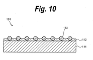
- the anti-glare film 101 has: a substrate 111; and an anti-glare layer 112 formed on the substrate 111.
- the anti-glare layer 112 is formed by a resin containing fine particles 113 made of irregular silica or resin beads. By projecting the fine particles 113 from the surface of the anti-glare layer 112, micro concave/convex shapes are formed on the surface.
- the anti-glare film 101 is formed by coating the substrate 111 with a coating material containing the fine particles 113, a resin, a solvent, and the like and drying the coating material. According to the anti-glare film 101 having the constructionmentioned above, since light which enters the anti-glare layer 112 is scattered by the fine particles 113 projected from the anti-glare layer 112, a reflected image due to the surface reflection is blurred.
- the anti-glare film 101 since the concave/convex portions are formed on the surface by the projecting shape of each fine particle 113, there is such a problem that a haze value rises due to the projections of those fine particles 113, an image becomes whitish, and particularly, in the case where the external light is strong, a contrast decreases, visibility deteriorates, and image visibility also deteriorates.
- an object of the invention to provide an anti-glare film which can satisfy both anti-glare property and a contrast and to provide a method of manufacturing the same and a display apparatus using the same.
- the present inventors have vigorously made researches in order to solve the foregoing problems, so that they have found out a point that instead of the light scattering due to the projection of each fine particle projecting from the surface of an anti-glare layer, a Marangoni convection due to uneven distribution (surface tension variation) of the surface tension which is generated at the time of volatilization of a solvent contained in a coating material is used, the fine particles are properly aggregated by the convection which is caused in the coating material, a Benard cell structure is formed on the surface, and gentle wavy micro concave/convex shapes are formed onto the anti-glare layer surface by meniscuses of the liquid resin formed in the Benard cells, so that an anti-glare film which can satisfy both an anti-glare property and a contrast can be obtained.
- the anti-glare film containing the fine particles having the relatively wide particle size distribution since the fine particles of large diameters projecting largely from the anti-glare layer surface exist and, further, their existence frequency is small, there occurs such a problem that the large-sized particles are visually perceived like a foreign matter defect (matter defect) on the anti-glare layer surface and, particularly, when the external light is reflected onto the surface, the film surface is seen like a rough surface.
- the present inventors have further vigorously made researches, so that they have found out an anti-glare film in which by controlling the particle size distribution of the fine particles, an existence probability of the large-sized particles, and a film thickness of the anti-glare layer, the rough surface defect due to the large-sized particles is reduced while satisfying both of the anti-glare property and the contrast.
- the invention has been derived on the basis of the above examinations.
- an anti-glare film comprising:
- an anti-glare film comprising the steps of:
- a display apparatus comprising:
- an anti-glare film comprising:
- an anti-glare film comprising the steps of:
- a display apparatus comprising:
- an anti-glare film comprising:
- an anti-glare film comprising the steps of:
- a display apparatus comprising:
- the appearance of white muddiness can be suppressed while dispersing the light.
- the projection of the large-sized particles from the anti-glare layer surface can be reduced.
- the anti-glare film having the excellent contrast while having the anti-glare property can be obtained.
- the large-sized particles are not visually perceived as matter defects on the anti-glare layer surface and the rough surface appearance can be improved. Therefore, the display apparatus using such an anti-glare film can realize the excellent visibility.
- Fig. 1 shows an example of a construction of a liquid crystal display apparatus according to the first embodiment of the invention.
- the liquid crystal display apparatus has a liquid crystal panel 2 and a light source 3 provided just under the liquid crystal panel 2.
- the liquid crystal panel 2 has an anti-glare film 1 on its display screen side.
- the light source 3 is used to supply light to a liquid crystal panel 4 and has, for example, a fluorescent lamp (FL), an EL (Electro Luminescence), an LED (Light Emitting Diode), or the like.
- the liquid crystal panel 2 is used to time-dependently and spatially modulate the light supplied from the light source 3 and display information.
- Polarizer sheets 2a and 2b are provided on both surfaces of the liquid crystal panel 2. Each of the polarizer sheets 2a and 2b allows only one of the polarization components which cross perpendicularly in the incident light to pass and shields the other polarization component by absorption.
- the polarizer sheets 2a and 2b are arranged so that, for example, transmission axes cross mutually perpendicularly.
- Fig. 2 shows an example of a construction of the anti-glare film 1 according to the first embodiment of the invention.
- the anti-glare film 1 has: a substrate 11; and an anti-glare layer 12 formed on the substrate 11.
- the anti-glare layer 12 contains fine particles 13. Benard cells are formed on the surface of the anti-glare layer 12 by a convection which is caused in a coating material in a drying step of the coating material and micro concave/convex shapes formed by a proper aggregation or the like of the fine particles 13 are formed on the surface.
- An outer haze is preferably equal to or less than 5% and, much preferably, is equal to or less than 3%. If the outer haze is equal to or less than 5%, an appearance of white muddiness decreases. If it is equal to or less than 3%, the appearance of white muddiness is hardly perceived.
- the outer haze indicates a value at the time when the surface scattering is detected. The higher the outer haze is, the more the white muddiness increases.
- the degree of white muddiness is preferably equal to or less than 2.0, much preferably, lies within a range from 0.5 to 1.5. If the degree of white muddiness is equal to or less than 2.0, a decrease in contrast can be suppressed. If it is equal to or less than 1.5, the excellent contrast can be realized.
- a plastic film having transparency can be used.
- a transparent plastic film for example, a well-known high polymer film can be used.
- a well-known high polymer film specifically speaking, for example, triacetyl cellulose (TAC), polyester (TPEE), polyethylene terephthalate (PET), polyimide (PI), polyamide (PA), aramid, polyethylene (PE), polyacrylate (PAR), polyether sulfone, polysulfone, diacetyl cellulose, polypropylene (PP), polyvinyl chloride, an acrylic resin (PMMA), polycarbonate (PC), an epoxy resin, a urea resin, an urethane resin, a melamine resin, or the like can be mentioned.
- a thickness of substrate 11 preferably lies within a range from 38 ⁇ m to 100 ⁇ m from a viewpoint of productivity, it is not particularly limited to such a range.
- An average film thickness of anti-glare layer 12 preferably lies within a range from 3 to 30 ⁇ m, much preferably, a range from 4 to 15 ⁇ m. This is because if the film thickness is less than 3 ⁇ m, it is difficult to obtain a desired hardness, and if it is larger than 30 ⁇ m, there is a case where the resin is curled in the step of curing the resin upon manufacturing.
- the film thickness of anti-glare layer 12 is adjusted in accordance with the mean diameter of the fine particles 13 which are used.
- the film thickness is preferably equal to or larger than the mean diameter of the fine particles 13 and is equal to or less than three times as large as the mean diameter of the fine particles 13, much preferably, is equal to or larger than 1.5 times as large as the mean diameter and is equal to or less than three times as large as the mean diameter of the fine particles 13. If the film thickness is less than the mean diameter of the fine particles 13, there is such a tendency that the degree of white muddiness rises and the matter defect occurs on the surface. If the film thickness exceeds three times as large as the mean diameter of the fine particles 13, there is a case where the resin is curled during the step of curing the resin upon manufacturing.
- the film thickness of anti-glare layer 12 denotes the average film thickness of the anti-glare layer 12.
- the film thickness of anti-glare layer 12 can be obtained by observing a cross section obtained by cutting the anti-glare film 1 by an SEM (scanning electron microscope) and measuring a thickness of binder portion of the anti-glare layer 12.
- SEM scanning electron microscope
- the thickness obtained by a method of subtracting an arithmetic mean roughness Ra of the anti-glare layer 12 from the thickness of the whole anti-glare layer 12 containing the fine particles 13 which has been measured by using a Thickness Measuring Instrument (manufacturedbyTESACo.,Ltd.) almost coincides with the thickness of binder portion which has been measured by the SEM observation, such a method may be used.
- the numerical value range of the film thickness of anti-glare layer 12 has been obtained by the latter measuring method in the foregoing measuring methods.
- the micro concave/convex shapes are formed on the surface of the anti-glare layer 12.
- the micro concave/convex shapes differ from the concave/convex shapes formed when each fine particle 13 is projected from the anti-glare layer 12 as in the conventional manner and it is preferable to form the micro concave/convex shapes on the surface of the anti-glare layer 12, for example, by setting an aggregate of the fine particles 13 in which the fine particles 13 have properly been aggregated in the in-plane direction to one convex portion.
- the surface of the anti-glare layer 12 becomes the gentle micro concave/convex shapes of a long cycle and both of the contrast and the anti-glare property can be satisfied.
- the fine particles 13 are not extremely projected from the anti-glare layer 12 and the surfaces of the fine particles 13 are not extremely exposed. This is because if the surfaces of the fine particles 13 are extremely exposed, the micro concave/convex shapes containing steep angle components are formed by steep inclined portions of the fine particles 13 and the light is diffused at a wide angle, so that the display screen becomes a white muddiness. Much preferably, it is preferable that the surfaces of the fine particles 13 are not exposed. By suppressing the exposure of the fine particles 13, the micro concave/convex shapes containing the steep angle component are not formed. Therefore, the wide-angle scattering decreases and the white muddiness can be further suppressed.
- a fine particle 13 for example, a spherical or flat inorganic fine particle or organic fine particle or the like is used.
- the mean diameter of fine particles 13 preferably lies within a range from about 5 nm to about 15 ⁇ m, much preferably, a range from 1 ⁇ m to 10 ⁇ m, and further preferably, a range from 1.5 ⁇ m to 7.5 ⁇ m. This is because if the mean diameter is less than 5 nm, the surface roughness of the anti-glare layer 12 becomes too fine and the anti-glare property is poor, and if it is larger than 15 ⁇ m, the film thickness of anti-glare layer 12 becomes thick, so that there is a case where the resin is curled in the step of curing the resin upon manufacturing.
- the mean diameter of the fine particles 13 can be measured by, for example, a dynamic light scattering method, a laser diffracting method, a centrifugal sedimentation method, an FFF (Field Flow Fractionation) method, a pore electric resistance method, or the like.
- the numerical value range of the mean diameter of the fine particles 13 has been obtained by the pore electric resistance method in the foregoing measuring methods.
- organic fine particles for example, the fine particle made of an acrylic resin (PMMA), styrene (PS), an acryl-styrene copolymer, a melamine resin, polycarbonate (PC), or the like can be used.
- the organic fine particle is not particularly limited to a cross-link, an uncross-link, or the like but any organic fine particle made of plastics or the like can be used.
- beads of a low polarity In order to properly cause a convection which occurs in the coating material upon manufacturing and an aggregation of the fine particles 13 and to form desired micro concave/convex shapes onto the surface of the anti-glare layer 12, it is preferable to use beads of a low polarity.
- the fine particles 13 having a small polarity such as, for example, an acrylic resin or the like are used as fine particles 13, the convection in the coating material which occurs upon manufacturing and the aggregation of the fine particles 13 decrease slightly. Therefore, it is much preferable to use the non-polar fine particles 13 such as, for example, styrene or the like.
- the fine particles 13 whose polarity has been adjusted like an acryl-styrene copolymer may be used. This is because the anti-glare property of the anti-glare layer 11 can be further improved by such fine particles.
- inorganic fine particles for example, regular silica, alumina, or the like can be used. It is preferable to make the surfaces of the inorganic fine particles non-polar by an organic process. This is because the convection and the aggregation of the fine particles 13 occur properly and desired Benard cells are formed.
- the continuous gentle wavy micro concave/convex shapes can be formed onto the surface of the anti-glare layer 12, so that a degree of white muddiness can be reduced while maintaining the anti-glare property.
- ridge line portions between the convex portions which are formed by the proper aggregation of the fine particles 13 can be continuously formed.
- the fluctuation coefficient of the particle size distribution indicates a value of the fluctuation coefficient of the particle size distribution of the fine particles 13 obtained after the classifying process was executed.
- the large-sizedparticles can be classified and removed by using a filter.
- the number of large-sized particles which are choked to the filter increases and a choke occurs, so that distribution itself of the small-sized particles also changes. It is, therefore, necessary to select the method of the classifying process and the number of times thereof in accordance with desired classification precision.
- a gravity classifier an inertia classifier, a centrifugal classifier, a cyclone, an air separator, a micron separator, Microplex, Multiplex, a zigzag classifier, Accucut, a conical separator, a turbo classifier, a super separator, a dispersion separator, Elbow-Jet, a fluidized bed classifier, a virtual impactor, O-Sepa, a vibrating screen, a shifter (" Handbook of powder engineering” edited by The Society of Powder Technology, The Nikkan Kogyo Simbun Ltd., p514 (1986 )), and the like.
- the particle sizes which are classified differ depending on the film thickness of anti-glare film 1 and a target surface roughness shape. To reduce the matter defects caused by the large-sized particles on the surface of the anti-glare layer 12, since a relation between the particle sizes of the fine particles 13 and the thickness of anti-glare layer 12 is important, it is necessary to properly control such a relation.
- the large-sized particles which are equal to or larger than twice as large as the thickness of anti-glare layer 12 are classified and removed, thereby deriving the fine particles 13 in which the fine particles 13 having the particle sizes which are equal to or larger than twice as large as the thickness of anti-glare layer 12 are not substantially contained, much preferably, deriving the fine particles 13 in which the fine particles 13 having the particle sizes which are equal to or larger than 1.6 times as large as the thickness of anti-glare layer 12 are not substantially contained.
- the matter defects are reduced and the anti-glare film 1 having the smooth surface can be obtained.
- the fine particles substantially containing the fine particles 13 having the particle sizes less than twice as large as the thickness of anti-glare layer 12 much preferably, the fine particles substantially containing the fine particles 13 having the particle sizes less than 1.6 times as large as the thickness of anti-glare layer 12, the matter defects are reduced and the anti-glare film 1 having the smooth surface can be obtained.
- the large-sized particles are not substantially contained denotes not only a case where the large-sized particles are not contained at all but also a case where a small number of large-sized particles are contained to such a certain extent that quality is not deteriorated within a range where the a rough surface appearance is not particularly perceived on the surface of the anti-glare layer 12 due to the matter defects which are formed by the large-sized particles. It is preferable to set a ratio of the large-sized particles to, for example, 0.1% or less in the fine particles 13.
- the fine particles 13 by setting the number of fine particles having the particle sizes which are equal to or larger than twice as large as the mean diameter to 2% or less, much preferably, 1% or less, and further preferably, 0.5% or less and by setting the thickness of anti-glare layer 12 to a value which is equal to or larger than the mean diameter, much preferably, a value which is equal to or larger than 1. 5 times as large as the mean diameter, the matter defects are reduced and the anti-glare film 1 having the smooth surface can be obtained.
- the thickness of anti-glare layer 12 is set to a value which is equal to or larger than the mean diameter, much preferably, a value which is equal to or larger than 1.5 times as large as the mean diameter.
- the thickness of anti-glare layer 12 is set to a value which is equal to or larger than the mean diameter, much preferably, a value which is equal to or larger than 1.5 times as large as the mean diameter.
- the anti-glare film 1 in which the matters are not visually perceived and which has the smooth surface can be obtained.
- the medium particle size denotes a particle size at the time when the number of or a mass of fine particles larger than a certain particle size occupies 50% of that of the whole powder in particle size distribution of the powder.
- Fig. 3 is a diagram showing particle size distribution of fine particles d1, fine particles d2, and fine particles d3 each having different particle size distribution and their total distribution. In the example shown in Fig.
- the anti-glare film 1 having the smooth surface in which there are no matters can be obtained.
- the anti-glare film 1 according to the first embodiment does not have the local projections of the fine particles 13 but has the continuous gentle wavy micro concave/convex shapes on the surface of the anti-glare layer 12. Therefore, the anti-glare film 1 in which while maintaining the anti-glare property, a phenomenon in which the light is diffused at a wide angle is suppressed, a phenomenon in which the display screen becomes a white muddiness can be reduced, and a rough surface appearance due to the matter defects is small can be realized.
- the substrate 11 is coated with a coating material containing the fine particles 13, a resin, and a solvent, the fine particles 13 are properly aggregated in the in-plane direction by a convection which occurs in the step of drying the solvent, Benard cells are formed on the surface of the coating film, and thereafter, they are cured.
- the resin, the foregoing fine particles 13, and the solvent are mixed by a stirrer such as a disper or the like or a disperser such as a beads mill or the like, thereby obtaining the coating material in which the fine particles 13 have been dispersed.
- a light stabilizer, an ultraviolet absorbent, an antistatic agent, a flame resistance, an oxidation inhibitor, or the like may be further added as necessary.
- Silica fine particles or the like may be further added as a viscosity adjuster.
- a solvent for example, an organic solvent which dissolves a resin raw material that is used, has good wettability with the fine particles 13, and does not bleach the substrate 11 or the like can be used. It is preferable to use the solvent whose surface tension is equal to or less than 23 mN/m at a coating temperature. This is because the Benard cells can be moderately formed at the time of drying the coating material and the gentle waviness can be obtained on the surface of the anti-glare layer 12. If the surface tension exceeds the above range, the aggregation of the fine particles 13 becomes hard and the concave/convex portions which are formed on the surface of the anti-glare layer 12 enlarge.
- the surface becomes a white muddiness and the surface becomes glossy.
- an organic solvent for example, tertiary butanol whose surface tension is equal to 20.0 mN/m at an environmental temperature of 20 °C, isopropyl acetate of 22.1 mN/m under an environmental condition of 22 °C, or the like can be mentioned.
- the invention is not particularly limited to those materials so long as the above requirements are satisfied.
- the surface tension of the solvent can be calculated by, for example, a wilhelmy method whereby a wilhelmy sheet and a liquid sample are come into contact with each other, a distortion is applied, and a force adapted to pull the wilhelmy sheet into the liquid is measured.
- a measuring apparatus for example, RHEOSURF as a dynamic surface tension measuring apparatus manufactured by UBM Co., Ltd. can be used.
- a resin for example, an ionizing radiation curing type resin which is cured by an ultraviolet ray or an electron beam or a thermosetting resin which is cured by heat is preferable from a viewpoint of easiness of manufacturing, and a photosensitive resin which can be cured by an ultraviolet ray is most preferable.
- a photosensitive resin for example, an acrylate system resin such as urethane acrylate, epoxy acrylate, polyester acrylate, polyol acrylate, polyether acrylate, or melamine acrylate can be used.
- a photosensitive resin having an excellent translucent property is particularly preferable from a viewpoint of an image permeability
- a photosensitive resin having a high hardness is preferable from a viewpoint of a damage resistance, and one of them can be properly selected.
- the ionizing radiation curing type resin is not particularly limited to an ultraviolet curing type resin. Although any resin can be used so long as it has the translucent property, a resin in which a hue of the transmitted light and a transmitted light amount are not remarkably changed by coloring and haze is preferable.
- Such a photosensitive resin is obtained by mixing a photopolymerization initiator into an organic material such as monomer, oligomer, or polymer which can form the resin.
- the urethane acrylate resin is obtained by allowing an isocyanate monomer or prepolymer to react to polyester polyol and by allowing a monomer of an acrylate or methacrylate system having a hydroxyl group to react to an obtained product.
- a monomer, oligomer, and polymer which can form the resin it is preferable to use at least one kind of monomer, oligomer, and polymer which are liquids even if they are dried.
- a monomer, oligomer, and polymer which are liquids even if they are dried it is preferable to use a material having a nature of a relatively high viscosity in which even after it was dried, a Benard cell structure is maintained on the surface of the coating material and meniscuses due to the resin liquid can be formed in the Benard cells. This is because even after the coating film was dried, the gentle concave/convex shapes can be held on the surface.
- a photopolymerization initiator contained in the photosensitive resin for example, a benzophenone derivative, an acetophenone derivative, an anthraquinone derivative, or the like can be used solely or in combination.
- a component which enables a coating film to be more preferably formed, for example, an acrylic resin or the like may be further properly selectively mixed into the photosensitive resin.
- the substrate 11 is coated with the coating material obtained as mentioned above. It is coated with the coating material so that an average film thickness after the drying is equal to, preferably, 3 to 30 ⁇ m, much preferably, 4 to 15 ⁇ m.
- the film thickness is properly adjusted in accordance with the particle size of the fine particles 13. There is a case where when the film thickness is smaller than such a numerical value range, it is difficult to obtain a desired hardness, and when the film thickness is larger than such a numerical value range, the resin is largely curled at the time of curing of the resin.
- the coating method is not particularly limited but a well-known coating method can be used.
- a gravure coater for example, a bar coater, a die coater, a knife coater, a comma coater, a spray coater, a curtain coater, or the like can be mentioned.
- the coating method is not limited to them but any method may be used so long as a thickness of a predetermined amount can be uniformly coated.
- the solvent is volatilized.
- a Marangoni convection due to uneven distribution of the surface tension occurring at the time of volatilization of the solvent is used, a collision and an aggregation of the fine particles 13 are properly caused by the convection in the coating material, and a Benard cell structure is formed on the surface of the coating layer.
- the fine particles 13 have wide particle size distribution, for example, as the convection in the coating material progresses, first, the motions of the fine particles 13 having relatively large particle sizes decrease.
- the fine particles 13 having relatively small particle sizes are properly aggregated in the in-plane direction in the fine particles 13 having the relatively large particle sizes, convex portions are formed, and the gentle micro concave/convex shapes having a long cycle are formed on the surface. Since the fine particles 13 having the relatively small particle sizes exist so as to fill spaces among the fine particles 13 having the relatively large particle sizes, ridge line portions between the convex portions are continuously formed.
- a relation between a polarity of the fine particles 13 and the surface tension of the solvent exercises an influence on a step of forming the Benard cell structure by properly causing the convection in the coating material.
- the gentle wavy micro concave/convex portions are formed onto the surface of the coating film by the meniscuses of the liquid resin formed in the Benard cells.
- the resin which is liquid until it is cured even after the drying step it is preferable to use the resin which is liquid until it is cured even after the drying step. This is because even if the layer is dried, the gentle waviness of the surface can be held. It is considered that in the case of containing the dry curing resin serving as a solid after the drying, since the substrate 11 is flat, the surface of the anti-glare layer 12 formed on the substrate 11 is flattened by the initial drying, and even after the layer was perfectly dried up to the inside thereof through the drying step, it is flattened according to the substrate 11.
- a drying condition is not particularly limited but the layer may be dried by a natural drying or can be also artificially dried by adjusting a drying temperature, a drying time, and the like.
- a drying temperature for example, in the case of blowing a wind upon drying, it is necessary to pay attention so that no wind-wrought patterns are caused on the coating layer surface. This is because desired gentle wavy concave/convex shapes cannot be obtained on the surface of the anti-glare layer 12 and both of the anti-glare property and the contrast cannot be satisfied.
- the drying temperature and the drying time can be properly decided by a boiling point of the solvent contained in the coating material.
- the drying temperature and the drying time are selected within such a range where a deformation of the substrate is not caused by a heat contraction.
- the Benard cells which are caused at the time of drying incorporate not only the cells which are formed when the layer is purposely dried by the drying step but also the cells which are formed since the solvent is volatilized in a state where, for example, the coating film is left in order to flatten it after the coating.
- the anti-glare layer 12 After drying, by curing the ionizing radiation curable type resin, the anti-glare layer 12 is formed.
- the ultraviolet ray is preferable from a viewpoint of producing facilities.
- the ultraviolet ray source is not particularly limited but a high pressure mercury lamp, a metal halide lamp, or the like is properly used.
- a cumulative irradiation amount a cumulative irradiation amount of such an extent that the curing of the resin which is used and after-yellowing of the resin and the substrate 11 do not occur can be properly selected.
- An atmosphere of the irradiation can be properly selected in accordance with a degree of the resin curing.
- the irradiation can be performed in the air or an inert atmosphere such as nitrogen or argon.
- the resin is solidified in a state where the Benard cells have been formed and the anti-glare layer 12 having the gentle concave/convex shapes on the surface is formed.
- the surface of the anti-glare layer 12 becomes the gentle wavy micro concave/convex shapes.
- the matter defects can be reduced by removing the large-sized particles contained in the fine particles 13. Therefore, the anti-glare film 1 which has the high contrast, the excellent anti-glare property, and further, in which the rough surface appearance is small can be realized.
- the anti-glare film 1 for the liquid crystal display apparatus, the visibility of the image which is displayed on the liquid crystal display apparatus can be improved.
- Fig. 4 shows an example of a construction of an anti-glare film 10 according to the second embodiment of the invention.
- the anti-glare layer 12 having the fine particles 13 is formed on the substrate 11 and a transparent resin layer 14 having a translucent property is formed on the anti-glare layer 12.
- the substrate 11, anti-glare layer 12, and fine particles 13 are similar to those in the foregoing first embodiment.
- the micro concave/convex shapes formed by the convection and aggregation of the fine particles 13 are formed on the surface of the anti-glare layer 12.
- the transparent resin layer 14 is laminated onto the anti-glare layer 12, is a layer having, for example, a refractive index smaller than that of the anti-glare layer 12, and can reduce a reflectance of the surface.
- the transparent resin layer 14 is formed, for example, along the anti-glare layer 12 and covers the surface of the fine particles 13 exposed from the surface of the anti-glare layer 12, so that the convex portions including steep angle components are eliminated.
- a root mean square roughness R ⁇ q of a roughness curve as a parameter showing the surface roughness of the transparent resin layer 14 is preferably equal to a range from 0.003 to 0.05.
- the root mean square roughness R ⁇ qof the roughness curve is a parameter which is obtained by averaging slopes in a micro range.
- Fig. 5 is a schematic diagram for explaining the root mean square slope and R ⁇ q is expressed by the following numerical expression.
- the anti-glare film 10 of the second embodiment while the anti-glare property is maintained, the appearance of white muddiness is suppressed to an extent which is equivalent to or more than that of the anti-glare film 1 of the first embodiment, and the excellent contrast can be realized.
- the transparent resin layer 14 onto the surface of the anti-glare layer 12, for example, the reflection on the surface of the anti-glare layer 12 can be reduced and a pollution resistance can be also applied to the surface of the anti-glare layer 12.
- the anti-glare layer 12 of the anti-glare film 1 of the first embodiment is coated with the coating material containing the resin and the solvent and the coating material is dried and cured, thereby forming the transparent resin layer 14.
- a forming method of the transparent resin layer 14 will be specifically explained hereinbelow.
- thecoatingmaterialin which, for example, the resin and the solvent are mixed is obtained.
- a light stabilizer, an ultraviolet absorbent, an antistatic agent, a flame resistance, an oxidation inhibitor, or the like may be further added as necessary.
- the solvent is not particularly limited but any solvent can be used so long as it dissolves the resin raw material which is used and does not dissolve the anti-glare layer 12 serving as a background layer.
- a solvent for example, an organic solvent such as tertiary butanol, toluene, methylethyl ketone (MEK), isopropyl alcohol (IPA), or methylisobutyl ketone (MIBK) can be used.
- a resin for example, it is preferable to use at least a resin which is solidified by drying.
- the resin which is solidified after it was dried is a resin which is cured by drying (hereinbelow, the resin which is solidified by drying is properly referred to as a dry curing resin) and it is preferable to contain at least one kind of, for example, monomer, oligomer, and polymer whose molecular weight is equal to 30000 or more.
- a dry curing resin for example, an urethane resin, an acrylic resin, methacrylic resin, a styrene resin, a melamine resin, or a cellulose system resin can be mentioned.
- a dry curing resin for example, an acrylic resin, methacrylic resin, a styrene resin, a melamine resin, or a cellulose system resin can be mentioned.
- the monomer, oligomer, or polymer which forms the ionizing radiation curing type resin or the thermosetting resin can be used, the invention is not limited to them.
- an ionizing radiation curing type resin for example, it is preferable to use a resin having a functional group such as an acryl double bond.
- a thermosetting resin it is preferable to use a resin having a thermosetting group such as a hydroxyl group or the like. This is because a reactivity is improved when an ionizing radiation curing process or a thermosetting process is executed.
- At least one kind of monomer, oligomer, and polymer of the ionizing radiation curing type or the thermosetting type used in the first embodiment can be added into the above dry curing resin, mixed to the foregoing resin material, and used.
- a material which is cured by and reacts to the material which is used as a dry curing resin is preferably used.
- a pollution resistance can be applied to the surface of the anti-glare layer 12 and the anti-glare layer having further excellent abrasion resistance and water repellency can be obtained.
- the anti-glare layer 12 is coated with the coating material derived as mentioned above.
- a coating method is not particularly limited but a well-known coating method similar to that in the first embodiment is used.
- the transparent resin layer 14 having the gentle micro concave/convex shapes on the surface is obtained.
- at least the dry curing resin is contained in the coating material as mentioned above.
- the anti-glare layer 12 is coated with the coating material which does not contain at all the resin materials which are dried and cured, that is, the coating material made of only the resin material such as monomer, oligomer, or polymer which is in the liquid state even after the drying, those resin materials are leveled for a period of time until the resin material is dried and cured after the coating, and the concave portions on the surface of the anti-glare layer 12 are embedded and flattened, so that the anti-glare property deteriorates.
- the convex portions on the surface of the anti-glare layer 12 remain as protruded projections, the surface becomes the rough surface.
- the resin is cured by irradiation of the ionizing radiation and a layer of a low refractive index is formed.
- the resin is cured by heating and the transparent resin layer 14 is formed.
- the gentle wavy micro concave/convex shapes which are equivalent to or better than the gentle wavy micro concave/convex portions formed on the surface of the anti-glare layer 12 can be formed onto the surface of the transparent resin layer 14. Therefore, by using the anti-glare film 10 for, for example, various display apparatuses such as liquid crystal display, plasma display, electroluminescence display, and CRT (Cathode Ray Tube) display, while the anti-glare property is maintained, the contrast which is more excellent than that in the first embodiment can be realized, and the visibility can be further improved.
- various display apparatuses such as liquid crystal display, plasma display, electroluminescence display, and CRT (Cathode Ray Tube) display
- Examples 1 to 3 correspond to the first embodiment and Example 4 corresponds to the second embodiment.
- crosslinkable styrene beads SBX6 manufactured by SEKISUI PLASTICS CO., LTD.
- a mean diameter of the fine particles obtained after the classifying process is equal to 6.3 ⁇ m
- a medium particle size is equal to 5.5 ⁇ m
- a fluctuation coefficient is equal to 31%.
- raw materials of the following coating compositions are mixed by using the fine particles obtained after the classifying process.
- the coating material is stirred for one hour by a magnetic stirrer and filtered through a mesh of 20 ⁇ m having a roughness which is equal to or larger than three times as large as the mean diameter.
- a triacetyl cellulose (TAC) film manufactured by Fuji Photo FilmCo. , Ltd.
- TAC triacetyl cellulose
- the coating material is dried for 2 minutes in a drying furnace at 80 °C. Thereafter, it is cured by irradiating the ultraviolet ray at a rate of 300 mJ/cm 2 , thereby forming an anti-glare layer having a dried film thickness of 11.0 ⁇ m. In this manner, a target anti-glare film is obtained.
- An anti-glare film is obtained in a manner similar to Example 1 except that the fine particles of 12 ⁇ m or more are classified and removed and a dried film thickness of an anti-glare layer is set to 11.1 ⁇ m.
- a mean diameter of the fine particles obtained after the classifying process is equal to 5.9 ⁇ m, a medium particle size is equal to 6.0 ⁇ m, and a fluctuation coefficient is equal to 33%.
- Crosslinkable styrene beads SBX8 whose center particle size is equal to about 8 ⁇ m are used as fine particles and the fine particles of 14 ⁇ m or more are classified and removed.
- a dried film thickness of an anti-glare layer is set to 13.9 ⁇ m.
- An anti-glare film is obtained in a manner similar to Example 1 as other conditions.
- a mean diameter of the fine particles obtained after the classifying process is equal to 7.3 ⁇ m, a medium particle size is equal to 7.4 ⁇ m, and a fluctuation coefficient is equal to 34%.
- the anti-glare layer is coated with a coating material manufactured by mixing raw materials made of the following coating compositions.
- the resultant coating material is dried for 2 minutes in the drying furnace at 80 °C. Thereafter, it is cured by irradiating the ultraviolet ray at a rate of 300 mJ/cm 2 , thereby forming a transparent resin layer whose average film thickness after the drying is equal to 3. 5 ⁇ m. In this manner, an anti-glare film made by two layers is obtained.
- An anti-glare film is obtained in a manner similar to Example 1 except that the fine particles having particle size distribution in which a mean diameter is equal to 6.3 ⁇ m, amediumparticle size is equal to 6.1 ⁇ m, and a fluctuation coefficient is equal to 36% are used as they are without executing the classifying process of the fine particles and a dried film thickness of an anti-glare layer is set to 11.1 ⁇ m.
- An anti-glare film is obtained in a manner similar to Example 1 except that the fine particles of 15 ⁇ m or more are classified and removed and a dried film thickness of an anti-glare layer is set to 11.2 ⁇ m.
- a mean diameter of the fine particles obtained after the classifying process is equal to 6.2 ⁇ m
- a medium particle size is equal to 6.1 ⁇ m
- a fluctuation coefficient is equal to 35%.
- An anti-glare film is obtained in a manner similar to Example 1 except that a bar coater of a different count is used and a dried film thickness of an anti-glare layer is set to 4.9 ⁇ m.
- the classifying process is executed by using the micron separator.
- the mean diameter of the fine particles is obtained by measuring the particle sizes by Coulter Multisizer and averaging obtained data.
- the whole film thickness including the particles are measured by using a Thickness Measuring Instrument (manufactured by TESA Co., Ltd.). Subsequently, surface roughnesses of those films are measured according to JIS B601:2001, a roughness curve is obtained from a 2-dimensional cross sectional curve, and an arithmetic mean roughness Ra is calculated as a roughness parameter.
- TESA Co., Ltd. TESA Co., Ltd.
- the film thickness of the anti-glare layer is obtained by subtracting the arithmetic mean roughness Ra from the total thickness measured by the Thickness Measuring Instrument.
- results obtained by measuring particle size distribution obtained before classification and after the classification of the fine particles used in Example 1 by the coltermultisizer are shown in Fig. 6 .
- the fine particles before classification correspond to the fine particles of Comparison 1 in which the classifying process is not executed.
- the medium particle size of the fine particles after the classification is smaller than the mediumparticle size of the fine particles before the classification.
- the mean diameter is decreased by about 1 ⁇ m due to the classification, the large-sized particles of 10 ⁇ m or more exist at a ratio of about 6% before the classification and such a ratio can be reduced to about 0.4% after the classification.
- an outer haze, an anti-glare property, a degree of white muddiness, a rough surface appearance, and a matter defect are measured as an optical characteristics evaluation by the following methods, respectively.
- a haze is measured on the basis of measuring conditions according to JIS K7136 by using a Haze Meter HM-150 (manufactured by MURAKAMI COLOR RESEARCH LABORATORY).
- the measurement is performed with respect to the following two kinds of films: a single body of each anti-glare film of Examples 1 to 4 and Comparisons 1 to 3; and an anti-glare film obtained by adhering a pressure sensitive adhesive whose haze value is equal to 1% or less onto the surface of the anti-glare layer of each of those anti-glare films. A difference between them is obtained as an outer haze.
- each anti-glare film of Examples 1 to 4 and Comparisons 1 to 3 in order to suppress an influence of the reflection of a back surface and evaluate the anti-glare property of the anti-glare film itself, the back surface of each of the manufactured anti-glare films is adhered onto black glass through the pressure sensitive adhesive. After that, in a state where two fluorescent lamps are exposed, the fluorescent lamps arranged in parallel are used as a light source. An image reflected to each anti-glare film is observed by the eyes from the regular reflecting direction. The presence or absence of the reflected image of the fluorescent lamps is evaluated on the basis of the following criteria.
- a sample cut into a 10cm square is used and the number of matter defects which are clearly visually perceived is also counted.
- Results of the film thicknesses and the optical characteristics evaluation of Examples 1 to 4 and Comparisons 1 to 3 evaluated as mentioned above are shown in Table 2.
- a value obtained by adding the thicknesses of the anti-glare layer and the transparent resin layer is shown in a column of the film thickness of the anti-glare layer in Example 4 .
- the number of matter defects which are clearly visually perceived in the 10cm square is also shown in parentheses.
- ⁇ 1.0% is shown in Table 2.
- Example 1 in which the classifying process has been executed at 10 ⁇ m and Example 2 in which the classifying process has been executed at 12 ⁇ m by using the SBX6 filler using the fine particles whose mean diameter is equal to 6.3 ⁇ m are compared with Comparison 1 in which the classifying process is not executed.
- the outer hazes are equal to 2.0 to 2.1 % and are hardly different
- Examples 1 and 2 in which the classifying process has been executed at a particle size which is equal to or less than twice as large as the mean diameter no matter defects are observed and the smooth surface is obtained.
- Comparison 1 a number of matter defects are observed and the rough surface appearance is large.
- the outer haze is so large to be equal to 27% and the anti-glare property of such an extent that the outlines of the reflected fluorescent lamps are obscure is obtained.
- the anti-glare film of the outer haze type since the surface is rough, the fine particles other than the extremely large fine particles are not conspicuous as defects and the number of defects which are visually perceived in the 10cm square is equal to 7 and is perceived as a small number of particles.
- such an outer haze type anti-glare film has such a problem that the appearance of white muddiness is strong and the contrast decreases. It is preferable that the degree of white muddiness measured by the present evaluating method is equal to 2% or less. For this purpose, it is necessary to form the smooth surface shapes and suppress the outer haze to 5% or less.
- the fine particles having wide particle size distribution are used, the particle size is adjusted so as to remove the large-sized particles, the anti-glare layer is set to a proper film thickness according to the particle sizes of the fine particles, and the anti-glare layer having the micro concave/convex portions on the surface is formed, so that an anti-glare film which does not have the rough surface appearance due to the matter defects but has the smooth surface shapes and further has the high contrast and the anti-glare property can be realized.
- the fine particles whose particle sizes are equal to 10 to 14 ⁇ m or more are classified, the fine particles are substantially constructed by the fine particles whose particle sizes are less than twice as large as the anti-glare layer.
- the fine particles since the classifying process is not executed, the fine particles substantially contain the fine particles whose particle sizes are equal to or larger than twice as large as the anti-glare layer.
- a coating is continuously performed by the gravure coater as follows, thereby manufacturing a long anti-glare film of 100m.
- styrene fine particles of 200g whose particle sizes are equal to 5 to 7 ⁇ m and whose mean diameter is equal to 6 ⁇ m
- IRGACURE 184 manufactured by CIBA-GEIGY Co., Ltd.
- 200g serving as a photoreactive initiator
- tertiary butanol of 6000g whose surface tension is equal to 20.0 mN/m and serving as a solvent and they are stirred.
- a coating material was adjusted, it is filtered by a filter of a mesh of 10 ⁇ m.
- a triacetyl cellulose (TAC) film having a thickness of 80 ⁇ m is coated with the filtered coating material at a coating rate of 20 m/minute by the gravure coater.
- the film after the coating is dried in a drying furnace having a length of 30m whose drying temperature has been set to 80 °C.
- a Marangoni convection due to uneven distribution of the surface tension which is generated at the time of volatilization of the solvent is used, a collision and an aggregation of the fine particles are properly caused by the convection in the coating material and a Benard cell structure is formed on the coating layer surface.
- An anti-glare film is obtained in a manner similar to Reference 1 except that the film thickness after the drying is set to 8 ⁇ m.
- An anti-glare film is obtained in a manner similar to Reference 1 except that the film thickness after the drying is set to 12 ⁇ m.
- An anti-glare film is obtained in a manner similar to Reference 1 except that the film thickness after the drying is set to 15 ⁇ m.
- An anti-glare film is obtained in a manner similar to Reference 1 except that the filmthickness after the drying is set to 18 ⁇ m.
- An anti-glare film is obtained in a manner similar to Reference 1 except that isopropyl acetate whose surface tension is equal to 22.1 mN/m is used as a solvent.
- MIBK methylisobutyl ketone
- An anti-glare film is obtained in a manner similar to Reference 1 except that the fine particles are changed to an acryl-styrene copolymer (acryl of 10 mass%, styrene of 90 mass%) and the solvent is changed to toluene.
- An anti-glare film is obtained in a manner similar to Reference 1 except that the fine particles are changed to an acryl-styrene copolymer (acryl of 30 mass%, styrene of 70 mass%) and the solvent is changed to methyl ethyl ketone (MEK).
- acryl-styrene copolymer acryl of 30 mass%, styrene of 70 mass%
- MEK methyl ethyl ketone
- An anti-glare film is obtained in a manner similar to Reference 1 except that the fine particles are changed to an acryl-styrene copolymer (acryl of 30 mass%, styrene of 70 mass%) and the solvent is changed to butyle acetate.
- An anti-glare film is obtained in a manner similar to Reference 1 except that the fine particles are changed to an acryl-styrene copolymer (acryl of 30 mass%, styrene of 70 mass%) and the solvent is changed to MIBK.
- An anti-glare film is obtained in a manner similar to Reference 1 except that the fine particles are changed to an acryl-styrene copolymer (acryl of 30 mass%, styrene of 70 mass%) and the solvent is changed to toluene whose surface tension is equal to 27.9 mN/m.
- An anti-glare film is obtained in a manner similar to Reference 1 except that the fine particles are changed to an acryl-styrene copolymer (acryl of 30 mass%, styrene of 70 mass%) and the solvent is changed to dimethyl carbonate.
- An anti-glare film is obtained in a manner similar to Reference 1 except that the fine particles are changed to an acryl-styrene copolymer (acryl of 30 mass%, styrene of 70 mass%) and the solvent is changed to a mixture solvent of toluene of 40 parts by weight and dimethyl carbonate of 60 parts by weight.
- An anti-glare film is obtained in a manner similar to Reference 1 except that the fine particles are changed to an acryl-styrene copolymer (acryl of 30 mass%, styrene of 70 mass%) and the solvent is changed to a mixture solvent of toluene of 60 parts by weight and dimethyl carbonate of 40 parts by weight.
- An anti-glare film is obtained in a manner similar to Reference 1 except that the fine particles are changed to an acryl-styrene copolymer (acryl of 30 mass%, styrene of 70 mass%) and the solvent is changed to a mixture solvent of toluene of 80 parts by weight and MEK of 20 parts by weight.
- An anti-glare film is obtained in a manner similar to Reference 1 except that the fine particles are changed to an acryl-styrene copolymer (acryl of 30 mass%, styrene of 70 mass%) and the solvent is changed to a mixture solvent of butyle acetate of 60 parts by weight and dimethyl carbonate of 40 parts by weight.
- An anti-glare film is obtained in a manner similar to Reference 1 except that the fine particles are changed to an acryl-styrene copolymer (acryl of 30 mass%, styrene of 70 mass%) and the solvent is changed to a mixture solvent of MIBK of 60 parts by weight and dimethyl carbonate of 40 parts by weight.
- An anti-glare film is obtained in a manner similar to Reference 1 except that the fine particles are changed to an acryl-styrene copolymer (acryl of 40 mass%, styrene of 60 mass%) and the solvent is changed to MIBK.
- An anti-glare film is obtained in a manner similar to Reference 1 except that the fine particles are changed to an acryl-styrene copolymer (acryl of 40 mass%, styrene of 60 mass%) and the solvent is changed to toluene whose surface tension is equal to 27.9 mN/m.
- An anti-glare film is obtained in a manner similar to Reference 1 except that an addition amount of the styrene fine particles is changed to 160g.
- An anti-glare film is obtained in a manner similar to Reference 1 except that the addition amount of the styrene fine particles is changed to 400g.
- An anti-glare film is obtained in a manner similar to Reference 1 except that the addition amount of the styrene fine particles is changed to 600g.
- An anti-glare film is obtained in a manner similar to Reference 1 except that the styrene fine particles whose mean diameter is equal to 4 ⁇ m are used and the layer is coated so that an average film thickness after the drying is equal to 4 ⁇ m.
- An anti-glare film is obtained in a manner similar to Reference 1 except that the styrene fine particles whose mean diameter is equal to 8 ⁇ m are used and the layer is coated so that an average film thickness after the drying is equal to 8 ⁇ m.
- An anti-glare film is obtained in a manner similar to Reference 1 except that the styrene fine particles whose mean diameter is equal to 10 ⁇ m are used and the layer is coated so that an average film thickness after the drying is equal to 10 ⁇ m.
- An anti-glare film is obtained in a manner similar to Reference 1 except that the film thickness after the drying is set to 4 ⁇ m.
- An anti-glare film is obtained in a manner similar to Reference 1 except that the addition amount of the styrene fine particles is changed to 120g.
- An anti-glare film is obtained in a manner similar to Reference 1 except that a film thickness after the drying is set to 5 ⁇ m.
- An anti-glare film is obtained in a manner similar to Reference 1 except that MIBK is used as a solvent.
- An anti-glare film is obtained in a manner similar to Reference 1 except that toluene is used as a solvent.
- An anti-glare film is obtained in a manner similar to Reference 1 except that acryl fine particles whose mean diameter is equal to 6 ⁇ m are used as fine particles.
- An anti-glare film is obtained in a manner similar to Reference 1 except that the fine particles are changed to acryl and the solvent is changed to toluene.
- An anti-glare film is obtained in a manner similar to Reference 6 except that the fine particles are changed to an acryl-styrene copolymer (acryl of 75 mass%, styrene of 25 mass%).
- An anti-glare film is obtained in a manner similar to Reference 6 except that the fine particles are changed to an acryl-styrene copolymer (acryl of 55 mass%, styrene of 45 mass%).
- An anti-glare film is obtained in a manner similar to Reference 31 except that the film thickness is changed to 4 ⁇ m.
- An anti-glare film is obtained in a manner similar to Reference 31 except that the addition amount of the fine particles is changed to 800g and the film thickness is changed to 4 ⁇ m.
- An anti-glare film is obtained in a manner similar to Reference 1 except that an acryl polymer whose molecular amount is equal to 50000 and which is dried and cured is used as a resin material and dried at 80 °C.
- a coating material in which liquid 4-functional urethane acrylic oligomer of 1000g has been dissolved as a resin material into methylisobutyl ketone (MIBK) of 5000g as a solvent is adjusted.
- MIBK methylisobutyl ketone
- the anti-glare layer of the anti-glare film of Reference 1 is coated with the resultant coating material by the gravure coater.
- the solvent is volatilized in the drying furnace of 80 °C.
- the ultraviolet ray is irradiated in an ultraviolet curing furnace under conditions of 160W and a cumulative light amount of 300 mJ/cm 2 , thereby forming a transparent resin layer whose average film thickness after the drying is equal to 6 ⁇ m. In this manner, an anti-glare film is obtained.
- the surface roughnesses are measured, a roughness curve is obtained from a 2-dimensional cross sectional curve, and a root mean square roughness R ⁇ q of the roughness curve is calculated as a roughness parameter. Results are shown in Table 3 and Table 4. In addition, measuring conditions conform with JIS B0601:2001. A measuring apparatus and the measuring conditions will be shown below.
- the degrees of white muddiness are measured.
- a specific measuring method of the degrees of white muddiness is shown below.
- the back surface of the obtained anti-glare films is adhered onto black glass through the pressuresensitive adhesive.
- the measurement is performed by the d/8° optical system in which the integrating sphere type spectrophotometric colorimeter SP64 (manufacturedbyXLIGHT Co.
- the diffused light is irradiated onto the surface of a sample, and reflection light is measured by the detector existing at the position which is inclined in the direction by 8° from the normal direction of the sample.
- the measurement value is obtained at the detection viewing angle 2° by using the SPEX mode for detecting only the diffuse reflection component excluding the regular reflection component. It has been confirmed by experiments that there is a correlation between the measured degree of white muddiness and the appearance of white muddiness which is visually perceived. Results are shown in Tables 3 and 4.
- the surface shape is observed by applying a differential interference by the optical microscope and whether a portion between cells is flat or inclined is observed, or a confocal image is fetched, the surface is observed, and whether the portion between the cells is flat or inclined is observed by a laser microscope (manufactured. by Lasertec Co., Ltd.).
- degrees A and B of white muddiness indicate the degrees of white muddiness measured as follows.
- a filling rate is a rate (B/A ⁇ 100) between a content B of the fine particles to a content A of the resin contained in the anti-glare property.
- the average filmthickness of the anti-glare layer is measured by using a Contact type Thickness Measuring Instrument (manufactured by TESA Co., Ltd.).
- the mean diameter of the fine particles is obtained by measuring the particle sizes by the colter multisizer and averaging obtained data.
- the surface tension of the solvent is calculated by, for example, the wilhelmy method whereby the wilhelmy sheet and the liquid sample are come into contact with each other, a distortion is applied, and a force adapted to pull the wilhelmy sheet into the liquid is measured.
- a measuring apparatus Rheo-Surf as a dynamic surface tension measuring apparatus manufactured by UBM Co., Ltd. is used. The measurement is performed after a liquid temperature of the solvent and a room temperature were set to be constant. Specifically speaking, the solvent is left under an environment of the room temperature of 25 °C and at a point of time when the liquid temperature of the solvent is equal to 25 °C, the liquid temperature of the solvent is measured.
- the fine particles are densely pressed by a pressing machine into a sheet shape and, thereafter, various kinds of liquids are dropped onto its surface, a critical surface tension is calculated, and its calculation value is used as a surface energy of the fine particles.
- the measurement is performed under an environment of 25 °C in a manner similar to the measurement of the surface tension of the foregoing solvent.
- the root mean square slope R ⁇ q lies within a range from 0.003 to 0.05 and both of the anti-glare property and the degree of white muddiness are good.
- the addition amount of the fine particles is increased and the dried film thickness is set to be less than the mean diameter of the fine particles as performed in Reference 37, although the anti-glare property appears, the anti-glare film having the large white muddiness similar to the conventional film is obtained.
- Reference 38 using the resin which is dried and cured the value of R ⁇ q decreases and although the degree of white muddiness is small, the anti-glare property is poor.
- the addition amount of the fine particles is equal to 3 mass%, the number of flat portions increases and although the white muddiness is small, the anti-glare property does not appear. Therefore, it is preferable that the addition amount of the fine particles is equal to 4 mass% or more as shown in References 21 to 23.
- the Benard cells are hard to be formed onto the surface after the drying and a film having a number of flat portions and the low anti-glare property is obtained.
- the surface has to be coated thinner than the particle sizes.
- a number of fine particles have to be also added. Therefore, a film having the large white muddiness and the low contrast is obtained.
- Anti-glare films are obtained in a manner similar to References 1 to 5 except that the addition amount of the styrene fine particles is changed to 400g.
- Anti-glare films are obtained in a manner similar to References 1 to 5 except that the addition amount of the styrene fine particles is changed to 480g.
- the anti-glare films of References 1 to 5 and 40 to 48 obtained as mentioned above the anti-glare properties are evaluated as follows.
- Two fluorescent lamps are reflected onto the anti-glare layer surface and the visibility of the fluorescent lamps is evaluated by the following five levels.
- Level 5 The fluorescent lamps cannot be seen as two separate lamps and their shapes cannot be discriminated either.
- Level 4 Although the fluorescent lamps can be visually perceived as two lamps, their shapes cannot be discriminated.
- Level 3 The fluorescent lamps are seen as two separate lamps, their outlines are dimly seen, and the shapes of the fluorescent lamps can be discriminated.
- Level 2 The fluorescent lamps are clearly seen as two separate lamps and their outlines are seen.
- Level 1 The fluorescent lamps are clearly seen as two separate lamps and their outlines can be linearly, clearly, and visually perceived.
- Table 6 shows measurement results of the degree of white muddiness measured by respectively adhering the black glass and the black acrylic sheet with respect to the anti-glare films in References 51 to 64 obtained by controlling the degrees of white muddiness by properly adjusting the film thickness and the particle size in Reference 1.
- values obtained by calculating the degrees of white muddiness in the acrylic sheet by using a regression straight line obtained by those correlations are shown in Table 6. It will be understood from Table 6 that values near the measurement values can be obtained by the calculations.
- the regression straight line which is obtained by the correlation between the black glass and the black acrylic sheet is obtained in the case where the degree of white muddiness at the time when the black glass sheet has been adhered is plotted to an axis of abscissa and the degree of white muddiness at the time when the black acrylic sheet has been adhered is plotted to an axis of ordinate as shown in Fig. 9 . From Fig.
- the applying example of the anti-glare film is not limited to it.
- the invention can be applied to various display apparatuses such as plasma display, electroluminescence display, and CRT (Cathode Ray Tube) display.
- a thickness of a combination of the anti-glare layer and the transparent resin layer may be set to be equal to the thickness of anti-glare layer 12 in the foregoing first embodiment.
Applications Claiming Priority (2)
| Application Number | Priority Date | Filing Date | Title |
|---|---|---|---|
| JP2007124563 | 2007-05-09 | ||
| PCT/JP2008/058892 WO2008140108A1 (ja) | 2007-05-09 | 2008-05-08 | 防眩性フィルムおよびその製造方法、並びにそれを用いた表示装置 |
Publications (2)
| Publication Number | Publication Date |
|---|---|
| EP2144094A1 true EP2144094A1 (de) | 2010-01-13 |
| EP2144094A4 EP2144094A4 (de) | 2011-04-06 |
Family
ID=40002295
Family Applications (1)
| Application Number | Title | Priority Date | Filing Date |
|---|---|---|---|
| EP08752753A Withdrawn EP2144094A4 (de) | 2007-05-09 | 2008-05-08 | Antiblendfilm, herstellungsprozess dafür und den film benutzende anzeigevorrichtung |
Country Status (7)
| Country | Link |
|---|---|
| US (1) | US8182899B2 (de) |
| EP (1) | EP2144094A4 (de) |
| JP (1) | JPWO2008140108A1 (de) |
| KR (1) | KR20100019407A (de) |
| CN (1) | CN101558333B (de) |
| TW (1) | TW200909871A (de) |
| WO (1) | WO2008140108A1 (de) |
Cited By (3)
| Publication number | Priority date | Publication date | Assignee | Title |
|---|---|---|---|---|
| EP3150289A3 (de) * | 2015-09-30 | 2017-07-05 | Toto Ltd. | Verfahren zur herstellung eines beschichtungsfilms und funktionelles element mit dem beschichtungsfilm |
| EP3923039A4 (de) * | 2019-11-26 | 2022-06-22 | Lg Chem, Ltd. | Antiglanzfolie, polarisationsplatte und anzeigevorrichtung |
| US11945969B2 (en) | 2018-09-21 | 2024-04-02 | Lg Chem, Ltd. | Anti-glare film, polarizing plate and display device |
Families Citing this family (26)
| Publication number | Priority date | Publication date | Assignee | Title |
|---|---|---|---|---|
| TWI462324B (zh) * | 2007-05-18 | 2014-11-21 | Delta Electronics Inc | 發光二極體裝置及其製造方法 |
| KR20100020906A (ko) * | 2008-08-13 | 2010-02-23 | 소니 가부시끼가이샤 | 광학 필름 및 그 제조 방법, 눈부심방지성 필름, 광학층이 부착된 편광자 및 표시 장치 |
| KR20100058337A (ko) * | 2008-11-24 | 2010-06-03 | 삼성전자주식회사 | 휴대용 전자 기기의 도장 조성물 및 그의 도장방법 |
| KR20110102897A (ko) * | 2008-12-23 | 2011-09-19 | 스미또모 가가꾸 가부시키가이샤 | 광학 필름 및 이를 포함하는 액정 표시 장치 |
| CN103415791B (zh) * | 2011-06-29 | 2017-02-08 | 日东电工株式会社 | 防眩性薄膜、偏振片、图像显示装置及防眩性薄膜的制造方法 |
| US20130045371A1 (en) | 2011-08-18 | 2013-02-21 | Dennis P. O'Donnell | Screen protector film |
| US9507057B2 (en) | 2011-10-12 | 2016-11-29 | Dai Nippon Printing Co., Ltd. | Anti-glare sheet for image display device |
| JP5976334B2 (ja) * | 2012-02-17 | 2016-08-23 | 株式会社きもと | 目隠し用シート |
| JP6078938B2 (ja) * | 2012-03-15 | 2017-02-15 | 大日本印刷株式会社 | 光学フィルム、偏光板、液晶パネルおよび画像表示装置 |
| JP6105930B2 (ja) * | 2012-06-28 | 2017-03-29 | 日東電工株式会社 | 防眩性フィルムの製造方法、防眩性フィルム、塗工液、偏光板および画像表示装置 |
| JP6641323B2 (ja) * | 2012-06-28 | 2020-02-05 | 日東電工株式会社 | 防眩性フィルムの製造方法、防眩性フィルム、偏光板および画像表示装置 |
| JP6261858B2 (ja) * | 2012-06-28 | 2018-01-17 | 日東電工株式会社 | 画像表示装置、防眩性フィルムおよび防眩性フィルムの製造方法 |
| US9588263B2 (en) | 2012-08-17 | 2017-03-07 | Corning Incorporated | Display element having buried scattering anti-glare layer |
| JP5660235B2 (ja) * | 2013-03-18 | 2015-01-28 | 王子ホールディングス株式会社 | 表面微細凹凸体および表面微細凹凸体の製造方法 |
| JP6656799B2 (ja) * | 2013-11-29 | 2020-03-04 | 王子ホールディングス株式会社 | アンチニュートンリング積層体およびそのアンチニュートンリング積層体を用いた静電容量式タッチパネル |
| US9880328B2 (en) | 2013-12-12 | 2018-01-30 | Corning Incorporated | Transparent diffusers for lightguides and luminaires |
| JP6832527B2 (ja) * | 2017-03-17 | 2021-02-24 | パナソニックIpマネジメント株式会社 | フィルム構造体 |
| CN106990602A (zh) * | 2017-06-08 | 2017-07-28 | 京东方科技集团股份有限公司 | 一种显示面板及显示装置 |
| CN207070595U (zh) * | 2017-08-16 | 2018-03-02 | 苏州城邦达力材料科技有限公司 | 电磁屏蔽膜的导电层及电磁屏蔽膜 |
| CN110247013B (zh) * | 2018-03-08 | 2022-06-03 | 宁德时代新能源科技股份有限公司 | 正极极片及含有该极片的电化学装置 |
| WO2020060239A1 (ko) * | 2018-09-21 | 2020-03-26 | 주식회사 엘지화학 | 눈부심 방지 필름, 편광판 및 디스플레이 장치 |
| JP7326734B2 (ja) * | 2018-12-10 | 2023-08-16 | 大日本印刷株式会社 | 光学積層体、該光学積層体の製造方法、積層部材及び表示装置 |
| KR102492778B1 (ko) * | 2019-11-26 | 2023-01-27 | 주식회사 엘지화학 | 눈부심 방지 필름, 편광판 및 디스플레이 장치 |
| CN112485853B (zh) * | 2020-12-11 | 2022-11-08 | 苏州诺菲纳米科技有限公司 | 粉笔可书写防眩光膜 |
| JP7347627B2 (ja) * | 2021-10-28 | 2023-09-20 | 大日本印刷株式会社 | 防眩フィルム及び画像表示装置 |
| WO2024038397A1 (ko) * | 2022-08-18 | 2024-02-22 | 삼성전자주식회사 | 수지막, 수지막의 제작 방법, 표시 장치, 광학 부재 및 편광 부재 |
Citations (6)
| Publication number | Priority date | Publication date | Assignee | Title |
|---|---|---|---|---|
| US20020009573A1 (en) * | 2000-05-16 | 2002-01-24 | Kimoto Co., Ltd. | Light diffusion sheet |
| US20050255291A1 (en) * | 2004-03-29 | 2005-11-17 | Dai Nippon Printing Co., Ltd. | Antiglare laminate |
| JP2006106224A (ja) * | 2004-10-01 | 2006-04-20 | Daicel Chem Ind Ltd | 防眩性膜の製造方法 |
| US20060132922A1 (en) * | 2004-12-22 | 2006-06-22 | Nitto Denko Corporation | Hard-coated antiglare film and method of manufacturing the same |
| WO2006088203A1 (ja) * | 2005-02-21 | 2006-08-24 | Dai Nippon Printing Co., Ltd. | 光学積層体の製造方法および製造装置 |
| JP2007108724A (ja) * | 2005-09-16 | 2007-04-26 | Fujifilm Corp | 防眩性反射防止フィルム、これを用いた偏光板および液晶表示装置 |
Family Cites Families (21)
| Publication number | Priority date | Publication date | Assignee | Title |
|---|---|---|---|---|
| US525731A (en) * | 1894-09-11 | walther | ||
| US5847795A (en) * | 1995-07-27 | 1998-12-08 | Canon Kabushiki Kaisha | Liquid crystal display apparatus and anti-reflection film applicable thereto |
| JPH1020103A (ja) * | 1996-07-05 | 1998-01-23 | Dainippon Printing Co Ltd | 防眩フィルム |
| US6502943B2 (en) * | 2000-07-19 | 2003-01-07 | Fuji Photo Film Co., Ltd. | Antiglare and antireflection film, polarizer, and image display device |
| JP4174344B2 (ja) * | 2002-03-15 | 2008-10-29 | 日東電工株式会社 | 反射防止フィルム、その製造方法、光学素子および画像表示装置 |
| JP4361754B2 (ja) * | 2003-04-24 | 2009-11-11 | 日本製紙株式会社 | 防眩フィルム |
| WO2005077651A1 (ja) * | 2004-02-18 | 2005-08-25 | Kimoto Co., Ltd. | ニュートンリング防止シート、およびこれを用いたタッチパネル |
| JP4641846B2 (ja) * | 2004-03-29 | 2011-03-02 | 大日本印刷株式会社 | 防眩性積層体 |
| US7294405B2 (en) * | 2004-08-26 | 2007-11-13 | 3M Innovative Properties Company | Antiglare coating and articles |
| US20060153979A1 (en) * | 2004-11-30 | 2006-07-13 | Fuji Photo Film Co., Ltd. | Anti-glare and anti-reflection film, polarizing plate using the anti-glare and anti-reflection film, and liquid crystal display device using the polarizing plate |
| JP4116045B2 (ja) | 2005-06-28 | 2008-07-09 | 日東電工株式会社 | 防眩性ハードコートフィルム |
| MX2008009589A (es) * | 2006-01-24 | 2008-09-11 | Kimoto Kk | Pelicula optica y unidad de retroalimentacion que la utiliza. |
| JP5011877B2 (ja) * | 2006-08-04 | 2012-08-29 | 凸版印刷株式会社 | 防眩性光拡散部材及び防眩性光拡散部材を有するディスプレイ |
| JP2008040063A (ja) * | 2006-08-04 | 2008-02-21 | Toppan Printing Co Ltd | 防眩性光拡散部材 |
| JP2008122832A (ja) * | 2006-11-15 | 2008-05-29 | Toppan Printing Co Ltd | 防眩性光拡散部材 |
| JP4155337B1 (ja) * | 2007-02-21 | 2008-09-24 | ソニー株式会社 | 防眩性フィルムおよびその製造方法、ならびに表示装置 |
| JP2008216429A (ja) * | 2007-03-01 | 2008-09-18 | Toppan Printing Co Ltd | 防眩フィルム |
| US8163393B2 (en) * | 2007-03-19 | 2012-04-24 | Dai Nippon Printing Co., Ltd. | Anti-dazzling optical laminate |
| US8778489B2 (en) * | 2007-03-31 | 2014-07-15 | Tomoegawa Co., Ltd. | Optical layered product |
| JPWO2009001911A1 (ja) * | 2007-06-28 | 2010-08-26 | ソニー株式会社 | 光学フィルムおよびその製造方法、並びにそれを用いた防眩性偏光子および表示装置 |
| KR20100020906A (ko) * | 2008-08-13 | 2010-02-23 | 소니 가부시끼가이샤 | 광학 필름 및 그 제조 방법, 눈부심방지성 필름, 광학층이 부착된 편광자 및 표시 장치 |
-
2008
- 2008-05-08 KR KR1020097009362A patent/KR20100019407A/ko not_active Application Discontinuation
- 2008-05-08 JP JP2009514174A patent/JPWO2008140108A1/ja active Pending
- 2008-05-08 US US12/513,646 patent/US8182899B2/en active Active
- 2008-05-08 CN CN2008800010896A patent/CN101558333B/zh not_active Expired - Fee Related
- 2008-05-08 EP EP08752753A patent/EP2144094A4/de not_active Withdrawn
- 2008-05-08 WO PCT/JP2008/058892 patent/WO2008140108A1/ja active Application Filing
- 2008-05-09 TW TW097117285A patent/TW200909871A/zh not_active IP Right Cessation
Patent Citations (6)
| Publication number | Priority date | Publication date | Assignee | Title |
|---|---|---|---|---|
| US20020009573A1 (en) * | 2000-05-16 | 2002-01-24 | Kimoto Co., Ltd. | Light diffusion sheet |
| US20050255291A1 (en) * | 2004-03-29 | 2005-11-17 | Dai Nippon Printing Co., Ltd. | Antiglare laminate |
| JP2006106224A (ja) * | 2004-10-01 | 2006-04-20 | Daicel Chem Ind Ltd | 防眩性膜の製造方法 |
| US20060132922A1 (en) * | 2004-12-22 | 2006-06-22 | Nitto Denko Corporation | Hard-coated antiglare film and method of manufacturing the same |
| WO2006088203A1 (ja) * | 2005-02-21 | 2006-08-24 | Dai Nippon Printing Co., Ltd. | 光学積層体の製造方法および製造装置 |
| JP2007108724A (ja) * | 2005-09-16 | 2007-04-26 | Fujifilm Corp | 防眩性反射防止フィルム、これを用いた偏光板および液晶表示装置 |
Non-Patent Citations (1)
| Title |
|---|
| See also references of WO2008140108A1 * |
Cited By (3)
| Publication number | Priority date | Publication date | Assignee | Title |
|---|---|---|---|---|
| EP3150289A3 (de) * | 2015-09-30 | 2017-07-05 | Toto Ltd. | Verfahren zur herstellung eines beschichtungsfilms und funktionelles element mit dem beschichtungsfilm |
| US11945969B2 (en) | 2018-09-21 | 2024-04-02 | Lg Chem, Ltd. | Anti-glare film, polarizing plate and display device |
| EP3923039A4 (de) * | 2019-11-26 | 2022-06-22 | Lg Chem, Ltd. | Antiglanzfolie, polarisationsplatte und anzeigevorrichtung |
Also Published As
| Publication number | Publication date |
|---|---|
| CN101558333A (zh) | 2009-10-14 |
| CN101558333B (zh) | 2012-02-22 |
| US20100027124A1 (en) | 2010-02-04 |
| WO2008140108A1 (ja) | 2008-11-20 |
| TWI360668B (de) | 2012-03-21 |
| US8182899B2 (en) | 2012-05-22 |
| JPWO2008140108A1 (ja) | 2010-08-05 |
| EP2144094A4 (de) | 2011-04-06 |
| TW200909871A (en) | 2009-03-01 |
| KR20100019407A (ko) | 2010-02-18 |
Similar Documents
| Publication | Publication Date | Title |
|---|---|---|
| US8182899B2 (en) | Anti-glare film, method of manufacturing the same, and display apparatus using the same | |
| JP4155337B1 (ja) | 防眩性フィルムおよびその製造方法、ならびに表示装置 | |
| US8325418B2 (en) | Optical film, its manufacturing method, anti-glare polarizer using the same, and display apparatus | |
| US7776389B2 (en) | Method for producing anti-glare film | |
| KR102084997B1 (ko) | 방현성 필름, 편광판 및 화상 표시 장치 | |
| US7567383B2 (en) | Anti-glare film, method for manufacturing the same, and display device using the same | |
| JP5446252B2 (ja) | 防眩性フィルム、防眩性偏光子および表示装置 | |
| JP4155336B1 (ja) | 防眩性フィルム及びその製造方法、並びにそれを用いた表示装置 | |
| KR101471692B1 (ko) | 방현성 하드 코트 필름, 그것을 사용한 편광판 및 화상 표시 장치, 그리고 방현성 하드 코트 필름의 제조 방법 | |
| US20110080643A1 (en) | Hard-coated antiglare film, polarizing plate and image display including the same, and method for evaluating the same | |
| EP3521870A1 (de) | Blendfreier antireflektierender hartbeschichtungsfilm, bildanzeigevorrichtung und verfahren zur herstellung eines blendfreien antireflektierenden hartbeschichtungsfilms | |
| JP2009098657A (ja) | 液晶表示装置 | |
| KR101537839B1 (ko) | 광학 기능층용 미립자, 디스플레이용 광학 부재 및 방현 기능층 |
Legal Events
| Date | Code | Title | Description |
|---|---|---|---|
| PUAI | Public reference made under article 153(3) epc to a published international application that has entered the european phase |
Free format text: ORIGINAL CODE: 0009012 |
|
| 17P | Request for examination filed |
Effective date: 20090430 |
|
| AK | Designated contracting states |
Kind code of ref document: A1 Designated state(s): AT BE BG CH CY CZ DE DK EE ES FI FR GB GR HR HU IE IS IT LI LT LU LV MC MT NL NO PL PT RO SE SI SK TR |
|
| DAX | Request for extension of the european patent (deleted) | ||
| A4 | Supplementary search report drawn up and despatched |
Effective date: 20110309 |
|
| 17Q | First examination report despatched |
Effective date: 20110914 |
|
| STAA | Information on the status of an ep patent application or granted ep patent |
Free format text: STATUS: THE APPLICATION IS DEEMED TO BE WITHDRAWN |
|
| 18D | Application deemed to be withdrawn |
Effective date: 20151103 |