EP2142678B1 - METHOD FOR MANUFACTURING AN AMORPHOUS Fe100-a-bPaMb ALLOY FOIL - Google Patents
METHOD FOR MANUFACTURING AN AMORPHOUS Fe100-a-bPaMb ALLOY FOIL Download PDFInfo
- Publication number
- EP2142678B1 EP2142678B1 EP08706342.6A EP08706342A EP2142678B1 EP 2142678 B1 EP2142678 B1 EP 2142678B1 EP 08706342 A EP08706342 A EP 08706342A EP 2142678 B1 EP2142678 B1 EP 2142678B1
- Authority
- EP
- European Patent Office
- Prior art keywords
- amorphous
- plating solution
- foil
- iron
- alloy
- Prior art date
- Legal status (The legal status is an assumption and is not a legal conclusion. Google has not performed a legal analysis and makes no representation as to the accuracy of the status listed.)
- Not-in-force
Links
- 239000011888 foil Substances 0.000 title description 86
- 238000000034 method Methods 0.000 title description 50
- 229910045601 alloy Inorganic materials 0.000 title description 40
- 239000000956 alloy Substances 0.000 title description 40
- 238000004519 manufacturing process Methods 0.000 title description 15
- XEEYBQQBJWHFJM-UHFFFAOYSA-N iron Substances [Fe] XEEYBQQBJWHFJM-UHFFFAOYSA-N 0.000 description 113
- 238000007747 plating Methods 0.000 description 64
- 239000000243 solution Substances 0.000 description 58
- 230000005291 magnetic effect Effects 0.000 description 41
- 230000008569 process Effects 0.000 description 30
- 229910052742 iron Inorganic materials 0.000 description 24
- 230000006698 induction Effects 0.000 description 22
- 239000000463 material Substances 0.000 description 21
- OKTJSMMVPCPJKN-UHFFFAOYSA-N Carbon Chemical compound [C] OKTJSMMVPCPJKN-UHFFFAOYSA-N 0.000 description 15
- 239000010949 copper Substances 0.000 description 15
- 229910000808 amorphous metal alloy Inorganic materials 0.000 description 14
- 230000035699 permeability Effects 0.000 description 13
- 230000003068 static effect Effects 0.000 description 12
- 238000004070 electrodeposition Methods 0.000 description 11
- 239000012535 impurity Substances 0.000 description 11
- 238000005259 measurement Methods 0.000 description 11
- 239000000203 mixture Substances 0.000 description 11
- 238000002360 preparation method Methods 0.000 description 11
- 238000000151 deposition Methods 0.000 description 10
- 230000008021 deposition Effects 0.000 description 10
- 229910052799 carbon Inorganic materials 0.000 description 9
- 239000000696 magnetic material Substances 0.000 description 9
- 235000021251 pulses Nutrition 0.000 description 9
- 230000002441 reversible effect Effects 0.000 description 9
- 239000002159 nanocrystal Substances 0.000 description 8
- 230000002829 reductive effect Effects 0.000 description 8
- 239000011162 core material Substances 0.000 description 7
- 229910002804 graphite Inorganic materials 0.000 description 7
- 239000010439 graphite Substances 0.000 description 7
- 239000011159 matrix material Substances 0.000 description 7
- 229910052698 phosphorus Inorganic materials 0.000 description 7
- XKRFYHLGVUSROY-UHFFFAOYSA-N Argon Chemical compound [Ar] XKRFYHLGVUSROY-UHFFFAOYSA-N 0.000 description 6
- OAICVXFJPJFONN-UHFFFAOYSA-N Phosphorus Chemical compound [P] OAICVXFJPJFONN-UHFFFAOYSA-N 0.000 description 6
- HEMHJVSKTPXQMS-UHFFFAOYSA-M Sodium hydroxide Chemical compound [OH-].[Na+] HEMHJVSKTPXQMS-UHFFFAOYSA-M 0.000 description 6
- 239000000654 additive Substances 0.000 description 6
- QVGXLLKOCUKJST-UHFFFAOYSA-N atomic oxygen Chemical compound [O] QVGXLLKOCUKJST-UHFFFAOYSA-N 0.000 description 6
- 229910052760 oxygen Inorganic materials 0.000 description 6
- 239000001301 oxygen Substances 0.000 description 6
- 239000011574 phosphorus Substances 0.000 description 6
- 239000012688 phosphorus precursor Substances 0.000 description 6
- 239000010936 titanium Substances 0.000 description 6
- 238000002441 X-ray diffraction Methods 0.000 description 5
- 150000001875 compounds Chemical class 0.000 description 5
- 229910052802 copper Inorganic materials 0.000 description 5
- 230000005294 ferromagnetic effect Effects 0.000 description 5
- 230000004907 flux Effects 0.000 description 5
- 229910052739 hydrogen Inorganic materials 0.000 description 5
- 239000001257 hydrogen Substances 0.000 description 5
- 229910001092 metal group alloy Inorganic materials 0.000 description 5
- PXHVJJICTQNCMI-UHFFFAOYSA-N nickel Substances [Ni] PXHVJJICTQNCMI-UHFFFAOYSA-N 0.000 description 5
- IJGRMHOSHXDMSA-UHFFFAOYSA-N Atomic nitrogen Chemical compound N#N IJGRMHOSHXDMSA-UHFFFAOYSA-N 0.000 description 4
- 239000012692 Fe precursor Substances 0.000 description 4
- VTLYFUHAOXGGBS-UHFFFAOYSA-N Fe3+ Chemical compound [Fe+3] VTLYFUHAOXGGBS-UHFFFAOYSA-N 0.000 description 4
- VEXZGXHMUGYJMC-UHFFFAOYSA-N Hydrochloric acid Chemical compound Cl VEXZGXHMUGYJMC-UHFFFAOYSA-N 0.000 description 4
- RTAQQCXQSZGOHL-UHFFFAOYSA-N Titanium Chemical group [Ti] RTAQQCXQSZGOHL-UHFFFAOYSA-N 0.000 description 4
- 238000000137 annealing Methods 0.000 description 4
- UCMIRNVEIXFBKS-UHFFFAOYSA-N beta-alanine Chemical compound NCCC(O)=O UCMIRNVEIXFBKS-UHFFFAOYSA-N 0.000 description 4
- 230000015572 biosynthetic process Effects 0.000 description 4
- 238000012512 characterization method Methods 0.000 description 4
- 229910052804 chromium Inorganic materials 0.000 description 4
- 239000013078 crystal Substances 0.000 description 4
- 238000009826 distribution Methods 0.000 description 4
- 230000000694 effects Effects 0.000 description 4
- 229910001447 ferric ion Inorganic materials 0.000 description 4
- 239000011261 inert gas Substances 0.000 description 4
- 229910052748 manganese Inorganic materials 0.000 description 4
- 229910052750 molybdenum Inorganic materials 0.000 description 4
- 239000002105 nanoparticle Substances 0.000 description 4
- 229910052759 nickel Inorganic materials 0.000 description 4
- 239000000758 substrate Substances 0.000 description 4
- 229910052719 titanium Inorganic materials 0.000 description 4
- UFHFLCQGNIYNRP-UHFFFAOYSA-N Hydrogen Chemical compound [H][H] UFHFLCQGNIYNRP-UHFFFAOYSA-N 0.000 description 3
- 229910052786 argon Inorganic materials 0.000 description 3
- KRKNYBCHXYNGOX-UHFFFAOYSA-N citric acid Chemical compound OC(=O)CC(O)(C(O)=O)CC(O)=O KRKNYBCHXYNGOX-UHFFFAOYSA-N 0.000 description 3
- 230000007423 decrease Effects 0.000 description 3
- 239000003792 electrolyte Substances 0.000 description 3
- 238000010438 heat treatment Methods 0.000 description 3
- BHEPBYXIRTUNPN-UHFFFAOYSA-N hydridophosphorus(.) (triplet) Chemical compound [PH] BHEPBYXIRTUNPN-UHFFFAOYSA-N 0.000 description 3
- 159000000014 iron salts Chemical class 0.000 description 3
- BAUYGSIQEAFULO-UHFFFAOYSA-L iron(2+) sulfate (anhydrous) Chemical compound [Fe+2].[O-]S([O-])(=O)=O BAUYGSIQEAFULO-UHFFFAOYSA-L 0.000 description 3
- 239000004337 magnesium citrate Substances 0.000 description 3
- 229910001004 magnetic alloy Inorganic materials 0.000 description 3
- 230000005381 magnetic domain Effects 0.000 description 3
- 230000005415 magnetization Effects 0.000 description 3
- 239000002184 metal Substances 0.000 description 3
- ACVYVLVWPXVTIT-UHFFFAOYSA-M phosphinate Chemical compound [O-][PH2]=O ACVYVLVWPXVTIT-UHFFFAOYSA-M 0.000 description 3
- 238000007655 standard test method Methods 0.000 description 3
- 238000011282 treatment Methods 0.000 description 3
- QNAYBMKLOCPYGJ-UHFFFAOYSA-N Alanine Chemical compound CC([NH3+])C([O-])=O QNAYBMKLOCPYGJ-UHFFFAOYSA-N 0.000 description 2
- NLXLAEXVIDQMFP-UHFFFAOYSA-N Ammonia chloride Chemical compound [NH4+].[Cl-] NLXLAEXVIDQMFP-UHFFFAOYSA-N 0.000 description 2
- CIWBSHSKHKDKBQ-JLAZNSOCSA-N Ascorbic acid Chemical compound OC[C@H](O)[C@H]1OC(=O)C(O)=C1O CIWBSHSKHKDKBQ-JLAZNSOCSA-N 0.000 description 2
- RGHNJXZEOKUKBD-SQOUGZDYSA-N D-gluconic acid Chemical compound OC[C@@H](O)[C@@H](O)[C@H](O)[C@@H](O)C(O)=O RGHNJXZEOKUKBD-SQOUGZDYSA-N 0.000 description 2
- PEDCQBHIVMGVHV-UHFFFAOYSA-N Glycerine Chemical compound OCC(O)CO PEDCQBHIVMGVHV-UHFFFAOYSA-N 0.000 description 2
- DHMQDGOQFOQNFH-UHFFFAOYSA-N Glycine Chemical compound NCC(O)=O DHMQDGOQFOQNFH-UHFFFAOYSA-N 0.000 description 2
- 229910021202 NaH2PO2.H2O Inorganic materials 0.000 description 2
- 229910000831 Steel Inorganic materials 0.000 description 2
- 230000000996 additive effect Effects 0.000 description 2
- 230000002547 anomalous effect Effects 0.000 description 2
- 229940000635 beta-alanine Drugs 0.000 description 2
- 229910052796 boron Inorganic materials 0.000 description 2
- 229910052793 cadmium Inorganic materials 0.000 description 2
- 238000002425 crystallisation Methods 0.000 description 2
- 230000008025 crystallization Effects 0.000 description 2
- 238000000113 differential scanning calorimetry Methods 0.000 description 2
- 238000006073 displacement reaction Methods 0.000 description 2
- 238000004090 dissolution Methods 0.000 description 2
- 239000002659 electrodeposit Substances 0.000 description 2
- 238000005868 electrolysis reaction Methods 0.000 description 2
- 238000001914 filtration Methods 0.000 description 2
- 238000002173 high-resolution transmission electron microscopy Methods 0.000 description 2
- 150000002431 hydrogen Chemical class 0.000 description 2
- -1 hypophosphorous acid Chemical compound 0.000 description 2
- WSSMOXHYUFMBLS-UHFFFAOYSA-L iron dichloride tetrahydrate Chemical compound O.O.O.O.[Cl-].[Cl-].[Fe+2] WSSMOXHYUFMBLS-UHFFFAOYSA-L 0.000 description 2
- 239000012528 membrane Substances 0.000 description 2
- 239000005300 metallic glass Substances 0.000 description 2
- 238000012986 modification Methods 0.000 description 2
- 230000004048 modification Effects 0.000 description 2
- 229910052757 nitrogen Inorganic materials 0.000 description 2
- 239000006259 organic additive Substances 0.000 description 2
- 230000003647 oxidation Effects 0.000 description 2
- 238000007254 oxidation reaction Methods 0.000 description 2
- ACVYVLVWPXVTIT-UHFFFAOYSA-N phosphinic acid Chemical compound O[PH2]=O ACVYVLVWPXVTIT-UHFFFAOYSA-N 0.000 description 2
- 239000004033 plastic Substances 0.000 description 2
- 239000000047 product Substances 0.000 description 2
- 238000010791 quenching Methods 0.000 description 2
- 230000000171 quenching effect Effects 0.000 description 2
- 150000003839 salts Chemical class 0.000 description 2
- 229910052710 silicon Inorganic materials 0.000 description 2
- 241000894007 species Species 0.000 description 2
- 238000004544 sputter deposition Methods 0.000 description 2
- 239000010935 stainless steel Substances 0.000 description 2
- 229910001220 stainless steel Inorganic materials 0.000 description 2
- 239000010959 steel Substances 0.000 description 2
- KDYFGRWQOYBRFD-UHFFFAOYSA-N succinic acid Chemical compound OC(=O)CCC(O)=O KDYFGRWQOYBRFD-UHFFFAOYSA-N 0.000 description 2
- 238000004381 surface treatment Methods 0.000 description 2
- 238000009864 tensile test Methods 0.000 description 2
- 238000012360 testing method Methods 0.000 description 2
- 238000007669 thermal treatment Methods 0.000 description 2
- 230000007704 transition Effects 0.000 description 2
- 229910052721 tungsten Inorganic materials 0.000 description 2
- 229910052720 vanadium Inorganic materials 0.000 description 2
- KWSLGOVYXMQPPX-UHFFFAOYSA-N 5-[3-(trifluoromethyl)phenyl]-2h-tetrazole Chemical compound FC(F)(F)C1=CC=CC(C2=NNN=N2)=C1 KWSLGOVYXMQPPX-UHFFFAOYSA-N 0.000 description 1
- ZOXJGFHDIHLPTG-UHFFFAOYSA-N Boron Chemical compound [B] ZOXJGFHDIHLPTG-UHFFFAOYSA-N 0.000 description 1
- 229910001369 Brass Inorganic materials 0.000 description 1
- OYPRJOBELJOOCE-UHFFFAOYSA-N Calcium Chemical compound [Ca] OYPRJOBELJOOCE-UHFFFAOYSA-N 0.000 description 1
- UXVMQQNJUSDDNG-UHFFFAOYSA-L Calcium chloride Chemical compound [Cl-].[Cl-].[Ca+2] UXVMQQNJUSDDNG-UHFFFAOYSA-L 0.000 description 1
- VYZAMTAEIAYCRO-UHFFFAOYSA-N Chromium Chemical compound [Cr] VYZAMTAEIAYCRO-UHFFFAOYSA-N 0.000 description 1
- RYGMFSIKBFXOCR-UHFFFAOYSA-N Copper Chemical compound [Cu] RYGMFSIKBFXOCR-UHFFFAOYSA-N 0.000 description 1
- RGHNJXZEOKUKBD-UHFFFAOYSA-N D-gluconic acid Natural products OCC(O)C(O)C(O)C(O)C(O)=O RGHNJXZEOKUKBD-UHFFFAOYSA-N 0.000 description 1
- 229910017082 Fe-Si Inorganic materials 0.000 description 1
- CWYNVVGOOAEACU-UHFFFAOYSA-N Fe2+ Chemical compound [Fe+2] CWYNVVGOOAEACU-UHFFFAOYSA-N 0.000 description 1
- 229910017133 Fe—Si Inorganic materials 0.000 description 1
- 229910003953 H3PO2 Inorganic materials 0.000 description 1
- DGAQECJNVWCQMB-PUAWFVPOSA-M Ilexoside XXIX Chemical compound C[C@@H]1CC[C@@]2(CC[C@@]3(C(=CC[C@H]4[C@]3(CC[C@@H]5[C@@]4(CC[C@@H](C5(C)C)OS(=O)(=O)[O-])C)C)[C@@H]2[C@]1(C)O)C)C(=O)O[C@H]6[C@@H]([C@H]([C@@H]([C@H](O6)CO)O)O)O.[Na+] DGAQECJNVWCQMB-PUAWFVPOSA-M 0.000 description 1
- 229910021577 Iron(II) chloride Inorganic materials 0.000 description 1
- 229910021205 NaH2PO2 Inorganic materials 0.000 description 1
- 229910018104 Ni-P Inorganic materials 0.000 description 1
- GRYLNZFGIOXLOG-UHFFFAOYSA-N Nitric acid Chemical compound O[N+]([O-])=O GRYLNZFGIOXLOG-UHFFFAOYSA-N 0.000 description 1
- SNIOPGDIGTZGOP-UHFFFAOYSA-N Nitroglycerin Chemical compound [O-][N+](=O)OCC(O[N+]([O-])=O)CO[N+]([O-])=O SNIOPGDIGTZGOP-UHFFFAOYSA-N 0.000 description 1
- 229910018536 Ni—P Inorganic materials 0.000 description 1
- 229910001096 P alloy Inorganic materials 0.000 description 1
- 244000046052 Phaseolus vulgaris Species 0.000 description 1
- 235000010627 Phaseolus vulgaris Nutrition 0.000 description 1
- ABLZXFCXXLZCGV-UHFFFAOYSA-N Phosphorous acid Chemical compound OP(O)=O ABLZXFCXXLZCGV-UHFFFAOYSA-N 0.000 description 1
- 229910006147 SO3NH2 Inorganic materials 0.000 description 1
- XUIMIQQOPSSXEZ-UHFFFAOYSA-N Silicon Chemical compound [Si] XUIMIQQOPSSXEZ-UHFFFAOYSA-N 0.000 description 1
- NINIDFKCEFEMDL-UHFFFAOYSA-N Sulfur Chemical compound [S] NINIDFKCEFEMDL-UHFFFAOYSA-N 0.000 description 1
- 239000005864 Sulphur Substances 0.000 description 1
- 239000002253 acid Substances 0.000 description 1
- 230000002730 additional effect Effects 0.000 description 1
- 239000000853 adhesive Substances 0.000 description 1
- 230000001070 adhesive effect Effects 0.000 description 1
- 150000001398 aluminium Chemical class 0.000 description 1
- WNROFYMDJYEPJX-UHFFFAOYSA-K aluminium hydroxide Chemical compound [OH-].[OH-].[OH-].[Al+3] WNROFYMDJYEPJX-UHFFFAOYSA-K 0.000 description 1
- 229910021502 aluminium hydroxide Inorganic materials 0.000 description 1
- 150000001412 amines Chemical class 0.000 description 1
- 235000019270 ammonium chloride Nutrition 0.000 description 1
- 238000004458 analytical method Methods 0.000 description 1
- 230000002180 anti-stress Effects 0.000 description 1
- 238000013459 approach Methods 0.000 description 1
- 239000007864 aqueous solution Substances 0.000 description 1
- 229960005070 ascorbic acid Drugs 0.000 description 1
- 235000010323 ascorbic acid Nutrition 0.000 description 1
- 239000011668 ascorbic acid Substances 0.000 description 1
- 230000008901 benefit Effects 0.000 description 1
- 239000010951 brass Substances 0.000 description 1
- 230000005587 bubbling Effects 0.000 description 1
- 229910052791 calcium Inorganic materials 0.000 description 1
- 239000011575 calcium Substances 0.000 description 1
- 239000001110 calcium chloride Substances 0.000 description 1
- 229910001628 calcium chloride Inorganic materials 0.000 description 1
- 229960004106 citric acid Drugs 0.000 description 1
- 239000011248 coating agent Substances 0.000 description 1
- 239000008199 coating composition Substances 0.000 description 1
- 238000000576 coating method Methods 0.000 description 1
- 229910017052 cobalt Inorganic materials 0.000 description 1
- 239000010941 cobalt Substances 0.000 description 1
- GUTLYIVDDKVIGB-UHFFFAOYSA-N cobalt atom Chemical compound [Co] GUTLYIVDDKVIGB-UHFFFAOYSA-N 0.000 description 1
- 230000000052 comparative effect Effects 0.000 description 1
- 239000008139 complexing agent Substances 0.000 description 1
- 239000012141 concentrate Substances 0.000 description 1
- 238000010924 continuous production Methods 0.000 description 1
- 238000005260 corrosion Methods 0.000 description 1
- 230000007797 corrosion Effects 0.000 description 1
- 238000005520 cutting process Methods 0.000 description 1
- 230000001627 detrimental effect Effects 0.000 description 1
- 238000011161 development Methods 0.000 description 1
- 230000018109 developmental process Effects 0.000 description 1
- 229950010030 dl-alanine Drugs 0.000 description 1
- 239000008151 electrolyte solution Substances 0.000 description 1
- 238000009713 electroplating Methods 0.000 description 1
- 238000005530 etching Methods 0.000 description 1
- 239000004744 fabric Substances 0.000 description 1
- 230000002349 favourable effect Effects 0.000 description 1
- 229910001448 ferrous ion Inorganic materials 0.000 description 1
- 239000007789 gas Substances 0.000 description 1
- 229910001679 gibbsite Inorganic materials 0.000 description 1
- 239000011521 glass Substances 0.000 description 1
- 239000000174 gluconic acid Substances 0.000 description 1
- 235000012208 gluconic acid Nutrition 0.000 description 1
- 229950006191 gluconic acid Drugs 0.000 description 1
- 235000011187 glycerol Nutrition 0.000 description 1
- 229960005150 glycerol Drugs 0.000 description 1
- 238000005552 hardfacing Methods 0.000 description 1
- 238000010348 incorporation Methods 0.000 description 1
- 238000007373 indentation Methods 0.000 description 1
- 238000009616 inductively coupled plasma Methods 0.000 description 1
- 238000009776 industrial production Methods 0.000 description 1
- 230000002401 inhibitory effect Effects 0.000 description 1
- 238000010884 ion-beam technique Methods 0.000 description 1
- 150000002505 iron Chemical class 0.000 description 1
- NMCUIPGRVMDVDB-UHFFFAOYSA-L iron dichloride Chemical compound Cl[Fe]Cl NMCUIPGRVMDVDB-UHFFFAOYSA-L 0.000 description 1
- UQSXHKLRYXJYBZ-UHFFFAOYSA-N iron oxide Inorganic materials [Fe]=O UQSXHKLRYXJYBZ-UHFFFAOYSA-N 0.000 description 1
- 235000013980 iron oxide Nutrition 0.000 description 1
- XWHPIFXRKKHEKR-UHFFFAOYSA-N iron silicon Chemical compound [Si].[Fe] XWHPIFXRKKHEKR-UHFFFAOYSA-N 0.000 description 1
- VBMVTYDPPZVILR-UHFFFAOYSA-N iron(2+);oxygen(2-) Chemical class [O-2].[Fe+2] VBMVTYDPPZVILR-UHFFFAOYSA-N 0.000 description 1
- 229910000359 iron(II) sulfate Inorganic materials 0.000 description 1
- 238000013532 laser treatment Methods 0.000 description 1
- 229910052745 lead Inorganic materials 0.000 description 1
- 238000011068 loading method Methods 0.000 description 1
- 238000010297 mechanical methods and process Methods 0.000 description 1
- 230000007246 mechanism Effects 0.000 description 1
- 229910052751 metal Inorganic materials 0.000 description 1
- 229910052752 metalloid Inorganic materials 0.000 description 1
- 150000002738 metalloids Chemical class 0.000 description 1
- 150000002739 metals Chemical class 0.000 description 1
- 229910017604 nitric acid Inorganic materials 0.000 description 1
- 150000002894 organic compounds Chemical class 0.000 description 1
- 230000036961 partial effect Effects 0.000 description 1
- 239000002245 particle Substances 0.000 description 1
- 229910000889 permalloy Inorganic materials 0.000 description 1
- 238000000053 physical method Methods 0.000 description 1
- 238000007750 plasma spraying Methods 0.000 description 1
- 238000005498 polishing Methods 0.000 description 1
- 239000002861 polymer material Substances 0.000 description 1
- 239000002244 precipitate Substances 0.000 description 1
- 238000001556 precipitation Methods 0.000 description 1
- 239000002243 precursor Substances 0.000 description 1
- 238000012545 processing Methods 0.000 description 1
- 230000005855 radiation Effects 0.000 description 1
- 230000003134 recirculating effect Effects 0.000 description 1
- 238000001953 recrystallisation Methods 0.000 description 1
- 230000009467 reduction Effects 0.000 description 1
- 238000012552 review Methods 0.000 description 1
- 238000005204 segregation Methods 0.000 description 1
- 239000010703 silicon Substances 0.000 description 1
- 239000011734 sodium Substances 0.000 description 1
- 229910052708 sodium Inorganic materials 0.000 description 1
- 229910001379 sodium hypophosphite Inorganic materials 0.000 description 1
- KOUDKOMXLMXFKX-UHFFFAOYSA-N sodium oxido(oxo)phosphanium hydrate Chemical compound O.[Na+].[O-][PH+]=O KOUDKOMXLMXFKX-UHFFFAOYSA-N 0.000 description 1
- 238000010183 spectrum analysis Methods 0.000 description 1
- 238000000992 sputter etching Methods 0.000 description 1
- 239000010421 standard material Substances 0.000 description 1
- 239000007858 starting material Substances 0.000 description 1
- 239000000126 substance Substances 0.000 description 1
- 239000001384 succinic acid Substances 0.000 description 1
- 229960005137 succinic acid Drugs 0.000 description 1
- 239000013589 supplement Substances 0.000 description 1
- 230000003746 surface roughness Effects 0.000 description 1
- 238000001771 vacuum deposition Methods 0.000 description 1
- 238000004804 winding Methods 0.000 description 1
- 229910052727 yttrium Inorganic materials 0.000 description 1
- 229910052725 zinc Inorganic materials 0.000 description 1
- 229910000859 α-Fe Inorganic materials 0.000 description 1
Images


Classifications
-
- C—CHEMISTRY; METALLURGY
- C22—METALLURGY; FERROUS OR NON-FERROUS ALLOYS; TREATMENT OF ALLOYS OR NON-FERROUS METALS
- C22C—ALLOYS
- C22C45/00—Amorphous alloys
- C22C45/02—Amorphous alloys with iron as the major constituent
-
- C—CHEMISTRY; METALLURGY
- C25—ELECTROLYTIC OR ELECTROPHORETIC PROCESSES; APPARATUS THEREFOR
- C25C—PROCESSES FOR THE ELECTROLYTIC PRODUCTION, RECOVERY OR REFINING OF METALS; APPARATUS THEREFOR
- C25C1/00—Electrolytic production, recovery or refining of metals by electrolysis of solutions
- C25C1/24—Alloys obtained by cathodic reduction of all their ions
-
- C—CHEMISTRY; METALLURGY
- C25—ELECTROLYTIC OR ELECTROPHORETIC PROCESSES; APPARATUS THEREFOR
- C25D—PROCESSES FOR THE ELECTROLYTIC OR ELECTROPHORETIC PRODUCTION OF COATINGS; ELECTROFORMING; APPARATUS THEREFOR
- C25D1/00—Electroforming
- C25D1/04—Wires; Strips; Foils
-
- C—CHEMISTRY; METALLURGY
- C25—ELECTROLYTIC OR ELECTROPHORETIC PROCESSES; APPARATUS THEREFOR
- C25D—PROCESSES FOR THE ELECTROLYTIC OR ELECTROPHORETIC PRODUCTION OF COATINGS; ELECTROFORMING; APPARATUS THEREFOR
- C25D3/00—Electroplating: Baths therefor
- C25D3/02—Electroplating: Baths therefor from solutions
- C25D3/56—Electroplating: Baths therefor from solutions of alloys
- C25D3/562—Electroplating: Baths therefor from solutions of alloys containing more than 50% by weight of iron or nickel or cobalt
-
- C—CHEMISTRY; METALLURGY
- C25—ELECTROLYTIC OR ELECTROPHORETIC PROCESSES; APPARATUS THEREFOR
- C25D—PROCESSES FOR THE ELECTROLYTIC OR ELECTROPHORETIC PRODUCTION OF COATINGS; ELECTROFORMING; APPARATUS THEREFOR
- C25D5/00—Electroplating characterised by the process; Pretreatment or after-treatment of workpieces
- C25D5/18—Electroplating using modulated, pulsed or reversing current
-
- C—CHEMISTRY; METALLURGY
- C25—ELECTROLYTIC OR ELECTROPHORETIC PROCESSES; APPARATUS THEREFOR
- C25D—PROCESSES FOR THE ELECTROLYTIC OR ELECTROPHORETIC PRODUCTION OF COATINGS; ELECTROFORMING; APPARATUS THEREFOR
- C25D5/00—Electroplating characterised by the process; Pretreatment or after-treatment of workpieces
- C25D5/48—After-treatment of electroplated surfaces
-
- C—CHEMISTRY; METALLURGY
- C25—ELECTROLYTIC OR ELECTROPHORETIC PROCESSES; APPARATUS THEREFOR
- C25D—PROCESSES FOR THE ELECTROLYTIC OR ELECTROPHORETIC PRODUCTION OF COATINGS; ELECTROFORMING; APPARATUS THEREFOR
- C25D5/00—Electroplating characterised by the process; Pretreatment or after-treatment of workpieces
- C25D5/60—Electroplating characterised by the structure or texture of the layers
- C25D5/615—Microstructure of the layers, e.g. mixed structure
- C25D5/619—Amorphous layers
-
- C—CHEMISTRY; METALLURGY
- C25—ELECTROLYTIC OR ELECTROPHORETIC PROCESSES; APPARATUS THEREFOR
- C25D—PROCESSES FOR THE ELECTROLYTIC OR ELECTROPHORETIC PRODUCTION OF COATINGS; ELECTROFORMING; APPARATUS THEREFOR
- C25D5/00—Electroplating characterised by the process; Pretreatment or after-treatment of workpieces
- C25D5/60—Electroplating characterised by the structure or texture of the layers
- C25D5/625—Discontinuous layers, e.g. microcracked layers
-
- H—ELECTRICITY
- H01—ELECTRIC ELEMENTS
- H01F—MAGNETS; INDUCTANCES; TRANSFORMERS; SELECTION OF MATERIALS FOR THEIR MAGNETIC PROPERTIES
- H01F1/00—Magnets or magnetic bodies characterised by the magnetic materials therefor; Selection of materials for their magnetic properties
- H01F1/01—Magnets or magnetic bodies characterised by the magnetic materials therefor; Selection of materials for their magnetic properties of inorganic materials
- H01F1/03—Magnets or magnetic bodies characterised by the magnetic materials therefor; Selection of materials for their magnetic properties of inorganic materials characterised by their coercivity
- H01F1/12—Magnets or magnetic bodies characterised by the magnetic materials therefor; Selection of materials for their magnetic properties of inorganic materials characterised by their coercivity of soft-magnetic materials
- H01F1/14—Magnets or magnetic bodies characterised by the magnetic materials therefor; Selection of materials for their magnetic properties of inorganic materials characterised by their coercivity of soft-magnetic materials metals or alloys
- H01F1/147—Alloys characterised by their composition
- H01F1/153—Amorphous metallic alloys, e.g. glassy metals
- H01F1/15308—Amorphous metallic alloys, e.g. glassy metals based on Fe/Ni
-
- H—ELECTRICITY
- H01—ELECTRIC ELEMENTS
- H01F—MAGNETS; INDUCTANCES; TRANSFORMERS; SELECTION OF MATERIALS FOR THEIR MAGNETIC PROPERTIES
- H01F1/00—Magnets or magnetic bodies characterised by the magnetic materials therefor; Selection of materials for their magnetic properties
- H01F1/01—Magnets or magnetic bodies characterised by the magnetic materials therefor; Selection of materials for their magnetic properties of inorganic materials
- H01F1/03—Magnets or magnetic bodies characterised by the magnetic materials therefor; Selection of materials for their magnetic properties of inorganic materials characterised by their coercivity
- H01F1/12—Magnets or magnetic bodies characterised by the magnetic materials therefor; Selection of materials for their magnetic properties of inorganic materials characterised by their coercivity of soft-magnetic materials
- H01F1/14—Magnets or magnetic bodies characterised by the magnetic materials therefor; Selection of materials for their magnetic properties of inorganic materials characterised by their coercivity of soft-magnetic materials metals or alloys
- H01F1/147—Alloys characterised by their composition
- H01F1/153—Amorphous metallic alloys, e.g. glassy metals
- H01F1/15333—Amorphous metallic alloys, e.g. glassy metals containing nanocrystallites, e.g. obtained by annealing
-
- H—ELECTRICITY
- H01—ELECTRIC ELEMENTS
- H01F—MAGNETS; INDUCTANCES; TRANSFORMERS; SELECTION OF MATERIALS FOR THEIR MAGNETIC PROPERTIES
- H01F41/00—Apparatus or processes specially adapted for manufacturing or assembling magnets, inductances or transformers; Apparatus or processes specially adapted for manufacturing materials characterised by their magnetic properties
- H01F41/14—Apparatus or processes specially adapted for manufacturing or assembling magnets, inductances or transformers; Apparatus or processes specially adapted for manufacturing materials characterised by their magnetic properties for applying magnetic films to substrates
- H01F41/24—Apparatus or processes specially adapted for manufacturing or assembling magnets, inductances or transformers; Apparatus or processes specially adapted for manufacturing materials characterised by their magnetic properties for applying magnetic films to substrates from liquids
- H01F41/26—Apparatus or processes specially adapted for manufacturing or assembling magnets, inductances or transformers; Apparatus or processes specially adapted for manufacturing materials characterised by their magnetic properties for applying magnetic films to substrates from liquids using electric currents, e.g. electroplating
-
- H—ELECTRICITY
- H01—ELECTRIC ELEMENTS
- H01F—MAGNETS; INDUCTANCES; TRANSFORMERS; SELECTION OF MATERIALS FOR THEIR MAGNETIC PROPERTIES
- H01F41/00—Apparatus or processes specially adapted for manufacturing or assembling magnets, inductances or transformers; Apparatus or processes specially adapted for manufacturing materials characterised by their magnetic properties
- H01F41/02—Apparatus or processes specially adapted for manufacturing or assembling magnets, inductances or transformers; Apparatus or processes specially adapted for manufacturing materials characterised by their magnetic properties for manufacturing cores, coils, or magnets
- H01F41/0206—Manufacturing of magnetic cores by mechanical means
- H01F41/0213—Manufacturing of magnetic circuits made from strip(s) or ribbon(s)
- H01F41/0226—Manufacturing of magnetic circuits made from strip(s) or ribbon(s) from amorphous ribbons
Definitions
- the present invention relates to a foil of an amorphous material represented by the formula Fe 100-a-b P a M b , and to a method for the production of said foil.
- the material constituting a foil of the invention exhibits properties of a soft magnetic material, in particular high saturation induction, low coercive field, high permeability and low power frequency losses.
- said material may have interesting mechanical and electrical properties.
- a foil of the invention is of particular interest as ferromagnetic cores of transformers, engines, generators and magnetic shieldings.
- Magnetic materials that concentrate magnetic flux lines have many industrial uses from permanent magnets to magnetic recording heads.
- soft magnetic materials that have high permeability and nearly reversible magnetization versus applied field curves find widespread use in electrical power equipment.
- Commercial Iron-Silicon transformer steels can have relative permeabilities, as high as 100000, saturation inductions around 2.0 T, resistivities up to 70 ⁇ cm and 50/60 Hz losses of a few watts/kg. Even though these products possess favourable characteristics, the losses of power transmitted in such transformers represent a significant economic loss. Since the 1940's, grain oriented Fe-Si steels have been developed with lower and lower losses [ U.S. Pat.
- these materials consist of a distribution of nano-crystals embedded in an amorphous matrix, for example: metallic glasses (see U.S. Pat. No 4,217,135 (Luborsky et al. )).
- metallic glasses see U.S. Pat. No 4,217,135 (Luborsky et al. )
- a careful stress relief and/or partial recrystallization heat treatment is applied to the material which has been initially produced in a predominantly amorphous state.
- Metallic glasses are generally fabricated by a rapid quenching and are usually made of 20 % of a metalloid such as silicon, phosphorous, boron or carbon and of about 80 % of iron. These films are limited in thickness and width. Moreover, edge-to-edge and end-to-end thickness variation occurs along with surface roughness. The interest of such materials is very limited due to the high costs associated with the production of such materials.
- Amorphous alloy can also be prepared by vacuum deposition, sputtering, plasma spraying, rapidly quenching and electrodeposition. Typical commercial ribbons have a 25 ⁇ m thickness and a 210 mm width.
- FeP alloy films can be produced by electrochemical, electroless, metallurgical, mechanical and sputtering methods. Electrochemical processing is extensively used permitting control of the coating composition, microstructure, internal stress and magnetic properties, by using suitable plating conditions and can be done at low cost.
- U.S. Pat. No. 4,101,389 discloses the electrodeposition of an amorphous iron-phosphorous or iron-phosphorous-copper film on a copper substrate from an iron (0.3 to 1.7 molar (M) divalent iron) and hypophosphite (0.07-0.42 M hypophosphite) bath using low current densities between 3 and 20 A/dm 2 , a pH range of 1.0-2.2. and a low temperature of 30 to 50°C.
- the P content in the deposited films varies between 12 to 30 atomic % with a magnetic flux density B m of 1.2 to 1.4 T. There is no production of a free-standing foil.
- U.S. Pat. No. 3,086,927 discloses the addition of minor amounts of phosphorus in the iron electrodeposits to harden iron for hard facing or coating of such parts as shafts and rolls.
- This patent cites adding between 0.0006 M and 0.06 M of hypophosphite in the iron bath at a temperature between 38 to 76°C over a current density range of 2 to 10 A/dm 2 . But for fissure-free deposit, the bath is operated at 70°C, at currents lower than 2.2 A/dm 2 and at concentrations of sodium hypophosphite monohydrate of 0.009 M. There is no mention of a free-standing foil production.
- U.S. Pat. No. 4,079,430 (Fujishima et al. ) describes amorphous metal alloys employed in a magnetic head as core materials. Such alloys are generally composed of M and Y, wherein M is at least one of Fe, Ni and Co and Y is at least one of P, B, C and Si.
- the amorphous metal alloys used are presented as a combination of the desirable properties of conventional permalloys with those of conventional ferrites. The interest of these materials as a constitutive element of a transformer is, however, limited due to their low maximum flux density.
- U.S. Pat. No. 4,533,441 (Gamblin ) describes that iron-phosphorous electroforms may be fabricated electrically from a plating bath which contains at least one compound from which iron can be electrolytically deposited, at least one compound which serves as a source of phosphorus such as hypophosphorous acid, and at least one compound selected from the group consisting of glycin, beta-alanine, DL-alanine, and succinic acid.
- the alloy thereby obtained that is always prepared in presence of an amine, is characterised neither for its crystalline structure nor by any mechanical or electromagnetic measures and can only be recovered from the flat support by flexing the support.
- U.S. Pat. No. 5,225,006 discloses a Fe-based soft magnetic alloy having soft magnetic characteristics with high saturation magnetic flux density, characterized in that it has very small crystal grains. The alloy may be treated to cause segregation of these small crystal grains.
- U.S. Pat. No. 5,435,903 discloses a process for the electrodeposition of a peeled foil-shaped or tape-shaped product of CoFeP having good workability and good soft magnetic properties.
- the amorphous alloy contains at least 69 atomic % of Co and 2 to 30 atomic % of P. There is no mention of a FeP amorphous alloy.
- U.S. Pat. No. 5,032,464 discloses an electrodeposited amorphous alloy of NiP as a free-standing foil of improved ductility. There is no mention of a FeP amorphous alloy.
- K. Kamei and Y. Maehara found the lowest H c of about 0.05 Oe obtained with an electrodeposited and annealed FeP amorphous alloy, with phosphorous content of about 20 atomic %.
- This paper cites adding up to 0.15 M of sodium hypophosphite in the iron bath at a temperature of 50°C over a current density of 5 A/dm 2 and a pH of 2.0.
- K. Kamei and Y. Maehara [Mat. Sc. And Eng., A181/A182, p.
- microstructure of electrodeposited FeP deserves large attention in the literature. It was established that the crystallographic structure of FeP electrodeposited film gradually changes from crystalline to amorphous with increasing P content in the deposited film until 12-15 atomic %.
- the present invention is addressed to a method for the preparation of a free-standing foil made of an amorphous Fe 100-a-b P a M b alloy foil as set for in claim 1.
- the foil prepared by the method of the invention is constituted by an amorphous Fe 100-a-b P a M b alloy foil, in the form of a free-standing foil, wherein:
- the nanocrystals have a size lower than 5 nm, and or the amorphous matrix occupies more than 85% of the volume of the alloy.
- the magnetic properties are enhanced if the size of the nanoparticles is lower and if the ratio of the nanoparticles in the alloy is lower.
- Particularly preferred are alloys without nanoparticles
- RDX characterization shows the amorphous structure of the alloy.
- TEM characterization shows the nanoparticles if they are present in the amorphous alloy.
- amorphous means a structure which appears 58phous by RDX characterization as well as a structure wherein nanocrystals are embeded in an amorphous matrix characterized by TEM.
- the amorphous Fe 100-a-b P a M b alloy constituting the foil prepared by the method of the invention is a soft magnetic material which has at least one of the following additional properties:
- an amorphous Fe 100-a-b P a M b alloy foil prepared by the method of the invention is useful to form the ferromagnetic cores of transformers, motors, generators and magnetic shieldings.
- the magnetic properties of the alloy prepared by the method of the invention are improved when the phosphorus content is higher.
- a higher content of P is detrimental for the coulombic efficiency when the alloy is prepared by electrodeposition.
- the phosphorus content "a" is lower than 13
- the Fe 100-a-b P a M b alloy foil is no longer amorphous as revealed by RDX and consequently, the magnetic properties are not good enough to use of the alloy as the core of a transformer.
- "a" is higher than 24, the coulombic efficiency is low and the electrodeposition process for the preparation of the alloy is not interesting from an economic point of view.
- the phosphorus content "a” ranges from 15.5 to 21.
- M may be a single element selected in the group consisting of Mo, Mn, Cu, V, W, Cr, Cd, Ni, Co, Zn and or combination of at least two of said elements.
- M will be Cu, Mn, Mo or Cr.
- Cu is particularly preferred because it enhances resistance to corrosion of the alloy.
- Mn, Mo and Cr provide better magnetic properties.
- the material constituting a foil prepared by the method of the invention generally comprises unavoidable impurities resulting from the the preparation process or the precursors used for the process.
- the impurities most commonly present in the amorphous Fe 100-a-b P a M b foil prepared by the method of the invention are oxygen, hydrogen, sodium, calcium, carbon, electrodeposited metallic impurities other than Mo, Mn, Cu, V, W, Cr, Cd, Ni, Co, or Zn.
- Materials that comprises less than 1% by weight, preferably less than 0,2% and more preferably less than 0,1% by weight of impurities, are of a particular interest.
- a foil prepared by the method of the invention may be made of an amorphous alloy having one of the following formulae
- amorphous Fe 100-a-b P a M b alloy foils are those wherein :
- amorphous Fe 100-a-b P a M b alloys selected in the group consisting of :
- the object of the present invention is a process for the preparation of an free-standing foil made of an amorphous Fe 100-a-b P a M b alloy foil according to claim 1.
- An amorphous Fe 100-a-b P a M b alloy foil of the present invention is obtained by electrodeposition using an electrochemical cell having a working electrode which is the substrate for the alloy deposition and an anode, wherein said electrochemical cell contains an electrolyte solution which acts as a plating solution and a dc current or a pulse current is applied between the working electrode and the anode, and wherein :
- the working electrode and the anode are static parallel plate electrodes, and the velocity of the aqueous plating solution is of 100 to 320 cm/s and the gap between the static parallel electrodes is from 0.3 cm to 3 cm.
- the pH of the aqueous plating solution is preferably adjusted during its preparation by addition of at least one acid and/or at least one base.
- a process as defined above provides alloy deposition with a coulombic efficiency that is higher than 50 %.
- the coulombic efficiency migth be higher than 70 %, or even as high as 83%.
- the process of the invention is performed with at least one of the following specifications :
- the process is carried out in the absence of oxygen, and preferably in the presence of an inert gas such as nitrogen or argon.
- an inert gas such as nitrogen or argon.
- the working electrode is made of an electroconductive metal or metallic alloy, and the amorphous Fe 100-a-b P a M b deposit formed on it upon electrodeposition is peeled off to obtain a free standing foil, preferably by using a knife located on-line or by using an adhesive non-contaminating tape specially designed to resist to the aqueous plating solution composition and temperature.
- the electroconductive metal or metallic alloy forming the working electrode is titanium, brass, hard chrome plated stainless steel or stainless steel, and more preferably titanium.
- a working electrode made of titanium is preferably polished before use to promote a poor adhesion of the amorphous Fe 100-a-b P a M b alloy deposit on the working electrode, the adhesion being however sufficiently high to avoid the detachment of the deposit during the process.
- the anode may be made of iron or graphite or DSA (Dimensionally Stable Anode).
- the anode should have a surface area equal to that of the working electrode or adjusted to a value allowing for control of any edge effect on the cathodic deposit as a result of poor current distribution.
- the ferric ion produced at the anode can be reduced by recirculation of the plating solution in a regenerator containing iron chips. If the anode is made of iron, it may release small dislodged iron particles in the plating solution.
- An iron anode is therefore preferably isolated from the working electrode by a porous membrane consisting of a cloth bag, sintered glass or a porous membrane made of a plastic material.
- the process is performed in an electrochemical cell having a rotating disk electrode (RDE) as the working electrode.
- RDE rotating disk electrode
- the RDE has a surface preferably ranging from 0.9 to 20 cm 2 and more preferably of about 1.3 cm 2 .
- the anode used may be of iron or graphite or DSA.
- the anode has at least the same surface dimension than the working electrode and the distance between the two electrodes is typically ranging from 0.5 to 8 cm.
- the working electrode is made of static plates, preferably made of titanium.
- the static plate working electrode is used with a plate anode preferably made of iron or graphite or DSA .
- the cell comprises parallel cathode and anode plates.
- the anode has a surface area equal to that of the working electrode or adjusted to a value allowing for control of any edge effect on the cathodic deposit as a result of poor current distribution.
- both plates may have a surface of 10 cm 2 or of 150 cm 2 .
- the distance between the working electrode and the anode ranges from 0.3 - 3 cm and preferably from 0.5 to 1 cm.
- the velocity of the aqueous plating solution ranges from 100 to 320 cm/s
- a static plate working electrode may also be placed perpendiculary with a static plate anode having a different dimension.
- the static plate working electrode of 90 cm 2 may also be placed perpendiculary with the static plate anode of 335 cm 2 with a distance of 25 cm between the cathode and the anode.
- the working electrode may be of the rotating drum type, partly immersed in the aqueous plating solution.
- the rotating drum type electrode preferably has a diameter of about 20 cm and a length of about 15 cm.
- the rotating drum type electrode has preferably a diameter of about 2 m and a length of about 2.5 m.
- a rotating drum type working electrode is used preferably with a semi-cylindrical curved DSA anode facing the rotating drum cathode.
- the anode should have a surface area equal to that of the working electrode or adjusted to a value allowing for control of any edge effect on the cathodic deposit as a result of poor current distribution.
- the distance between the working electrode and the anode ranges from 0.3 to 3 cm.
- the velocity of the aqueous plating solution ranges from 25 to 75 cm/s.
- the process of the invention may comprise one or more additional steps in order to improve the efficiciency of the process or the properties of the alloy obtained
- An additional step of mechanical or chemical polishing of the amorphous Fe 100-a-b P a M b foil may be performed for eliminating the oxidation appearing on the surface of the amorphous Fe 100-a-b P a M b foil.
- a thermal treatment may also be performed for eliminating hydrogen, after the amorphous foil is separated from the working electrode.
- An further thermal treatment of the amorphous Fe 100-a-b P a M b foil may be performed for eliminating the mechanical stress and for controlling the magnetic domain structure, at a temperature ranging from 200 to 300°C.
- the treatment time depends on the temperature. It ranges from around 10 seconds at 300°C, to around 1 hour at 200°C. For instance, it would be about half an hour around 265°C.
- This step may be performed with or without the presence of an applied magnetic field.
- An additional surface treatment may be performed specifically for controlling the magnetic domain structure, said additional surface treatment being preferably a laser treatment.
- the foil in an additional step, may be shaped with low energy cutting process to have different shapes as washer, E, I and C sections, for specific technical applications such as in a transformer.
- additives that are preferably organic compounds, may be added in the plating solution during the process.
- the additives are selected in the group consisting of:
- amorphous Fe 100-a-b P a M b foil as obtained by performing one of the processes defined in the present invention, can be used as a constitutive element of a transformer, generator, motor for frequencies ranging from about 1 Hz to 1000 Hz or more, and for pulsed applications and magnetic applications such as shieldings.
- amorphous designates a structure which appears to be amorphous when characterized by XRD, and which shows an amorphous matrix in which small nanocrystals and/or very small nanocrystals are possibly embedded, when characterized by the TEM method, wherein :
- the XRD characterization was made by using an Advance X-ray generator from Bruker with Cu radiation. Scattering angles (2 theta) from 30° to 60° were measured and the amorphousness was based on the presence or absence of diffraction peaks attributed to large crystals.
- the TEM observation was done on a high-resolution TEM (HR9000) from Hitachi operated at 300 kV equipped with an EDX detector. The samples for TEM observation were thinned using ultra-microtomy, ion-milling or focus ion beam (FIB).
- the percentage of each component was determined by the Inductively Coupled Plasma emission spectral analysis (Optima 4300 DV from Perkin-Elmer®), using appropriate standards and after dissolution of the sample in nitric acid.
- the thermal stability of the alloys as a function of the temperature were determined by the differential scanning calorimetry technique (DSC) using a DSC-7 from Perkin-Elmer with a temperature scanning rate of 20 K/min.
- Tensile strength from magnetic foil samples was obtained accordingly to ASTM E345 Standard Test Method of Tension Testing of Metallic foil. Under dimensioned standard rectangular specimens 40 x 10 mm size were cut from magnetic foil sample. The actual foil thickness (typically in the 50 ⁇ m range) was measured on each specimen. Load and displacement were recorded from the tensile test at a displacement loading rate of 1 mm/min. The magnetic material exhibits an essential elastic behaviour and no plasticity occurred during the tensile test. The tensile strength of the magnetic material was obtained from the specimen fracture load normalized by the specimen area. The as-deposited specimen elongation at fracture load was deduced from the Young's modulus obtained from nano-indentation tests by using a CSM Nano Hardness Tester apparatus.
- the ductility of the foil was evaluated using the ASTM B 490-92 method.
- the density of the alloys was determined by the variation of high purity He gas pressure changes in a calibrated volume, using a pycnometer AccuPyc 1330 from Micromeritics and a number of standard materials.
- the magnetic measurements shown in this disclosure fall into three categories. First, using a commercial Vibrating Sample Magnetometer (VSM, ADE EV7), the measurements of the basic physical materials properties such as the saturation magnetization and the corresponding coercive field H c in quasi-static conditions, were performed. Secondly, using an in-house integrating magnetometer, the performances of many similar short samples (1 cm to 4 cm long) were compared, at power frequencies (around 60-64 Hz) for a nearly sine wave applied magnetic field (around 8000 A/m), and by obtaining the losses and corresponding induction and an estimate for H c .
- VSM Vibrating Sample Magnetometer
- H c Low coercive field
- the present invention relates to a free-standing foil made of an amorphous Fe 100-a-b P a M b soft magnetic alloy with high saturation induction, low coercive field, low power frequency losses and high permeability, said foil being obtained by a process comprising electrodepositing at high current densities, and said foil being useful as ferromagnetic cores of transformers, motors, and generators.
- Some preferred embodiments of the process of the invention for preparing amorphous Fe 100-a-b P a M b soft magnetic alloys as free-standing foils are hereinafter considered in details. These embodiments permit the production, at low cost, of free-standing amorphous alloy foils with remarkably good soft magnetic properties that are very useful for various applications.
- the iron and phosphorus precursors are supplied in the aqueous plating solution in the form of salts.
- the iron precursor can be added by the dissolution of iron scrap of good quality, resulting in a reduction of the production cost associated with the use of pure iron or iron salt.
- the concentration of iron salts in the plating solution ranges advantageously from 0.5 to 2.5 M, preferably from 1 to 1.5 M and the concentration of the phosphorus precursor ranges from 0.035 to 1.5 M, preferably from 0.035 to 0.75 M.
- Hydrochloric acid and sodium hydroxide may be used in order to adjust the pH of the electrolyte bath.
- the calcium chloride additive is advantageously added during preparation of the plating solution to improve the conductivity of the electrolyte bath.
- additives such as ammonium chloride can also be used to control the pH of the plating solution.
- the control of the impurities concentration is achieved by methods known in the art.
- the ferric ion concentration in the plating solution is advantageously maintained at a low level, by entering the solution bath in a bag containing iron chips, preferably having a purity level higher than 98.0 weight %.
- the carbon content in the Fe 100-a-b P a M b foil is controlled by using starting materials with low carbon impurities and by filtering the aqueous plating solution, preferably with a 2 ⁇ m filter.
- An electrolysis treatment (dummying) is advantageously achieved at the beginning of the formation of the amorphous Fe 100-a-b P a M b foil in order to reduce the concentration of metallic impurities, such as Pb, in the foil.
- the amount in organic impurities is reduced, preferably by using activated carbon.
- the pH should be controlled to avoid precipitation of ferric compounds and incorporation of iron oxides in the deposit.
- the pH is advantageously controlled by measuring the pH at the proximity of the electrodes, and by readjusting as quickly as possible in case of deviation.
- the adjustment is preferably performed by adding HCl.
- the control of the oxygen is performed in the various parts of the electrochemical system.
- An inert gas is maintained (preferentially argon) over the aqueous plating solution in the plating solution chamber and a preliminary bubbling with nitrogen is advantageously performed in the aqueous plating solution.
- All parts of the system may advantageously be equipped with air locks in order to prevent any entries of oxygen.
- Industrial production of a low-stress free-standing thick foil can be made with reduced production costs, by the use of a dc current, by obtaining good coulombic efficiencies and by achieving a good production rate by the use of high current densities.
- CE coulombic efficiency
- the temperature of the plating solution and the density of the current which is applied between the electrodes are related. Furthermore, the shape of the electrodes, the distance between the electrodes and the velocity of the plating solution are related. The temperature of the plating solution and the type of current applied have an effect on the resulting alloy and on the coulombic efficiency of the process.
- the temperature of the aqueous plating solution is a low temperature, ranging from 40 to 60°C.
- the low temperature embodiment :
- a direct current has preferably a current density from 3 to 20 A/dm 2 .
- a reverse pulse current has preferably a reductive current density from 3 to 20 A/dm 2 at pulse interval of about 10 msec and a reverse current density of about 1 A/dm 2 for an interval of 1-5 millisec.
- This low temperature embodiment allows preparation of an amorphous foil with a coulombic efficiency which is from 50 to 70 %, and deposition rate from 0.5 to 2.5 ⁇ m/min.
- the pH is lower than 1.2, the hydrogen evolution on the working electrode is too high and the coulombic efficiency is reduced and the deposit becomes poor. If the pH is higher than 1.4, the deposit becomes stress and cracked.
- the working electrode is an RDE in the low temperature embodiment
- both electrodes are static parallel plate electrodes
- the working electrode is a rotating drum type electrode combined with a semi-cylindrical curved anode :
- the amorphous foil which is obtained has better mechanical properties.
- the pulse reverse current deposition is known to reduce the hydrogen embrittlement, in case of Ni-P deposits, as mentioned in the litterarure.. Deposits produced in these conditions have a tensile strength in the range of 625-725 MPa as measured accordingly to ASTM E345 Standard Test Method.
- the temperature of the aqueous plating solution is a medium temperature, ranging from 60 to 85°C.
- This medium temperature embodiment allows production with a higher deposition rate and a higher coulombic efficiency of an amorphous foil which has better mechanical properties.
- the velocity of the solution is of 100 to 320 cm/s with the parallel plate cell and the gap between the cathode and anode is from 0.3 cm to 3 cm
- the velocity of the aqueous plating solution is adjusted with the concentration of the electroactive species in the plating solution and the gap between the static parallel electrodes in order to deposit elements in the foil at the desired amounts.
- the medium temperature embodiment of the process of the invention allows production of an amorphous alloy foil with a coulombic between 50 to 75 % and with a deposition rate of 7-15 ⁇ m/min.
- the cell chamber and all other plastic equipments are preferably made of polymer material which resists to high temperatures.
- the velocity of the solution in the parallel plate cell ranges from 100 to 320 cm/s and the gap between the static parallel electrodes is from 0,3 cm to 3 cm.
- the velocity of the aqueous plating solution is adjusted with the concentration of the electroactive species in the bath and the gap between the cathode and anode in order to deposit elements in the foil at the desired amounts.
- the coulombic efficiency is between 70 and 83 % in these conditions.
- the production rate of the foil is between 10 and 40 ⁇ m/min.
- the free-standing foil produced in these conditions has a tensile strength around 500 MPa as measured according to ASTM E345 Standard Test Method.
- Organic additives can be added to increase the tensile strength. Furthermore, the drum-cell production of this foil, not part of the present invention, is performed at intermediate and high temperatures for the on-line production of the foil.
- the foils were prepared by electrodeposition in an electrochemical cell wherein the cathode is made of titanum and has different shapes and sizes, the anode is iron, graphite or DSA, and the electrolyte is the aqueous plating solution.
- the pH of said solution is adjusted by adding NaOH or HCl.
- the mechanical properties of the free-standing foils deposited in a plating solution at 40 to 60°C with a dc applied current are low.
- the temperature of the bath was increased from 40 to 95°C.
- the cell used has two separated parallel plate electrodes of 2 cm x 5 cm.
- the plating composition of the plating solution is: FeCl 2 .4H 2 O 1.3-1.5 M NaH 2 PO 2 .H 2 O 0.5-0.75 M
- the plating is performed under the following conditions: Current densities (dc current): 50-110 A/dm 2 Temperature: 95°C pH: 1.0-1.15 Solution velocity: 300 cm/s Anode: Plate of Graphite 10 cm 2 Cathode: Plate of Ti 10 cm 2 Distance between the anode and the cathode: 6 mm
- Figure 1 shows a relation between the atomic % of P in the free-standing foil of around 50 ⁇ m thickness and the current densities in a plating solution operated at 95°C.
- the atomic % of P in the foil decreases with the current densities in these conditions of the solution concentration of iron and phosphorus and these hydrodynamic conditions.
- the coulombic efficiency decreases as the atomic % of P in the foil increases.
- a good coulombic efficiency of around 80 % is obtained for the electrodeposition of free-standing foils having a P content ranging from 16 to 18 atomic %, for the plating solution and the electroplating conditions described in the present example.
- the ductility of these free-standing foils deposited in a bath at elevated temperature is around 0.8 % and the tensile strength around 500 MPa.
- a specimen of the free-standing foil of example 1 has the composition Fe 82.5 P 17.5 .
- Figure 3 shows the X-ray diffraction patterns obtained at three different temperatures: 25, 288 and 425°C.
- the X-ray diffraction patterns are amorphous at 25 and 288°C, but annealing the foil at temperatures higher than the exothermic peak around 400°C induces the formation of crystalline bcc Fe and Fe 3 P.
- the resulting amorphous alloy free-standing foil has an electrical resistivity ( ⁇ dc ) of 142 ⁇ 15 % ⁇ .cm.
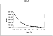
- Figure 4 shows the power frequency losses (W 60 ) and corresponding value of coercive field (H c ) as a function of the peak induction B max .
- the actual losses presented in the Figure are estimated as about 10 % higher due to the overlap section of the sample segments so the power frequency losses (W 60 ) at peak induction of 1.35 tesla is from 0.395 to 0.434 W/kg.
- the coercive force (H c ) after an induction of 1.35 tesla is 9.9 A/m ⁇ 5 %.
- the saturation induction is 1.4 tesla ⁇ 5 %.
- the value at zero induction is estimated from the maximum slopes of 60 Hz B-H loops at low applied fields.
- the maximum relative permeability ( ⁇ rel ) is 57100 ⁇ 10 %.
- a free-standing foil of around 100 ⁇ m thickness is produced in this example.
- the cell is the same as the one used in example 1 and the plating solution is operated at 95°C.
- the plating solution is: FeCl 2 .4H 2 O 1.5 M NaH 2 PO 2 .H 2 O 0.68 M
- the plating is performed under the following conditions: Current densities: 110 A/dm 2 Temperature: 95°C pH: 0.9 Solution velocity: 300 cm/s Anode: Plate of Graphite 10 cm 2 Cathode: Plate of Ti 10 cm 2 Distance between the anode and the cathode: 6 mm
- the resulting free-standing foil has the composition Fe 79.7 P 20.3 .
- the X-ray diffraction analysis of this sample shows a broad spectrum characteristic of an amorphous alloy as shown in Figure 3 .
- the coercive force H c (magnetometer measurement) of the foil is 26.7 A/m after annealing fifteen minutes at 275°C under argon and in a magnetic field produced by permanent magnets that completed a magnetic circuit with the samples.
- the measure of the density for this sample is 7.28 g/cc.
- the coulombic efficiency is near 70 %.
- the thickness of the deposit is as high as 100 ⁇ m. Deposits with thickness higher than 100 ⁇ m can be produced in these conditions by simply increasing the duration of the deposition.
- a transition metal-phosphorus alloy having the desirable properties has been provided in the form of a free-standing foil, as well as the method of production thereof.
Landscapes
- Chemical & Material Sciences (AREA)
- Engineering & Computer Science (AREA)
- Materials Engineering (AREA)
- Metallurgy (AREA)
- Organic Chemistry (AREA)
- Chemical Kinetics & Catalysis (AREA)
- Electrochemistry (AREA)
- Power Engineering (AREA)
- Crystallography & Structural Chemistry (AREA)
- Physics & Mathematics (AREA)
- Electromagnetism (AREA)
- Dispersion Chemistry (AREA)
- Mechanical Engineering (AREA)
- Manufacturing & Machinery (AREA)
- Inorganic Chemistry (AREA)
- Electroplating Methods And Accessories (AREA)
- Soft Magnetic Materials (AREA)
- Electroplating And Plating Baths Therefor (AREA)
Applications Claiming Priority (2)
| Application Number | Priority Date | Filing Date | Title |
|---|---|---|---|
| CA002576752A CA2576752A1 (en) | 2007-02-02 | 2007-02-02 | Amorpheous fe100-a-bpamb foil, method for its preparation and use |
| PCT/CA2008/000205 WO2008092265A1 (en) | 2007-02-02 | 2008-02-01 | AMORPHOUS Fe100-a-bPaMb ALLOY FOIL AND METHOD FOR ITS PREPARATION |
Publications (3)
| Publication Number | Publication Date |
|---|---|
| EP2142678A1 EP2142678A1 (en) | 2010-01-13 |
| EP2142678A4 EP2142678A4 (en) | 2013-04-03 |
| EP2142678B1 true EP2142678B1 (en) | 2019-01-23 |
Family
ID=39671541
Family Applications (1)
| Application Number | Title | Priority Date | Filing Date |
|---|---|---|---|
| EP08706342.6A Not-in-force EP2142678B1 (en) | 2007-02-02 | 2008-02-01 | METHOD FOR MANUFACTURING AN AMORPHOUS Fe100-a-bPaMb ALLOY FOIL |
Country Status (7)
| Country | Link |
|---|---|
| US (1) | US8177926B2 (enExample) |
| EP (1) | EP2142678B1 (enExample) |
| JP (1) | JP5629095B2 (enExample) |
| KR (1) | KR101554217B1 (enExample) |
| CN (1) | CN101600813B (enExample) |
| CA (2) | CA2576752A1 (enExample) |
| WO (1) | WO2008092265A1 (enExample) |
Families Citing this family (25)
| Publication number | Priority date | Publication date | Assignee | Title |
|---|---|---|---|---|
| US8494195B2 (en) | 2007-02-07 | 2013-07-23 | Starkey Laboratories, Inc. | Electrical contacts using conductive silicone in hearing assistance devices |
| US8385573B2 (en) | 2007-09-19 | 2013-02-26 | Starkey Laboratories, Inc. | System for hearing assistance device including receiver in the canal |
| CA2639555A1 (en) | 2008-08-11 | 2008-12-15 | Hyman Ngo | High definition litho applique and emblems |
| US8781141B2 (en) | 2008-08-27 | 2014-07-15 | Starkey Laboratories, Inc. | Modular connection assembly for a hearing assistance device |
| US8798299B1 (en) | 2008-12-31 | 2014-08-05 | Starkey Laboratories, Inc. | Magnetic shielding for communication device applications |
| EP2278828B1 (en) | 2009-07-23 | 2017-09-06 | Starkey Laboratories, Inc. | Method and apparatus for an insulated electromagnetic shield for use in hearing assistance devices |
| DE102009048658A1 (de) | 2009-09-29 | 2011-03-31 | Siemens Aktiengesellschaft | Transformatorkern oder Transformatorblech mit einer amorphen und/oder nanokristallinen Gefügestruktur und Verfahren zu dessen Herstellung |
| US8638965B2 (en) | 2010-07-14 | 2014-01-28 | Starkey Laboratories, Inc. | Receiver-in-canal hearing device cable connections |
| US9049526B2 (en) | 2011-03-19 | 2015-06-02 | Starkey Laboratories, Inc. | Compact programming block connector for hearing assistance devices |
| CN102400191B (zh) * | 2011-11-22 | 2014-04-09 | 沈阳理工大学 | 强磁场下制备Sm-Fe合金磁性薄膜的方法 |
| CN103233253B (zh) * | 2013-05-23 | 2015-04-22 | 浙江工贸职业技术学院 | 一种黑色Mn-Fe-P-B复合镀液、使用方法及其形成的膜层 |
| US9913052B2 (en) | 2013-11-27 | 2018-03-06 | Starkey Laboratories, Inc. | Solderless hearing assistance device assembly and method |
| US9906879B2 (en) | 2013-11-27 | 2018-02-27 | Starkey Laboratories, Inc. | Solderless module connector for a hearing assistance device assembly |
| KR101505873B1 (ko) | 2014-04-15 | 2015-03-25 | (주)테라에너지시스템 | 분리형 전력용 전자기 유도 장치의 제조 방법 |
| KR101666797B1 (ko) | 2014-12-24 | 2016-10-17 | 주식회사 포스코 | Fe-P-Cr 합금 박판 및 그 제조방법 |
| KR101693514B1 (ko) * | 2015-12-24 | 2017-01-06 | 주식회사 포스코 | 전기강판용 Fe-Ni-P 합금 다층 강판 및 이의 제조방법 |
| CN105958859B (zh) * | 2016-03-04 | 2021-09-17 | 上海天轩科技发展有限公司 | 流体动力纳米发电机 |
| CN106756641B (zh) * | 2016-12-14 | 2019-02-26 | 刘志红 | 一种Fe基非晶合金粉末及其制备工艺 |
| CN108231314B (zh) * | 2016-12-14 | 2020-05-26 | 蓬莱市超硬复合材料有限公司 | 一种铁基非晶合金粉末及生产方法 |
| CN108203792B (zh) * | 2016-12-16 | 2020-05-22 | 蓬莱市超硬复合材料有限公司 | 一种铁基非晶粉末及制备方法 |
| US10811801B2 (en) | 2017-11-13 | 2020-10-20 | Te Connectivity Corporation | Electrical connector with low insertion loss conductors |
| CN110998918B (zh) * | 2018-04-10 | 2022-12-06 | 株式会社Lg新能源 | 制备磷化铁的方法、包含磷化铁的锂二次电池用正极和包含所述正极的锂二次电池 |
| JP7164765B2 (ja) * | 2020-07-16 | 2022-11-01 | 東洋鋼鈑株式会社 | 電解鉄箔 |
| EP4183904A4 (en) * | 2020-07-16 | 2024-11-13 | Toyo Kohan Co., Ltd. | ELECTROLYTIC IRON FOIL |
| CN118653110B (zh) * | 2024-08-16 | 2024-11-22 | 慧磁(杭州)科技有限公司 | 一种铁基软磁非晶合金粉末及其制备方法 |
Family Cites Families (25)
| Publication number | Priority date | Publication date | Assignee | Title |
|---|---|---|---|---|
| US1965559A (en) | 1933-08-07 | 1934-07-03 | Cold Metal Process Co | Electrical sheet and method and apparatus for its manufacture and test |
| US3086927A (en) | 1960-08-29 | 1963-04-23 | Horst Corp Of America V D | Iron-phosphorus electroplating |
| US3354059A (en) | 1964-08-12 | 1967-11-21 | Ibm | Electrodeposition of nickel-iron magnetic alloy films |
| US3871836A (en) * | 1972-12-20 | 1975-03-18 | Allied Chem | Cutting blades made of or coated with an amorphous metal |
| JPS5194211A (enExample) | 1975-02-15 | 1976-08-18 | ||
| JPS5833316B2 (ja) * | 1977-02-05 | 1983-07-19 | ソニー株式会社 | 非晶質合金の製造方法 |
| JPS5910998B2 (ja) * | 1976-05-20 | 1984-03-13 | ソニー株式会社 | 非晶質合金の製造方法 |
| CA1072910A (en) * | 1976-05-20 | 1980-03-04 | Satoru Uedaira | Method of manufacturing amorphous alloy |
| US4217135A (en) | 1979-05-04 | 1980-08-12 | General Electric Company | Iron-boron-silicon ternary amorphous alloys |
| JPS57161030A (en) * | 1981-03-28 | 1982-10-04 | Nippon Steel Corp | Improving method for watt loss of thin strip of amorphous magnetic alloy |
| US4533441A (en) * | 1984-03-30 | 1985-08-06 | Burlington Industries, Inc. | Practical amorphous iron electroform and method for achieving same |
| US5032464A (en) | 1986-10-27 | 1991-07-16 | Burlington Industries, Inc. | Electrodeposited amorphous ductile alloys of nickel and phosphorus |
| US4758314A (en) * | 1987-06-29 | 1988-07-19 | General Motors Corporation | Amorphous Fe-Cr-P electroplating bath |
| US5225006A (en) | 1988-05-17 | 1993-07-06 | Kabushiki Kaisha Toshiba | Fe-based soft magnetic alloy |
| JPH02258995A (ja) * | 1988-12-16 | 1990-10-19 | Sumitomo Metal Ind Ltd | 鉄―リン合金磁性薄膜の形成方法及びその磁性薄膜の処理方法 |
| EP0422760A1 (en) | 1989-10-12 | 1991-04-17 | Mitsubishi Rayon Co., Ltd | Amorphous alloy and process for preparation thereof |
| NL9100352A (nl) * | 1991-02-27 | 1992-09-16 | Hoogovens Groep Bv | Werkwijze voor het vervaardigen van ijzerfolie door elektrodepositie. |
| US5518518A (en) * | 1994-10-14 | 1996-05-21 | Fmc Corporation | Amorphous metal alloy and method of producing same |
| AU6653498A (en) * | 1997-02-27 | 1998-09-18 | Fmc Corporation | Amorphous and amorphous/microcrystalline metal alloys and methods for their production |
| RU2170468C1 (ru) * | 2000-04-10 | 2001-07-10 | Мирзоев Рустам Аминович | Электрохимический накопитель энергии высокой удельной мощности и электрод для него |
| US6495019B1 (en) * | 2000-04-19 | 2002-12-17 | Agere Systems Inc. | Device comprising micromagnetic components for power applications and process for forming device |
| DE10229542B4 (de) * | 2002-07-01 | 2004-05-19 | Infineon Technologies Ag | Elektronisches Bauteil mit mehrschichtiger Umverdrahtungsplatte und Verfahren zur Herstellung desselben |
| US7230361B2 (en) | 2003-01-31 | 2007-06-12 | Light Engineering, Inc. | Efficient high-speed electric device using low-loss materials |
| US7494578B2 (en) | 2004-03-01 | 2009-02-24 | Atotech Deutschland Gmbh | Iron-phosphorus electroplating bath and method |
| US7419852B2 (en) * | 2004-08-27 | 2008-09-02 | Micron Technology, Inc. | Low temperature methods of forming back side redistribution layers in association with through wafer interconnects, semiconductor devices including same, and assemblies |
-
2007
- 2007-02-02 CA CA002576752A patent/CA2576752A1/en not_active Abandoned
-
2008
- 2008-02-01 CN CN2008800037901A patent/CN101600813B/zh not_active Expired - Fee Related
- 2008-02-01 JP JP2009547501A patent/JP5629095B2/ja not_active Expired - Fee Related
- 2008-02-01 US US12/525,286 patent/US8177926B2/en not_active Expired - Fee Related
- 2008-02-01 WO PCT/CA2008/000205 patent/WO2008092265A1/en not_active Ceased
- 2008-02-01 EP EP08706342.6A patent/EP2142678B1/en not_active Not-in-force
- 2008-02-01 KR KR1020097018395A patent/KR101554217B1/ko not_active Expired - Fee Related
- 2008-02-01 CA CA2675987A patent/CA2675987C/en not_active Expired - Fee Related
Non-Patent Citations (1)
| Title |
|---|
| None * |
Also Published As
| Publication number | Publication date |
|---|---|
| CN101600813B (zh) | 2012-11-21 |
| JP5629095B2 (ja) | 2014-11-19 |
| KR20090129995A (ko) | 2009-12-17 |
| US8177926B2 (en) | 2012-05-15 |
| EP2142678A1 (en) | 2010-01-13 |
| CA2675987C (en) | 2014-12-09 |
| EP2142678A4 (en) | 2013-04-03 |
| JP2010518252A (ja) | 2010-05-27 |
| CA2576752A1 (en) | 2008-08-02 |
| CN101600813A (zh) | 2009-12-09 |
| KR101554217B1 (ko) | 2015-09-18 |
| CA2675987A1 (en) | 2008-08-07 |
| WO2008092265A1 (en) | 2008-08-07 |
| US20100071811A1 (en) | 2010-03-25 |
Similar Documents
| Publication | Publication Date | Title |
|---|---|---|
| EP2142678B1 (en) | METHOD FOR MANUFACTURING AN AMORPHOUS Fe100-a-bPaMb ALLOY FOIL | |
| JP2010518252A5 (enExample) | ||
| US5435903A (en) | Process for the electrodeposition of an amorphous cobalt-iron-phosphorus alloy | |
| US5484494A (en) | Amorphous alloy and method for its production | |
| Guan et al. | Electrodeposition of low residual stress CoNiMnP hard magnetic thin films for magnetic MEMS actuators | |
| JPH08503522A (ja) | ナノ結晶金属 | |
| JP3229718B2 (ja) | 軟磁性合金、軟磁性薄膜および多層膜 | |
| CN106893954A (zh) | 一种Co基非晶合金粉末及其制备工艺 | |
| Esther et al. | Structural and magnetic properties of electrodeposited Ni-Fe-W thin films | |
| EP0229646A2 (en) | Method for producing a grain-oriented electrical steel sheet having an ultra low watt loss | |
| Xie et al. | Electrodeposition of Sm-Co alloy films with nanocrystalline/amorphous structures from a sulphamate aqueous solution | |
| Yanai et al. | Effects of Glycine in DES-Based Plating Baths on Structural and Magnetic Properties of Fe–Ni Films | |
| Esther et al. | Effect of sodium tungstate on the properties of electrodeposited nanocrystalline Ni-Fe-W films | |
| JP3201763B2 (ja) | 軟磁性薄膜 | |
| TWI422715B (zh) | 鎳鐵合金鍍覆液 | |
| Tiancheng et al. | Influence of electroplating conditions on magnetic properties of Fe-36wt.% Ni alloy film | |
| JP3514800B2 (ja) | 軟磁性薄膜およびその製造方法 | |
| Baskar et al. | Investigation of Annealing Effect on Characteristics of Nickel-Boron Alloy Thin Films | |
| Hussein et al. | Preparation and characterization of cobalt ferrite CoFe2O4 thin films from alcoholic medium and their application restrictions | |
| JPH0729734A (ja) | 磁性薄膜およびその製造方法 | |
| Abdel-Karim et al. | Research Article Electrodeposition and Characterization of Nanocrystalline Ni-Fe Alloys | |
| JPH03126889A (ja) | 非晶質合金の製法 | |
| KR101078924B1 (ko) | 전해증착법을 이용한 코발트계 합금박막 제조방법 | |
| Mikó et al. | Pulse plated amorphous Fe-P thin layers for high frequency magnetic applications | |
| Ding et al. | Ferromagnetic Co/Ni/Fe and Co/Fe multilayer films prepared by a three-filtered-MEVVA-ion-source-deposition system |
Legal Events
| Date | Code | Title | Description |
|---|---|---|---|
| PUAI | Public reference made under article 153(3) epc to a published international application that has entered the european phase |
Free format text: ORIGINAL CODE: 0009012 |
|
| 17P | Request for examination filed |
Effective date: 20090820 |
|
| AK | Designated contracting states |
Kind code of ref document: A1 Designated state(s): AT BE BG CH CY CZ DE DK EE ES FI FR GB GR HR HU IE IS IT LI LT LU LV MC MT NL NO PL PT RO SE SI SK TR |
|
| DAX | Request for extension of the european patent (deleted) | ||
| A4 | Supplementary search report drawn up and despatched |
Effective date: 20130306 |
|
| RIC1 | Information provided on ipc code assigned before grant |
Ipc: C22C 45/02 20060101AFI20130228BHEP Ipc: C25D 1/04 20060101ALI20130228BHEP Ipc: C25D 5/18 20060101ALI20130228BHEP Ipc: C25C 1/24 20060101ALI20130228BHEP Ipc: H01F 41/26 20060101ALI20130228BHEP Ipc: H01F 1/153 20060101ALI20130228BHEP Ipc: C25D 5/48 20060101ALI20130228BHEP Ipc: C25D 3/56 20060101ALI20130228BHEP |
|
| STAA | Information on the status of an ep patent application or granted ep patent |
Free format text: STATUS: EXAMINATION IS IN PROGRESS |
|
| 17Q | First examination report despatched |
Effective date: 20171017 |
|
| GRAP | Despatch of communication of intention to grant a patent |
Free format text: ORIGINAL CODE: EPIDOSNIGR1 |
|
| STAA | Information on the status of an ep patent application or granted ep patent |
Free format text: STATUS: GRANT OF PATENT IS INTENDED |
|
| INTG | Intention to grant announced |
Effective date: 20180410 |
|
| GRAJ | Information related to disapproval of communication of intention to grant by the applicant or resumption of examination proceedings by the epo deleted |
Free format text: ORIGINAL CODE: EPIDOSDIGR1 |
|
| STAA | Information on the status of an ep patent application or granted ep patent |
Free format text: STATUS: EXAMINATION IS IN PROGRESS |
|
| GRAP | Despatch of communication of intention to grant a patent |
Free format text: ORIGINAL CODE: EPIDOSNIGR1 |
|
| STAA | Information on the status of an ep patent application or granted ep patent |
Free format text: STATUS: GRANT OF PATENT IS INTENDED |
|
| INTG | Intention to grant announced |
Effective date: 20180823 |
|
| GRAS | Grant fee paid |
Free format text: ORIGINAL CODE: EPIDOSNIGR3 |
|
| GRAA | (expected) grant |
Free format text: ORIGINAL CODE: 0009210 |
|
| STAA | Information on the status of an ep patent application or granted ep patent |
Free format text: STATUS: THE PATENT HAS BEEN GRANTED |
|
| AK | Designated contracting states |
Kind code of ref document: B1 Designated state(s): AT BE BG CH CY CZ DE DK EE ES FI FR GB GR HR HU IE IS IT LI LT LU LV MC MT NL NO PL PT RO SE SI SK TR |
|
| REG | Reference to a national code |
Ref country code: GB Ref legal event code: FG4D |
|
| REG | Reference to a national code |
Ref country code: CH Ref legal event code: EP |
|
| REG | Reference to a national code |
Ref country code: AT Ref legal event code: REF Ref document number: 1091519 Country of ref document: AT Kind code of ref document: T Effective date: 20190215 |
|
| REG | Reference to a national code |
Ref country code: IE Ref legal event code: FG4D |
|
| REG | Reference to a national code |
Ref country code: DE Ref legal event code: R096 Ref document number: 602008058841 Country of ref document: DE |
|
| PGFP | Annual fee paid to national office [announced via postgrant information from national office to epo] |
Ref country code: GB Payment date: 20190329 Year of fee payment: 12 Ref country code: FR Payment date: 20190320 Year of fee payment: 12 Ref country code: LU Payment date: 20190328 Year of fee payment: 12 Ref country code: DE Payment date: 20190328 Year of fee payment: 12 |
|
| REG | Reference to a national code |
Ref country code: NL Ref legal event code: MP Effective date: 20190123 |
|
| PGFP | Annual fee paid to national office [announced via postgrant information from national office to epo] |
Ref country code: BE Payment date: 20190326 Year of fee payment: 12 |
|
| PG25 | Lapsed in a contracting state [announced via postgrant information from national office to epo] |
Ref country code: NL Free format text: LAPSE BECAUSE OF FAILURE TO SUBMIT A TRANSLATION OF THE DESCRIPTION OR TO PAY THE FEE WITHIN THE PRESCRIBED TIME-LIMIT Effective date: 20190123 |
|
| PG25 | Lapsed in a contracting state [announced via postgrant information from national office to epo] |
Ref country code: PL Free format text: LAPSE BECAUSE OF FAILURE TO SUBMIT A TRANSLATION OF THE DESCRIPTION OR TO PAY THE FEE WITHIN THE PRESCRIBED TIME-LIMIT Effective date: 20190123 Ref country code: SE Free format text: LAPSE BECAUSE OF FAILURE TO SUBMIT A TRANSLATION OF THE DESCRIPTION OR TO PAY THE FEE WITHIN THE PRESCRIBED TIME-LIMIT Effective date: 20190123 Ref country code: LT Free format text: LAPSE BECAUSE OF FAILURE TO SUBMIT A TRANSLATION OF THE DESCRIPTION OR TO PAY THE FEE WITHIN THE PRESCRIBED TIME-LIMIT Effective date: 20190123 Ref country code: ES Free format text: LAPSE BECAUSE OF FAILURE TO SUBMIT A TRANSLATION OF THE DESCRIPTION OR TO PAY THE FEE WITHIN THE PRESCRIBED TIME-LIMIT Effective date: 20190123 Ref country code: PT Free format text: LAPSE BECAUSE OF FAILURE TO SUBMIT A TRANSLATION OF THE DESCRIPTION OR TO PAY THE FEE WITHIN THE PRESCRIBED TIME-LIMIT Effective date: 20190523 Ref country code: NO Free format text: LAPSE BECAUSE OF FAILURE TO SUBMIT A TRANSLATION OF THE DESCRIPTION OR TO PAY THE FEE WITHIN THE PRESCRIBED TIME-LIMIT Effective date: 20190423 Ref country code: FI Free format text: LAPSE BECAUSE OF FAILURE TO SUBMIT A TRANSLATION OF THE DESCRIPTION OR TO PAY THE FEE WITHIN THE PRESCRIBED TIME-LIMIT Effective date: 20190123 |
|
| PGFP | Annual fee paid to national office [announced via postgrant information from national office to epo] |
Ref country code: IT Payment date: 20190329 Year of fee payment: 12 |
|
| REG | Reference to a national code |
Ref country code: AT Ref legal event code: MK05 Ref document number: 1091519 Country of ref document: AT Kind code of ref document: T Effective date: 20190123 |
|
| PG25 | Lapsed in a contracting state [announced via postgrant information from national office to epo] |
Ref country code: IS Free format text: LAPSE BECAUSE OF FAILURE TO SUBMIT A TRANSLATION OF THE DESCRIPTION OR TO PAY THE FEE WITHIN THE PRESCRIBED TIME-LIMIT Effective date: 20190523 Ref country code: BG Free format text: LAPSE BECAUSE OF FAILURE TO SUBMIT A TRANSLATION OF THE DESCRIPTION OR TO PAY THE FEE WITHIN THE PRESCRIBED TIME-LIMIT Effective date: 20190423 Ref country code: HR Free format text: LAPSE BECAUSE OF FAILURE TO SUBMIT A TRANSLATION OF THE DESCRIPTION OR TO PAY THE FEE WITHIN THE PRESCRIBED TIME-LIMIT Effective date: 20190123 Ref country code: GR Free format text: LAPSE BECAUSE OF FAILURE TO SUBMIT A TRANSLATION OF THE DESCRIPTION OR TO PAY THE FEE WITHIN THE PRESCRIBED TIME-LIMIT Effective date: 20190424 Ref country code: LV Free format text: LAPSE BECAUSE OF FAILURE TO SUBMIT A TRANSLATION OF THE DESCRIPTION OR TO PAY THE FEE WITHIN THE PRESCRIBED TIME-LIMIT Effective date: 20190123 |
|
| REG | Reference to a national code |
Ref country code: CH Ref legal event code: PL |
|
| REG | Reference to a national code |
Ref country code: DE Ref legal event code: R097 Ref document number: 602008058841 Country of ref document: DE |
|
| PG25 | Lapsed in a contracting state [announced via postgrant information from national office to epo] |
Ref country code: SK Free format text: LAPSE BECAUSE OF FAILURE TO SUBMIT A TRANSLATION OF THE DESCRIPTION OR TO PAY THE FEE WITHIN THE PRESCRIBED TIME-LIMIT Effective date: 20190123 Ref country code: MC Free format text: LAPSE BECAUSE OF FAILURE TO SUBMIT A TRANSLATION OF THE DESCRIPTION OR TO PAY THE FEE WITHIN THE PRESCRIBED TIME-LIMIT Effective date: 20190123 Ref country code: EE Free format text: LAPSE BECAUSE OF FAILURE TO SUBMIT A TRANSLATION OF THE DESCRIPTION OR TO PAY THE FEE WITHIN THE PRESCRIBED TIME-LIMIT Effective date: 20190123 Ref country code: DK Free format text: LAPSE BECAUSE OF FAILURE TO SUBMIT A TRANSLATION OF THE DESCRIPTION OR TO PAY THE FEE WITHIN THE PRESCRIBED TIME-LIMIT Effective date: 20190123 Ref country code: CZ Free format text: LAPSE BECAUSE OF FAILURE TO SUBMIT A TRANSLATION OF THE DESCRIPTION OR TO PAY THE FEE WITHIN THE PRESCRIBED TIME-LIMIT Effective date: 20190123 Ref country code: RO Free format text: LAPSE BECAUSE OF FAILURE TO SUBMIT A TRANSLATION OF THE DESCRIPTION OR TO PAY THE FEE WITHIN THE PRESCRIBED TIME-LIMIT Effective date: 20190123 |
|
| REG | Reference to a national code |
Ref country code: IE Ref legal event code: MM4A |
|
| PLBE | No opposition filed within time limit |
Free format text: ORIGINAL CODE: 0009261 |
|
| STAA | Information on the status of an ep patent application or granted ep patent |
Free format text: STATUS: NO OPPOSITION FILED WITHIN TIME LIMIT |
|
| PG25 | Lapsed in a contracting state [announced via postgrant information from national office to epo] |
Ref country code: AT Free format text: LAPSE BECAUSE OF FAILURE TO SUBMIT A TRANSLATION OF THE DESCRIPTION OR TO PAY THE FEE WITHIN THE PRESCRIBED TIME-LIMIT Effective date: 20190123 Ref country code: CH Free format text: LAPSE BECAUSE OF NON-PAYMENT OF DUE FEES Effective date: 20190228 Ref country code: LI Free format text: LAPSE BECAUSE OF NON-PAYMENT OF DUE FEES Effective date: 20190228 |
|
| 26N | No opposition filed |
Effective date: 20191024 |
|
| PG25 | Lapsed in a contracting state [announced via postgrant information from national office to epo] |
Ref country code: IE Free format text: LAPSE BECAUSE OF NON-PAYMENT OF DUE FEES Effective date: 20190201 |
|
| PG25 | Lapsed in a contracting state [announced via postgrant information from national office to epo] |
Ref country code: SI Free format text: LAPSE BECAUSE OF FAILURE TO SUBMIT A TRANSLATION OF THE DESCRIPTION OR TO PAY THE FEE WITHIN THE PRESCRIBED TIME-LIMIT Effective date: 20190123 |
|
| PG25 | Lapsed in a contracting state [announced via postgrant information from national office to epo] |
Ref country code: TR Free format text: LAPSE BECAUSE OF FAILURE TO SUBMIT A TRANSLATION OF THE DESCRIPTION OR TO PAY THE FEE WITHIN THE PRESCRIBED TIME-LIMIT Effective date: 20190123 |
|
| PG25 | Lapsed in a contracting state [announced via postgrant information from national office to epo] |
Ref country code: MT Free format text: LAPSE BECAUSE OF NON-PAYMENT OF DUE FEES Effective date: 20190201 |
|
| REG | Reference to a national code |
Ref country code: DE Ref legal event code: R119 Ref document number: 602008058841 Country of ref document: DE |
|
| GBPC | Gb: european patent ceased through non-payment of renewal fee |
Effective date: 20200201 |
|
| REG | Reference to a national code |
Ref country code: BE Ref legal event code: MM Effective date: 20200229 |
|
| PG25 | Lapsed in a contracting state [announced via postgrant information from national office to epo] |
Ref country code: LU Free format text: LAPSE BECAUSE OF NON-PAYMENT OF DUE FEES Effective date: 20200201 |
|
| PG25 | Lapsed in a contracting state [announced via postgrant information from national office to epo] |
Ref country code: FR Free format text: LAPSE BECAUSE OF NON-PAYMENT OF DUE FEES Effective date: 20200229 Ref country code: GB Free format text: LAPSE BECAUSE OF NON-PAYMENT OF DUE FEES Effective date: 20200201 Ref country code: DE Free format text: LAPSE BECAUSE OF NON-PAYMENT OF DUE FEES Effective date: 20200901 |
|
| PG25 | Lapsed in a contracting state [announced via postgrant information from national office to epo] |
Ref country code: BE Free format text: LAPSE BECAUSE OF NON-PAYMENT OF DUE FEES Effective date: 20200229 |
|
| PG25 | Lapsed in a contracting state [announced via postgrant information from national office to epo] |
Ref country code: CY Free format text: LAPSE BECAUSE OF FAILURE TO SUBMIT A TRANSLATION OF THE DESCRIPTION OR TO PAY THE FEE WITHIN THE PRESCRIBED TIME-LIMIT Effective date: 20190123 |
|
| PG25 | Lapsed in a contracting state [announced via postgrant information from national office to epo] |
Ref country code: HU Free format text: LAPSE BECAUSE OF FAILURE TO SUBMIT A TRANSLATION OF THE DESCRIPTION OR TO PAY THE FEE WITHIN THE PRESCRIBED TIME-LIMIT; INVALID AB INITIO Effective date: 20080201 |
|
| PG25 | Lapsed in a contracting state [announced via postgrant information from national office to epo] |
Ref country code: IT Free format text: LAPSE BECAUSE OF NON-PAYMENT OF DUE FEES Effective date: 20200201 |