EP2140977B1 - Vis autotaraudeuse à frapper - Google Patents
Vis autotaraudeuse à frapper Download PDFInfo
- Publication number
- EP2140977B1 EP2140977B1 EP08011817A EP08011817A EP2140977B1 EP 2140977 B1 EP2140977 B1 EP 2140977B1 EP 08011817 A EP08011817 A EP 08011817A EP 08011817 A EP08011817 A EP 08011817A EP 2140977 B1 EP2140977 B1 EP 2140977B1
- Authority
- EP
- European Patent Office
- Prior art keywords
- impact
- control part
- drive shaft
- centrifugal mass
- flywheel
- Prior art date
- Legal status (The legal status is an assumption and is not a legal conclusion. Google has not performed a legal analysis and makes no representation as to the accuracy of the status listed.)
- Not-in-force
Links
Images


Classifications
-
- B—PERFORMING OPERATIONS; TRANSPORTING
- B25—HAND TOOLS; PORTABLE POWER-DRIVEN TOOLS; MANIPULATORS
- B25B—TOOLS OR BENCH DEVICES NOT OTHERWISE PROVIDED FOR, FOR FASTENING, CONNECTING, DISENGAGING OR HOLDING
- B25B21/00—Portable power-driven screw or nut setting or loosening tools; Attachments for drilling apparatus serving the same purpose
- B25B21/02—Portable power-driven screw or nut setting or loosening tools; Attachments for drilling apparatus serving the same purpose with means for imparting impact to screwdriver blade or nut socket
- B25B21/026—Impact clutches
Definitions
- the invention relates to an impact wrench with a rotary impact mechanism for screwing and drilling wherein such impact wrench are used inter alia to produce or solve high-strength threaded connections.
- Impact wrenches have been known in the art for many years, the function of the rotary impact mechanism being based on the idea of temporarily storing the drive energy of an engine and periodically applying it to an output shaft within a very short working phase. These periodically emitted angular momentum produce a significantly higher resulting depending on the pulse duration Drive torque as possible with a constant torque curve. From the drive side, the system receives kinetic energy in the form of torque and speed, which is cached in an assembly, for example in a spring or a rotating mass. The storage process takes each time until a control mechanism ensures that the stored energy is delivered via a hammer on an anvil.
- both the anvil and the hammer of the striking mechanism on impact jaws wherein the hammer comprises a flywheel, which is formed by the massive part of the hammer, which is accelerated by this mass, the kinetic energy is transferred to the anvil.
- the anvil is in a rotationally fixed connection to the output, so also for screwing.
- the control mechanism provides for the time-limited delivery of energy to the anvil, so that the compound dissolves again when the stored energy is released.
- phase 1 the energy is collected and stored and in phase 2 the stored energy is released again.
- the energy stored in phase 1 is determined by the input quantities of torque, speed and stroke rate. The higher the stroke rate, the shorter Phase 1 is in terms of time and the less energy can be stored, because the engine can only apply a given torque and thus the duration of the storage process is crucial.
- the second phase also decides the duration of the energy tax. If the stored energy is delivered to the output in a shorter time, ie the duration of the stroke is shorter, the resulting torque peak will be higher than with a longer duration of the stroke.
- the typical torque curve of an impact wrench is created by temporarily storing energy over a longer period of time, which is delivered abruptly to the output in a very short period of time.
- Such an impact wrench is for example in the DE 43 01 610 A1 described above.
- the hammer seat in this case has the actual flywheel, wherein the hammer block is guided axially movable in the hammer seat.
- recesses may be provided in the hammer seat in which the Baking jaws of the hammer block are axially movable.
- the impact jaws of the hammer block protrude radially from the hammer block to the outside and are received in the grooves.
- the impact jaws of the hammer block over the hammer seat in the axial direction protrude and interact with the impact jaws of the anvil.
- a disadvantage of this design is the risk of tilting the impact jaws of the anvil or the hammer block in relation to the hammer seat and the drive shaft.
- the invention is achieved by an impact wrench with the features of claim 1.
- An impact wrench works as follows: It can be provided that in a first non-impact case, the control part rotates with the anvil and the drive shaft, wherein the impact jaws of the anvil and control part abut each other and are engaged, that is to cover in the axial direction, being this operation takes place until the maximum torque of the screwdriver is reached without hitting. This usually means until it comes to a first blockage of the screw.
- control part usually performs in case of impact in addition to the relative axial movement to the drive shaft relative rotational movement to the drive shaft.
- the axial and the rotational movement are oscillating.
- the flywheel has a substantially hollow cylindrical shape
- the axial ends may also have an extension in the radial direction, which may be greater than the thickness of the shell, that is, the end faces may form a corner to the interior of the coat.
- control part does not act beyond the flywheel in the axial direction in each case of operation, both during energy storage and energy discharge for the impact.
- control part in the radial direction either with the circumference of Completing flywheel, that is in particular guided in grooves in the flywheel, which break the outer circumference of the flywheel, so that the outer contour, eg the impact jaws or separate ribs of the control part, complements the outer contour of the flywheel and in particular continues steadily or alternatively
- the control part is designed so that it is completely guided in the flywheel and taken in this in the radial direction.
- the grooves of the flywheel then do not extend to the outer contour of the same.
- ribs may be provided on the flywheel instead of the grooves which engage in grooves of the control part.
- a particularly good guidance in the axial direction in the release of the stored energy to the control part can be achieved and thus tilting of the control part can be prevented even safer.
- the impact mechanism is designed as a V-groove impact mechanism, wherein the control part performs an axially oscillatory rotational movement with respect to the drive shaft in the case of impact.
- the control part performs both an axial and a rotational relative movement in the case of impact.
- the control part moves alternately axially on the drive shaft in the direction of the drive-side end of the drive shaft and the output-side end of the drive shaft in a groove back and forth.
- the groove is V-shaped and the tip of the V points in the direction of the output side of the shaft, wherein caused by the axial movement due to the V-shape of the grooves at the same time also a relative rotational movement of the control part to the drive shaft.
- the Control part can in this case via a ball guide in the V-grooves, preferably two V-grooves are arranged diametrically opposite to the drive shaft, be performed.
- corresponding running surfaces for the ball can be mounted in the control part.
- a V-groove impact works as follows: Before an impact case occurs, the anvil rotates about its impact jaws which bear against the impact jaws of the control part, together with the control part and the drive shaft without a relative movement between the individual components.
- the control part also drives the flywheel.
- This larger torque between the anvil and control part to a decoupling of the impact jaws. Due to the further rotation of the drive shaft, which is transmitted to the control part and the counter-support of the anvil, there is a wandering of the control part on the drive shaft in the V-grooves.
- the control part Due to the provision of the V-grooves, the control part is at the same time moved away from the anvil with the rotation relative to the drive shaft in the axial direction and there is a catching in the axial direction of the impact jaws of the control part and the anvil.
- the control part can move freely in the rotational direction again and is accelerated by the stored energy, which is stored in a spring by the axial movement of the control part in the drive direction until it is at the end of its rotational movement and axial movement against striking the impact jaws of the anvil with its impact jaws and so performs a blow in the circumferential direction, which leads to a further tightening or loosening of the machined bfalls.
- flywheel grooves or ribs are provided which can extend to the outer periphery of the flywheel or are mounted only inside the flywheel, without extending to the peripheral or outer surface of the flywheel.
- grooves or ribs are now on corresponding corresponding ribs or grooves, which can be formed for example by separate ribs or grooves, but also by the impact jaws of the control part, the control part in the axial direction and at the same time takes place via this coupling the rotation transmission from Control part on the flywheel.
- a spring is arranged between the flywheel and control part, which serves to store and release the impact energy, wherein the spring is supported against the flywheel and the control part.
- a thrust bearing in particular in the form of a ball bearing, may be provided to allow the relative movement in rotational terms between flywheel and drive shaft and to store the flywheel on the drive shaft.
- control part is completely absorbed in the flywheel, that is, both in the axial and in the radial direction, it is particularly advantageous if the impact jaws of the control part and the anvil, which also completely or partially immerse in the flywheel to to cooperate with the impact jaws of the control part, only a slight play in the radial direction to the wall of the flywheel.
- the impact jaws of the control part In this way, the space can be exploited particularly well and the impact jaws are made as large as possible and at the same time a leadership of the impact jaws against tilting can be achieved.
- the division of the hammer in a separate control part and in a separate flywheel therefore offers the opportunity to provide a larger flywheel while lower axial space necessary for the movement to generate the impact the advantage that lower vibrations in the axial direction arise because the flywheel performs no axial movement and only the control part, which has a much lower mass, is moved in the axial direction. Since the mass of the control part is significantly lower compared to the flywheel mass, the vibration excitation in the direction of the axis of rotation is reduced considerably.
- the impact jaws of the control part within the flywheel, that is, without these project beyond the flywheel in the axial direction, that the impact jaws are arranged closer to the center of gravity of the flywheel and beyond tilting by the guide in the flywheel, especially if the flywheel receives the control part in the radial direction, be prevented safer.
- the impact wrench is a cordless wrench, with cordless tools generally having the advantage at any location and also in difficult to use in difficult applications.
- the impact function is particularly advantageous in cordless tools, since in devices with direct electrical connection, the torque design can be made so that higher torques are achieved, so that if necessary, can be used without an additional impact function.
- FIG. 1 shows a striking mechanism according to the invention with a drive shaft 10 comprising a drive-side end 12 with which it (not shown) with a drive motor may be coupled in particular via a transmission.
- V-shaped grooves 14 are provided, wherein the tip of the V-shaped grooves to the output side end 16 of the drive shaft 10 indicates.
- V-shaped grooves 14 wherein two grooves 14 are arranged diametrically opposite each other in the drive shaft 10, a ball 18 is guided in each case, wherein in a control part 20 corresponding running surfaces (not shown) for receiving the ball 18th are provided.
- the control member 20 can move in the region of the grooves 14 relative to the drive shaft 10 and in particular perform both an axial and rotary oscillating motion.
- the percussion includes a flywheel 22, wherein the flywheel 22 together with the control part 20 forms the so-called hammer of the striking mechanism.
- the control part 20 also includes impact jaws 24 which protrude in the axial direction 26 on the actual control part in the output side direction and with in FIG. 1 not shown impact jaws of an anvil cooperate.
- the control part 20 is guided in the flywheel 22 in the axial direction movable, but rotatably coupled to the flywheel 22.
- the flywheel 22 includes grooves 28 in which the impact jaws 24 engage and in which they are movable in the axial direction and over which the rotation transmission takes place.
- the grooves 28 are arranged completely within the flywheel 22, so that the control part 20 protrudes in the radial direction in no operating state on the flywheel 22, but is completely absorbed in this.
- a spring 30 is provided, which is arranged between the control part 20 and drive shaft 10 and which is compressed during the movement of the control member 20 along the V-grooves 14 to an energy storage, wherein the energy then Separating the whipping jaws 24 from the anvil striking jaws again discharges.
- a thrust bearing 32 is provided that is provided between the drive shaft 10 and the flywheel 22.
- flywheel 22 performs no axial movement and thus causes no vibration in this direction and the flywheel 22 of the relative rotation to the drive shaft 10, which performs the control part 20, can follow.
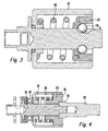
- FIG. 2 now shows a design of the impact mechanism in assembled form, wherein between the drive shaft 10 and flywheel 22, wherein the flywheel 22 is not shown here, the thrust bearing 32 is arranged. Shown here is the engagement of the impact jaws 24 with the impact jaws 34 of the anvil 36, which is coupled to an output shaft 38 which is connected to a tool holder.
- the impact jaws 34 of the anvil 36 are here designed so that they are completely absorbed in the flywheel 22 and are enclosed in the radial direction by the flywheel 22.
- the flywheel 22 is also taken along, but does not perform any axial movement, so that the impact energy can be provided by the larger compared to the control part 20 flywheel 22.
- FIG. 3 shows now a design again without anvil, but with mounted flywheel 22, which can be seen that the control part 20 is completely enclosed in the axial and in the radial direction by the flywheel 22, the flywheel 22 here is a running or guiding surface for the balls 18, which are guided in the V-grooves 14 has. Not shown in the present sectional plane, the axial guidance on the impact jaws 24 in the grooves of the flywheel 22nd
- FIG. 4 shows a fully assembled striking mechanism comprising an output shaft 38 with the anvil 36, wherein in the present section, the striking jaws 34 can not be seen, but rather the impact jaws 24 of the control part 20 are shown cut, which are guided in grooves 28 of the flywheel 22 and with cooperate in the flywheel 22 also plunging jaws 34 of the anvil 36, for the transmission of rotational energy.
- the thrust bearing 32 is provided to ensure a purely rotational relative movement of the flywheel 22.
- the arrangement of the impact jaws 24 in the flywheel 22 and thus the engagement of the impact jaws 34 in the Flywheel 22 are the impact jaws 24 full length within the grooves 28 of the flywheel 22. This increases the area over which the pulse is transmitted from the flywheel 22 to the control part 20.
- the transfer surfaces are in this way closer to the center of gravity of the flywheel 22nd
- the transfer surfaces between the impact jaws of the control part 20 and the anvil 36 are designed so that they lie flat against each other.
- they can also, as in FIG. 1 and 2 shown to be formed so that only a line contact takes place.
- the impact jaws 34 of the anvil 36 must be shortened in terms of their length in the radial direction, since they now come to rest within the flywheel 22, they can be widened accordingly to provide the necessary rigidity.
Landscapes
- Engineering & Computer Science (AREA)
- Mechanical Engineering (AREA)
- Percussive Tools And Related Accessories (AREA)
- Heat Treatment Of Articles (AREA)
Claims (12)
- Visseuse à chocs comprenant un moteur d'entraînement pour l'entraînement d'un arbre d'entrée (10) et d'un arbre de sortie (38) pouvant être couplé à un logement d'outil, ainsi qu'un mécanisme de choc, dans laquelle le mécanisme de choc comprend une enclume (36) qui comporte des premières mâchoires de choc (34) couplées à l'arbre de sortie (38), ainsi qu'un marteau qui est guidé sur l'arbre d'entrée (10), dans laquelle le marteau comporte des secondes mâchoires de choc (24) qui sont en prise avec les premières mâchoires de choc (34) pour la transmission de la rotation, le marteau comprenant une masse d'inertie (22) et une partie de commande (20), dans laquelle la partie de commande (20) porte les secondes mâchoires de choc (24) tournant avec l'arbre d'entrée (10) dans le cas sans choc et décrivant une oscillation axiale et une oscillation rotative par rapport à l'arbre d'entrée (10) dans le cas de choc, dans laquelle la partie de commande (20) transmet la rotation de l'arbre d'entrée (10) à la masse d'inertie (22) et est guidée mobile dans la direction axiale pour l'exécution de la fonction de choc, et dans laquelle la masse d'inertie (22) ne décrit aucun mouvement axial, caractérisée en ce que les mâchoires de choc (24) de la partie de commande (20) ne débordent pas au-delà de la masse d'inertie (22) dans la direction axiale.
- Visseuse à chocs selon la revendication 1, caractérisée en ce que les mâchoires de choc (34) de l'enclume (36) sont engagées entièrement ou partiellement dans la masse d'inertie (22) dans la direction axiale.
- Visseuse à chocs selon l'une des revendications précédentes, caractérisée en ce que la masse d'inertie (22) est reliée solidairement en rotation à la partie de commande (20).
- Visseuse à chocs selon l'une des revendications précédentes, caractérisée en ce que la masse d'inertie (22) présente une forme cylindrique creuse.
- Visseuse à chocs selon l'une des revendications précédentes, caractérisée en ce qu'un ressort servant à accumule et à libérer l'énergie de choc est guidé dans la masse d'inertie (22), et en ce que le ressort prend appui contre la masse d'inertie (22) et contre la partie de commande (20).
- Visseuse à chocs selon l'une des revendications précédentes, caractérisée en ce que le mécanisme de choc est constitué par un mécanisme de choc à rainures en V dont les rainures en V (14) sont formées dans l'arbre d'entrée (10) et dans la partie de commande, et au moyen desquelles la partie de commande (20) est déplacée sur l'arbre d'entrée (10) par l'action de billes (18) qui sont guidées dans les rainures (14).
- Visseuse à chocs selon l'une des revendications précédentes, caractérisée en ce que la masse d'inertie (22) comporte des rainures dans lesquelles s'engagent des nervures qui sont formées en particulier par les mâchoires de chocs (24) de la partie de commande (20).
- Visseuse à chocs selon la revendication 7, caractérisée en ce que les nervures de la partie de commande (20) complètent par leurs surfaces périphériques la surface périphérique de la masse d'inertie (22).
- Visseuse à chocs selon l'une des revendications précédentes, caractérisée en ce que la partie de commande (20) est contenue dans la masse d'inertie (22) dans la direction radiale et entourée par cette dernière.
- Tisseuse à chocs selon l'une des revendications précédentes, caractérisée en ce qu'un palier axial (32) est prévu entre la masse d'invertie (22) et l'arbre d'entrée (10).
- Visseuse à chocs selon l'une des revendication précédentes, caractérisée en ce que les mâchoires de choc (34) de l'enclume (36) et/ou de la partie de commande (20) présentent seulement un petit jeu par rapport à la paroi de la masse d'inertie (22) dans la direction radiale,
- Visseuse à chocs selon l'une des revendications précédentes, caractérisée en ce que la visseuse à chocs est un appareil à batterie.
Priority Applications (4)
| Application Number | Priority Date | Filing Date | Title |
|---|---|---|---|
| AT08011817T ATE554883T1 (de) | 2008-07-01 | 2008-07-01 | Schlagschrauber |
| EP08011817A EP2140977B1 (fr) | 2008-07-01 | 2008-07-01 | Vis autotaraudeuse à frapper |
| US12/485,217 US20100000749A1 (en) | 2008-07-01 | 2009-06-16 | Impact Wrench |
| CN200910151843.0A CN101618535B (zh) | 2008-07-01 | 2009-07-01 | 冲击扳手 |
Applications Claiming Priority (1)
| Application Number | Priority Date | Filing Date | Title |
|---|---|---|---|
| EP08011817A EP2140977B1 (fr) | 2008-07-01 | 2008-07-01 | Vis autotaraudeuse à frapper |
Publications (2)
| Publication Number | Publication Date |
|---|---|
| EP2140977A1 EP2140977A1 (fr) | 2010-01-06 |
| EP2140977B1 true EP2140977B1 (fr) | 2012-04-25 |
Family
ID=39941594
Family Applications (1)
| Application Number | Title | Priority Date | Filing Date |
|---|---|---|---|
| EP08011817A Not-in-force EP2140977B1 (fr) | 2008-07-01 | 2008-07-01 | Vis autotaraudeuse à frapper |
Country Status (4)
| Country | Link |
|---|---|
| US (1) | US20100000749A1 (fr) |
| EP (1) | EP2140977B1 (fr) |
| CN (1) | CN101618535B (fr) |
| AT (1) | ATE554883T1 (fr) |
Families Citing this family (45)
| Publication number | Priority date | Publication date | Assignee | Title |
|---|---|---|---|---|
| EP1961522B1 (fr) * | 2007-02-23 | 2015-04-08 | Robert Bosch Gmbh | Outil d'alimentation rotatif qui fonctionne en mode d'impact ou en mode de forage |
| EP2285516B1 (fr) * | 2008-04-22 | 2017-03-15 | Gérard Grand | Mécanisme d'impact |
| DE102010030098A1 (de) * | 2010-06-15 | 2011-12-15 | Hilti Aktiengesellschaft | Eintreibvorrichtung |
| JP2012006101A (ja) * | 2010-06-23 | 2012-01-12 | Makita Corp | 打撃工具 |
| TWM393379U (en) * | 2010-07-23 | 2010-12-01 | Top Gearbox Industry Co Ltd | Switching device for output configuration |
| DE102010038210A1 (de) | 2010-10-15 | 2012-04-19 | Wera-Werk Hermann Werner Gmbh & Co. Kg | Drehmomentübertragungsvorrichtung zur Verwendung mit einem Drehschlagschrauber |
| EP2635410B1 (fr) | 2010-11-04 | 2016-10-12 | Milwaukee Electric Tool Corporation | Outil à chocs avec embrayage réglable |
| DE102011007691A1 (de) * | 2010-11-29 | 2012-05-31 | Robert Bosch Gmbh | Hammerschlagwerk |
| DE102011000710A1 (de) | 2011-02-14 | 2012-08-16 | Wera-Werk Hermann Werner Gmbh & Co. Kg | Drehmomentübertragungseinrichtung in Form eines Bitfutters |
| CN103402707B (zh) * | 2011-03-11 | 2016-06-22 | S·D·温纳德 | 手持式驱动装置 |
| US9566692B2 (en) * | 2011-04-05 | 2017-02-14 | Ingersoll-Rand Company | Rotary impact device |
| US9463557B2 (en) | 2014-01-31 | 2016-10-11 | Ingersoll-Rand Company | Power socket for an impact tool |
| US9469017B2 (en) | 2014-01-31 | 2016-10-18 | Ingersoll-Rand Company | One-piece power socket for an impact tool |
| JP5468570B2 (ja) * | 2011-06-17 | 2014-04-09 | 株式会社マキタ | 打撃工具 |
| SE535919C2 (sv) * | 2011-06-30 | 2013-02-19 | Atlas Copco Ind Tech Ab | Elektriskt motordrivet verktyg |
| EP2556922B1 (fr) * | 2011-08-09 | 2014-03-19 | C. & E. Fein GmbH | Outil manuel à moteur |
| DE102011089910A1 (de) * | 2011-12-27 | 2013-06-27 | Robert Bosch Gmbh | Handwerkzeugvorrichtung |
| DE102012209446A1 (de) * | 2012-06-05 | 2013-12-05 | Robert Bosch Gmbh | Handwerkzeugmaschinenvorrichtung |
| CN103669137A (zh) * | 2012-09-19 | 2014-03-26 | 蓬莱奥斯勃机械有限公司 | 手动冲击式轨枕螺栓扳手 |
| US9227313B2 (en) * | 2012-11-27 | 2016-01-05 | Power Network Industry Co., Ltd. | Operation mode switching mechanism |
| JP6032041B2 (ja) * | 2013-02-13 | 2016-11-24 | 日立工機株式会社 | インパクト工具 |
| WO2015013026A2 (fr) * | 2013-07-24 | 2015-01-29 | Promega Corporation | Procédés de distribution et d'utilisation d'un contenant rfid mobile |
| US9539715B2 (en) * | 2014-01-16 | 2017-01-10 | Ingersoll-Rand Company | Controlled pivot impact tools |
| US9908208B2 (en) * | 2014-01-28 | 2018-03-06 | Tiger Tool International Incorporated | Offset press for removing wheel studs |
| US9751199B2 (en) | 2014-02-10 | 2017-09-05 | Tiger Tool International Incorporated | Disk brake wheel stud insertion and removal tool |
| DE102014209398A1 (de) * | 2014-05-19 | 2015-11-19 | Robert Bosch Gmbh | Schlagkörper für ein mechanisches Drehschlagwerk |
| WO2016017545A1 (fr) * | 2014-07-31 | 2016-02-04 | 日立工機株式会社 | Outil à percussion |
| GB201421576D0 (en) | 2014-12-04 | 2015-01-21 | Black & Decker Inc | Drill |
| GB201421577D0 (en) | 2014-12-04 | 2015-01-21 | Black & Decker Inc | Drill |
| DE102015201573A1 (de) * | 2015-01-29 | 2016-08-04 | Robert Bosch Gmbh | Schlagwerkvorrichtung, insbesondere für einen Schlagschrauber |
| US10603770B2 (en) * | 2015-05-04 | 2020-03-31 | Milwaukee Electric Tool Corporation | Adaptive impact blow detection |
| US20160332286A1 (en) * | 2015-05-13 | 2016-11-17 | Wen Hung Chiang | Tool holder device |
| US11065743B2 (en) | 2015-05-13 | 2021-07-20 | Wen Hung Chiang | Tool holder device |
| US10471573B2 (en) * | 2016-01-05 | 2019-11-12 | Milwaukee Electric Tool Corporation | Impact tool |
| US20170197305A1 (en) * | 2016-01-10 | 2017-07-13 | Omnitek Partners Llc | Chisel Head Attachment For Electric Drills and Screw Drivers and the Like and Electric Chisels |
| TWI603815B (zh) * | 2016-04-13 | 2017-11-01 | 優鋼機械股份有限公司 | 旋轉式緊固裝置 |
| US11285588B2 (en) * | 2017-12-11 | 2022-03-29 | Atlas Copco Industrial Technique Ab | Electric pulse tool |
| AU2019101751A4 (en) * | 2018-02-19 | 2020-11-05 | Milwaukee Electric Tool Corporation | Impact tool |
| US11135711B2 (en) | 2018-03-16 | 2021-10-05 | Tiger Tool International Incorporated | Retaining ring plier systems and methods |
| JP6979605B2 (ja) * | 2018-05-11 | 2021-12-15 | パナソニックIpマネジメント株式会社 | インパクト回転工具 |
| CN215789519U (zh) * | 2018-12-21 | 2022-02-11 | 米沃奇电动工具公司 | 冲击工具 |
| US11623336B2 (en) * | 2019-08-22 | 2023-04-11 | Ingersoll-Rand Industrial U.S., Inc. | Impact tool with vibration isolation |
| CN211805940U (zh) * | 2019-09-20 | 2020-10-30 | 米沃奇电动工具公司 | 冲击工具和锤头 |
| US11815132B2 (en) | 2020-03-13 | 2023-11-14 | Tiger Tool International Incorporated | Bushing insertion systems and methods |
| CN112757206A (zh) * | 2021-01-06 | 2021-05-07 | 四川九洲电器集团有限责任公司 | 一种抗冲击的自动拧紧扳手及其自拧紧方法 |
Family Cites Families (13)
| Publication number | Priority date | Publication date | Assignee | Title |
|---|---|---|---|---|
| US4811797A (en) * | 1987-10-21 | 1989-03-14 | Nauchno-Proizvodstvennoe Obiedinenie Po Mekhanizirovannomu Stroitelnomu Instrumentru I Otdelochnym Mashinam | Impact wrench |
| DE4301610C2 (de) | 1993-01-22 | 1996-08-14 | Bosch Gmbh Robert | Schlagschrauber |
| US6158526A (en) * | 1999-03-09 | 2000-12-12 | Snap-On Tools Company | Reversible impact mechanism with structure limiting hammer travel |
| JP4405900B2 (ja) * | 2004-03-10 | 2010-01-27 | 株式会社マキタ | インパクトドライバ |
| US7308948B2 (en) * | 2004-10-28 | 2007-12-18 | Makita Corporation | Electric power tool |
| JP4468786B2 (ja) * | 2004-10-28 | 2010-05-26 | 株式会社マキタ | インパクト工具 |
| US20060237205A1 (en) * | 2005-04-21 | 2006-10-26 | Eastway Fair Company Limited | Mode selector mechanism for an impact driver |
| JP4597849B2 (ja) * | 2005-12-01 | 2010-12-15 | 株式会社マキタ | 回転打撃工具 |
| US7168503B1 (en) * | 2006-01-03 | 2007-01-30 | Mobiletron Electronics Co., Ltd. | Power hand tool |
| DE202006014850U1 (de) * | 2006-09-27 | 2006-11-23 | Robert Bosch Gmbh | Mechanisches Schlagwerk |
| US7494437B2 (en) * | 2007-01-04 | 2009-02-24 | Ting Kuang Chen | Impact power tool |
| DE202007011843U1 (de) | 2007-08-24 | 2008-01-03 | Jenn Feng Industrial Co., Ltd., Ping Chang City | Schlagmechanismus für ein Motorwerkzeug mit hohem Drehmoment |
| US7588093B2 (en) * | 2007-09-05 | 2009-09-15 | Grand Gerard M | Impact mechanism |
-
2008
- 2008-07-01 AT AT08011817T patent/ATE554883T1/de active
- 2008-07-01 EP EP08011817A patent/EP2140977B1/fr not_active Not-in-force
-
2009
- 2009-06-16 US US12/485,217 patent/US20100000749A1/en not_active Abandoned
- 2009-07-01 CN CN200910151843.0A patent/CN101618535B/zh not_active Expired - Fee Related
Also Published As
| Publication number | Publication date |
|---|---|
| US20100000749A1 (en) | 2010-01-07 |
| EP2140977A1 (fr) | 2010-01-06 |
| ATE554883T1 (de) | 2012-05-15 |
| CN101618535B (zh) | 2013-07-03 |
| CN101618535A (zh) | 2010-01-06 |
Similar Documents
| Publication | Publication Date | Title |
|---|---|---|
| EP2140977B1 (fr) | Vis autotaraudeuse à frapper | |
| EP2140976B1 (fr) | Vis autotaraudeuse à frapper | |
| DE19505068C2 (de) | Schlagwerkzeug | |
| EP2265420B1 (fr) | Machine-outil portative pour outils entraînés en frappe | |
| DE3932660C2 (de) | Schlagbohrmaschine mit mechanischer Schlagübertragung | |
| EP2517835B1 (fr) | Outil à moteur | |
| EP2140978B1 (fr) | Vis autotaraudeuse à frapper | |
| EP3638457B1 (fr) | Machine-outil portative | |
| EP2457694A2 (fr) | Outil électrique | |
| WO2002020224A1 (fr) | Porte-outil pour une machine-outil | |
| EP2612732A1 (fr) | Dispositif d'outil manuel | |
| EP2612731B1 (fr) | Dispositif d'outil manuel | |
| DE102010038210A1 (de) | Drehmomentübertragungsvorrichtung zur Verwendung mit einem Drehschlagschrauber | |
| DE102016115812A1 (de) | Schlagwerkzeug | |
| EP2331298B1 (fr) | Outil à accouplement de rattrapage | |
| EP2191939B1 (fr) | Dispositif pour machine-outil portable | |
| WO2009083307A1 (fr) | Machine-outil dotée d'un dispositif de transmission comportant au moins un arbre intermédiaire logé de façon rotative | |
| EP2132005B1 (fr) | Mécanisme rotopercutant | |
| EP1677950B1 (fr) | Outil de percussion pour une machine-outil a main | |
| EP1618999B1 (fr) | marteau perforateur et/ou marteau-burineur | |
| WO2009092366A2 (fr) | Mécanisme de percussion pour une machine-outil, notamment pour une machine-outil manuelle telle qu'un marteau perforateur électrique ou une visseuse à percussion | |
| EP3829819A1 (fr) | Machine-outil portative, en particulier clé à choc | |
| DE1299579B (de) | Transportables, motorisch angetriebenes Drehschlaggeraet | |
| DE3500397A1 (de) | Elektrische schlagbohrmaschine | |
| WO2018224214A1 (fr) | Dispositif de serrage et perceuse à ultrasons |
Legal Events
| Date | Code | Title | Description |
|---|---|---|---|
| PUAI | Public reference made under article 153(3) epc to a published international application that has entered the european phase |
Free format text: ORIGINAL CODE: 0009012 |
|
| AK | Designated contracting states |
Kind code of ref document: A1 Designated state(s): AT BE BG CH CY CZ DE DK EE ES FI FR GB GR HR HU IE IS IT LI LT LU LV MC MT NL NO PL PT RO SE SI SK TR |
|
| AX | Request for extension of the european patent |
Extension state: AL BA MK RS |
|
| 17P | Request for examination filed |
Effective date: 20100127 |
|
| AKX | Designation fees paid |
Designated state(s): AT BE CH DE FR GB LI |
|
| GRAP | Despatch of communication of intention to grant a patent |
Free format text: ORIGINAL CODE: EPIDOSNIGR1 |
|
| GRAS | Grant fee paid |
Free format text: ORIGINAL CODE: EPIDOSNIGR3 |
|
| GRAA | (expected) grant |
Free format text: ORIGINAL CODE: 0009210 |
|
| AK | Designated contracting states |
Kind code of ref document: B1 Designated state(s): AT BE CH DE FR GB LI |
|
| REG | Reference to a national code |
Ref country code: GB Ref legal event code: FG4D Free format text: NOT ENGLISH |
|
| REG | Reference to a national code |
Ref country code: CH Ref legal event code: EP |
|
| REG | Reference to a national code |
Ref country code: AT Ref legal event code: REF Ref document number: 554883 Country of ref document: AT Kind code of ref document: T Effective date: 20120515 |
|
| REG | Reference to a national code |
Ref country code: DE Ref legal event code: R096 Ref document number: 502008007036 Country of ref document: DE Effective date: 20120614 |
|
| BERE | Be: lapsed |
Owner name: METABOWERKE G.M.B.H. Effective date: 20120731 |
|
| REG | Reference to a national code |
Ref country code: CH Ref legal event code: PL |
|
| PLBE | No opposition filed within time limit |
Free format text: ORIGINAL CODE: 0009261 |
|
| STAA | Information on the status of an ep patent application or granted ep patent |
Free format text: STATUS: NO OPPOSITION FILED WITHIN TIME LIMIT |
|
| 26N | No opposition filed |
Effective date: 20130128 |
|
| PG25 | Lapsed in a contracting state [announced via postgrant information from national office to epo] |
Ref country code: LI Free format text: LAPSE BECAUSE OF NON-PAYMENT OF DUE FEES Effective date: 20120731 Ref country code: CH Free format text: LAPSE BECAUSE OF NON-PAYMENT OF DUE FEES Effective date: 20120731 |
|
| REG | Reference to a national code |
Ref country code: DE Ref legal event code: R097 Ref document number: 502008007036 Country of ref document: DE Effective date: 20130128 |
|
| PG25 | Lapsed in a contracting state [announced via postgrant information from national office to epo] |
Ref country code: BE Free format text: LAPSE BECAUSE OF NON-PAYMENT OF DUE FEES Effective date: 20120731 |
|
| REG | Reference to a national code |
Ref country code: AT Ref legal event code: MM01 Ref document number: 554883 Country of ref document: AT Kind code of ref document: T Effective date: 20130701 |
|
| PGFP | Annual fee paid to national office [announced via postgrant information from national office to epo] |
Ref country code: DE Payment date: 20140724 Year of fee payment: 7 |
|
| PG25 | Lapsed in a contracting state [announced via postgrant information from national office to epo] |
Ref country code: AT Free format text: LAPSE BECAUSE OF NON-PAYMENT OF DUE FEES Effective date: 20130701 |
|
| PGFP | Annual fee paid to national office [announced via postgrant information from national office to epo] |
Ref country code: GB Payment date: 20140721 Year of fee payment: 7 Ref country code: FR Payment date: 20140724 Year of fee payment: 7 |
|
| REG | Reference to a national code |
Ref country code: DE Ref legal event code: R119 Ref document number: 502008007036 Country of ref document: DE |
|
| GBPC | Gb: european patent ceased through non-payment of renewal fee |
Effective date: 20150701 |
|
| PG25 | Lapsed in a contracting state [announced via postgrant information from national office to epo] |
Ref country code: DE Free format text: LAPSE BECAUSE OF NON-PAYMENT OF DUE FEES Effective date: 20160202 Ref country code: GB Free format text: LAPSE BECAUSE OF NON-PAYMENT OF DUE FEES Effective date: 20150701 |
|
| REG | Reference to a national code |
Ref country code: FR Ref legal event code: ST Effective date: 20160331 |
|
| PG25 | Lapsed in a contracting state [announced via postgrant information from national office to epo] |
Ref country code: FR Free format text: LAPSE BECAUSE OF NON-PAYMENT OF DUE FEES Effective date: 20150731 |