EP2140977B1 - Impact wrench - Google Patents
Impact wrench Download PDFInfo
- Publication number
- EP2140977B1 EP2140977B1 EP08011817A EP08011817A EP2140977B1 EP 2140977 B1 EP2140977 B1 EP 2140977B1 EP 08011817 A EP08011817 A EP 08011817A EP 08011817 A EP08011817 A EP 08011817A EP 2140977 B1 EP2140977 B1 EP 2140977B1
- Authority
- EP
- European Patent Office
- Prior art keywords
- impact
- control part
- drive shaft
- centrifugal mass
- flywheel
- Prior art date
- Legal status (The legal status is an assumption and is not a legal conclusion. Google has not performed a legal analysis and makes no representation as to the accuracy of the status listed.)
- Not-in-force
Links
Images


Classifications
-
- B—PERFORMING OPERATIONS; TRANSPORTING
- B25—HAND TOOLS; PORTABLE POWER-DRIVEN TOOLS; MANIPULATORS
- B25B—TOOLS OR BENCH DEVICES NOT OTHERWISE PROVIDED FOR, FOR FASTENING, CONNECTING, DISENGAGING OR HOLDING
- B25B21/00—Portable power-driven screw or nut setting or loosening tools; Attachments for drilling apparatus serving the same purpose
- B25B21/02—Portable power-driven screw or nut setting or loosening tools; Attachments for drilling apparatus serving the same purpose with means for imparting impact to screwdriver blade or nut socket
- B25B21/026—Impact clutches
Abstract
Description
Die Erfindung betrifft einen Schlagschrauber mit einem Drehschlagwerk zum Schrauben und Bohren wobei derartige Schlagschrauber unter anderem eingesetzt werden um hochfeste Gewindeverbindungen herzustellen oder zu lösen.The invention relates to an impact wrench with a rotary impact mechanism for screwing and drilling wherein such impact wrench are used inter alia to produce or solve high-strength threaded connections.
Schlagschrauber sind im Stand der Technik seit vielen Jahren bekannt, wobei die Funktion des Drehschlagwerks auf der Idee beruht, die Antriebsenergie eines Motors zwischenzuspeichern und periodisch innerhalb einer sehr kurzen Arbeitsphase auf eine Ausgangswelle abzugeben. Diese periodisch abgegebenen Drehimpulse erzeugen in Abhängigkeit von der Impulsdauer ein deutlich höheres resultierendes Antriebsmoment als bei konstantem Drehmomentverlauf möglich wäre. Von der Antriebsseite erhält das System kinetische Energie in Form von Drehmoment und Drehzahl, wobei diese in einer Baugruppe zwischengespeichert wird, beispielsweise in einer Feder oder einer rotierenden Masse. Der Speichervorgang dauert jeweils so lange bis ein Steuermechanismus dafür sorgt, dass die gespeicherte Energie über einen Hammer auf einen Amboss abgegeben wird. Hierzu weisen sowohl der Amboss als auch der Hammer des Schlagwerks Schlagbacken auf, wobei der Hammer eine Schwungmasse umfasst, die durch den massiven Teil des Hammers gebildet wird, wobei durch Beschleunigung dieser Masse die kinetische Energie auf den Amboss übertragen wird. Der Amboss steht dabei in drehfester Verbindung zum Abtrieb, also auch zur Verschraubung. Der Steuermechanismus sorgt für die zeitlich begrenzte Abgabe der Energie an den Amboss, so dass sich die Verbindung wieder löst, wenn die gespeicherte Energie abgegeben ist.Impact wrenches have been known in the art for many years, the function of the rotary impact mechanism being based on the idea of temporarily storing the drive energy of an engine and periodically applying it to an output shaft within a very short working phase. These periodically emitted angular momentum produce a significantly higher resulting depending on the pulse duration Drive torque as possible with a constant torque curve. From the drive side, the system receives kinetic energy in the form of torque and speed, which is cached in an assembly, for example in a spring or a rotating mass. The storage process takes each time until a control mechanism ensures that the stored energy is delivered via a hammer on an anvil. For this purpose, both the anvil and the hammer of the striking mechanism on impact jaws, wherein the hammer comprises a flywheel, which is formed by the massive part of the hammer, which is accelerated by this mass, the kinetic energy is transferred to the anvil. The anvil is in a rotationally fixed connection to the output, so also for screwing. The control mechanism provides for the time-limited delivery of energy to the anvil, so that the compound dissolves again when the stored energy is released.
Dabei gibt es zwei Arbeitsphasen im Schlagwerk, wobei in Phase 1 die Energie gesammelt und gespeichert wird und in Phase 2 die gespeicherte Energie wieder abgegeben wird. Die in Phase 1 gespeicherte Energie ist dabei von den Eingangsgrößen Drehmoment, Drehzahl und Schlagzahl bestimmt. Je höher die Schlagzahl des Schlagwerks, desto kürzer ist Phase 1 zeitlich und desto weniger Energie kann gespeichert werden, da der Motor nur ein vorgegebenes Drehmoment aufbringen kann und damit die Dauer des Speichervorgangs entscheidend ist.There are two working phases in the striking mechanism, whereby in phase 1 the energy is collected and stored and in phase 2 the stored energy is released again. The energy stored in phase 1 is determined by the input quantities of torque, speed and stroke rate. The higher the stroke rate, the shorter Phase 1 is in terms of time and the less energy can be stored, because the engine can only apply a given torque and thus the duration of the storage process is crucial.
In der zweiten Phase entscheidet ebenfalls die Dauer der Energieabgabe. Wird die gespeicherte Energie in kürzerer Zeit an den Abtrieb abgegeben, ist die Schlagdauer also kürzer, fällt die entstehende Drehmomentspitze höher aus, als bei einer längeren Schlagdauer.In the second phase also decides the duration of the energy tax. If the stored energy is delivered to the output in a shorter time, ie the duration of the stroke is shorter, the resulting torque peak will be higher than with a longer duration of the stroke.
Grundsätzlich entsteht der typische Drehmomentverlauf eines Schlagschraubers, indem über einen längeren Zeitraum Energie zwischengespeichert wird, die in einem sehr kurzen Zeitraum schlagartig an den Abtrieb abgegeben wird.Basically, the typical torque curve of an impact wrench is created by temporarily storing energy over a longer period of time, which is delivered abruptly to the output in a very short period of time.
Im Schlagfall entsteht zwischen den Drehmomentspitzen kein Drehmoment am Abtrieb. Aufgrund dieser Ausgestaltung sind hohe Anzugs- und Lösemomente bei kompakter Bauform möglich. Dennoch beträgt das Reaktionsmoment, das der mit dem Schlagschrauber Arbeitende auffangen muss, nur das Moment, das nötig ist, um die rotierende Hammermasse im Schlagwerk zu beschleunigen, bzw. die Feder zu spannen. Es ist im Vergleich zum Abtriebsdrehmoment vergleichsweise gering.In the case of impact no torque is generated at the output between the torque peaks. Due to this design high tightening and loosening moments in a compact design are possible. Nevertheless, the moment of reaction which the worker has to absorb with the impact wrench is only the moment that is necessary to accelerate the rotating hammer mass in the impact mechanism or to tension the spring. It is comparatively low compared to the output torque.
Ein solcher Schlagschrauber ist beispielsweise in der
Dabei kann es wünschenswert sein, die Schwungmasse vom eigentlichen Steuerteil, der mit dem Amboss zusammenwirkt, zu trennen, beispielsweise um das Volumen der Schwungmasse in dem beschränkten Raum des Elektrohandwerkzeuggerätes zu maximieren oder einen geringeren axialen Bauraum zu benötigen. Hierzu ist aus der
Nachteilig bei dieser Gestaltung ist die Gefahr des Verkantens der Schlagbacken des Ambosses bzw. des Hammerblocks im Verhältnis zum Hammersitz und zur Antriebswelle.A disadvantage of this design is the risk of tilting the impact jaws of the anvil or the hammer block in relation to the hammer seat and the drive shaft.
Es ist daher Aufgabe der Erfindung einen Schlagschrauber bereit zu stellen, der die genannten Nachteile nicht aufweist.It is therefore an object of the invention to provide an impact wrench, which does not have the disadvantages mentioned.
Die Erfindung wird durch einen Schlagschrauber mit den Merkmalen des Anspruchs 1 gelöst.The invention is achieved by an impact wrench with the features of claim 1.
Durch diese Gestaltung wird erreicht, dass die Schlagflächen, mit denen die Schlagbacken des Steuerteils auf die Schlagbacken des Ambosses treffen, näher am Schwerpunkt der Schwungmasse angeordnet sind und darüber hinaus durch das Aufnehmen des Steuerteils sowie zumindest teilweise der Schlagbacken des Ambosses in die Schwungmasse die Gefahr des Verkantens des Steuerteils und des Ambosses zur Schwungmasse verringert wird.und damit auch die Gefahr, dass die Schlagbacken nicht optimal aufeinandertreffen und damit die Schlagenergie nicht optimal übertragen werden kann. Darüber hinaus bietet eine Gestaltung bei der Steuerteil und Schwungmasse voneinander getrennt sind, den Vorteil, dass nur eine geringe Masse in axialer Richtung bewegt wird und dadurch die Vibrationen in diese Richtung verringt sind. Durch die Anordnung werden darüber hinaus folgende Vorteile nämlich hohe Überdeckung von Hammer bzw. Steuerteil und Amboss und dadurch eine gute Überlagerung des Schlagimpulses, ein geringes Kippmoment des Hammers bzw. des Steuerteils sowie eine bessere Führung des Steuerteils in der Schwungmasse erreicht.By this design it is achieved that the impact surfaces, which meet the impact jaws of the control part on the impact jaws of the anvil, closer to the center of gravity of the flywheel and beyond by the inclusion of the control part and at least partially the impact jaws of the anvil in the flywheel the danger the tilting of the control part and the anvil is reduced to the flywheel. And thus the risk that the impact jaws do not meet optimally and thus the impact energy can not be optimally transmitted. In addition, a design in which the control part and flywheel are separated, the advantage that only a small mass is moved in the axial direction and thereby the vibrations are reduced in this direction. The arrangement also achieves the following advantages namely high coverage of hammer or control part and anvil and thus a good superposition of the impact pulse, a low tilting moment of the hammer or the control part and a better management of the control part in the flywheel.
Ein Schlagschrauber arbeitet dabei wie folgt: So kann vorgesehen sein, dass in einem ersten Nichtschlagfall der Steuerteil mit dem Amboss und der Antriebswelle rotiert, wobei die Schlagbacken von Amboss und Steuerteil gegeneinander anliegen und sich im Eingriff befinden, das heißt, in axialer Richtung überdecken, wobei dieser Betrieb erfolgt, bis das maximale Drehmoment des Schraubers ohne Schlagen erreicht ist. Das heißt in der Regel so lange, bis es zu einem ersten Blockieren der Schraubverbindung kommt. Zum weiteren Anziehen der Schraubverbindung erfolgt dann bei zugeschaltetem Schlagwerk automatisch ein Übergang in den Schlagbetrieb, wobei im Schlagbetrieb der Amboss und der Steuerteil mit ihren Schlagbacken, die auf einander zugewandten Stirnflächen von Steuerteil und Amboss angeordnet sind, gegeneinander nicht mehr dauerhaft, wie im Schraubfall, anliegen, sondern während der Energiespeicherung voneinander getrennt werden, um dann bei der Energieentladung und damit dem Schlag in Umfangsrichtung aufeinander zu prallen und so ein kurzzeitig größeres Drehmoment zu liefern.An impact wrench works as follows: It can be provided that in a first non-impact case, the control part rotates with the anvil and the drive shaft, wherein the impact jaws of the anvil and control part abut each other and are engaged, that is to cover in the axial direction, being this operation takes place until the maximum torque of the screwdriver is reached without hitting. This usually means until it comes to a first blockage of the screw. For further tightening of the screw connection is then automatically switched to a percussion operation, wherein in the impact mode the anvil and the control part with their impact jaws, which are arranged on mutually facing end faces of the control part and anvil against each other not permanently, as in the screw, abut, but are separated from each other during the energy storage, and then in the energy discharge and thus the impact in the circumferential direction collide against each other and so to provide a momentarily greater torque.
Dabei vollführt der Steuerteil in der Regel im Schlagfall neben der relativen Axialbewegung zur Antriebswelle eine relative Rotationsbewegung zur Antriebswelle. Die axiale sowie die rotatorische Bewegung sind oszillierend.In this case, the control part usually performs in case of impact in addition to the relative axial movement to the drive shaft relative rotational movement to the drive shaft. The axial and the rotational movement are oscillating.
Besonders bevorzugt kann vorgesehen sein, dass die Schwungmasse eine im wesentlichen hohlzylindrische Form hat, die axialen Enden können in radialer Richtung ebenfalls eine Erstreckung aufweisen, die größer als die Dicke des Mantels sein kann, das heißt, die Stirnflächen können unter Bildung einer Ecke zum Inneren des Mantel verlaufen.Particularly preferably, it can be provided that the flywheel has a substantially hollow cylindrical shape, the axial ends may also have an extension in the radial direction, which may be greater than the thickness of the shell, that is, the end faces may form a corner to the interior of the coat.
Dabei ist vorgesehen, dass der Steuerteil in axialer Richtung in jedem Betriebsfall, sowohl während der Energiespeicherung als auch bei Energieentladung für den Schlag, nicht über die Schwungmasse hinauswirkt.It is provided that the control part does not act beyond the flywheel in the axial direction in each case of operation, both during energy storage and energy discharge for the impact.
Des weiteren kann vorgesehen sein, dass der Steuerteil auch in radialer Richtung entweder mit dem Umfang der Schwungmasse abschließt, das heißt insbesondere in Nuten in der Schwungmasse geführt ist, die den äußeren Umfang der Schwungmasse durchbrechen, so dass die äußere Kontur, z.B. der Schlagbacken oder von gesonderten Rippen des Steuerteils, die äußere Kontur der Schwungmasse ergänzt und insbesondere stetig weiterführt oder alternativ kann vorgesehen sein, dass der Steuerteil so ausgebildet ist, dass er auch in radialer Richtung vollständig in der Schwungmasse geführt und in diese aufgenommen ist. Die Nuten der Schwungmasse erstrecken sich dann nicht bis zur Außenkontur derselben. In diesem Fall können an der Schwungmasse auch Rippen vorgesehen sein anstelle der Nuten, die in Nuten des Steuerteils eingreifen. Insbesondere bei dieser Form kann eine besonders gute Führung in axialer Richtung bei der Freigabe der gespeicherten Energie an den Steuerteil erreicht werden und so ein Verkippen des Steuerteils noch sicherer verhindert werden.Furthermore, it can be provided that the control part in the radial direction either with the circumference of Completing flywheel, that is in particular guided in grooves in the flywheel, which break the outer circumference of the flywheel, so that the outer contour, eg the impact jaws or separate ribs of the control part, complements the outer contour of the flywheel and in particular continues steadily or alternatively can be provided that the control part is designed so that it is completely guided in the flywheel and taken in this in the radial direction. The grooves of the flywheel then do not extend to the outer contour of the same. In this case, ribs may be provided on the flywheel instead of the grooves which engage in grooves of the control part. In particular, in this form, a particularly good guidance in the axial direction in the release of the stored energy to the control part can be achieved and thus tilting of the control part can be prevented even safer.
Besonders bevorzugt kann dabei vorgesehen sein, dass das Schlagwerk als V-Nutenschlagwerk ausgebildet ist, wobei der Steuerteil im Schlagfall eine axial oszillatorische Rotationsbewegung bezüglich der Antriebswelle durchführt. Unter einer axial oszillatorischen Rotationsbewegung ist hierbei zu verstehen, dass der Steuerteil im Schlagfall sowohl eine axiale als auch eine rotatorische Relativbewegung durchführt. Der Steuerteil bewegt sich auf der Antriebswelle abwechselnd axial in Richtung auf das antriebsseitige Ende der Antriebswelle und das abtriebsseitige Ende der Antriebswelle in einer Nut hin- und her. Die Nut ist dabei V-förmig ausgebildet und die Spitze des V weist in Richtung der Abtriebsseite der Welle, wobei durch die axiale Bewegung aufgrund der V-Form der Nuten zugleich auch eine relative Rotationsbewegung des Steuerteils zur Antriebswelle hervorgerufen wird. Der Steuerteil kann hierbei über eine Kugelführung in den V-Nuten, wobei vorzugsweise zwei V-Nuten an der Antriebswelle diametral gegenüber angeordnet sind, geführt sein. Dazu können im Steuerteil korrespondierende Laufflächen für die Kugel angebracht sein.Particularly preferably, it can be provided that the impact mechanism is designed as a V-groove impact mechanism, wherein the control part performs an axially oscillatory rotational movement with respect to the drive shaft in the case of impact. Under an axially oscillatory rotational movement is to be understood here that the control part performs both an axial and a rotational relative movement in the case of impact. The control part moves alternately axially on the drive shaft in the direction of the drive-side end of the drive shaft and the output-side end of the drive shaft in a groove back and forth. The groove is V-shaped and the tip of the V points in the direction of the output side of the shaft, wherein caused by the axial movement due to the V-shape of the grooves at the same time also a relative rotational movement of the control part to the drive shaft. Of the Control part can in this case via a ball guide in the V-grooves, preferably two V-grooves are arranged diametrically opposite to the drive shaft, be performed. For this purpose, corresponding running surfaces for the ball can be mounted in the control part.
Dabei arbeitet ein V-Nutenschlagwerk wie folgt: Vor Eintreten eines Schlagfalls dreht sich der Amboss über seine Schlagbacken die gegen die Schlagbacken des Steuerteils anliegen, zusammen mit dem Steuerteil und der Antriebswelle ohne dass eine Relativbewegung zwischen den einzelnen Bauteilen erfolgt. Der Steuerteil treibt dabei auch die Schwungmasse an. Bei Anliegen eines größeren Drehmoments kommt es nun dadurch, dass durch das normale Anzugsmoment des Schlagschraubers dieses größere Drehmoment nicht aufgebracht werden kann, zwischen Amboss und Steuerteil zu einer Entkopplung der Schlagbacken. Durch die weitere Rotation der Antriebswelle, die auf den Steuerteil übertragen wird und den Gegenhalt des Ambosses kommt es zu einem Wandern des Steuerteils auf der Antriebswelle in den V-Nuten. Durch die Vorsehung der V-Nuten wird der Steuerteil zugleich mit der Rotation relativ zur Antriebswelle in axialer Richtung vom Amboss wegbewegt und es kommt zu einem Überrasten in axialer Richtung der Schlagbacken des Steuerteils und des Ambosses. Durch das Lösen des Steuerteils vom Amboss kann der Steuerteil sich in rotatorischer Richtung wieder frei bewegen und wird durch die gespeicherte Energie, die in einer Feder durch die Axialbewegung des Steuerteils in Antriebsrichtung gespeichert wird, beschleunigt, bis er am Ende seiner Drehbewegung und axialen Bewegung gegen die Schlagbacken des Ambosses mit seinen Schlagbacken auftrifft und so einen Schlag in Umfangsrichtung ausführt, der zu einem weiteren Festziehen oder Lösen des bearbeiteten Schraubfalls führt.In this case, a V-groove impact works as follows: Before an impact case occurs, the anvil rotates about its impact jaws which bear against the impact jaws of the control part, together with the control part and the drive shaft without a relative movement between the individual components. The control part also drives the flywheel. When concerns a larger torque, it comes from the fact that can not be applied by the normal torque of the impact wrench this larger torque between the anvil and control part to a decoupling of the impact jaws. Due to the further rotation of the drive shaft, which is transmitted to the control part and the counter-support of the anvil, there is a wandering of the control part on the drive shaft in the V-grooves. Due to the provision of the V-grooves, the control part is at the same time moved away from the anvil with the rotation relative to the drive shaft in the axial direction and there is a catching in the axial direction of the impact jaws of the control part and the anvil. By releasing the control part of the anvil, the control part can move freely in the rotational direction again and is accelerated by the stored energy, which is stored in a spring by the axial movement of the control part in the drive direction until it is at the end of its rotational movement and axial movement against striking the impact jaws of the anvil with its impact jaws and so performs a blow in the circumferential direction, which leads to a further tightening or loosening of the machined Schraubfalls.
Nach dem Schlag erfolgt das Spannen des Schlagwerks durch Axial- und Radialbewegung des Steuerteils erneut.After the impact, the tensioning of the percussion mechanism takes place by axial and radial movement of the control unit again.
Dabei kann vorgesehen sein, dass in der vorzugsweise hohlzylindrischen Schwungmasse Nuten oder Rippen vorgesehen sind, die sich bis zum äußeren Umfang der Schwungmasse erstrecken können oder lediglich im Inneren der Schwungmasse angebracht sind, ohne sich bis zur Umfangs- oder Außenfläche der Schwungmasse zu erstrecken.It can be provided that in the preferably hollow cylindrical flywheel grooves or ribs are provided which can extend to the outer periphery of the flywheel or are mounted only inside the flywheel, without extending to the peripheral or outer surface of the flywheel.
In oder auf diesen Nuten oder Rippen sind nun über entsprechende korrespondierende Rippen oder Nuten, die beispielsweise durch gesonderte Rippen oder Nuten, aber auch durch die Schlagbacken des Steuerteils gebildet werden können, der Steuerteil in axialer Richtung geführt und zugleich erfolgt über diese Kopplung die Drehübertragung vom Steuerteil auf die Schwungmasse.In or on these grooves or ribs are now on corresponding corresponding ribs or grooves, which can be formed for example by separate ribs or grooves, but also by the impact jaws of the control part, the control part in the axial direction and at the same time takes place via this coupling the rotation transmission from Control part on the flywheel.
Darüber hinaus ist zwischen Schwungmasse und Steuerteil eine Feder angeordnet, die zur Speicherung und Freigabe der Schlagenergie dient, wobei die Feder sich gegen die Schwungmasse und den Steuerteil abstützt.In addition, a spring is arranged between the flywheel and control part, which serves to store and release the impact energy, wherein the spring is supported against the flywheel and the control part.
Dabei kann vorgesehen sein, dass in axialer Richtung zwischen Schwungmasse und Antriebswelle ein Axiallager, insbesondere in Form eines Kugellagers, vorgesehen sein kann, um die Relativbewegung in rotatorischer Hinsicht zwischen Schwungmasse und Antriebswelle zuzulassen und die Schwungmasse auf der Antriebswelle zu lagern.It can be provided that in the axial direction between flywheel and drive shaft, a thrust bearing, in particular in the form of a ball bearing, may be provided to allow the relative movement in rotational terms between flywheel and drive shaft and to store the flywheel on the drive shaft.
Sofern das Steuerteil vollständig in die Schwungmasse aufgenommen ist, das heißt, sowohl in axialer als auch in radialer Richtung, ist es besonders vorteilhaft, wenn die Schlagbacken des Steuerteils und des Ambosses, die ganz oder teilweise ebenfalls in die Schwungmasse eintauchen, um mit den Schlagbacken des Steuerteils zusammenzuwirken, nur ein geringes Spiel in radialer Richtung zur Wandung der Schwungmasse aufweisen. Das gleiche gilt für die Schlagbacken des Steuerteils. Auf diese Weise kann der Bauraum besonders gut ausgenutzt werden und die Schlagbacken so groß wie möglich ausgebildet werden und gleichzeitig eine Führung der Schlagbacken gegen Verkanten erreicht werden.If the control part is completely absorbed in the flywheel, that is, both in the axial and in the radial direction, it is particularly advantageous if the impact jaws of the control part and the anvil, which also completely or partially immerse in the flywheel to to cooperate with the impact jaws of the control part, only a slight play in the radial direction to the wall of the flywheel. The same applies to the impact jaws of the control part. In this way, the space can be exploited particularly well and the impact jaws are made as large as possible and at the same time a leadership of the impact jaws against tilting can be achieved.
Die Aufteilung des Hammers in einen separaten Steuerteil und in eine separate Schwungmasse bietet daher neben der Möglichkeit, eine größere Schwungmasse vorzusehen bei gleichzeitig geringerem axialen notwendiger Bauraum für die Bewegung zur Erzeugung des Schlags den Vorteil, dass geringere Vibrationen in axialer Richtung entstehen, da die Schwungmasse keine axiale Bewegung durchführt und lediglich das Steuerteil, das eine wesentlich geringere Masse aufweist, in axialer Richtung bewegt wird. Da die Masse des Steuerteils im Vergleich zur Schwungmasse deutlich geringer ist, reduziert sich die Schwingungsanregung in Richtung der Drehachse erheblich. Darüber hinaus kann durch die Anordnung der Schlagbacken des Steuerteils innerhalb der Schwungmasse, das heißt, ohne dass diese in axialer Richtung über die Schwungmasse hinausstehen, erreicht werden, dass die Schlagbacken näher am Schwerpunkt der Schwungmasse angeordnet sind und darüber hinaus ein Verkanten durch die Führung in der Schwungmasse, insbesondere sofern auch in radialer Richtung die Schwungmasse den Steuerteil aufnimmt, sicherer verhindert werden.The division of the hammer in a separate control part and in a separate flywheel therefore offers the opportunity to provide a larger flywheel while lower axial space necessary for the movement to generate the impact the advantage that lower vibrations in the axial direction arise because the flywheel performs no axial movement and only the control part, which has a much lower mass, is moved in the axial direction. Since the mass of the control part is significantly lower compared to the flywheel mass, the vibration excitation in the direction of the axis of rotation is reduced considerably. In addition, can be achieved by the arrangement of the impact jaws of the control part within the flywheel, that is, without these project beyond the flywheel in the axial direction, that the impact jaws are arranged closer to the center of gravity of the flywheel and beyond tilting by the guide in the flywheel, especially if the flywheel receives the control part in the radial direction, be prevented safer.
Nach einer weiteren bevorzugten Ausgestaltung kann vorgesehen sein, dass es sich bei dem Schlagschrauber um einen Akkuschlagschrauber handelt, wobei Akkugeräte in der Regel den Vorteil besitzen, an beliebigen Orten und auch in schwierigen Anwendungsfällen leichter einsetzbar zu sein. Darüber hinaus ist die Schlagfunktion insbesondere deswegen bei Akkugeräten von Vorteil, da bei Geräten mit unmittelbaren elektrischem Anschluss die Drehmomentenauslegung so erfolgen kann, dass höhere Drehmomente erreicht werden, so dass gegebenenfalls ohne eine zusätzliche Schlagfunktion gearbeitet werden kann.According to a further preferred embodiment, it can be provided that the impact wrench is a cordless wrench, with cordless tools generally having the advantage at any location and also in difficult to use in difficult applications. In addition, the impact function is particularly advantageous in cordless tools, since in devices with direct electrical connection, the torque design can be made so that higher torques are achieved, so that if necessary, can be used without an additional impact function.
Weitere Vorteile und Merkmale der Erfindung ergeben sich aus den übrigen Anmeldungsunterlagen. Die Erfindung wird im folgenden anhand einer Zeichnung näher erläutert.Further advantages and features of the invention will become apparent from the remaining application documents. The invention will be explained in more detail below with reference to a drawing.
Dabei zeigen:
- Figur 1
- zeigt ein Schlagwerk eines Schlagschraubers in auseinandergezogener Darstellung
- Figur 2
- zeigt eine Ausgestaltung des Schlagwerks ohne Schwungmasse in montierter Darstellung
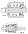
- Figur 3
- zeigt ein Schlagwerk in montierter Form ohne Amboss und
- Figur 4
- einen Längsschnitt durch ein Schlagwerk in montierter Form
- FIG. 1
- shows an impact mechanism of a striking screwdriver in exploded view
- FIG. 2
- shows an embodiment of the impact mechanism without flywheel in assembled representation
- FIG. 3
- shows a percussion in mounted form without anvil and
- FIG. 4
- a longitudinal section through a percussion in mounted form
Der Steuerteil 20 umfasst darüber hinaus Schlagbacken 24, die in axialer Richtung 26 über den eigentlichen Steuerteil in abtriebsseitige Richtung hinausstehen und mit in
Die Nuten 28 sind dabei vollständig innerhalb der Schwungmasse 22 angeordnet, so dass der Steuerteil 20 in radialer Richtung in keinem Betriebszustand über die Schwungmasse 22 hinausragt, sondern vollständig in diese aufgenommen ist.The
Zur Energiespeicherung und zur Erzeugung der Schlagenergie ist darüber hinaus eine Feder 30 vorgesehen, die zwischen Steuerteil 20 und Antriebswelle 10 angeordnet ist und die bei der Bewegung des Steuerteils 20 entlang der V-Nuten 14 zu einer Energiespeicherung gestaucht wird, wobei sich die Energie dann beim Trennen der Schlagbacken 24 von den Schlagbacken des Ambosses wieder entlädt. Darüber hinaus ist ein Axiallager 32 vorgesehen, dass zwischen Antriebswelle 10 und Schwungmasse 22 vorgesehen ist.For energy storage and to generate the impact energy beyond a
Durch diesen Aufbau wird erreicht, dass die Schwungmasse 22 keine axiale Bewegung durchführt und somit auch keine Vibration in diese Richtung verursacht und die Schwungmasse 22 der relativen Rotation zur Antriebswelle 10, die der Steuerteil 20 durchführt, folgen kann.By this construction it is achieved that the
Die Schlagbacken 34 des Ambosses 36 sind hierbei so gestaltet, dass diese vollständig in die Schwungmasse 22 aufgenommen werden und in radialer Richtung durch die Schwungmasse 22 umschlossen sind.The
Im Schraubfall kommt es nun zu einer Drehübertragung durch den Steuerteil 20, der durch die Antriebswelle 10 angetrieben wird, sowohl auf die Schwungmasse 22 aber auch über die Schlagbacken 24 und 34 auf den Amboss 36 und somit auf das Werkzeug. Kommt es nun zu einem ersten Blockieren des Werkzeugs und somit zu einem Blockieren des Ambosses 36, so führt der weitere Antrieb der Antriebswelle 10 dazu, dass der Steuerteil 20 in den V-Nuten relativ rotatorisch und axial in Richtung auf das antriebsseitige Ende 12 der Antriebswelle 10 bewegt wird und es so zu einem Trennen der Schlagbacken 24 von den Schlagbacken 34 kommt, bei gleichzeitigem Stauchen der Feder 30 und zu einer Speicherung der Energie in der Feder 30. Nach dem Trennen der Schlagbacken 24 von den Schlagbacken 34 kommt es dann zu einer Entspannung der Feder 30 und zu einer weiteren Bewegung in den V-Nuten 14, wobei die gespeicherte Energie der Feder 30 sich dann durch einen Schlag der Schlagbacken 24 gegen die Schlagbacken 34 entlädt. Bei der rotatorischen Bewegung wird darüber hinaus die Schwungmasse 22 mitgenommen, die jedoch keine axiale Bewegung durchführt, so dass die Schlagenergie durch die im Vergleich zum Steuerteil 20 größere Schwungmasse 22 bereitgestellt werden kann.When screwed it now comes to a rotation transmission through the
Zwischen der Schwungmasse 22 und der Antriebswelle 10 ist das Axiallager 32 vorgesehen, um eine rein rotatorische Relativbewegung der Schwungmasse 22 sicherzustellen. Durch die Anordnung der Schlagbacken 24 in der Schwungmasse 22 und damit das Eingreifen der Schlagbacken 34 in die Schwungmasse 22 liegen die Schlagbacken 24 auf voller Länge innerhalb der Nuten 28 der Schwungmasse 22. Dadurch vergrößert sich die Fläche, über die der Impuls von der Schwungmasse 22 auf den Steuerteil 20 übertragen wird. Außerdem liegen die Übertragungsflächen auf diese Weise näher am Trägheitsmittelpunkt der Schwungmasse 22.Between the
Besonders bevorzugt sind die Übertragungsflächen zwischen den Schlagbacken des Steuerteils 20 und des Ambosses 36 so ausgeführt, dass diese flächig gegeneinander anliegen. Alternativ können sie auch, wie in
Sofern nun gegenüber dem Stand der Technik die Schlagbacken 34 des Ambosses 36 hinsichtlich ihrer Länge in radialer Richtung verkürzt werden müssen, da sie nun innerhalb der Schwungmasse 22 zu liegen kommen, können diese entsprechend verbreitert werden, um die notwendige Steifigkeit bereitzustellen.If now compared to the prior art, the
Weitere Vorteile und Merkmale lassen sich den übrigen Unterlagen entnehmen.Further advantages and features can be found in the other documents.
Claims (12)
- An impact screwdriver having a drive motor for driving a drive shaft (10) and a drive shaft (38) which may be coupled to a tool holder as well as an impact mechanism, wherein the impact mechanism comprises an anvil (36) having first impact cheeks (34) coupled to the drive shaft (38) as well as a hammer which is guided on the drive shaft (10), wherein the hammer has second impact cheeks (24) which are in engagement with the first impact cheeks (34) for transmitting a rotational movement, in which the hammer comprises a centrifugal mass (22) and a control part (20), wherein the control part (20) carries the second impact cheeks (24) and rotates with the drive shaft (10) in non-impact mode and executes an axial and an additional rotational oscillation relative to the drive shaft (10) in impact mode, wherein the control part (20) transmits the rotation of the drive shaft (10) to the centrifugal mass (22) and is movably guided in the axial direction in the centrifugal mass (22) to realise the impact function and wherein the centrifugal mass (22) does not execute an axial movement, characterised in that the impact cheeks (24) of the control part (20) do not project beyond the centrifugal mass (22) in the axial direction.
- An impact screwdriver according to Claim 1, characterised in that the impact cheeks (34) of the anvil (36) dip fully or partially into the centrifugal mass (22) in the axial direction.
- An impact screwdriver according to one of the preceding claims, characterised in that the centrifugal mass (22) is connected to the control part (20) in torsion-resistant manner.
- An impact screwdriver according to one of the preceding claims, characterised in that the centrifugal mass (22) has a hollow-cylindrical shape.
- An impact screwdriver according to one of the preceding claims, characterised in that a spring for storing and releasing the impact energy is guided in the centrifugal mass (22) and the spring is supported against the centrifugal mass (22) and the control part (20).
- An impact screwdriver according to one of the preceding claim, characterised in that the impact mechanism is constructed as a V-groove impact mechanism, wherein V-grooves (14) are constructed in the drive shaft (10) and in the control part and are used for moving the control part (20) on the drive shaft (10) by way of balls (18) guided in the grooves (14).
- An impact screwdriver according to one of the preceding claims, characterised in that the centrifugal mass (22) has grooves in which ribs, which are particularly formed by the impact cheeks (24) of the control part (20), engage.
- An impact screwdriver according to Claim 7, characterised in that the ribs of the control part (20) complement the circumferential face of the centrifugal mass (22) with their circumferential face.
- An impact screwdriver according to one of the preceding claims, characterised in that the control part (20) is received in the centrifugal mass (22) in the radial direction and is surrounded thereby.
- An impact screwdriver according to one of the preceding claims, characterised in that an axial bearing (32) is provided between the centrifugal mass (22) and the drive shaft (10).
- An impact screwdriver according to one of the preceding claims, characterised in that the impact cheeks (34) of the anvil (36) and/or of the control part (20) have only a slight play with respect to the wall of the centrifugal mass (22) in the radial direction.
- An impact screwdriver according to one of the preceding claim, characterised in that the impact screwdriver is a cordless device.
Priority Applications (4)
| Application Number | Priority Date | Filing Date | Title |
|---|---|---|---|
| AT08011817T ATE554883T1 (en) | 2008-07-01 | 2008-07-01 | IMPACT WRENCH |
| EP08011817A EP2140977B1 (en) | 2008-07-01 | 2008-07-01 | Impact wrench |
| US12/485,217 US20100000749A1 (en) | 2008-07-01 | 2009-06-16 | Impact Wrench |
| CN200910151843.0A CN101618535B (en) | 2008-07-01 | 2009-07-01 | Impact wrench |
Applications Claiming Priority (1)
| Application Number | Priority Date | Filing Date | Title |
|---|---|---|---|
| EP08011817A EP2140977B1 (en) | 2008-07-01 | 2008-07-01 | Impact wrench |
Publications (2)
| Publication Number | Publication Date |
|---|---|
| EP2140977A1 EP2140977A1 (en) | 2010-01-06 |
| EP2140977B1 true EP2140977B1 (en) | 2012-04-25 |
Family
ID=39941594
Family Applications (1)
| Application Number | Title | Priority Date | Filing Date |
|---|---|---|---|
| EP08011817A Not-in-force EP2140977B1 (en) | 2008-07-01 | 2008-07-01 | Impact wrench |
Country Status (4)
| Country | Link |
|---|---|
| US (1) | US20100000749A1 (en) |
| EP (1) | EP2140977B1 (en) |
| CN (1) | CN101618535B (en) |
| AT (1) | ATE554883T1 (en) |
Families Citing this family (45)
| Publication number | Priority date | Publication date | Assignee | Title |
|---|---|---|---|---|
| EP2815850B1 (en) * | 2007-02-23 | 2016-02-03 | Robert Bosch Gmbh | Rotary power tool operable in either an impact mode or a drill mode |
| JP5405559B2 (en) * | 2008-04-22 | 2014-02-05 | ジェラード、グランド | Impact mechanism |
| DE102010030098A1 (en) * | 2010-06-15 | 2011-12-15 | Hilti Aktiengesellschaft | driving- |
| JP2012006101A (en) * | 2010-06-23 | 2012-01-12 | Makita Corp | Impact tool |
| TWM393379U (en) * | 2010-07-23 | 2010-12-01 | Top Gearbox Industry Co Ltd | Switching device for output configuration |
| DE102010038210A1 (en) | 2010-10-15 | 2012-04-19 | Wera-Werk Hermann Werner Gmbh & Co. Kg | Torque transmission device for use with a rotary impact driver |
| WO2012061176A2 (en) | 2010-11-04 | 2012-05-10 | Milwaukee Electric Tool Corporation | Impact tool with adjustable clutch |
| DE102011007691A1 (en) * | 2010-11-29 | 2012-05-31 | Robert Bosch Gmbh | Hammer mechanism |
| DE102011000710A1 (en) | 2011-02-14 | 2012-08-16 | Wera-Werk Hermann Werner Gmbh & Co. Kg | Torque transmission device in the form of a bit lining |
| WO2012170092A2 (en) * | 2011-03-11 | 2012-12-13 | Winnard Stanley D | Handheld drive device |
| US9469017B2 (en) | 2014-01-31 | 2016-10-18 | Ingersoll-Rand Company | One-piece power socket for an impact tool |
| US9566692B2 (en) * | 2011-04-05 | 2017-02-14 | Ingersoll-Rand Company | Rotary impact device |
| US9463557B2 (en) | 2014-01-31 | 2016-10-11 | Ingersoll-Rand Company | Power socket for an impact tool |
| JP5468570B2 (en) * | 2011-06-17 | 2014-04-09 | 株式会社マキタ | Impact tool |
| SE535919C2 (en) * | 2011-06-30 | 2013-02-19 | Atlas Copco Ind Tech Ab | Electrically powered tool |
| EP2556922B1 (en) * | 2011-08-09 | 2014-03-19 | C. & E. Fein GmbH | Power tool |
| DE102011089910A1 (en) * | 2011-12-27 | 2013-06-27 | Robert Bosch Gmbh | Hand tool device |
| DE102012209446A1 (en) * | 2012-06-05 | 2013-12-05 | Robert Bosch Gmbh | Hand machine tool device |
| CN103669137A (en) * | 2012-09-19 | 2014-03-26 | 蓬莱奥斯勃机械有限公司 | Hand-operated impact sleeper bolt wrench |
| US9227313B2 (en) * | 2012-11-27 | 2016-01-05 | Power Network Industry Co., Ltd. | Operation mode switching mechanism |
| JP6032041B2 (en) * | 2013-02-13 | 2016-11-24 | 日立工機株式会社 | Impact tools |
| EP3660711B1 (en) * | 2013-07-24 | 2021-09-01 | Promega Corporation | Processes for distribution and use of a mobile rfid container |
| US9539715B2 (en) * | 2014-01-16 | 2017-01-10 | Ingersoll-Rand Company | Controlled pivot impact tools |
| US9908208B2 (en) * | 2014-01-28 | 2018-03-06 | Tiger Tool International Incorporated | Offset press for removing wheel studs |
| US9751199B2 (en) | 2014-02-10 | 2017-09-05 | Tiger Tool International Incorporated | Disk brake wheel stud insertion and removal tool |
| DE102014209398A1 (en) * | 2014-05-19 | 2015-11-19 | Robert Bosch Gmbh | Impact body for a mechanical rotary impact mechanism |
| CN106573364B (en) * | 2014-07-31 | 2020-01-21 | 工机控股株式会社 | Impact tool |
| GB201421577D0 (en) | 2014-12-04 | 2015-01-21 | Black & Decker Inc | Drill |
| GB201421576D0 (en) | 2014-12-04 | 2015-01-21 | Black & Decker Inc | Drill |
| DE102015201573A1 (en) | 2015-01-29 | 2016-08-04 | Robert Bosch Gmbh | Impact device, in particular for an impact wrench |
| US10603770B2 (en) * | 2015-05-04 | 2020-03-31 | Milwaukee Electric Tool Corporation | Adaptive impact blow detection |
| US11065743B2 (en) | 2015-05-13 | 2021-07-20 | Wen Hung Chiang | Tool holder device |
| US20160332286A1 (en) * | 2015-05-13 | 2016-11-17 | Wen Hung Chiang | Tool holder device |
| US10471573B2 (en) * | 2016-01-05 | 2019-11-12 | Milwaukee Electric Tool Corporation | Impact tool |
| US20170197305A1 (en) * | 2016-01-10 | 2017-07-13 | Omnitek Partners Llc | Chisel Head Attachment For Electric Drills and Screw Drivers and the Like and Electric Chisels |
| TWI603815B (en) * | 2016-04-13 | 2017-11-01 | 優鋼機械股份有限公司 | Rotatable fastening device |
| CN111465469B (en) * | 2017-12-11 | 2021-11-23 | 阿特拉斯·科普柯工业技术公司 | Electric pulse tool |
| AU2019221782A1 (en) * | 2018-02-19 | 2020-10-08 | Milwaukee Electric Tool Corporation | Impact tool |
| US11135711B2 (en) | 2018-03-16 | 2021-10-05 | Tiger Tool International Incorporated | Retaining ring plier systems and methods |
| JP6979605B2 (en) * | 2018-05-11 | 2021-12-15 | パナソニックIpマネジメント株式会社 | Impact rotary tool |
| WO2020132587A1 (en) * | 2018-12-21 | 2020-06-25 | Milwaukee Electric Tool Corporation | High torque impact tool |
| US11623336B2 (en) * | 2019-08-22 | 2023-04-11 | Ingersoll-Rand Industrial U.S., Inc. | Impact tool with vibration isolation |
| CN211805940U (en) * | 2019-09-20 | 2020-10-30 | 米沃奇电动工具公司 | Impact tool and hammer head |
| US11815132B2 (en) | 2020-03-13 | 2023-11-14 | Tiger Tool International Incorporated | Bushing insertion systems and methods |
| CN112757206A (en) * | 2021-01-06 | 2021-05-07 | 四川九洲电器集团有限责任公司 | Impact-resistant automatic tightening wrench and self-tightening method thereof |
Family Cites Families (13)
| Publication number | Priority date | Publication date | Assignee | Title |
|---|---|---|---|---|
| US4811797A (en) * | 1987-10-21 | 1989-03-14 | Nauchno-Proizvodstvennoe Obiedinenie Po Mekhanizirovannomu Stroitelnomu Instrumentru I Otdelochnym Mashinam | Impact wrench |
| DE4301610C2 (en) | 1993-01-22 | 1996-08-14 | Bosch Gmbh Robert | Impact wrench |
| US6158526A (en) * | 1999-03-09 | 2000-12-12 | Snap-On Tools Company | Reversible impact mechanism with structure limiting hammer travel |
| JP4405900B2 (en) * | 2004-03-10 | 2010-01-27 | 株式会社マキタ | Impact driver |
| JP4468786B2 (en) * | 2004-10-28 | 2010-05-26 | 株式会社マキタ | Impact tools |
| US7308948B2 (en) * | 2004-10-28 | 2007-12-18 | Makita Corporation | Electric power tool |
| US20060237205A1 (en) * | 2005-04-21 | 2006-10-26 | Eastway Fair Company Limited | Mode selector mechanism for an impact driver |
| JP4597849B2 (en) * | 2005-12-01 | 2010-12-15 | 株式会社マキタ | Rotating hammer tool |
| US7168503B1 (en) * | 2006-01-03 | 2007-01-30 | Mobiletron Electronics Co., Ltd. | Power hand tool |
| DE202006014850U1 (en) * | 2006-09-27 | 2006-11-23 | Robert Bosch Gmbh | Mechanical beater for manual machine tool has impact body mounted axially movable and rotationally secured on drive shaft and an elastomer axial stop as ring-shaped spring element also mounted on drive shaft |
| US7494437B2 (en) * | 2007-01-04 | 2009-02-24 | Ting Kuang Chen | Impact power tool |
| DE202007011843U1 (en) | 2007-08-24 | 2008-01-03 | Jenn Feng Industrial Co., Ltd., Ping Chang City | Impact mechanism for a high torque motor tool |
| US7588093B2 (en) * | 2007-09-05 | 2009-09-15 | Grand Gerard M | Impact mechanism |
-
2008
- 2008-07-01 EP EP08011817A patent/EP2140977B1/en not_active Not-in-force
- 2008-07-01 AT AT08011817T patent/ATE554883T1/en active
-
2009
- 2009-06-16 US US12/485,217 patent/US20100000749A1/en not_active Abandoned
- 2009-07-01 CN CN200910151843.0A patent/CN101618535B/en not_active Expired - Fee Related
Also Published As
| Publication number | Publication date |
|---|---|
| US20100000749A1 (en) | 2010-01-07 |
| CN101618535B (en) | 2013-07-03 |
| ATE554883T1 (en) | 2012-05-15 |
| CN101618535A (en) | 2010-01-06 |
| EP2140977A1 (en) | 2010-01-06 |
Similar Documents
| Publication | Publication Date | Title |
|---|---|---|
| EP2140977B1 (en) | Impact wrench | |
| EP2140976B1 (en) | Impact wrench | |
| DE19505068C2 (en) | Striking tool | |
| EP2265420B1 (en) | Hand-held power tool for impacting driven tool attachments | |
| DE3932660C2 (en) | Impact drill with mechanical impact transmission | |
| EP2517835B1 (en) | Power tool | |
| DE102010062014B3 (en) | Hand tool | |
| EP2140978B1 (en) | Impact wrench | |
| DE2820128A1 (en) | CRAFT MACHINE | |
| WO2002020224A1 (en) | Tool mounting for a hand machine tool | |
| EP2612732A1 (en) | Handheld tool apparatus | |
| EP3638457B1 (en) | Hand-held power tool | |
| EP2612731B1 (en) | Handheld tool apparatus | |
| DE102010038210A1 (en) | Torque transmission device for use with a rotary impact driver | |
| EP2331298B1 (en) | Implement having an overrunning clutch | |
| EP2191939B1 (en) | Device for hand machine tool | |
| WO2009083307A1 (en) | Hand power tool having a gear arrangement comprising at least one pivotably supported intermediate shaft | |
| EP2132005B1 (en) | Rotary percussion mechanism | |
| EP1677950B1 (en) | Percussion device for a hand machine tool | |
| EP1618999B1 (en) | Hand held percussive tool or drill | |
| WO2009092366A2 (en) | Hammer mechanism for a power tool, particularly for a hand power tool such as an electric hammer drill or an impact wrench | |
| EP3829819A1 (en) | Handheld machine tool, in particular impact driver | |
| DE1299579B (en) | Transportable, motor-driven rotary impact device | |
| DE3500397A1 (en) | Electric percussion drilling machine | |
| WO2018224214A1 (en) | Clamping device and ultrasonic drill |
Legal Events
| Date | Code | Title | Description |
|---|---|---|---|
| PUAI | Public reference made under article 153(3) epc to a published international application that has entered the european phase |
Free format text: ORIGINAL CODE: 0009012 |
|
| AK | Designated contracting states |
Kind code of ref document: A1 Designated state(s): AT BE BG CH CY CZ DE DK EE ES FI FR GB GR HR HU IE IS IT LI LT LU LV MC MT NL NO PL PT RO SE SI SK TR |
|
| AX | Request for extension of the european patent |
Extension state: AL BA MK RS |
|
| 17P | Request for examination filed |
Effective date: 20100127 |
|
| AKX | Designation fees paid |
Designated state(s): AT BE CH DE FR GB LI |
|
| GRAP | Despatch of communication of intention to grant a patent |
Free format text: ORIGINAL CODE: EPIDOSNIGR1 |
|
| GRAS | Grant fee paid |
Free format text: ORIGINAL CODE: EPIDOSNIGR3 |
|
| GRAA | (expected) grant |
Free format text: ORIGINAL CODE: 0009210 |
|
| AK | Designated contracting states |
Kind code of ref document: B1 Designated state(s): AT BE CH DE FR GB LI |
|
| REG | Reference to a national code |
Ref country code: GB Ref legal event code: FG4D Free format text: NOT ENGLISH |
|
| REG | Reference to a national code |
Ref country code: CH Ref legal event code: EP |
|
| REG | Reference to a national code |
Ref country code: AT Ref legal event code: REF Ref document number: 554883 Country of ref document: AT Kind code of ref document: T Effective date: 20120515 |
|
| REG | Reference to a national code |
Ref country code: DE Ref legal event code: R096 Ref document number: 502008007036 Country of ref document: DE Effective date: 20120614 |
|
| BERE | Be: lapsed |
Owner name: METABOWERKE G.M.B.H. Effective date: 20120731 |
|
| REG | Reference to a national code |
Ref country code: CH Ref legal event code: PL |
|
| PLBE | No opposition filed within time limit |
Free format text: ORIGINAL CODE: 0009261 |
|
| STAA | Information on the status of an ep patent application or granted ep patent |
Free format text: STATUS: NO OPPOSITION FILED WITHIN TIME LIMIT |
|
| 26N | No opposition filed |
Effective date: 20130128 |
|
| PG25 | Lapsed in a contracting state [announced via postgrant information from national office to epo] |
Ref country code: LI Free format text: LAPSE BECAUSE OF NON-PAYMENT OF DUE FEES Effective date: 20120731 Ref country code: CH Free format text: LAPSE BECAUSE OF NON-PAYMENT OF DUE FEES Effective date: 20120731 |
|
| REG | Reference to a national code |
Ref country code: DE Ref legal event code: R097 Ref document number: 502008007036 Country of ref document: DE Effective date: 20130128 |
|
| PG25 | Lapsed in a contracting state [announced via postgrant information from national office to epo] |
Ref country code: BE Free format text: LAPSE BECAUSE OF NON-PAYMENT OF DUE FEES Effective date: 20120731 |
|
| REG | Reference to a national code |
Ref country code: AT Ref legal event code: MM01 Ref document number: 554883 Country of ref document: AT Kind code of ref document: T Effective date: 20130701 |
|
| PGFP | Annual fee paid to national office [announced via postgrant information from national office to epo] |
Ref country code: DE Payment date: 20140724 Year of fee payment: 7 |
|
| PG25 | Lapsed in a contracting state [announced via postgrant information from national office to epo] |
Ref country code: AT Free format text: LAPSE BECAUSE OF NON-PAYMENT OF DUE FEES Effective date: 20130701 |
|
| PGFP | Annual fee paid to national office [announced via postgrant information from national office to epo] |
Ref country code: GB Payment date: 20140721 Year of fee payment: 7 Ref country code: FR Payment date: 20140724 Year of fee payment: 7 |
|
| REG | Reference to a national code |
Ref country code: DE Ref legal event code: R119 Ref document number: 502008007036 Country of ref document: DE |
|
| GBPC | Gb: european patent ceased through non-payment of renewal fee |
Effective date: 20150701 |
|
| PG25 | Lapsed in a contracting state [announced via postgrant information from national office to epo] |
Ref country code: DE Free format text: LAPSE BECAUSE OF NON-PAYMENT OF DUE FEES Effective date: 20160202 Ref country code: GB Free format text: LAPSE BECAUSE OF NON-PAYMENT OF DUE FEES Effective date: 20150701 |
|
| REG | Reference to a national code |
Ref country code: FR Ref legal event code: ST Effective date: 20160331 |
|
| PG25 | Lapsed in a contracting state [announced via postgrant information from national office to epo] |
Ref country code: FR Free format text: LAPSE BECAUSE OF NON-PAYMENT OF DUE FEES Effective date: 20150731 |