EP2136268B1 - Image forming device - Google Patents
Image forming device Download PDFInfo
- Publication number
- EP2136268B1 EP2136268B1 EP09003407.5A EP09003407A EP2136268B1 EP 2136268 B1 EP2136268 B1 EP 2136268B1 EP 09003407 A EP09003407 A EP 09003407A EP 2136268 B1 EP2136268 B1 EP 2136268B1
- Authority
- EP
- European Patent Office
- Prior art keywords
- image forming
- door
- unit
- lock unit
- forming device
- Prior art date
- Legal status (The legal status is an assumption and is not a legal conclusion. Google has not performed a legal analysis and makes no representation as to the accuracy of the status listed.)
- Active
Links
- 229910052751 metal Inorganic materials 0.000 claims description 24
- 239000002184 metal Substances 0.000 claims description 24
- 239000011347 resin Substances 0.000 claims description 15
- 229920005989 resin Polymers 0.000 claims description 15
- 230000004044 response Effects 0.000 claims description 8
- 238000003825 pressing Methods 0.000 claims description 3
- 238000000034 method Methods 0.000 description 15
- 230000008569 process Effects 0.000 description 15
- 238000012546 transfer Methods 0.000 description 12
- 230000007246 mechanism Effects 0.000 description 6
- 230000033228 biological regulation Effects 0.000 description 4
- 239000003086 colorant Substances 0.000 description 3
- 238000004519 manufacturing process Methods 0.000 description 3
- 238000010276 construction Methods 0.000 description 2
- 230000002035 prolonged effect Effects 0.000 description 2
- 230000000717 retained effect Effects 0.000 description 2
- 208000027418 Wounds and injury Diseases 0.000 description 1
- 238000005299 abrasion Methods 0.000 description 1
- 239000003795 chemical substances by application Substances 0.000 description 1
- 230000006378 damage Effects 0.000 description 1
- 230000001419 dependent effect Effects 0.000 description 1
- 238000011161 development Methods 0.000 description 1
- 230000018109 developmental process Effects 0.000 description 1
- 229910052736 halogen Inorganic materials 0.000 description 1
- 150000002367 halogens Chemical class 0.000 description 1
- 238000010438 heat treatment Methods 0.000 description 1
- 230000003116 impacting effect Effects 0.000 description 1
- 208000014674 injury Diseases 0.000 description 1
- 238000003780 insertion Methods 0.000 description 1
- 230000037431 insertion Effects 0.000 description 1
- 238000012423 maintenance Methods 0.000 description 1
- 230000014759 maintenance of location Effects 0.000 description 1
- 238000012986 modification Methods 0.000 description 1
- 230000004048 modification Effects 0.000 description 1
- 229920000515 polycarbonate Polymers 0.000 description 1
- 239000004417 polycarbonate Substances 0.000 description 1
- 230000009467 reduction Effects 0.000 description 1
- 230000000452 restraining effect Effects 0.000 description 1
- 239000004065 semiconductor Substances 0.000 description 1
- 238000000926 separation method Methods 0.000 description 1
- 238000003860 storage Methods 0.000 description 1
- WFKWXMTUELFFGS-UHFFFAOYSA-N tungsten Chemical compound [W] WFKWXMTUELFFGS-UHFFFAOYSA-N 0.000 description 1
- 229910052721 tungsten Inorganic materials 0.000 description 1
- 239000010937 tungsten Substances 0.000 description 1
Images


Classifications
-
- G—PHYSICS
- G03—PHOTOGRAPHY; CINEMATOGRAPHY; ANALOGOUS TECHNIQUES USING WAVES OTHER THAN OPTICAL WAVES; ELECTROGRAPHY; HOLOGRAPHY
- G03G—ELECTROGRAPHY; ELECTROPHOTOGRAPHY; MAGNETOGRAPHY
- G03G21/00—Arrangements not provided for by groups G03G13/00 - G03G19/00, e.g. cleaning, elimination of residual charge
- G03G21/16—Mechanical means for facilitating the maintenance of the apparatus, e.g. modular arrangements
- G03G21/1604—Arrangement or disposition of the entire apparatus
- G03G21/1623—Means to access the interior of the apparatus
- G03G21/1633—Means to access the interior of the apparatus using doors or covers
-
- G—PHYSICS
- G03—PHOTOGRAPHY; CINEMATOGRAPHY; ANALOGOUS TECHNIQUES USING WAVES OTHER THAN OPTICAL WAVES; ELECTROGRAPHY; HOLOGRAPHY
- G03G—ELECTROGRAPHY; ELECTROPHOTOGRAPHY; MAGNETOGRAPHY
- G03G21/00—Arrangements not provided for by groups G03G13/00 - G03G19/00, e.g. cleaning, elimination of residual charge
- G03G21/16—Mechanical means for facilitating the maintenance of the apparatus, e.g. modular arrangements
- G03G21/1642—Mechanical means for facilitating the maintenance of the apparatus, e.g. modular arrangements for connecting the different parts of the apparatus
- G03G21/1647—Mechanical connection means
-
- G—PHYSICS
- G03—PHOTOGRAPHY; CINEMATOGRAPHY; ANALOGOUS TECHNIQUES USING WAVES OTHER THAN OPTICAL WAVES; ELECTROGRAPHY; HOLOGRAPHY
- G03G—ELECTROGRAPHY; ELECTROPHOTOGRAPHY; MAGNETOGRAPHY
- G03G21/00—Arrangements not provided for by groups G03G13/00 - G03G19/00, e.g. cleaning, elimination of residual charge
- G03G21/16—Mechanical means for facilitating the maintenance of the apparatus, e.g. modular arrangements
- G03G21/18—Mechanical means for facilitating the maintenance of the apparatus, e.g. modular arrangements using a processing cartridge, whereby the process cartridge comprises at least two image processing means in a single unit
- G03G21/1839—Means for handling the process cartridge in the apparatus body
- G03G21/1842—Means for handling the process cartridge in the apparatus body for guiding and mounting the process cartridge, positioning, alignment, locks
- G03G21/1853—Means for handling the process cartridge in the apparatus body for guiding and mounting the process cartridge, positioning, alignment, locks the process cartridge being mounted perpendicular to the axis of the photosensitive member
-
- G—PHYSICS
- G03—PHOTOGRAPHY; CINEMATOGRAPHY; ANALOGOUS TECHNIQUES USING WAVES OTHER THAN OPTICAL WAVES; ELECTROGRAPHY; HOLOGRAPHY
- G03G—ELECTROGRAPHY; ELECTROPHOTOGRAPHY; MAGNETOGRAPHY
- G03G2221/00—Processes not provided for by group G03G2215/00, e.g. cleaning or residual charge elimination
- G03G2221/16—Mechanical means for facilitating the maintenance of the apparatus, e.g. modular arrangements and complete machine concepts
- G03G2221/1651—Mechanical means for facilitating the maintenance of the apparatus, e.g. modular arrangements and complete machine concepts for connecting the different parts
- G03G2221/1654—Locks and means for positioning or alignment
-
- G—PHYSICS
- G03—PHOTOGRAPHY; CINEMATOGRAPHY; ANALOGOUS TECHNIQUES USING WAVES OTHER THAN OPTICAL WAVES; ELECTROGRAPHY; HOLOGRAPHY
- G03G—ELECTROGRAPHY; ELECTROPHOTOGRAPHY; MAGNETOGRAPHY
- G03G2221/00—Processes not provided for by group G03G2215/00, e.g. cleaning or residual charge elimination
- G03G2221/16—Mechanical means for facilitating the maintenance of the apparatus, e.g. modular arrangements and complete machine concepts
- G03G2221/1678—Frame structures
- G03G2221/1684—Frame structures using extractable subframes, e.g. on rails or hinges
Definitions
- the present invention relates to an image forming device having an image forming system for forming an image on a recording medium. More specifically, the present invention relates to an image forming device having an image forming unit detachably supported by a frame, the image forming unit being a major part of the image forming system.
- an image forming system is supported to a frame, and an image forming unit which is a part of the image forming system is detachably mounted on the frame.
- an image forming unit which is a part of the image forming system is detachably mounted on the frame.
- developing cartridges and photosensitive drums are detachably mounted on a frame as an integral image forming unit. In this case, improved maintenance efficiency can be obtained because four developing cartridges can be integrally removed from a frame.
- JP 11 202725 A discloses an image forming device wherein a main body front cover is provided with a rotation supporting point provided at a part of a main body case.
- a main body front cover lock lever is attached to the cover and made turnable with a supporting point as the center.
- a force is exerted on the lever by a main body front cover lock lever pressing part utilizing elasticity of a resin integrally provided.
- a main body front cover lock shaft is provided on a fixation device lock lever, and a main body front cover lock lever lock part is caught by the lock shaft in a state where the cover is closed.
- a process cartridge is provided with a part to be held.
- the image forming device main body is provided with a reference surface for positioning the process cartridge in a loaded state, a holding member which is rotatably supported by the image forming device main body and provided with a first surface and a second surface and an urging member for urging the holding member.
- the holding member is constituted so as to have a first position where the part of the process cartridge is pressurized and held by the first surface in the process cartridge loading direction and a second position where the part of the process cartridge is pressurized by the second surface in the process cartridge unloading direction.
- JP 2002-162797 A there is known an image forming device wherein a cartridge is extruded from a set position to a retreated position by opening a cover.
- JP 09- 281840 A there is known a printer wherein a cam mechanism is used to separate a heating roller from a pressure roller in a fixing unit when opening an upper main body of the printer.
- Japanese laid open patent application publication No. 8-220824 discloses an image forming device in which a door is open when removing and inserting an image forming unit, and movement of the door is interlocked with a support assembly that supports the image forming unit so that the image forming unit is positioned at a prescribed location in the image forming device in response to closure of the door.
- the image forming unit may be displaced from the prescribed location when the door is open. Accordingly, a lock mechanism is required for maintaining the door in a closed state during image forming operation.
- the number of parts and components to provide such mechanism increases and configuration of the device becomes more complex if a mechanism for positioning an image forming unit and the above lock mechanism are provided in association with the door.
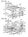
- the laser printer 100 includes a main frame 200 and an image forming system 300.
- the main frame 200 is formed substantially in a box shape.
- An outer cover (not shown) formed of resin is formed over an outer surface of the main frame 200.
- the image forming system 300 includes an image forming unit 350 capable of being pulled out of the main frame 200 and detachably mounted on the main frame 200.
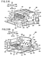
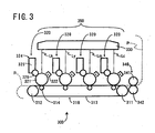
- the image forming system 300 includes a belt unit 310 (a conveyer unit), a scanner unit 330, a fixing unit 340, and an image forming unit 350 including four process units 320 and a drum sub unit 351 ( Figs. 2(A) and 2(B) ).
- the belt unit 310 includes a drive roller 311, a driven roller 312, and an endless conveying belt (transfer belt) 313 stretched around the drive roller 311 and the driven roller 312, and four transfer rollers 314.
- the process units 320 constitute a direct transfer tandem type color image forming system.
- the process units 320 are disposed above the belt unit 310, and juxtaposed in the front-to-rear direction in order of the colors black (K), yellow (Y), magenta (M), and cyan (C) from the front side of the laser printer 100.
- Each of the process units 320 is detachably stored in each of four storages (not shown) provided in the drum sub unit 351 constituting a frame of the image forming unit 350.
- Each of the process units 320 includes a photosensitive drum 321 (an image bearing member), a scorotron charger 322, and a developing cartridge 324, and a developing roller 326.
- the photosensitive drum 321 includes a grounded drum body formed of metal, and a positively chargeable photosensitive layer formed of polycarbonate formed on an outer surface of the drum body.
- the scorotron charger 322 is disposed diagonally above and rearward of the photosensitive drum 321 and opposes the photosensitive drum 321 at a prescribed distance so as not to contact the same.
- the scorotron charger 322 has a charging wire formed of tungsten to generate corona discharge so that the surface of the photosensitive drum 321 can be uniformly charged to have a positive polarity.
- Each of the developing cartridges 324 defines therein a toner chamber 325 in which a positively chargeable, nonmagnetic, single-component toner in one of the colors black, cyan, magenta and yellow as a developing agent is retained.
- the developing roller 326 is provided between the photosensitive drum 321 and the toner chamber 325 for supplying toner positively tribocharged to the photosensitive drum 321.
- the transfer rollers 314 are respectively disposed opposite to the photosensitive drums 321.
- the conveying belt 313 is pinched between the transfer rollers 314 and the photosensitive drums 321.
- the conveying belt 313 moves circularly in a clockwise direction the same as the direction that the drive roller 311 rotates.
- a sheet supply tray (not shown) is provided in a lower section of the main frame 200.
- a sheet P as a recording medium is supplied to a surface of the conveying belt 313 by a supply roller (not shown) from the sheet supply tray.
- the sheet P on the conveying belt 313 moves past the photosensitive drums 321 and is conveyed to the rear side of the laser printer 100.
- the scanner unit 330 is disposed above the process units 320.
- the scanner unit 330 includes a semiconductor laser (not shown) adapted for generating laser beams Lk, Ly, Lm, and Lc corresponding to image data of each color, and a polygon mirror (not shown) deflecting a laser beam L for scanning over the photosensitive drums 321 and exposes the same to the laser beam.
- the surface of each photosensitive drum 321 is uniformly charged to have a positive polarity by the scoroton charger 322 when rotating. Then, the surface is subjected to high speed scan of the laser beam L, so that an electrostatic latent image corresponding to an image to be formed on the sheet P is formed on the surface.
- the toner images formed on the surfaces of the photosensitive drums 321 are sequentially transferred onto the sheet P by a transfer bias with a negative polarity applied to the transfer rollers 314 by a constant current control, each time the sheet P conveyed on the conveying bet 313 passes between each photosensitive drum 321 and each transfer roller 314.
- the sheet P bearing the toner image is then conveyed to the fixing unit 340 disposed rearward of the belt unit 310.
- the fixing unit 340 includes a heat roller 341 and a pressure roller 342.
- the heat roller 341 is drivingly rotatable and includes a heat source such as a halogen lamp.
- the pressure roller 342 is disposed below the heat roller 341 and opposes the heat roller 341 to press the same.
- the pressure roller 342 rotates in association with rotation of the heat roller 341.
- the sheet P on which the toner image with the four colors is formed is heated while conveyed between the heat roller 341 and the pressure roller 342, so that the toner image is thermally fixed on the sheet P.
- the sheet P on which the toner image has been fixed is conveyed by several rollers (not shown) and discharged to a discharge tray (not shown) provided in a top surface of the laser printer 100.
- the drum sub unit 351 constitutes the image forming unit 350, and is adapted to retain four process units 320.
- the drum sub unit 351 retaining the four process units 320 is detachably installable to the main frame 200 as a detachable image forming unit 350.
- the drum sub unit 351 has a front side provided with a support shaft 352 extending along a front frame section of the drum sub unit 351 in a right-to-left direction (lateral direction). Each end of the support shaft 352 laterally outwardly protrudes from right and left side frame sections of the drum sub unit 351.
- the support shaft 352 functions as a second positioning part.
- the right and left side frame sections of the drum sub unit 351 has rear end portions formed with cutout parts 353.
- Each cutout part 353 is open at a rear end face of each side frame section, and extends frontward.
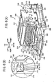
- the main frame 200 includes a pair of metal frames 210, and a pair of resin frames 250 positioned immediately below the pair of metal frames 210 for supporting the same.
- the pair of metal frames 210 is adapted for supporting the scanner unit 330 and the image forming unit 350.
- the scanner unit 330 has a scanner plate (not shown) fixed by screws on an upper portion of the metal frames 210. Thus, the scanner unit 330 can be supported horizontally in the upper portion of the metal frames 210.
- Each lower edge of the metal frames 210 is in contact with each upper edge of the resin frames 250.
- Each of the resin frames 250 has a laterally outward portion protruding laterally outward of the metal frames 210, and the laterally outward portion is fixed to the metal frames 210 by screws 251.
- a front beam 252 is fixed by screws to bottom surfaces of the resin frames 250 at a front side thereof.
- a rear beam 253 is fixed by screws to the bottom surfaces of the resin frames 250 at a rear side thereof.
- the resin frames 250 are connected each other by the front beam 252 and the rear beam 253.
- Each side frame section of the main frame 200 has a front end formed with a hole 211 allowing the support shaft 352 to extend therethrough.
- each end of the support shaft 352 is brought into engagement with each hole 211.
- each front portion of each side frame section is bent laterally outward so as to form a flange 212, and the hole 211 is formed in the flange 212 to form an L-shape. That is, the hole 211 has a front opening and extends rearward.
- the hole 211 defines a lower surface 211a extending horizontally and rearward.
- Each end portion of the support shaft 352 is placed on the lower surfaces 211a so that the front end of the image forming unit 350 is subjected to positioning in a vertical direction.
- the lower surface 211a functions as a first positioning part or as an end face.
- the hole 211 also defines an upper slant surface 211b (a second shift portion) extending diagonally rearward and downward, and a rear surface 211c extending vertically.
- a reference shaft 220 bridges between the pair of metal frames 210 at a rear portion thereof, so that the cutout parts 353 is engageable with the reference shaft 220 when the image forming unit 350 is mounted on the main frame 200.
- the engagement defines the position of the rear end of the image forming unit 350 in the vertical direction and in the front-to-rear direction.
- each metal frame 210 is formed with a square hole 213 at a rear portion thereof, and each end portion of the reference shaft 220 extends through the square hole 213.
- Each end portion of the reference shaft 220 is urged by a linear spring 230 towards a lower rear corner of the square hole 213 for positioning.
- the holes 211 and the square holes 213 are concurrently formed on the metal frames 210 by a press forming together with screw holes (not shown) for fixing the scanner unit 330. Further, portions of the metal frame 210 around the screw holes, the holes 211, and the square holes 213 are not bent but flat. Therefore, enhanced positional accuracy between the scanner unit 330 and the image forming unit 350 can result in the laser printer 100, and eventually, positional accuracy between the scanner unit 330 and each of the photosensitive drums 321 can be improved. Accordingly, an accurate image can be formed.
- the drum sub unit 351 is guided by a guide (not shown) so that the reference shaft 220 can fit with the cutout parts 353 for assembly of the image forming unit 350 into the main frame 200.
- a guide structure is disclosed in laid open Japanese patent application publication No. 2007-121983 . Accordingly, a detailed explanation will be omitted.
- each metal frame 210 is orthogonally bent outward.
- a scanner cover 241 formed of metal and covering an upper front half portion of the scanner unit 330 is fixed to the upper end portion by screws.
- the belt unit 310 described above is detachably mounted between the pair of resin frames 250.
- a door 400 is pivotably movable between a vertical closed position for closing a front space defined between the pair of metal frames 210 and a horizontal open position for exposing the image forming unit 350 to an atmosphere through the pair of metal frames 210.
- the resin frame 250 has an upper front portion provided with a pivot shaft 255 protruding laterally outwardly.
- a generally sector-shaped eccentric cam plate 410 is attached to each pivot shaft 255 and pivotally movable about an axis thereof.
- the cam plate 410 has an arcuate cam surface, and has a configuration such that a radius between the arcuate cam surface and the axis of the pivot shaft 255 is gradually reduced toward the door 400.
- the door 400 is integrally with each of the cam plates 410 at a radially shortest end thereof.
- Each of the cam plates 410 is positioned rearward of the door 400 (a side of the main frame 200) when the door 400 is at its closed position.
- the door 400 has a hook 420 protruding from an inner surface thereof (a rear side of the door 400 when the door 400 is at its closed position).
- each flange 212 is formed with upper and lower vertically elongated slots 214 vertically aligned with each other. Each lower end portion of each slot 214 has a width greater than that of the remaining portion thereof.
- a lock member 500 is vertically slidably movably supported to the each flange 212. That is, each lock member 500 is positioned on a rear surface of each flange 212.
- the lock member 500 includes engagement portions 501 engaged with the slots 214, so that the lock member 500 is vertically slidable on the rear surface of the flange 212.
- the engagement portions 501 have an enlarged head positioned in front of each flange 212.
- the lock member 500 is made of a resin, so that its hardness is lower than that of the metal frame 210 and the support shaft 352 those made from a metal.
- a lower end of the lock member 500 is formed with a chamfered portion 502 for providing a smooth contact with the arcuate cam surface of the cam plate 410, so that the lock member 500 can move upward and downward in association with the movement of the door 400.
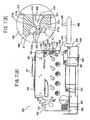
- the lock member 500 descends when the door 400 is at its closed position as shown in Fig. 1 (A) , since the chamfered portion 502 is in contact with the smaller radius portion of the cam surface.
- the lock member 500 ascends when the door 400 is at its open position as shown in Fig. 2(A) , since the chamfered portion 502 is in contact with the greater radius portion of the cam surface.
- each of the lock member 500 has a recessed portion 510 at a portion superposed with the hole 211.
- the recessed portion 510 has a front opening and is cutout in an inner side of the lock member 500.
- an outer surface of the lock member 500 is partially omitted for simplicity in order to clarify the shape of the recessed portion 510.
- the recessed portion 510 defines a lower surface and an upper surface extending rearward.
- the lower surface has a first inclined surface 511, a horizontal flat surface 512, and a protruding part 513.
- the first inclined surface 511 inclines upward toward a bottom end of the recessed portion 510.
- the horizontal flat surface 512 functioning as a shift portion or as a restraining portion, is connected from a rear end of the first inclined surface 511.
- the protruding part 513 protrudes upward from the rear end of the horizontal flat surface 512 and is generally rectangular-shaped.
- the protruding part 513 has a vertical surface 513a connected to the horizontal flat surface 512, and an upper surface 513b connected to the vertical surface 513a. A rear end of the upper surface 513b is connected to a bottom surface of the recessed portion 510.
- the upper surface has a second inclined surface 516 and a third inclined surface 517.
- the second inclined surface 516 slightly inclines downward toward the bottom of the recessed portion 510.
- the third inclined surface 517 functioning as a pressure portion, is connected to the rear end of the second inclined surface 516 and inclines upward toward the bottom of the recessed portion 510. Angle between the second and third inclined surfaces 516 and 517 is approximately 135 degrees.
- each lock member 500 has a locking hook 520 which is integrally formed with the lock member 500.
- the locking hook 520 is engaged with the hook 420 of the door 400 when the door 400 is at its closed position. This engagement can maintain the closing state of the door 400.
- the flange 212 is formed with a hole 215 allowing the hook 420 to extend therethrough as shown in Fig. 6(A) . Thus, the hook 420 is engagable with the locking hook 520.
- the locking hook 520 is formed of resin and is integrally with a main body 540 of the lock member 500 via a U-shaped leaf spring plate 521.
- a coil spring 530 is interposed between an upper surface of the main body 540 and the locking hook 520.
- a first regulation hook 543 protrudes upward from the upper surface of the main body 540, and a second regulation hook 523 protrudes downward from a lower portion of the locking hook 520.
- the first regulation hook 543 is engageable with the second regulation hook 523 so that excessive urging of the locking hook 520 toward the hook 420 by the biasing force of the coil spring 530 can be restrained.
- a combination of the main body 540, the U-shaped leaf spring plate 521, the hooks 520, 523, 543 and the coil spring 530 is referred to as a lock unit.
- Figs. 7 (A) and 7(B) the outer surface of the lock member 500 is partially omitted, in the same manner as Figs. 5(A) and 5(B) .
- Figs. 6(B) and 7(B) when the door 400 is at its open position and the lock member 500 moves upward, the first inclined surface 511 and the horizontal flat surface 512 of the recessed portion 510 is moved to a position above the lower surface 211a of the hole 211.
- the upper surface, 513b of the protruding part 513 is positioned above a lower part of the upper slant surface 211b of the hole 211, and the first inclined surface 511 is positioned below the upper slant surface 211b and above the lower surface 211a.
- the support shaft 352 When the door 400 is at its open position for detachment or attachment of the image forming unit 350 relative to the main frame 200, the support shaft 352 is not in direct contact with the lower surface 211a because the first inclined surface 511 and the horizontal flat surface 512 are disposed above the lower surface 211a, even if the image forming unit 350 is slammingly pushed into the main frame 200. Further, since the upper surface 513b of the protruding part 513 is disposed above the lower portion of the upper slant surface 211b, the support shaft 352 can be brought into contact with a lower portion of the vertical surface 513a of the protruding part 513, i.e., base end portion thereof.
- the image forming unit 350 can be restrained from being excessively inserted into rearward. It should be noted that the cutout parts 353 are not fully engaged with the reference shaft 220 when the support shaft 352 is in contact with the base end portion of the protruding part 513. Hence, the reference shaft 220 can be restrained from being in impacting contact with the cutout parts 353 at an initial insertion phase of the image forming unit 350 into the main frame 200.
- the third inclined surface 517 is positioned above the support shaft 352 if the support shaft 352 is placed on the horizontal flat surface 512.
- the lock member 500 is moved downward and the hook 420 extends into the hole 215 and is brought into engagement with the locking hook 520.
- the third inclined surface 517 presses the support shaft 352 downward and rearward as shown in Fig. 5(B) because of the biasing force transmitted from the hook 420, the U-shaped leaf spring plate 521, the locking hook 520, and the coil spring 530.
- the first inclined surface 511, the horizontal flat surface 512, and the protruding part 513 are positioned below the lower surface 211a.
- the support shaft 352 is in direct contact with the lower surface 211a of the hole 211, and the image forming unit 350 as a whole can further be pressed rearward.
- the cutout parts 353 can be engaged with the reference shaft 220.
- the image forming unit 350 is positioned at a prescribed location in the main frame 200 so that an accurate image can be formed on the sheet P.
- the lower surface 211a is moved to a position below the upper surface 513b, so that the support shaft 352 will be transferred from the lower surface 211a to the upper surface 513b.
- the support shaft 352 is rolled down onto the horizontal flat surface 512 from the upper surface 513b of the protruding part 513 because of the urging force from the upper slant surface 211b. Since the lock member 500 is moved upward, the support shaft 352 on the horizontal flat surface 512 is lifted above the lower surface 211a of the hole 211.
- the image forming unit 350 is moved frontward by a length of the upper surface 513b, and is moved upward by a vertical distance between the lower surface 211a and the horizontal flat surface 512 as shown in Fig. 7(B) .
- This frontward and upward movement facilitates removal of the image forming unit 350.
- the photosensitive drums 321 are moved away from the conveying belt 313.
- a guide mechanism described in laid open Japanese patent application publication No. 2007-121983 can be provided in the laser printer 100 for positively moving the image forming unit 350 upward when the image forming unit 350 is being pulled out frontward. In the latter case, the photosensitive drums 321 can surely be moved away from the conveying belt 313.
- the third inclined surface 517 is provided in the lock member 500 formed integrally with the locking hook 520 for maintaining the door 400 in a closed state.
- the structure of the laser printer 100 can be simplified by reducing the number of parts and components, and eventually, cost reduction for manufacturing the laser printer 100 can be attained.
- engagement between the support shaft 352 and the lower surface 211a of the hole 211 formed on the metal frame 210 can provide positioning of the image forming unit 350. Further, the support shaft 352 is directly pressed by the third inclined surface 517. The image forming unit 350 can be subjected to proper positioning relative to the main frame 200. Accordingly, the laser printer 100 in the present embodiment is capable of forming an accurate image on the sheet P.
- the protruding part 513 and the horizontal flat surface 512 integrally formed in the lock member 500 facilitates separation of the photosensitive drums 321 from the conveying belt 313 when the door 400 is at its open position.
- the photosensitive drums 321 can be protected against any scratch or injury because no frictional contact with the conveyer belt 313 during detachment work of the image forming unit 350.
- the first inclined surface 511 and the horizontal flat surface 512 are positioned above the lower surface 211a of the hole 211 when the door 400 is open. Therefore, direct abutment of the support shaft 352 onto the lower surface 211a can be restrained. Accordingly, frictional wearing of the lower surface 211a and the support shaft 352 can be avoided to enable stabilized image forming operation for a prolonged period.
- the first inclined surface 511, the horizontal flat surface 512 and the protruding part 513 are retracted to a position lower than the lower surface 211a when the door 400 is closed.
- abutment between the support shaft 352 and the lower surface 211a can be provided, so that the image forming unit 350 can be subjected to positioning at a given position within the frame 200.
- the support shaft 352 is pressed by the third inclined surface 517, stabilized positioning can be made. Accordingly, performance of image forming operation can be further ensured.
- the first inclined surface 511, the horizontal flat surface 512 and the protruding part 513 those preventing the support shaft 352 from directly abutting on the lower surface 211a are provided integrally with the locking member 500 having the locking hook 520 that maintains the door 400 in its closed position. Accordingly, a simplified construction can be provided eliminating mechanical parts and components, thereby lowering production cost. Further, positioning of the image forming unit 350 is attained by the engagement between the support shaft 352 and the lower surface 211a of the hole 211 formed in the metal frame 200 and, the third inclined surface 517 directly presses the support shaft 352. Accordingly, sufficient positioning of the image forming unit 350 relative to the frame 200 is achievable. Thus, the resultant laser printer 100 can produce accurate visible image on the sheet P.
- the present invention can be applied to several types of an image forming device, such as, a monochromatic laser printer, a facsimile machine, an ink jet printer, and a copying machine.
- the image forming unit 350 is detachable from the main frame 200.
- the present invention is not only available for the image forming unit of complete detachment type but also for an image forming unit of non-detachable type. In the latter case, the image forming unit can be pulled out and inserted into the main frame without any detachment from the main frame.
- the image forming unit 350 can be pulled out of the main frame 200 to the extent that each of the developing cartridges 324 is exchangeable.
- the developing cartridges 324 and the photosensitive drums 321 are assembled in a single process cartridge unit.
- a cartridge including only the developing cartridge is also available in the present invention.
- the pressure portion (the third inclined surface 517) can press any part of the image forming unit other than the support shaft 352.
- direct pressure applied by the third inclined surface 517 against the support shaft 352 can provide accurate positioning of the image forming unit 350 with respect to the main frame 200.
- the lock member 500 is engaged with the support shaft 352 for positioning the image forming unit 350.
- the lock member 500 can be engaged with a part or component of the image forming unit 350 other than the support shaft 352. Still however, as long as the locking member 500 made from a resin is provided where the engagement surface of the locking member 500 is moved upward exceeding the lower surface 211a in response to the opening stroke of the door 400 in order to protect the lower surface 211a, the support shaft 352 would be a desirable component to be brought into abutment with the engagement surface.
- frictional wearing of the support shaft 352 can be efficiently reduced because the locking member 500 is made from the resin. Consequently, frictional abrasion of the lower surface 211a and the support shaft 352 can further be reduced to provide desirable image forming operation for a prolonged period of time.
- the above-described embodiment pertains to the direct transfer tandem type color image forming system where the sheet P is conveyed by the conveying belt 313 so as to sequentially pass through the photosensitive drums 321 for directly receiving toner images from the photosensitive drums 321 onto the sheet P.
- the present invention is also available for an intermediate transfer tandem type color image forming system where the toner images formed on the photosensitive drums 321 are transferred onto an intermediate transfer belt, and then, the toner images transferred onto the intermediate transfer belt are transferred onto the sheet P.
Landscapes
- Physics & Mathematics (AREA)
- General Physics & Mathematics (AREA)
- Engineering & Computer Science (AREA)
- Computer Vision & Pattern Recognition (AREA)
- Electrophotography Configuration And Component (AREA)
Applications Claiming Priority (1)
| Application Number | Priority Date | Filing Date | Title |
|---|---|---|---|
| JP2008160741A JP4586894B2 (ja) | 2008-06-19 | 2008-06-19 | 画像形成装置 |
Publications (3)
| Publication Number | Publication Date |
|---|---|
| EP2136268A2 EP2136268A2 (en) | 2009-12-23 |
| EP2136268A3 EP2136268A3 (en) | 2010-09-22 |
| EP2136268B1 true EP2136268B1 (en) | 2016-01-06 |
Family
ID=41056995
Family Applications (1)
| Application Number | Title | Priority Date | Filing Date |
|---|---|---|---|
| EP09003407.5A Active EP2136268B1 (en) | 2008-06-19 | 2009-03-09 | Image forming device |
Country Status (4)
| Country | Link |
|---|---|
| US (1) | US8160472B2 (zh) |
| EP (1) | EP2136268B1 (zh) |
| JP (1) | JP4586894B2 (zh) |
| CN (1) | CN101609296B (zh) |
Families Citing this family (14)
| Publication number | Priority date | Publication date | Assignee | Title |
|---|---|---|---|---|
| JP4586894B2 (ja) | 2008-06-19 | 2010-11-24 | ブラザー工業株式会社 | 画像形成装置 |
| JP4596047B2 (ja) | 2008-06-19 | 2010-12-08 | ブラザー工業株式会社 | 画像形成装置 |
| JP5369882B2 (ja) * | 2009-05-14 | 2013-12-18 | ブラザー工業株式会社 | 画像形成装置 |
| JP5051268B2 (ja) * | 2010-04-28 | 2012-10-17 | ブラザー工業株式会社 | カバー開閉機構及び画像処理装置 |
| JP5787612B2 (ja) * | 2010-06-22 | 2015-09-30 | キヤノン株式会社 | 画像形成装置 |
| JP5870683B2 (ja) * | 2011-12-26 | 2016-03-01 | 富士ゼロックス株式会社 | 記録材処理装置 |
| JP5919852B2 (ja) | 2012-01-31 | 2016-05-18 | ブラザー工業株式会社 | 画像形成装置 |
| JP5949226B2 (ja) | 2012-07-03 | 2016-07-06 | ブラザー工業株式会社 | 画像形成装置 |
| JP5910359B2 (ja) | 2012-07-03 | 2016-04-27 | ブラザー工業株式会社 | 画像形成装置 |
| JP5949377B2 (ja) | 2012-09-21 | 2016-07-06 | ブラザー工業株式会社 | 画像形成装置 |
| JP6119582B2 (ja) * | 2013-11-15 | 2017-04-26 | ブラザー工業株式会社 | 画像形成装置 |
| JP6142796B2 (ja) * | 2013-12-24 | 2017-06-07 | ブラザー工業株式会社 | 画像形成装置 |
| JP6098554B2 (ja) | 2014-03-11 | 2017-03-22 | ブラザー工業株式会社 | 画像形成装置 |
| JP6708443B2 (ja) * | 2016-03-01 | 2020-06-10 | キヤノン株式会社 | ロック機構及び画像形成装置 |
Family Cites Families (43)
| Publication number | Priority date | Publication date | Assignee | Title |
|---|---|---|---|---|
| US1872321A (en) * | 1931-01-30 | 1932-08-16 | Bassick Co | Hood catch |
| US2470591A (en) * | 1948-10-06 | 1949-05-17 | Paul A Viola | Window control device |
| US4833547A (en) * | 1987-04-20 | 1989-05-23 | Nissei Opto Co., Ltd. | Portable facsimile equipment and the cover body closing device |
| EP0331324B1 (en) * | 1988-03-02 | 1993-09-08 | Canon Kabushiki Kaisha | Image forming apparatus usable with process cartridge detachably mountable thereto |
| JP2628236B2 (ja) * | 1991-05-20 | 1997-07-09 | シャープ株式会社 | 画像形成装置 |
| US5608498A (en) * | 1995-02-03 | 1997-03-04 | Konica Corporation | Image forming apparatus in which at least an image carrying member and plural exposure means are constructed in a single body |
| JPH08220824A (ja) * | 1995-02-17 | 1996-08-30 | Konica Corp | カラー画像形成装置 |
| JPH0916056A (ja) * | 1995-06-30 | 1997-01-17 | Canon Inc | プロセスカートリッジ及び画像形成装置 |
| JP3562779B2 (ja) * | 1996-04-17 | 2004-09-08 | 桂川電機株式会社 | 画像形成装置 |
| JPH09297631A (ja) * | 1996-04-30 | 1997-11-18 | Toshiba Corp | 携帯形機器 |
| JPH11202725A (ja) * | 1998-01-19 | 1999-07-30 | Ricoh Co Ltd | 前カバー固定機構 |
| JP2000181329A (ja) * | 1998-12-18 | 2000-06-30 | Canon Inc | 画像形成装置 |
| JP4458642B2 (ja) * | 1999-08-31 | 2010-04-28 | キヤノン株式会社 | 画像形成装置 |
| JP2002162797A (ja) * | 2000-11-28 | 2002-06-07 | Funai Electric Co Ltd | 画像形成装置 |
| US6550838B2 (en) * | 2001-08-02 | 2003-04-22 | Club Car, Inc. | Cargo box tailgate assembly |
| KR100462613B1 (ko) | 2002-07-09 | 2004-12-20 | 삼성전자주식회사 | 인쇄기의 감광유닛 및 전사유닛 교환 시스템 |
| JP2004294809A (ja) * | 2003-03-27 | 2004-10-21 | Sharp Corp | キャビネットの開放構造、シート部材搬送手段を有する装置及び画像形成装置 |
| JP4529391B2 (ja) * | 2003-07-22 | 2010-08-25 | ブラザー工業株式会社 | 画像形成装置におけるカバーの位置決め方法 |
| US7266327B2 (en) | 2003-07-25 | 2007-09-04 | Brother Kogyo Kabushiki Kaisha | Image-forming device having a removable process cartridge |
| JP4298479B2 (ja) | 2003-11-27 | 2009-07-22 | キヤノン株式会社 | 画像形成装置 |
| JP4306509B2 (ja) | 2004-03-29 | 2009-08-05 | ブラザー工業株式会社 | 画像形成装置 |
| JP4640571B2 (ja) * | 2004-08-04 | 2011-03-02 | ブラザー工業株式会社 | 開閉機構及びこの開閉機構を備えた画像記録装置 |
| KR100618344B1 (ko) * | 2005-01-19 | 2006-08-31 | 삼성전자주식회사 | 화상형성장치 |
| JP4734969B2 (ja) * | 2005-03-04 | 2011-07-27 | 船井電機株式会社 | レーザビームプリンタ装置 |
| JP2006267806A (ja) | 2005-03-25 | 2006-10-05 | Brother Ind Ltd | 画像形成装置 |
| TWI294010B (en) * | 2005-04-11 | 2008-03-01 | Avision Inc | Auto-lock mechanism for an image input/output device |
| JP4738875B2 (ja) * | 2005-04-19 | 2011-08-03 | 京セラミタ株式会社 | 画像形成装置 |
| JP4681946B2 (ja) | 2005-05-27 | 2011-05-11 | キヤノン株式会社 | プロセスカートリッジ、現像カートリッジ及び電子写真画像形成装置 |
| US7303218B2 (en) * | 2005-08-10 | 2007-12-04 | Kraenzle David G | Tailgate latching mechanisms |
| JP4730087B2 (ja) | 2005-09-27 | 2011-07-20 | ブラザー工業株式会社 | 画像形成装置 |
| JP4732125B2 (ja) * | 2005-10-28 | 2011-07-27 | キヤノン株式会社 | 画像形成装置 |
| JP4329041B2 (ja) | 2005-12-27 | 2009-09-09 | ブラザー工業株式会社 | タンデム型感光体ユニットおよび画像形成装置 |
| JP4769699B2 (ja) | 2006-01-11 | 2011-09-07 | キヤノン株式会社 | 電子写真画像形成装置 |
| JP4280769B2 (ja) * | 2006-01-11 | 2009-06-17 | キヤノン株式会社 | 電子写真画像形成装置 |
| JP4280770B2 (ja) * | 2006-01-11 | 2009-06-17 | キヤノン株式会社 | プロセスカートリッジ及び電子写真画像形成装置 |
| JP4241819B2 (ja) * | 2006-01-11 | 2009-03-18 | キヤノン株式会社 | カラー電子写真画像形成装置 |
| US7486907B2 (en) * | 2006-01-11 | 2009-02-03 | Canon Kabushiki Kaisha | Electrophotographic image forming apparatus including a tray for carrying a process cartridge |
| JP4709133B2 (ja) | 2006-01-11 | 2011-06-22 | キヤノン株式会社 | 電子写真画像形成装置 |
| DE102006019396B4 (de) | 2006-04-24 | 2014-10-16 | Tracto-Technik Gmbh | Bohrgestänge |
| JP4835262B2 (ja) | 2006-05-26 | 2011-12-14 | コニカミノルタビジネステクノロジーズ株式会社 | 画像形成装置 |
| JP2008160741A (ja) | 2006-12-26 | 2008-07-10 | Nec Corp | 携帯端末、通信システム切替方法、及びプログラム |
| JP4596047B2 (ja) * | 2008-06-19 | 2010-12-08 | ブラザー工業株式会社 | 画像形成装置 |
| JP4586894B2 (ja) | 2008-06-19 | 2010-11-24 | ブラザー工業株式会社 | 画像形成装置 |
-
2008
- 2008-06-19 JP JP2008160741A patent/JP4586894B2/ja active Active
-
2009
- 2009-03-09 EP EP09003407.5A patent/EP2136268B1/en active Active
- 2009-03-17 US US12/405,719 patent/US8160472B2/en not_active Expired - Fee Related
- 2009-03-27 CN CN200910130546.8A patent/CN101609296B/zh active Active
Also Published As
| Publication number | Publication date |
|---|---|
| JP4586894B2 (ja) | 2010-11-24 |
| EP2136268A3 (en) | 2010-09-22 |
| JP2010002626A (ja) | 2010-01-07 |
| US8160472B2 (en) | 2012-04-17 |
| CN101609296B (zh) | 2012-02-15 |
| EP2136268A2 (en) | 2009-12-23 |
| CN101609296A (zh) | 2009-12-23 |
| US20090317126A1 (en) | 2009-12-24 |
Similar Documents
| Publication | Publication Date | Title |
|---|---|---|
| EP2136268B1 (en) | Image forming device | |
| EP2136269B1 (en) | Image forming device | |
| US10591868B2 (en) | Image forming apparatus including a movable engageable member and process cartridge including a force receiving portion | |
| RU2484513C2 (ru) | Технологический картридж и электрофотографическое устройство формирования изображения | |
| US7184686B2 (en) | Process cartridge having developing roller and photosensitive drum that can contact and become spaced apart from each other and electrophotographic image forming apparatus mounting such cartridge | |
| US9442458B2 (en) | Image forming apparatus | |
| US8000630B2 (en) | Developing cartridge, process cartridge, and electrophotographic image forming apparatus | |
| US20100080618A1 (en) | Electrophotographic image forming apparatus | |
| JP2006220874A (ja) | ユニット及びそのユニットを有する画像形成装置 | |
| JP4184132B2 (ja) | 画像形成装置 | |
| JP2007183431A (ja) | 画像形成装置 | |
| US8311453B2 (en) | Image forming apparatus | |
| JP3135629B2 (ja) | 電子写真装置 | |
| JP4730470B2 (ja) | 画像形成装置 | |
| US11231680B2 (en) | Image forming apparatus | |
| JP2024041712A (ja) | 画像形成装置 |
Legal Events
| Date | Code | Title | Description |
|---|---|---|---|
| PUAI | Public reference made under article 153(3) epc to a published international application that has entered the european phase |
Free format text: ORIGINAL CODE: 0009012 |
|
| AK | Designated contracting states |
Kind code of ref document: A2 Designated state(s): AT BE BG CH CY CZ DE DK EE ES FI FR GB GR HR HU IE IS IT LI LT LU LV MC MK MT NL NO PL PT RO SE SI SK TR |
|
| AX | Request for extension of the european patent |
Extension state: AL BA RS |
|
| PUAL | Search report despatched |
Free format text: ORIGINAL CODE: 0009013 |
|
| AK | Designated contracting states |
Kind code of ref document: A3 Designated state(s): AT BE BG CH CY CZ DE DK EE ES FI FR GB GR HR HU IE IS IT LI LT LU LV MC MK MT NL NO PL PT RO SE SI SK TR |
|
| AX | Request for extension of the european patent |
Extension state: AL BA RS |
|
| RIC1 | Information provided on ipc code assigned before grant |
Ipc: G03G 21/18 20060101ALI20100817BHEP Ipc: G03G 21/16 20060101AFI20090915BHEP |
|
| 17P | Request for examination filed |
Effective date: 20110322 |
|
| AKX | Designation fees paid |
Designated state(s): DE FR GB |
|
| 17Q | First examination report despatched |
Effective date: 20121109 |
|
| GRAP | Despatch of communication of intention to grant a patent |
Free format text: ORIGINAL CODE: EPIDOSNIGR1 |
|
| INTG | Intention to grant announced |
Effective date: 20150807 |
|
| GRAS | Grant fee paid |
Free format text: ORIGINAL CODE: EPIDOSNIGR3 |
|
| GRAA | (expected) grant |
Free format text: ORIGINAL CODE: 0009210 |
|
| AK | Designated contracting states |
Kind code of ref document: B1 Designated state(s): DE FR GB |
|
| REG | Reference to a national code |
Ref country code: GB Ref legal event code: FG4D |
|
| REG | Reference to a national code |
Ref country code: DE Ref legal event code: R096 Ref document number: 602009035497 Country of ref document: DE |
|
| REG | Reference to a national code |
Ref country code: FR Ref legal event code: PLFP Year of fee payment: 8 |
|
| REG | Reference to a national code |
Ref country code: DE Ref legal event code: R097 Ref document number: 602009035497 Country of ref document: DE |
|
| PLBE | No opposition filed within time limit |
Free format text: ORIGINAL CODE: 0009261 |
|
| STAA | Information on the status of an ep patent application or granted ep patent |
Free format text: STATUS: NO OPPOSITION FILED WITHIN TIME LIMIT |
|
| 26N | No opposition filed |
Effective date: 20161007 |
|
| REG | Reference to a national code |
Ref country code: FR Ref legal event code: PLFP Year of fee payment: 9 |
|
| REG | Reference to a national code |
Ref country code: FR Ref legal event code: PLFP Year of fee payment: 10 |
|
| PGFP | Annual fee paid to national office [announced via postgrant information from national office to epo] |
Ref country code: FR Payment date: 20230209 Year of fee payment: 15 |
|
| P01 | Opt-out of the competence of the unified patent court (upc) registered |
Effective date: 20230529 |
|
| PGFP | Annual fee paid to national office [announced via postgrant information from national office to epo] |
Ref country code: DE Payment date: 20240209 Year of fee payment: 16 Ref country code: GB Payment date: 20240208 Year of fee payment: 16 |