EP2136268A2 - Image forming device - Google Patents
Image forming device Download PDFInfo
- Publication number
- EP2136268A2 EP2136268A2 EP09003407A EP09003407A EP2136268A2 EP 2136268 A2 EP2136268 A2 EP 2136268A2 EP 09003407 A EP09003407 A EP 09003407A EP 09003407 A EP09003407 A EP 09003407A EP 2136268 A2 EP2136268 A2 EP 2136268A2
- Authority
- EP
- European Patent Office
- Prior art keywords
- image forming
- door
- frame
- unit
- forming device
- Prior art date
- Legal status (The legal status is an assumption and is not a legal conclusion. Google has not performed a legal analysis and makes no representation as to the accuracy of the status listed.)
- Granted
Links
Images


Classifications
-
- G—PHYSICS
- G03—PHOTOGRAPHY; CINEMATOGRAPHY; ANALOGOUS TECHNIQUES USING WAVES OTHER THAN OPTICAL WAVES; ELECTROGRAPHY; HOLOGRAPHY
- G03G—ELECTROGRAPHY; ELECTROPHOTOGRAPHY; MAGNETOGRAPHY
- G03G21/00—Arrangements not provided for by groups G03G13/00 - G03G19/00, e.g. cleaning, elimination of residual charge
- G03G21/16—Mechanical means for facilitating the maintenance of the apparatus, e.g. modular arrangements
- G03G21/1604—Arrangement or disposition of the entire apparatus
- G03G21/1623—Means to access the interior of the apparatus
- G03G21/1633—Means to access the interior of the apparatus using doors or covers
-
- G—PHYSICS
- G03—PHOTOGRAPHY; CINEMATOGRAPHY; ANALOGOUS TECHNIQUES USING WAVES OTHER THAN OPTICAL WAVES; ELECTROGRAPHY; HOLOGRAPHY
- G03G—ELECTROGRAPHY; ELECTROPHOTOGRAPHY; MAGNETOGRAPHY
- G03G21/00—Arrangements not provided for by groups G03G13/00 - G03G19/00, e.g. cleaning, elimination of residual charge
- G03G21/16—Mechanical means for facilitating the maintenance of the apparatus, e.g. modular arrangements
- G03G21/1642—Mechanical means for facilitating the maintenance of the apparatus, e.g. modular arrangements for connecting the different parts of the apparatus
- G03G21/1647—Mechanical connection means
-
- G—PHYSICS
- G03—PHOTOGRAPHY; CINEMATOGRAPHY; ANALOGOUS TECHNIQUES USING WAVES OTHER THAN OPTICAL WAVES; ELECTROGRAPHY; HOLOGRAPHY
- G03G—ELECTROGRAPHY; ELECTROPHOTOGRAPHY; MAGNETOGRAPHY
- G03G21/00—Arrangements not provided for by groups G03G13/00 - G03G19/00, e.g. cleaning, elimination of residual charge
- G03G21/16—Mechanical means for facilitating the maintenance of the apparatus, e.g. modular arrangements
- G03G21/18—Mechanical means for facilitating the maintenance of the apparatus, e.g. modular arrangements using a processing cartridge, whereby the process cartridge comprises at least two image processing means in a single unit
- G03G21/1839—Means for handling the process cartridge in the apparatus body
- G03G21/1842—Means for handling the process cartridge in the apparatus body for guiding and mounting the process cartridge, positioning, alignment, locks
- G03G21/1853—Means for handling the process cartridge in the apparatus body for guiding and mounting the process cartridge, positioning, alignment, locks the process cartridge being mounted perpendicular to the axis of the photosensitive member
-
- G—PHYSICS
- G03—PHOTOGRAPHY; CINEMATOGRAPHY; ANALOGOUS TECHNIQUES USING WAVES OTHER THAN OPTICAL WAVES; ELECTROGRAPHY; HOLOGRAPHY
- G03G—ELECTROGRAPHY; ELECTROPHOTOGRAPHY; MAGNETOGRAPHY
- G03G2221/00—Processes not provided for by group G03G2215/00, e.g. cleaning or residual charge elimination
- G03G2221/16—Mechanical means for facilitating the maintenance of the apparatus, e.g. modular arrangements and complete machine concepts
- G03G2221/1651—Mechanical means for facilitating the maintenance of the apparatus, e.g. modular arrangements and complete machine concepts for connecting the different parts
- G03G2221/1654—Locks and means for positioning or alignment
-
- G—PHYSICS
- G03—PHOTOGRAPHY; CINEMATOGRAPHY; ANALOGOUS TECHNIQUES USING WAVES OTHER THAN OPTICAL WAVES; ELECTROGRAPHY; HOLOGRAPHY
- G03G—ELECTROGRAPHY; ELECTROPHOTOGRAPHY; MAGNETOGRAPHY
- G03G2221/00—Processes not provided for by group G03G2215/00, e.g. cleaning or residual charge elimination
- G03G2221/16—Mechanical means for facilitating the maintenance of the apparatus, e.g. modular arrangements and complete machine concepts
- G03G2221/1678—Frame structures
- G03G2221/1684—Frame structures using extractable subframes, e.g. on rails or hinges
Definitions
- the present invention relates to an image forming device having an image forming system for forming an image on a recording medium. More specifically, the present invention relates to an image forming device having an image forming unit detachably supported by a frame, the image forming unit being a major part of the image forming system.
- an image forming system is supported to a frame, and an image forming unit which is a part of the image forming system is detachably mounted on the frame.
- an image forming unit which is a part of the image forming system is detachably mounted on the frame.
- developing cartridges and photosensitive drums are detachably mounted on a frame as an integral image forming unit. In this case, improved maintenance efficiency can be obtained because four developing cartridges can be integrally removed from a frame.
- Japanese laid open patent application publication No. 8-220824 discloses an image forming device in which a door is open when removing and inserting an image forming unit, and movement of the door is interlocked with a support assembly that supports the image forming unit so that the image forming unit is positioned at a prescribed location in the image forming device in response to closure of the door.
- the image forming unit may be displaced from the prescribed location when the door is open. Accordingly, a lock mechanism is required for maintaining the door in a closed state during image forming operation.
- the number of parts and components to provide such mechanism increases and configuration of the device becomes more complex if a mechanism for positioning an image forming unit and the above lock mechanism are provided in association with the door.
- an image forming device including a frame, an image forming unit, a door, a lock unit, and a pressure portion.
- the frame has a first positioning part.
- the image forming unit is detachably supported to the frame and has a second positioning part abuttable on the first positioning part for positioning the image forming unit relative to the frame.
- the door is movable between an open position and a closed position relative to the frame.
- the image forming unit is detachable from or attachable to the frame at the open position.
- the lock unit is lockingly engageable with the door at the closed position of the door for maintaining the closed position.
- the pressure portion is provided at the lock unit and is configured to urge the image forming unit so as to press the second positioning part onto the first positioning part at the closed position of the door.
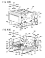
- Fig. 1(A) is a perspective view of a laser printer in which a door is closed as viewed from an upper right front side of the printer according to one embodiment of the present invention
- Fig. 1 (B) is a perspective view of the laser printer in which the door is closed as viewed from a lower left rear side of the printer according to the embodiment;
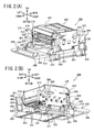
- Fig. 2 (A) is a perspective view of the laser printer in which the door is open, as viewed from the upper right front side of the printer according to the embodiment;
- Fig. 2(B) is a perspective view of the laser printer in which the door is open as viewed from the lower left rear side of the printer according to the embodiment;
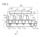
- Fig. 3 is a schematic view showing a structure of an image forming system in the laser printer according to the embodiment
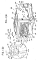
- Fig. 4(A) is a perspective view showing an internal structure of the laser printer according to the embodiment as viewed from a direction the same as that in Fig. 1(A) , but a part of the door is omitted for simplicity;
- Fig. 4(B) is an enlarged view of a portion A marked by a circle A of Fig. 4(A) ;
- Fig. 5(A) is a left side view showing a structure of the laser printer when the door is closed according to the embodiment
- Fig. 5(B) is an enlarged view of a portion B marked by a circle B of Fig. 5(A) ;
- Fig. 6(A) is a perspective view showing a structure of the laser printer when the door is open as viewed from the upper right front side of the printer according to the embodiment;
- Fig. 6(B) is an enlarged view of a portion C marked by a circle C of Fig. 6(A) ;
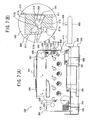
- Fig. 7(A) is a left side view showing a structure of the laser printer when the door is open according to the embodiment.
- Fig. 7(B) is an enlarged view of a portion D marked by a circle D of Fig. 7(A) .
- the laser printer 100 includes a main frame 200 and an image forming system 300.
- the main frame 200 is formed substantially in a box shape.
- An outer cover (not shown) formed of resin is formed over an outer surface of the main frame 200.
- the image forming system 300 includes an image forming unit 350 capable of being pulled out of the main frame 200 and detachably mounted on the main frame 200.
- the image forming system 300 includes a belt unit 310 (a conveyer unit), a scanner unit 330, a fixing unit 340, and an image forming unit 350 including four process units 320 and a drum sub unit 351 ( Figs. 2(A) and 2(B) ).
- the belt unit 310 includes a drive roller 311, a driven roller 312, and an endless conveying belt (transfer belt) 313 stretched around the drive roller 311 and the driven roller 312, and four transfer rollers 314.
- the process units 320 constitute a direct transfer tandem type color image forming system.
- the process units 320 are disposed above the belt unit 310, and juxtaposed in the front-to-rear direction in order of the colors black (K), yellow (Y), magenta (M), and cyan (C) from the front side of the laser printer 100.
- Each of the process units 320 is detachably stored in each of four storages (not shown) provided in the drum sub unit 351 constituting a frame of the image forming unit 350.
- Each of the process units 320 includes a photosensitive drum 321 (an image bearing member), a scorotron charger 322, and a developing cartridge 324, and a developing roller 326.
- the photosensitive drum 321 includes a grounded drum body formed of metal, and a positively chargeable photosensitive layer formed of polycarbonate formed on an outer surface of the drum body.
- the scorotron charger 322 is disposed diagonally above and rearward of the photosensitive drum 321 and opposes the photosensitive drum 321 at a prescribed distance so as not to contact the same.
- the scorotron charger 322 has a charging wire formed of tungsten to generate corona discharge so that the surface of the photosensitive drum 321 can be uniformly charged to have a positive polarity.
- Each of the developing cartridges 324 defines therein a toner chamber 325 in which a positively chargeable, nonmagnetic, single-component toner in one of the colors black, cyan, magenta and yellow as a developing agent is retained.
- the developing roller 326 is provided between the photosensitive drum 321 and the toner chamber 325 for supplying toner positively tribocharged to the photosensitive drum 321.
- the transfer rollers 314 are respectively disposed opposite to the photosensitive drums 321.
- the conveying belt 313 is pinched between the transfer rollers 314 and the photosensitive drums 321.
- the conveying belt 313 moves circularly in a clockwise direction the same as the direction that the drive roller 311 rotates.
- a sheet supply tray (not shown) is provided in a lower section of the main frame 200.
- a sheet P as a recording medium is supplied to a surface of the conveying belt 313 by a supply roller (not shown) from the sheet supply tray.
- the sheet P on the conveying belt 313 moves past the photosensitive drums 321 and is conveyed to the rear side of the laser printer 100.
- the scanner unit 330 is disposed above the process units 320.
- the scanner unit 330 includes a semiconductor laser (not shown) adapted for generating laser beams Lk, Ly, Lm, and Lc corresponding to image data of each color, and a polygon mirror (not shown) deflecting a laser beam L for scanning over the photosensitive drums 321 and exposes the same to the laser beam.
- the surface of each photosensitive drum 321 is uniformly charged to have a positive polarity by the scoroton charger 322 when rotating. Then, the surface is subjected to high speed scan of the laser beam L, so that an electrostatic latent image corresponding to an image to be formed on the sheet P is formed on the surface.
- the toner images formed on the surfaces of the photosensitive drums 321 are sequentially transferred onto the sheet P by a transfer bias with a negative polarity applied to the transfer rollers 314 by a constant current control, each time the sheet P conveyed on the conveying bet 313 passes between each photosensitive drum 321 and each transfer roller 314.
- the sheet P bearing the toner image is then conveyed to the fixing unit 340 disposed rearward of the belt unit 310.
- the fixing unit 340 includes a heat roller 341 and a pressure roller 342.
- the heat roller 341 is drivingly rotatable and includes a heat source such as a halogen lamp.
- the pressure roller 342 is disposed below the heat roller 341 and opposes the heat roller 341 to press the same.
- the pressure roller 342 rotates in association with rotation of the heat roller 341.
- the sheet P on which the toner image with the four colors is formed is heated while conveyed between the heat roller 341 and the pressure roller 342, so that the toner image is thermally fixed on the sheet P.
- the sheet P on which the toner image has been fixed is conveyed by several rollers (not shown) and discharged to a discharge tray (not shown) provided in a top surface of the laser printer 100.
- the drum sub unit 351 constitutes the image forming unit 350, and is adapted to retain four process units 320.
- the drum sub unit 351 retaining the four process units 320 is detachably installable to the main frame 200 as a detachable image forming unit 350.
- the drum sub unit 351 has a front side provided with a support shaft 352 extending along a front frame section of the drum sub unit 351 in a right-to-left direction (lateral direction). Each end of the support shaft 352 laterally outwardly protrudes from right and left side frame sections of the drum sub unit 351.
- the support shaft 352 functions as a second positioning part.
- the right and left side frame sections of the drum sub unit 351 has rear end portions formed with cutout parts 353.
- Each cutout part 353 is open at a rear end face of each side frame section, and extends frontward.
- the main frame 200 includes a pair of metal frames 210, and a pair of resin frames 250 positioned immediately below the pair of metal frames 210 for supporting the same.
- the pair of metal frames 210 is adapted for supporting the scanner unit 330 and the image forming unit 350.
- the scanner unit 330 has a scanner plate (not shown) fixed by screws on an upper portion of the metal frames 210. Thus, the scanner unit 330 can be supported horizontally in the upper portion of the metal frames 210.
- Each lower edge of the metal frames 210 is in contact with each upper edge of the resin frames 250.
- Each of the resin frames 250 has a laterally outward portion protruding laterally outward of the metal frames 210, and the laterally outward portion is fixed to the metal frames 210 by screws 251.
- a front beam 252 is fixed by screws to bottom surfaces of the resin frames 250 at a front side thereof.
- a rear beam 253 is fixed by screws to the bottom surfaces of the resin frames 250 at a rear side thereof.
- the resin frames 250 are connected each other by the front beam 252 and the rear beam 253.
- Each side frame section of the main frame 200 has a front end formed with a hole 211 allowing the support shaft 352 to extend therethrough.
- each end of the support shaft 352 is brought into engagement with each hole 211.
- each front portion of each side frame section is bent laterally outward so as to form a flange 212, and the hole 211 is formed in the flange 212 to form an L-shape. That is, the hole 211 has a front opening and extends rearward.
- the hole 211 defines a lower surface 211a extending horizontally and rearward.
- Each end portion of the support shaft 352 is placed on the lower surfaces 211a so that the front end of the image forming unit 350 is subjected to positioning in a vertical direction.
- the lower surface 211a functions as a first positioning part or as an end face.
- the hole 211 also defines an upper slant surface 211b (a second shift portion) extending diagonally rearward and downward, and a rear surface 211c extending vertically.
- a reference shaft 220 bridges between the pair of metal frames 210 at a rear portion thereof, so that the cutout parts 353 is engageable with the reference shaft 220 when the image forming unit 350 is mounted on the main frame 200.
- the engagement defines the position of the rear end of the image forming unit 350 in the vertical direction and in the front-to-rear direction.
- each metal frame 210 is formed with a square hole 213 at a rear portion thereof, and each end portion of the reference shaft 220 extends through the square hole 213.
- Each end portion of the reference shaft 220 is urged by a linear spring 230 towards a lower rear corner of the square hole 213 for positioning.
- the holes 211 and the square holes 213 are concurrently formed on the metal frames 210 by a press forming together with screw holes (not shown) for fixing the scanner unit 330. Further, portions of the metal frame 210 around the screw holes, the holes 211, and the square holes 213 are not bent but flat. Therefore, enhanced positional accuracy between the scanner unit 330 and the image forming unit 350 can result in the laser printer 100, and eventually, positional accuracy between the scanner unit 330 and each of the photosensitive drums 321 can be improved. Accordingly, an accurate image can be formed.
- the drum sub unit 351 is guided by a guide (not shown) so that the reference shaft 220 can fit with the cutout parts 353 for assembly of the image forming unit 350 into the main frame 200.
- a guide structure is disclosed in laid open Japanese patent application publication No. 2007-121983 . Accordingly, a detailed explanation will be omitted.
- each metal frame 210 is orthogonally bent outward.
- a scanner cover 241 formed of metal and covering an upper front half portion of the scanner unit 330 is fixed to the upper end portion by screws.
- the belt unit 310 described above is detachably mounted between the pair of resin frames 250.
- a door 400 is pivotably movable between a vertical closed position for closing a front space defined between the pair of metal frames 210 and a horizontal open position for exposing the image forming unit 350 to an atmosphere through the pair of metal frames 210.
- the resin frame 250 has an upper front portion provided with a pivot shaft 255 protruding laterally outwardly.
- a generally sector-shaped eccentric cam plate 410 is attached to each pivot shaft 255 and pivotally movable about an axis thereof.
- the cam plate 410 has an arcuate cam surface, and has a configuration such that a radius between the arcuate cam surface and the axis of the pivot shaft 255 is gradually reduced toward the door 400.
- the door 400 is integrally with each of the cam plates 410 at a radially shortest end thereof.
- Each of the cam plates 410 is positioned rearward of the door 400 (a side of the main frame 200) when the door 400 is at its closed position.
- the door 400 has a hook 420 protruding from an inner surface thereof (a rear side of the door 400 when the door 400 is at its closed position).
- each flange 212 is formed with upper and lower vertically elongated slots 214 vertically aligned with each other. Each lower end portion of each slot 214 has a width greater than that of the remaining portion thereof.
- a lock member 500 is vertically slidably movably supported to the each flange 212. That is, each lock member 500 is positioned on a rear surface of each flange 212.
- the lock member 500 includes engagement portions 501 engaged with the slots 214, so that the lock member 500 is vertically slidable on the rear surface of the flange 212.
- the engagement portions 501 have an enlarged head positioned in front of each flange 212.
- the lock member 500 is made of a resin, so that its hardness is lower than that of the metal frame 210 and the support shaft 352 those made from a metal.
- a lower end of the lock member 500 is formed with a chamfered portion 502 for providing a smooth contact with the arcuate cam surface of the cam plate 410, so that the lock member 500 can move upward and downward in association with the movement of the door 400.
- the lock member 500 descends when the door 400 is at its closed position as shown in Fig. 1 (A) , since the chamfered portion 502 is in contact with the smaller radius portion of the cam surface.
- the lock member 500 ascends when the door 400 is at its open position as shown in Fig. 2(A) , since the chamfered portion 502 is in contact with the greater radius portion of the cam surface.
- each of the lock member 500 has a recessed portion 510 at a portion superposed with the hole 211.
- the recessed portion 510 has a front opening and is cutout in an inner side of the lock member 500.
- an outer surface of the lock member 500 is partially omitted for simplicity in order to clarify the shape of the recessed portion 510.
- the recessed portion 510 defines a lower surface and an upper surface extending rearward.
- the lower surface has a first inclined surface 511, a horizontal flat surface 512, and a protruding part 513.
- the first inclined surface 511 inclines upward toward a bottom end of the recessed portion 510.
- the horizontal flat surface 512 functioning as a shift portion or as a restraining portion, is connected from a rear end of the first inclined surface 511.
- the protruding part 513 protrudes upward from the rear end of the horizontal flat surface 512 and is generally rectangular-shaped.
- the protruding part 513 has a vertical surface 513a connected to the horizontal flat surface 512, and an upper surface 513b connected to the vertical surface 513a. A rear end of the upper surface 513b is connected to a bottom surface of the recessed portion 510.
- the upper surface has a second inclined surface 516 and a third inclined surface 517.
- the second inclined surface 516 slightly inclines downward toward the bottom of the recessed portion 510.
- the third inclined surface 517 functioning as a pressure portion, is connected to the rear end of the second inclined surface 516 and inclines upward toward the bottom of the recessed portion 510. Angle between the second and third inclined surfaces 516 and 517 is approximately 135 degrees.
- each lock member 500 has a locking hook 520 which is integrally formed with the lock member 500.
- the locking hook 520 is engaged with the hook 420 of the door 400 when the door 400 is at its closed position. This engagement can maintain the closing state of the door 400.
- the flange 212 is formed with a hole 215 allowing the hook 420 to extend therethrough as shown in Fig. 6(A) . Thus, the hook 420 is engagable with the locking hook 520.
- the locking hook 520 is formed of resin and is integrally with a main body 540 of the lock member 500 via a U-shaped leaf spring plate 521.
- a coil spring 530 is interposed between an upper surface of the main body 540 and the locking hook 520.
- a first regulation hook 543 protrudes upward from the upper surface of the main body 540, and a second regulation hook 523 protrudes downward from a lower portion of the locking hook 520.
- the first regulation hook 543 is engageable with the second regulation hook 523 so that excessive urging of the locking hook 520 toward the hook 420 by the biasing force of the coil spring 530 can be restrained.
- a combination of the main body 540, the U-shaped leaf spring plate 521, the hooks 520, 523, 543 and the coil spring 530 is referred to as a lock unit.
- Figs. 7 (A) and 7(B) the outer surface of the lock member 500 is partially omitted, in the same manner as Figs. 5(A) and 5(B) .
- Figs. 6(B) and 7(B) when the door 400 is at its open position and the lock member 500 moves upward, the first inclined surface 511 and the horizontal flat surface 512 of the recessed portion 510 is moved to a position above the lower surface 211a of the hole 211.
- the upper surface, 513b of the protruding part 513 is positioned above a lower part of the upper slant surface 211b of the hole 211, and the first inclined surface 511 is positioned below the upper slant surface 211b and above the lower surface 211a.
- the support shaft 352 When the door 400 is at its open position for detachment or attachment of the image forming unit 350 relative to the main frame 200, the support shaft 352 is not in direct contact with the lower surface 211a because the first inclined surface 511 and the horizontal flat surface 512 are disposed above the lower surface 211a, even if the image forming unit 350 is slammingly pushed into the main frame 200. Further, since the upper surface 513b of the protruding part 513 is disposed above the lower portion of the upper slant surface 211b, the support shaft 352 can be brought into contact with a lower portion of the vertical surface 513a of the protruding part 513, i.e., base end portion thereof.
- the image forming unit 350 can be restrained from being excessively inserted into rearward. It should be noted that the cutout parts 353 are not fully engaged with the reference shaft 220 when the support shaft 352 is in contact with the base end portion of the protruding part 513. Hence, the reference shaft 220 can be restrained from being in impacting contact with the cutout parts 353 at an initial insertion phase of the image forming unit 350 into the main frame 200.
- the third inclined surface 517 is positioned above the support shaft 352 if the support shaft 352 is placed on the horizontal flat surface 512.
- the lock member 500 is moved downward and the hook 420 extends into the hole 215 and is brought into engagement with the locking hook 520.
- the third inclined surface 517 presses the support shaft 352 downward and rearward as shown in Fig. 5(B) because of the biasing force transmitted from the hook 420, the U-shaped leaf spring plate 521, the locking hook 520, and the coil spring 530.
- the first inclined surface 511, the horizontal flat surface 512, and the protruding part 513 are positioned below the lower surface 211a.
- the support shaft 352 is in direct contact with the lower surface 211a of the hole 211, and the image forming unit 350 as a whole can further be pressed rearward.
- the cutout parts 353 can be engaged with the reference shaft 220.
- the image forming unit 350 is positioned at a prescribed location in the main frame 200 so that an accurate image can be formed on the sheet P.
- the lower surface 211a is moved to a position below the upper surface 513b, so that the support shaft 352 will be transferred from the lower surface 211a to the upper surface 513b.
- the support shaft 352 is rolled down onto the horizontal flat surface 512 from the upper surface 513b of the protruding part 513 because of the urging force from the upper slant surface 211b. Since the lock member 500 is moved upward, the support shaft 352 on the horizontal flat surface 512 is lifted above the lower surface 211a of the hole 211.
- the image forming unit 350 is moved frontward by a length of the upper surface 513b, and is moved upward by a vertical distance between the lower surface 211a and the horizontal flat surface 512 as shown in Fig. 7(B) .
- This frontward and upward movement facilitates removal of the image forming unit 350.
- the photosensitive drums 321 are moved away from the conveying belt 313.
- a guide mechanism described in laid open Japanese patent application publication No. 2007-121983 can be provided in the laser printer 100 for positively moving the image forming unit 350 upward when the image forming unit 350 is being pulled out frontward. In the latter case, the photosensitive drums 321 can surely be moved away from the conveying belt 313.
- the third inclined surface 517 is provided in the lock member 500 formed integrally with the locking hook 520 for maintaining the door 400 in a closed state.
- the structure of the laser printer 100 can be simplified by reducing the number of parts and components, and eventually, cost reduction for manufacturing the laser printer 100 can be attained.
- engagement between the support shaft 352 and the lower surface 211a of the hole 211 formed on the metal frame 210 can provide positioning of the image forming unit 350. Further, the support shaft 352 is directly pressed by the third inclined surface 517. The image forming unit 350 can be subjected to proper positioning relative to the main frame 200. Accordingly, the laser printer 100 in the present embodiment is capable of forming an accurate image on the sheet P.
- the protruding part 513 and the horizontal flat surface 512 integrally formed in the lock member 500 facilitates separation of the photosensitive drums 321 from the conveying belt 313 when the door 400 is at its open position.
- the photosensitive drums 321 can be protected against any scratch or injury because no frictional contact with the conveyer belt 313 during detachment work of the image forming unit 350.
- the first inclined surface 511 and the horizontal flat surface 512 are positioned above the lower surface 211a of the hole 211 when the door 400 is open. Therefore, direct abutment of the support shaft 352 onto the lower surface 211a can be restrained. Accordingly, frictional wearing of the lower surface 211a and the support shaft 352 can be avoided to enable stabilized image forming operation for a prolonged period.
- the first inclined surface 511, the horizontal flat surface 512 and the protruding part 513 are retracted to a position lower than the lower surface 211a when the door 400 is closed.
- abutment between the support shaft 352 and the lower surface 211a can be provided, so that the image forming unit 350 can be subjected to positioning at a given position within the frame 200.
- the support shaft 352 is pressed by the third inclined surface 517, stabilized positioning can be made. Accordingly, performance of image forming operation can be further ensured.
- the first inclined surface 511, the horizontal flat surface 512 and the protruding part 513 those preventing the support shaft 352 from directly abutting on the lower surface 211a are provided integrally with the locking member 500 having the locking hook 520 that maintains the door 400 in its closed position. Accordingly, a simplified construction can be provided eliminating mechanical parts and components, thereby lowering production cost. Further, positioning of the image forming unit 350 is attained by the engagement between the support shaft 352 and the lower surface 211a of the hole 211 formed in the metal frame 200 and, the third inclined surface 517 directly presses the support shaft 352. Accordingly, sufficient positioning of the image forming unit 350 relative to the frame 200 is achievable. Thus, the resultant laser printer 100 can produce accurate visible image on the sheet P.
- the present invention can be applied to several types of an image forming device, such as, a monochromatic laser printer, a facsimile machine, an ink jet printer, and a copying machine.
- the image forming unit 350 is detachable from the main frame 200.
- the present invention is not only available for the image forming unit of complete detachment type but also for an image forming unit of non-detachable type. In the latter case, the image forming unit can be pulled out and inserted into the main frame without any detachment from the main frame.
- the image forming unit 350 can be pulled out of the main frame 200 to the extent that each of the developing cartridges 324 is exchangeable.
- the developing cartridges 324 and the photosensitive drums 321 are assembled in a single process cartridge unit.
- a cartridge including only the developing cartridge is also available in the present invention.
- the pressure portion (the third inclined surface 517) can press any part of the image forming unit other than the support shaft 352.
- direct pressure applied by the third inclined surface 517 against the support shaft 352 can provide accurate positioning of the image forming unit 350 with respect to the main frame 200.
- the lock member 500 is engaged with the support shaft 352 for positioning the image forming unit 350.
- the lock member 500 can be engaged with a part or component of the image forming unit 350 other than the support shaft 352. Still however, as long as the locking member 500 made from a resin is provided where the engagement surface of the locking member 500 is moved upward exceeding the lower surface 211a in response to the opening stroke of the door 400 in order to protect the lower surface 211a, the support shaft 352 would be a desirable component to be brought into abutment with the engagement surface.
- frictional wearing of the support shaft 352 can be efficiently reduced because the locking member 500 is made from the resin. Consequently, frictional abrasion of the lower surface 211a and the support shaft 352 can further be reduced to provide desirable image forming operation for a prolonged period of time.
- the above-described embodiment pertains to the direct transfer tandem type color image forming system where the sheet P is conveyed by the conveying belt 313 so as to sequentially pass through the photosensitive drums 321 for directly receiving toner images from the photosensitive drums 321 onto the sheet P.
- the present invention is also available for an intermediate transfer tandem type color image forming system where the toner images formed on the photosensitive drums 321 are transferred onto an intermediate transfer belt, and then, the toner images transferred onto the intermediate transfer belt are transferred onto the sheet P.
Landscapes
- Physics & Mathematics (AREA)
- General Physics & Mathematics (AREA)
- Engineering & Computer Science (AREA)
- Computer Vision & Pattern Recognition (AREA)
- Electrophotography Configuration And Component (AREA)
Abstract

Description
- This application claims priority from Japanese Patent Application No.
2008-160741 filed June 19, 2008 - The present invention relates to an image forming device having an image forming system for forming an image on a recording medium. More specifically, the present invention relates to an image forming device having an image forming unit detachably supported by a frame, the image forming unit being a major part of the image forming system.
- In a conventional image forming device, it is proposed that an image forming system is supported to a frame, and an image forming unit which is a part of the image forming system is detachably mounted on the frame. For example, with regard to a color laser printer having four developing cartridges corresponding to each color of black, yellow, magenta, and cyan, proposal has been made that developing cartridges and photosensitive drums are detachably mounted on a frame as an integral image forming unit. In this case, improved maintenance efficiency can be obtained because four developing cartridges can be integrally removed from a frame.
- Japanese laid open patent application publication No.
8-220824 - However, in the image forming device described above, the image forming unit may be displaced from the prescribed location when the door is open. Accordingly, a lock mechanism is required for maintaining the door in a closed state during image forming operation. However, as described above, the number of parts and components to provide such mechanism increases and configuration of the device becomes more complex if a mechanism for positioning an image forming unit and the above lock mechanism are provided in association with the door.
- It is therefore an object of the present invention to provide an image forming device having a simple construction capable of facilitating positioning of an image forming unit supported by a frame and detachable from the frame when a door is open, and capable of maintaining a closed state of the door after the image forming unit is inserted into the frame.
- This and other objects of the present invention will be attained by providing an image forming device including a frame, an image forming unit, a door, a lock unit, and a pressure portion. The frame has a first positioning part. The image forming unit is detachably supported to the frame and has a second positioning part abuttable on the first positioning part for positioning the image forming unit relative to the frame. The door is movable between an open position and a closed position relative to the frame. The image forming unit is detachable from or attachable to the frame at the open position. The lock unit is lockingly engageable with the door at the closed position of the door for maintaining the closed position. The pressure portion is provided at the lock unit and is configured to urge the image forming unit so as to press the second positioning part onto the first positioning part at the closed position of the door.
- In the drawings;
-
Fig. 1(A) is a perspective view of a laser printer in which a door is closed as viewed from an upper right front side of the printer according to one embodiment of the present invention; -
Fig. 1 (B) is a perspective view of the laser printer in which the door is closed as viewed from a lower left rear side of the printer according to the embodiment; -
Fig. 2 (A) is a perspective view of the laser printer in which the door is open, as viewed from the upper right front side of the printer according to the embodiment; -
Fig. 2(B) is a perspective view of the laser printer in which the door is open as viewed from the lower left rear side of the printer according to the embodiment; -
Fig. 3 is a schematic view showing a structure of an image forming system in the laser printer according to the embodiment; -
Fig. 4(A) is a perspective view showing an internal structure of the laser printer according to the embodiment as viewed from a direction the same as that inFig. 1(A) , but a part of the door is omitted for simplicity; -
Fig. 4(B) is an enlarged view of a portion A marked by a circle A ofFig. 4(A) ; -
Fig. 5(A) is a left side view showing a structure of the laser printer when the door is closed according to the embodiment; -
Fig. 5(B) is an enlarged view of a portion B marked by a circle B ofFig. 5(A) ; -
Fig. 6(A) is a perspective view showing a structure of the laser printer when the door is open as viewed from the upper right front side of the printer according to the embodiment; -
Fig. 6(B) is an enlarged view of a portion C marked by a circle C ofFig. 6(A) ; -
Fig. 7(A) is a left side view showing a structure of the laser printer when the door is open according to the embodiment; and -
Fig. 7(B) is an enlarged view of a portion D marked by a circle D ofFig. 7(A) . - Next, a laser printer as an image forming device according to one embodiment of the present invention will be described with reference to
Figs. 1(A) to 7(B) . Thelaser printer 100 includes amain frame 200 and animage forming system 300. Themain frame 200 is formed substantially in a box shape. An outer cover (not shown) formed of resin is formed over an outer surface of themain frame 200. Theimage forming system 300 includes animage forming unit 350 capable of being pulled out of themain frame 200 and detachably mounted on themain frame 200. - The
image forming system 300 includes a belt unit 310 (a conveyer unit), ascanner unit 330, afixing unit 340, and animage forming unit 350 including fourprocess units 320 and a drum sub unit 351 (Figs. 2(A) and 2(B) ). Thebelt unit 310 includes adrive roller 311, a drivenroller 312, and an endless conveying belt (transfer belt) 313 stretched around thedrive roller 311 and the drivenroller 312, and fourtransfer rollers 314. Theprocess units 320 constitute a direct transfer tandem type color image forming system. Theprocess units 320 are disposed above thebelt unit 310, and juxtaposed in the front-to-rear direction in order of the colors black (K), yellow (Y), magenta (M), and cyan (C) from the front side of thelaser printer 100. Each of theprocess units 320 is detachably stored in each of four storages (not shown) provided in thedrum sub unit 351 constituting a frame of theimage forming unit 350. - Each of the
process units 320 includes a photosensitive drum 321 (an image bearing member), ascorotron charger 322, and a developingcartridge 324, and a developingroller 326. Thephotosensitive drum 321 includes a grounded drum body formed of metal, and a positively chargeable photosensitive layer formed of polycarbonate formed on an outer surface of the drum body. - The
scorotron charger 322 is disposed diagonally above and rearward of thephotosensitive drum 321 and opposes thephotosensitive drum 321 at a prescribed distance so as not to contact the same. Thescorotron charger 322 has a charging wire formed of tungsten to generate corona discharge so that the surface of thephotosensitive drum 321 can be uniformly charged to have a positive polarity. - Each of the developing
cartridges 324 defines therein atoner chamber 325 in which a positively chargeable, nonmagnetic, single-component toner in one of the colors black, cyan, magenta and yellow as a developing agent is retained. The developingroller 326 is provided between thephotosensitive drum 321 and thetoner chamber 325 for supplying toner positively tribocharged to thephotosensitive drum 321. - The
transfer rollers 314 are respectively disposed opposite to thephotosensitive drums 321. Theconveying belt 313 is pinched between thetransfer rollers 314 and thephotosensitive drums 321. Theconveying belt 313 moves circularly in a clockwise direction the same as the direction that thedrive roller 311 rotates. A sheet supply tray (not shown) is provided in a lower section of themain frame 200. A sheet P as a recording medium is supplied to a surface of theconveying belt 313 by a supply roller (not shown) from the sheet supply tray. The sheet P on theconveying belt 313 moves past thephotosensitive drums 321 and is conveyed to the rear side of thelaser printer 100. - The
scanner unit 330 is disposed above theprocess units 320. Thescanner unit 330 includes a semiconductor laser (not shown) adapted for generating laser beams Lk, Ly, Lm, and Lc corresponding to image data of each color, and a polygon mirror (not shown) deflecting a laser beam L for scanning over thephotosensitive drums 321 and exposes the same to the laser beam. The surface of eachphotosensitive drum 321 is uniformly charged to have a positive polarity by thescoroton charger 322 when rotating. Then, the surface is subjected to high speed scan of the laser beam L, so that an electrostatic latent image corresponding to an image to be formed on the sheet P is formed on the surface. Subsequently, rotation of the developingroller 326 allows the positively charged toner retained in thetoner chamber 325 to be supplied to thephotosensitive drum 321. Therefore, a visible toner image corresponding to the electrostatic latent image can be formed on the surface of thephotosensitive drum 321. In other words, toner is deposited only at the beam-irradiated regions of the surface of thephotosensitive drum 321. - The toner images formed on the surfaces of the
photosensitive drums 321 are sequentially transferred onto the sheet P by a transfer bias with a negative polarity applied to thetransfer rollers 314 by a constant current control, each time the sheet P conveyed on the conveyingbet 313 passes between eachphotosensitive drum 321 and eachtransfer roller 314. The sheet P bearing the toner image is then conveyed to the fixingunit 340 disposed rearward of thebelt unit 310. - The fixing
unit 340 includes aheat roller 341 and apressure roller 342. Theheat roller 341 is drivingly rotatable and includes a heat source such as a halogen lamp. Thepressure roller 342 is disposed below theheat roller 341 and opposes theheat roller 341 to press the same. Thepressure roller 342 rotates in association with rotation of theheat roller 341. In the fixingunit 340, the sheet P on which the toner image with the four colors is formed is heated while conveyed between theheat roller 341 and thepressure roller 342, so that the toner image is thermally fixed on the sheet P. The sheet P on which the toner image has been fixed is conveyed by several rollers (not shown) and discharged to a discharge tray (not shown) provided in a top surface of thelaser printer 100. - As described above, the
drum sub unit 351 constitutes theimage forming unit 350, and is adapted to retain fourprocess units 320. Thedrum sub unit 351 retaining the fourprocess units 320 is detachably installable to themain frame 200 as a detachableimage forming unit 350. - As shown in
Fig. 4(A) , thedrum sub unit 351 has a front side provided with asupport shaft 352 extending along a front frame section of thedrum sub unit 351 in a right-to-left direction (lateral direction). Each end of thesupport shaft 352 laterally outwardly protrudes from right and left side frame sections of thedrum sub unit 351. Thesupport shaft 352 functions as a second positioning part. - As shown in
Figs. 1(B) and2(B) , the right and left side frame sections of thedrum sub unit 351 has rear end portions formed withcutout parts 353. Eachcutout part 353 is open at a rear end face of each side frame section, and extends frontward. - Incidentally, with regard to some parts of the
laser printer 100 described later, either one of the left side or the right side may be shown in the drawings. However, it should be understood that most parts of thelaser printer 100 are configured symmetrically. - Next, a structure of the
main frame 200 will be described. Themain frame 200 includes a pair ofmetal frames 210, and a pair of resin frames 250 positioned immediately below the pair ofmetal frames 210 for supporting the same. The pair of metal frames 210 is adapted for supporting thescanner unit 330 and theimage forming unit 350. Thescanner unit 330 has a scanner plate (not shown) fixed by screws on an upper portion of the metal frames 210. Thus, thescanner unit 330 can be supported horizontally in the upper portion of the metal frames 210. - Each lower edge of the metal frames 210 is in contact with each upper edge of the resin frames 250. Each of the resin frames 250 has a laterally outward portion protruding laterally outward of the metal frames 210, and the laterally outward portion is fixed to the metal frames 210 by
screws 251. Afront beam 252 is fixed by screws to bottom surfaces of the resin frames 250 at a front side thereof. Arear beam 253 is fixed by screws to the bottom surfaces of the resin frames 250 at a rear side thereof. The resin frames 250 are connected each other by thefront beam 252 and therear beam 253. - Each side frame section of the
main frame 200 has a front end formed with ahole 211 allowing thesupport shaft 352 to extend therethrough. When theimage forming unit 350 is mounted on themain frame 200, each end of thesupport shaft 352 is brought into engagement with eachhole 211. More specifically, each front portion of each side frame section is bent laterally outward so as to form aflange 212, and thehole 211 is formed in theflange 212 to form an L-shape. That is, thehole 211 has a front opening and extends rearward. Thehole 211 defines alower surface 211a extending horizontally and rearward. Each end portion of thesupport shaft 352 is placed on thelower surfaces 211a so that the front end of theimage forming unit 350 is subjected to positioning in a vertical direction. Thelower surface 211a functions as a first positioning part or as an end face. Thehole 211 also defines anupper slant surface 211b (a second shift portion) extending diagonally rearward and downward, and arear surface 211c extending vertically. - A
reference shaft 220 bridges between the pair ofmetal frames 210 at a rear portion thereof, so that thecutout parts 353 is engageable with thereference shaft 220 when theimage forming unit 350 is mounted on themain frame 200. Thus, the engagement defines the position of the rear end of theimage forming unit 350 in the vertical direction and in the front-to-rear direction. More specifically, eachmetal frame 210 is formed with asquare hole 213 at a rear portion thereof, and each end portion of thereference shaft 220 extends through thesquare hole 213. Each end portion of thereference shaft 220 is urged by alinear spring 230 towards a lower rear corner of thesquare hole 213 for positioning. - The
holes 211 and thesquare holes 213 are concurrently formed on the metal frames 210 by a press forming together with screw holes (not shown) for fixing thescanner unit 330. Further, portions of themetal frame 210 around the screw holes, theholes 211, and thesquare holes 213 are not bent but flat. Therefore, enhanced positional accuracy between thescanner unit 330 and theimage forming unit 350 can result in thelaser printer 100, and eventually, positional accuracy between thescanner unit 330 and each of thephotosensitive drums 321 can be improved. Accordingly, an accurate image can be formed. - Incidentally, the
drum sub unit 351 is guided by a guide (not shown) so that thereference shaft 220 can fit with thecutout parts 353 for assembly of theimage forming unit 350 into themain frame 200. Such a guide structure is disclosed in laid open Japanese patent application publication No.2007-121983 - Further, an upper end portion of each
metal frame 210 is orthogonally bent outward. Ascanner cover 241 formed of metal and covering an upper front half portion of thescanner unit 330 is fixed to the upper end portion by screws. Thebelt unit 310 described above is detachably mounted between the pair of resin frames 250. - A
door 400 is pivotably movable between a vertical closed position for closing a front space defined between the pair ofmetal frames 210 and a horizontal open position for exposing theimage forming unit 350 to an atmosphere through the pair of metal frames 210. More specifically, theresin frame 250 has an upper front portion provided with apivot shaft 255 protruding laterally outwardly. A generally sector-shapedeccentric cam plate 410 is attached to eachpivot shaft 255 and pivotally movable about an axis thereof. Thecam plate 410 has an arcuate cam surface, and has a configuration such that a radius between the arcuate cam surface and the axis of thepivot shaft 255 is gradually reduced toward thedoor 400. Thedoor 400 is integrally with each of thecam plates 410 at a radially shortest end thereof. Each of thecam plates 410 is positioned rearward of the door 400 (a side of the main frame 200) when thedoor 400 is at its closed position. Thedoor 400 has ahook 420 protruding from an inner surface thereof (a rear side of thedoor 400 when thedoor 400 is at its closed position). - As shown in
Fig. 4(A) , eachflange 212 is formed with upper and lower verticallyelongated slots 214 vertically aligned with each other. Each lower end portion of eachslot 214 has a width greater than that of the remaining portion thereof. Alock member 500 is vertically slidably movably supported to the eachflange 212. That is, eachlock member 500 is positioned on a rear surface of eachflange 212. Thelock member 500 includesengagement portions 501 engaged with theslots 214, so that thelock member 500 is vertically slidable on the rear surface of theflange 212. Theengagement portions 501 have an enlarged head positioned in front of eachflange 212. For assembly of thelock member 500 to theflange 212, the head can be inserted through the greater width portion of eachslot 214. Thelock member 500 is made of a resin, so that its hardness is lower than that of themetal frame 210 and thesupport shaft 352 those made from a metal. - As best shown in
Fig. 5(A) , a lower end of thelock member 500 is formed with a chamferedportion 502 for providing a smooth contact with the arcuate cam surface of thecam plate 410, so that thelock member 500 can move upward and downward in association with the movement of thedoor 400. In other words, thelock member 500 descends when thedoor 400 is at its closed position as shown inFig. 1 (A) , since the chamferedportion 502 is in contact with the smaller radius portion of the cam surface. On the other hand, thelock member 500 ascends when thedoor 400 is at its open position as shown inFig. 2(A) , since the chamferedportion 502 is in contact with the greater radius portion of the cam surface. - As shown in
Fig. 5(B) , each of thelock member 500 has a recessedportion 510 at a portion superposed with thehole 211. The recessedportion 510 has a front opening and is cutout in an inner side of thelock member 500. InFigs. 5(A) and 5(B) , an outer surface of thelock member 500 is partially omitted for simplicity in order to clarify the shape of the recessedportion 510. - As shown in
Fig. 5(B) , the recessedportion 510 defines a lower surface and an upper surface extending rearward. As viewed from the front opening of the recessedportion 510, the lower surface has a firstinclined surface 511, a horizontalflat surface 512, and aprotruding part 513. The firstinclined surface 511 inclines upward toward a bottom end of the recessedportion 510. The horizontalflat surface 512, functioning as a shift portion or as a restraining portion, is connected from a rear end of the firstinclined surface 511. The protrudingpart 513 protrudes upward from the rear end of the horizontalflat surface 512 and is generally rectangular-shaped. That is, the protrudingpart 513 has avertical surface 513a connected to the horizontalflat surface 512, and anupper surface 513b connected to thevertical surface 513a. A rear end of theupper surface 513b is connected to a bottom surface of the recessedportion 510. - As viewed from the front opening of the recessed
portion 510, the upper surface has a secondinclined surface 516 and a thirdinclined surface 517. The secondinclined surface 516 slightly inclines downward toward the bottom of the recessedportion 510. The thirdinclined surface 517, functioning as a pressure portion, is connected to the rear end of the secondinclined surface 516 and inclines upward toward the bottom of the recessedportion 510. Angle between the second and thirdinclined surfaces - An upper portion of each
lock member 500 has alocking hook 520 which is integrally formed with thelock member 500. Thelocking hook 520 is engaged with thehook 420 of thedoor 400 when thedoor 400 is at its closed position. This engagement can maintain the closing state of thedoor 400. Theflange 212 is formed with ahole 215 allowing thehook 420 to extend therethrough as shown inFig. 6(A) . Thus, thehook 420 is engagable with thelocking hook 520. - As shown in
Fig. 5(A) , the lockinghook 520 is formed of resin and is integrally with amain body 540 of thelock member 500 via a U-shapedleaf spring plate 521. Acoil spring 530 is interposed between an upper surface of themain body 540 and thelocking hook 520. Afirst regulation hook 543 protrudes upward from the upper surface of themain body 540, and asecond regulation hook 523 protrudes downward from a lower portion of thelocking hook 520. Thefirst regulation hook 543 is engageable with thesecond regulation hook 523 so that excessive urging of thelocking hook 520 toward thehook 420 by the biasing force of thecoil spring 530 can be restrained. A combination of themain body 540, the U-shapedleaf spring plate 521, thehooks coil spring 530 is referred to as a lock unit. - In
Figs. 7 (A) and 7(B) , the outer surface of thelock member 500 is partially omitted, in the same manner asFigs. 5(A) and 5(B) . As shown inFigs. 6(B) and7(B) , when thedoor 400 is at its open position and thelock member 500 moves upward, the firstinclined surface 511 and the horizontalflat surface 512 of the recessedportion 510 is moved to a position above thelower surface 211a of thehole 211. Further, the upper surface, 513b of theprotruding part 513 is positioned above a lower part of theupper slant surface 211b of thehole 211, and the firstinclined surface 511 is positioned below theupper slant surface 211b and above thelower surface 211a. - When the
door 400 is at its open position for detachment or attachment of theimage forming unit 350 relative to themain frame 200, thesupport shaft 352 is not in direct contact with thelower surface 211a because the firstinclined surface 511 and the horizontalflat surface 512 are disposed above thelower surface 211a, even if theimage forming unit 350 is slammingly pushed into themain frame 200. Further, since theupper surface 513b of theprotruding part 513 is disposed above the lower portion of theupper slant surface 211b, thesupport shaft 352 can be brought into contact with a lower portion of thevertical surface 513a of theprotruding part 513, i.e., base end portion thereof. Therefore, theimage forming unit 350 can be restrained from being excessively inserted into rearward. It should be noted that thecutout parts 353 are not fully engaged with thereference shaft 220 when thesupport shaft 352 is in contact with the base end portion of theprotruding part 513. Hence, thereference shaft 220 can be restrained from being in impacting contact with thecutout parts 353 at an initial insertion phase of theimage forming unit 350 into themain frame 200. - The third
inclined surface 517 is positioned above thesupport shaft 352 if thesupport shaft 352 is placed on the horizontalflat surface 512. In this state, if thedoor 400 is moved to its closed position, thelock member 500 is moved downward and thehook 420 extends into thehole 215 and is brought into engagement with thelocking hook 520. Accordingly, the thirdinclined surface 517 presses thesupport shaft 352 downward and rearward as shown inFig. 5(B) because of the biasing force transmitted from thehook 420, the U-shapedleaf spring plate 521, the lockinghook 520, and thecoil spring 530. At this time, the firstinclined surface 511, the horizontalflat surface 512, and theprotruding part 513 are positioned below thelower surface 211a. Thus, thesupport shaft 352 is in direct contact with thelower surface 211a of thehole 211, and theimage forming unit 350 as a whole can further be pressed rearward. Thus, thecutout parts 353 can be engaged with thereference shaft 220. Accordingly, theimage forming unit 350 is positioned at a prescribed location in themain frame 200 so that an accurate image can be formed on the sheet P. - As shown in
Fig. 5(B) , when thedoor 400 is at its closed position, thesupport shaft 352 is not in contact with therear surface 211c of thehole 211. This is because the engagement of thecutout parts 353 with thereference shaft 220 prevents theimage forming unit 350 from moving rearward. Further, as shown inFig. 5(A) , when thedoor 400 is at its full closed position, the chamferedportion 502 of thelock member 500 is out of contact from thecam plate 410. With such structure, dimensional variation in thecam plate 410 due to production error does not affect the downward movement of thelock member 500. Thus, thesupport shaft 352 can be properly pressed by the thirdinclined surface 517 for positioning theimage forming unit 350. Further, since thecoil spring 530 is interposed between the lockinghook 520 and themain body 540 of thelock member 500, occurrence of creep of theleaf spring plate 521 does not constitute a failure to transmit the pressing force from thehook 420 to the thirdinclined surface 517. - When the
door 400 is moved to the open position as shown inFigs. 7(A) and 7(B) from the closed position shown inFig. 5(A) , thelower surface 211a is moved to a position below theupper surface 513b, so that thesupport shaft 352 will be transferred from thelower surface 211a to theupper surface 513b. In accordance with the further upward movement of thelock member 500, thesupport shaft 352 is rolled down onto the horizontalflat surface 512 from theupper surface 513b of theprotruding part 513 because of the urging force from theupper slant surface 211b. Since thelock member 500 is moved upward, thesupport shaft 352 on the horizontalflat surface 512 is lifted above thelower surface 211a of thehole 211. - As a result, the
image forming unit 350 is moved frontward by a length of theupper surface 513b, and is moved upward by a vertical distance between thelower surface 211a and the horizontalflat surface 512 as shown inFig. 7(B) . This frontward and upward movement facilitates removal of theimage forming unit 350. Since the front end of theimage forming unit 350 is lifted up, thephotosensitive drums 321 are moved away from the conveyingbelt 313. Incidentally, a guide mechanism described in laid open Japanese patent application publication No.2007-121983 laser printer 100 for positively moving theimage forming unit 350 upward when theimage forming unit 350 is being pulled out frontward. In the latter case, thephotosensitive drums 321 can surely be moved away from the conveyingbelt 313. - In the
laser printer 100 according to the above-described embodiment, the thirdinclined surface 517 is provided in thelock member 500 formed integrally with thelocking hook 520 for maintaining thedoor 400 in a closed state. The structure of thelaser printer 100 can be simplified by reducing the number of parts and components, and eventually, cost reduction for manufacturing thelaser printer 100 can be attained. - In the present embodiment, engagement between the
support shaft 352 and thelower surface 211a of thehole 211 formed on themetal frame 210 can provide positioning of theimage forming unit 350. Further, thesupport shaft 352 is directly pressed by the thirdinclined surface 517. Theimage forming unit 350 can be subjected to proper positioning relative to themain frame 200. Accordingly, thelaser printer 100 in the present embodiment is capable of forming an accurate image on the sheet P. - Further, in the
laser printer 100, the protrudingpart 513 and the horizontalflat surface 512 integrally formed in thelock member 500 facilitates separation of thephotosensitive drums 321 from the conveyingbelt 313 when thedoor 400 is at its open position. Hence, thephotosensitive drums 321 can be protected against any scratch or injury because no frictional contact with theconveyer belt 313 during detachment work of theimage forming unit 350. - In the
laser printer 100 according to the above-described embodiment, the firstinclined surface 511 and the horizontalflat surface 512 are positioned above thelower surface 211a of thehole 211 when thedoor 400 is open. Therefore, direct abutment of thesupport shaft 352 onto thelower surface 211a can be restrained. Accordingly, frictional wearing of thelower surface 211a and thesupport shaft 352 can be avoided to enable stabilized image forming operation for a prolonged period. On the other hand, the firstinclined surface 511, the horizontalflat surface 512 and theprotruding part 513 are retracted to a position lower than thelower surface 211a when thedoor 400 is closed. Therefore, abutment between thesupport shaft 352 and thelower surface 211a can be provided, so that theimage forming unit 350 can be subjected to positioning at a given position within theframe 200. In this case, since thesupport shaft 352 is pressed by the thirdinclined surface 517, stabilized positioning can be made. Accordingly, performance of image forming operation can be further ensured. - Further, the first
inclined surface 511, the horizontalflat surface 512 and theprotruding part 513 those preventing thesupport shaft 352 from directly abutting on thelower surface 211a are provided integrally with the lockingmember 500 having the lockinghook 520 that maintains thedoor 400 in its closed position. Accordingly, a simplified construction can be provided eliminating mechanical parts and components, thereby lowering production cost. Further, positioning of theimage forming unit 350 is attained by the engagement between thesupport shaft 352 and thelower surface 211a of thehole 211 formed in themetal frame 200 and, the thirdinclined surface 517 directly presses thesupport shaft 352. Accordingly, sufficient positioning of theimage forming unit 350 relative to theframe 200 is achievable. Thus, theresultant laser printer 100 can produce accurate visible image on the sheet P. - Further, various modifications are conceivable.
- For example, the present invention can be applied to several types of an image forming device, such as, a monochromatic laser printer, a facsimile machine, an ink jet printer, and a copying machine. Further, in the above described embodiment, the
image forming unit 350 is detachable from themain frame 200. However, the present invention is not only available for the image forming unit of complete detachment type but also for an image forming unit of non-detachable type. In the latter case, the image forming unit can be pulled out and inserted into the main frame without any detachment from the main frame. For example, theimage forming unit 350 can be pulled out of themain frame 200 to the extent that each of the developingcartridges 324 is exchangeable. - Further, in the
image forming unit 350 of the above-described embodiment, the developingcartridges 324 and thephotosensitive drums 321 are assembled in a single process cartridge unit. However, a cartridge including only the developing cartridge is also available in the present invention. - Further, the pressure portion (the third inclined surface 517) can press any part of the image forming unit other than the
support shaft 352. However, direct pressure applied by the thirdinclined surface 517 against thesupport shaft 352 can provide accurate positioning of theimage forming unit 350 with respect to themain frame 200. - Further, in the above-described embodiment, the
lock member 500 is engaged with thesupport shaft 352 for positioning theimage forming unit 350. However, thelock member 500 can be engaged with a part or component of theimage forming unit 350 other than thesupport shaft 352. Still however, as long as the lockingmember 500 made from a resin is provided where the engagement surface of the lockingmember 500 is moved upward exceeding thelower surface 211a in response to the opening stroke of thedoor 400 in order to protect thelower surface 211a, thesupport shaft 352 would be a desirable component to be brought into abutment with the engagement surface. - Moreover, frictional wearing of the
support shaft 352 can be efficiently reduced because the lockingmember 500 is made from the resin. Consequently, frictional abrasion of thelower surface 211a and thesupport shaft 352 can further be reduced to provide desirable image forming operation for a prolonged period of time. - Further, the above-described embodiment pertains to the direct transfer tandem type color image forming system where the sheet P is conveyed by the conveying
belt 313 so as to sequentially pass through thephotosensitive drums 321 for directly receiving toner images from thephotosensitive drums 321 onto the sheet P. However, the present invention is also available for an intermediate transfer tandem type color image forming system where the toner images formed on thephotosensitive drums 321 are transferred onto an intermediate transfer belt, and then, the toner images transferred onto the intermediate transfer belt are transferred onto the sheet P. - While the invention has been described in detail and with reference to specific embodiment thereof, it would be apparent to those skilled in the art that various changes and modifications can be made within the scope and spirit of the invention.
Claims (12)
- An image forming device comprising:a frame having a first positioning part;an image forming unit detachably supported to the frame and having a second positioning part abuttable on the first positioning part for positioning the image forming unit relative to the frame;a door movable between an open position and a closed position relative to the frame, the image forming unit being detachable from or attachable to the frame at the open position; and,a lock unit lockingly engageable with the door at the closed position of the door for maintaining the closed position; anda pressure portion provided at the lock unit and configured to urge the image forming unit so as to press the second positioning part onto the first positioning part at the closed position of the door.
- The image forming device as claimed in claim 1, wherein the pressure portion is integral with the lock unit.
- The image forming device as claimed in claim 1, wherein the frame comprises a pair of metal frames providing lateral side panels, each metal frame having an end face functioning as the first positioning part; and
wherein the image forming unit has a support shaft engageable with the end face and functioning as the second positioning part, the pressure portion urging the support shaft toward the end face. - The image forming device as claimed in claim 3, wherein the lock unit is supported to the metal frame and movable between an upper position and a lower position at which the door is locked; and
the image forming device further comprising a cam member having a cam surface with which the lock unit is in contact, the cam surface being configured to move the lock unit toward the upper position in response to the movement of the door to the open position and to move the lock unit toward the lower position in response to the movement of the door to the closed position, the pressure portion being positioned above the end face and being movable toward the end face as a result of the movement of the lock unit toward the lower position, whereby the support shaft is pressed between the pressure portion and the end face in response to the movement of the door to the closed position. - The image forming device as claimed in claim 4, wherein the cam member is movable in interlocking relation to the movement of the door.
- The image forming device as claimed in claim 5, wherein the cam member is pivotally movably supported to the frame and connected to the door.
- The image forming device as claimed in claim 1, wherein the image forming unit comprises an image bearing member bearing an image of a developing agent, and
wherein the lock unit is movable to an upper position in response to the movement of the door toward the open position; and
the image forming device further comprising:a conveyer unit that conveys an image recording medium and disposed in the frame; anda shift portion provided at the lock unit and movable in association with the upward movement of the lock unit for urging the image forming unit in a direction so that the image bearing member moves away from the conveyer unit in response to the movement of the door to the open position. - The image forming device as claimed in claim 7, wherein the shift portion is integral with the lock unit.
- The image forming device as claimed in claim 7, wherein the frame comprises a pair of metal frames providing lateral side panels, each metal frame having an end face functioning as the first positioning part; and
wherein the image forming unit has a support shaft engageable with the end face and functioning as the second positioning part, the pressure portion urging the support shaft toward the end face. - The image forming device as claimed in claim 9, wherein the lock unit is supported to the metal frame and movable between an upper position and a lower position at which the door is locked; and
the image forming device further comprising a cam member having a cam surface with which the lock unit is in contact, the cam surface being configured to move the lock unit toward the upper position in response to the movement of the door to the open position and to move the lock unit toward the lower position in response to the movement of the door to the closed position, the shift portion exceeding the end face as a result of the movement of the lock unit toward the upper position, whereby the support shaft having been mounted on the end face can be transferred onto the shift portion. - The image forming device as claimed in claim 10, wherein the cam member is movable in interlocking relation to the movement of the door.
- The image forming device as claimed in claim 7, further comprising a second shift portion provided at the frame at a position close to the first positioning part for pressing the second positioning part in association with the upward movement of the lock unit thereby urging the image forming unit frontward in response to the movement of the door to the open position.
Applications Claiming Priority (1)
| Application Number | Priority Date | Filing Date | Title |
|---|---|---|---|
| JP2008160741A JP4586894B2 (en) | 2008-06-19 | 2008-06-19 | Image forming apparatus |
Publications (3)
| Publication Number | Publication Date |
|---|---|
| EP2136268A2 true EP2136268A2 (en) | 2009-12-23 |
| EP2136268A3 EP2136268A3 (en) | 2010-09-22 |
| EP2136268B1 EP2136268B1 (en) | 2016-01-06 |
Family
ID=41056995
Family Applications (1)
| Application Number | Title | Priority Date | Filing Date |
|---|---|---|---|
| EP09003407.5A Active EP2136268B1 (en) | 2008-06-19 | 2009-03-09 | Image forming device |
Country Status (4)
| Country | Link |
|---|---|
| US (1) | US8160472B2 (en) |
| EP (1) | EP2136268B1 (en) |
| JP (1) | JP4586894B2 (en) |
| CN (1) | CN101609296B (en) |
Cited By (2)
| Publication number | Priority date | Publication date | Assignee | Title |
|---|---|---|---|---|
| EP2136269A3 (en) * | 2008-06-19 | 2010-11-24 | Brother Kogyo Kabushiki Kaisha | Image forming device |
| US8160472B2 (en) | 2008-06-19 | 2012-04-17 | Brother Kogyo Kabsuhiki Kaisha | Image forming device having a structure capable of facilitating positioning of an image forming unit provided in the image forming device |
Families Citing this family (12)
| Publication number | Priority date | Publication date | Assignee | Title |
|---|---|---|---|---|
| JP5369882B2 (en) * | 2009-05-14 | 2013-12-18 | ブラザー工業株式会社 | Image forming apparatus |
| JP5051268B2 (en) * | 2010-04-28 | 2012-10-17 | ブラザー工業株式会社 | Cover opening / closing mechanism and image processing apparatus |
| JP5787612B2 (en) * | 2010-06-22 | 2015-09-30 | キヤノン株式会社 | Image forming apparatus |
| JP5870683B2 (en) * | 2011-12-26 | 2016-03-01 | 富士ゼロックス株式会社 | Recording material processing equipment |
| JP5919852B2 (en) | 2012-01-31 | 2016-05-18 | ブラザー工業株式会社 | Image forming apparatus |
| JP5910359B2 (en) * | 2012-07-03 | 2016-04-27 | ブラザー工業株式会社 | Image forming apparatus |
| JP5949226B2 (en) | 2012-07-03 | 2016-07-06 | ブラザー工業株式会社 | Image forming apparatus |
| JP5949377B2 (en) | 2012-09-21 | 2016-07-06 | ブラザー工業株式会社 | Image forming apparatus |
| JP6119582B2 (en) * | 2013-11-15 | 2017-04-26 | ブラザー工業株式会社 | Image forming apparatus |
| JP6142796B2 (en) * | 2013-12-24 | 2017-06-07 | ブラザー工業株式会社 | Image forming apparatus |
| JP6098554B2 (en) | 2014-03-11 | 2017-03-22 | ブラザー工業株式会社 | Image forming apparatus |
| JP6708443B2 (en) * | 2016-03-01 | 2020-06-10 | キヤノン株式会社 | Lock mechanism and image forming apparatus |
Citations (4)
| Publication number | Priority date | Publication date | Assignee | Title |
|---|---|---|---|---|
| JPH08220824A (en) | 1995-02-17 | 1996-08-30 | Konica Corp | Color image forming device |
| JP2007121983A (en) | 2005-09-27 | 2007-05-17 | Brother Ind Ltd | Image forming apparatus and process cartridge |
| WO2007121983A2 (en) | 2006-04-24 | 2007-11-01 | Tracto-Technik Gmbh & Co. Kg | Drill pipes |
| JP2008160741A (en) | 2006-12-26 | 2008-07-10 | Nec Corp | Mobile terminal, communication system switching method, and program |
Family Cites Families (39)
| Publication number | Priority date | Publication date | Assignee | Title |
|---|---|---|---|---|
| US1872321A (en) * | 1931-01-30 | 1932-08-16 | Bassick Co | Hood catch |
| US2470591A (en) * | 1948-10-06 | 1949-05-17 | Paul A Viola | Window control device |
| US4833547A (en) * | 1987-04-20 | 1989-05-23 | Nissei Opto Co., Ltd. | Portable facsimile equipment and the cover body closing device |
| EP0331324B1 (en) * | 1988-03-02 | 1993-09-08 | Canon Kabushiki Kaisha | Image forming apparatus usable with process cartridge detachably mountable thereto |
| JP2628236B2 (en) * | 1991-05-20 | 1997-07-09 | シャープ株式会社 | Image forming device |
| US5608498A (en) | 1995-02-03 | 1997-03-04 | Konica Corporation | Image forming apparatus in which at least an image carrying member and plural exposure means are constructed in a single body |
| JPH0916056A (en) * | 1995-06-30 | 1997-01-17 | Canon Inc | Process cartridge and image forming apparatus |
| JP3562779B2 (en) * | 1996-04-17 | 2004-09-08 | 桂川電機株式会社 | Image forming device |
| JPH09297631A (en) * | 1996-04-30 | 1997-11-18 | Toshiba Corp | Portable equipment |
| JPH11202725A (en) * | 1998-01-19 | 1999-07-30 | Ricoh Co Ltd | Front cover fixing mechanism |
| JP2000181329A (en) * | 1998-12-18 | 2000-06-30 | Canon Inc | Image forming device |
| JP4458642B2 (en) | 1999-08-31 | 2010-04-28 | キヤノン株式会社 | Image forming apparatus |
| JP2002162797A (en) * | 2000-11-28 | 2002-06-07 | Funai Electric Co Ltd | Image forming device |
| US6550838B2 (en) * | 2001-08-02 | 2003-04-22 | Club Car, Inc. | Cargo box tailgate assembly |
| KR100462613B1 (en) | 2002-07-09 | 2004-12-20 | 삼성전자주식회사 | An exchanging system for photo receiptor unit and image transfer unit of printing machine |
| JP2004294809A (en) * | 2003-03-27 | 2004-10-21 | Sharp Corp | Cabinet open structure, apparatus having sheet member conveying means, and image forming apparatus |
| JP4529391B2 (en) * | 2003-07-22 | 2010-08-25 | ブラザー工業株式会社 | Cover positioning method in image forming apparatus |
| US7266327B2 (en) | 2003-07-25 | 2007-09-04 | Brother Kogyo Kabushiki Kaisha | Image-forming device having a removable process cartridge |
| JP4298479B2 (en) | 2003-11-27 | 2009-07-22 | キヤノン株式会社 | Image forming apparatus |
| JP4306509B2 (en) | 2004-03-29 | 2009-08-05 | ブラザー工業株式会社 | Image forming apparatus |
| JP4640571B2 (en) * | 2004-08-04 | 2011-03-02 | ブラザー工業株式会社 | Opening / closing mechanism and image recording apparatus provided with the opening / closing mechanism |
| KR100618344B1 (en) | 2005-01-19 | 2006-08-31 | 삼성전자주식회사 | Image Forming Device |
| JP4734969B2 (en) * | 2005-03-04 | 2011-07-27 | 船井電機株式会社 | Laser beam printer |
| JP2006267806A (en) | 2005-03-25 | 2006-10-05 | Brother Ind Ltd | Image forming apparatus |
| TWI294010B (en) * | 2005-04-11 | 2008-03-01 | Avision Inc | Auto-lock mechanism for an image input/output device |
| JP4738875B2 (en) * | 2005-04-19 | 2011-08-03 | 京セラミタ株式会社 | Image forming apparatus |
| JP4681946B2 (en) | 2005-05-27 | 2011-05-11 | キヤノン株式会社 | Process cartridge, developing cartridge, and electrophotographic image forming apparatus |
| US7303218B2 (en) * | 2005-08-10 | 2007-12-04 | Kraenzle David G | Tailgate latching mechanisms |
| JP4732125B2 (en) * | 2005-10-28 | 2011-07-27 | キヤノン株式会社 | Image forming apparatus |
| JP4329041B2 (en) | 2005-12-27 | 2009-09-09 | ブラザー工業株式会社 | Tandem type photoreceptor unit and image forming apparatus |
| JP4241819B2 (en) | 2006-01-11 | 2009-03-18 | キヤノン株式会社 | Color electrophotographic image forming apparatus |
| JP4280769B2 (en) | 2006-01-11 | 2009-06-17 | キヤノン株式会社 | Electrophotographic image forming apparatus |
| JP4280770B2 (en) | 2006-01-11 | 2009-06-17 | キヤノン株式会社 | Process cartridge and electrophotographic image forming apparatus |
| US7486907B2 (en) | 2006-01-11 | 2009-02-03 | Canon Kabushiki Kaisha | Electrophotographic image forming apparatus including a tray for carrying a process cartridge |
| JP4709133B2 (en) | 2006-01-11 | 2011-06-22 | キヤノン株式会社 | Electrophotographic image forming apparatus |
| JP4769699B2 (en) | 2006-01-11 | 2011-09-07 | キヤノン株式会社 | Electrophotographic image forming apparatus |
| JP4835262B2 (en) | 2006-05-26 | 2011-12-14 | コニカミノルタビジネステクノロジーズ株式会社 | Image forming apparatus |
| JP4586894B2 (en) | 2008-06-19 | 2010-11-24 | ブラザー工業株式会社 | Image forming apparatus |
| JP4596047B2 (en) * | 2008-06-19 | 2010-12-08 | ブラザー工業株式会社 | Image forming apparatus |
-
2008
- 2008-06-19 JP JP2008160741A patent/JP4586894B2/en active Active
-
2009
- 2009-03-09 EP EP09003407.5A patent/EP2136268B1/en active Active
- 2009-03-17 US US12/405,719 patent/US8160472B2/en not_active Expired - Fee Related
- 2009-03-27 CN CN200910130546.8A patent/CN101609296B/en active Active
Patent Citations (4)
| Publication number | Priority date | Publication date | Assignee | Title |
|---|---|---|---|---|
| JPH08220824A (en) | 1995-02-17 | 1996-08-30 | Konica Corp | Color image forming device |
| JP2007121983A (en) | 2005-09-27 | 2007-05-17 | Brother Ind Ltd | Image forming apparatus and process cartridge |
| WO2007121983A2 (en) | 2006-04-24 | 2007-11-01 | Tracto-Technik Gmbh & Co. Kg | Drill pipes |
| JP2008160741A (en) | 2006-12-26 | 2008-07-10 | Nec Corp | Mobile terminal, communication system switching method, and program |
Cited By (3)
| Publication number | Priority date | Publication date | Assignee | Title |
|---|---|---|---|---|
| EP2136269A3 (en) * | 2008-06-19 | 2010-11-24 | Brother Kogyo Kabushiki Kaisha | Image forming device |
| US8010013B2 (en) | 2008-06-19 | 2011-08-30 | Brother Kogyo Kabushiki Kaisha | Image forming device |
| US8160472B2 (en) | 2008-06-19 | 2012-04-17 | Brother Kogyo Kabsuhiki Kaisha | Image forming device having a structure capable of facilitating positioning of an image forming unit provided in the image forming device |
Also Published As
| Publication number | Publication date |
|---|---|
| CN101609296A (en) | 2009-12-23 |
| EP2136268A3 (en) | 2010-09-22 |
| US8160472B2 (en) | 2012-04-17 |
| US20090317126A1 (en) | 2009-12-24 |
| CN101609296B (en) | 2012-02-15 |
| EP2136268B1 (en) | 2016-01-06 |
| JP2010002626A (en) | 2010-01-07 |
| JP4586894B2 (en) | 2010-11-24 |
Similar Documents
| Publication | Publication Date | Title |
|---|---|---|
| US8160472B2 (en) | Image forming device having a structure capable of facilitating positioning of an image forming unit provided in the image forming device | |
| EP2136269B1 (en) | Image forming device | |
| US10591868B2 (en) | Image forming apparatus including a movable engageable member and process cartridge including a force receiving portion | |
| RU2484513C2 (en) | Process cartridge and electrophotographic image forming apparatus | |
| US7184686B2 (en) | Process cartridge having developing roller and photosensitive drum that can contact and become spaced apart from each other and electrophotographic image forming apparatus mounting such cartridge | |
| US9442458B2 (en) | Image forming apparatus | |
| EP2667263B1 (en) | Image forming apparatus | |
| JP2005275374A (en) | Image forming apparatus | |
| JP4184132B2 (en) | Image forming apparatus | |
| JP5369882B2 (en) | Image forming apparatus | |
| US8311453B2 (en) | Image forming apparatus | |
| JP2025139949A (en) | Image forming device | |
| JP4730470B2 (en) | Image forming apparatus | |
| JPH0553378A (en) | Electrophotographic device | |
| US11231680B2 (en) | Image forming apparatus | |
| JP2024041712A (en) | Image forming device | |
| JP2024041713A (en) | Image forming device |
Legal Events
| Date | Code | Title | Description |
|---|---|---|---|
| PUAI | Public reference made under article 153(3) epc to a published international application that has entered the european phase |
Free format text: ORIGINAL CODE: 0009012 |
|
| AK | Designated contracting states |
Kind code of ref document: A2 Designated state(s): AT BE BG CH CY CZ DE DK EE ES FI FR GB GR HR HU IE IS IT LI LT LU LV MC MK MT NL NO PL PT RO SE SI SK TR |
|
| AX | Request for extension of the european patent |
Extension state: AL BA RS |
|
| PUAL | Search report despatched |
Free format text: ORIGINAL CODE: 0009013 |
|
| AK | Designated contracting states |
Kind code of ref document: A3 Designated state(s): AT BE BG CH CY CZ DE DK EE ES FI FR GB GR HR HU IE IS IT LI LT LU LV MC MK MT NL NO PL PT RO SE SI SK TR |
|
| AX | Request for extension of the european patent |
Extension state: AL BA RS |
|
| RIC1 | Information provided on ipc code assigned before grant |
Ipc: G03G 21/18 20060101ALI20100817BHEP Ipc: G03G 21/16 20060101AFI20090915BHEP |
|
| 17P | Request for examination filed |
Effective date: 20110322 |
|
| AKX | Designation fees paid |
Designated state(s): DE FR GB |
|
| 17Q | First examination report despatched |
Effective date: 20121109 |
|
| GRAP | Despatch of communication of intention to grant a patent |
Free format text: ORIGINAL CODE: EPIDOSNIGR1 |
|
| INTG | Intention to grant announced |
Effective date: 20150807 |
|
| GRAS | Grant fee paid |
Free format text: ORIGINAL CODE: EPIDOSNIGR3 |
|
| GRAA | (expected) grant |
Free format text: ORIGINAL CODE: 0009210 |
|
| AK | Designated contracting states |
Kind code of ref document: B1 Designated state(s): DE FR GB |
|
| REG | Reference to a national code |
Ref country code: GB Ref legal event code: FG4D |
|
| REG | Reference to a national code |
Ref country code: DE Ref legal event code: R096 Ref document number: 602009035497 Country of ref document: DE |
|
| REG | Reference to a national code |
Ref country code: FR Ref legal event code: PLFP Year of fee payment: 8 |
|
| REG | Reference to a national code |
Ref country code: DE Ref legal event code: R097 Ref document number: 602009035497 Country of ref document: DE |
|
| PLBE | No opposition filed within time limit |
Free format text: ORIGINAL CODE: 0009261 |
|
| STAA | Information on the status of an ep patent application or granted ep patent |
Free format text: STATUS: NO OPPOSITION FILED WITHIN TIME LIMIT |
|
| 26N | No opposition filed |
Effective date: 20161007 |
|
| REG | Reference to a national code |
Ref country code: FR Ref legal event code: PLFP Year of fee payment: 9 |
|
| REG | Reference to a national code |
Ref country code: FR Ref legal event code: PLFP Year of fee payment: 10 |
|
| P01 | Opt-out of the competence of the unified patent court (upc) registered |
Effective date: 20230529 |
|
| PGFP | Annual fee paid to national office [announced via postgrant information from national office to epo] |
Ref country code: DE Payment date: 20250210 Year of fee payment: 17 |
|
| PGFP | Annual fee paid to national office [announced via postgrant information from national office to epo] |
Ref country code: FR Payment date: 20250210 Year of fee payment: 17 |
|
| PGFP | Annual fee paid to national office [announced via postgrant information from national office to epo] |
Ref country code: GB Payment date: 20250213 Year of fee payment: 17 |