EP2129604B1 - Recouvrement et procede permettant l'exploitation d'un recouvrement - Google Patents
Recouvrement et procede permettant l'exploitation d'un recouvrement Download PDFInfo
- Publication number
- EP2129604B1 EP2129604B1 EP08735718A EP08735718A EP2129604B1 EP 2129604 B1 EP2129604 B1 EP 2129604B1 EP 08735718 A EP08735718 A EP 08735718A EP 08735718 A EP08735718 A EP 08735718A EP 2129604 B1 EP2129604 B1 EP 2129604B1
- Authority
- EP
- European Patent Office
- Prior art keywords
- elements
- covering
- bulk material
- movement
- cover
- Prior art date
- Legal status (The legal status is an assumption and is not a legal conclusion. Google has not performed a legal analysis and makes no representation as to the accuracy of the status listed.)
- Active
Links
Images


Classifications
-
- B—PERFORMING OPERATIONS; TRANSPORTING
- B65—CONVEYING; PACKING; STORING; HANDLING THIN OR FILAMENTARY MATERIAL
- B65G—TRANSPORT OR STORAGE DEVICES, e.g. CONVEYORS FOR LOADING OR TIPPING, SHOP CONVEYOR SYSTEMS OR PNEUMATIC TUBE CONVEYORS
- B65G47/00—Article or material-handling devices associated with conveyors; Methods employing such devices
- B65G47/02—Devices for feeding articles or materials to conveyors
- B65G47/16—Devices for feeding articles or materials to conveyors for feeding materials in bulk
- B65G47/18—Arrangements or applications of hoppers or chutes
- B65G47/19—Arrangements or applications of hoppers or chutes having means for controlling material flow, e.g. to prevent overloading
-
- B—PERFORMING OPERATIONS; TRANSPORTING
- B65—CONVEYING; PACKING; STORING; HANDLING THIN OR FILAMENTARY MATERIAL
- B65G—TRANSPORT OR STORAGE DEVICES, e.g. CONVEYORS FOR LOADING OR TIPPING, SHOP CONVEYOR SYSTEMS OR PNEUMATIC TUBE CONVEYORS
- B65G67/00—Loading or unloading vehicles
- B65G67/02—Loading or unloading land vehicles
- B65G67/24—Unloading land vehicles
-
- B—PERFORMING OPERATIONS; TRANSPORTING
- B65—CONVEYING; PACKING; STORING; HANDLING THIN OR FILAMENTARY MATERIAL
- B65G—TRANSPORT OR STORAGE DEVICES, e.g. CONVEYORS FOR LOADING OR TIPPING, SHOP CONVEYOR SYSTEMS OR PNEUMATIC TUBE CONVEYORS
- B65G69/00—Auxiliary measures taken, or devices used, in connection with loading or unloading
- B65G69/04—Spreading out the materials conveyed over the whole surface to be loaded; Trimming heaps of loose materials
- B65G69/0425—Spreading out the materials conveyed over the whole surface to be loaded; Trimming heaps of loose materials with vibrating or shaking means
Definitions
- the present invention relates to a cover, in particular a pit cover. Furthermore, the present invention relates to a method for operating a cover.
- Covers of the type mentioned are used for example in receiving casings of the woodworking industry, for example in paper and pulp mills, where bulk material in the form of wood chips is delivered in large quantities.
- the bulk material Due to bridge formation of the bulk material, the bulk material can remain on a statically arranged latticed cover and therefore does not pass through the grid. Such a bulk heap is then, for example, to move with a wheel loader or other aid relative to the statically arranged grille, so that the bulk material passes through the grid. This is time consuming, costly and the grid can be deformed or damaged.
- the US 1 676 307 shows a cover according to the preamble of claim 1.
- the present invention is therefore based on the object of specifying and developing a cover and a method for operating a cover, which is able to solve at least one of the problems listed above.
- the cover according to the invention comprises movable elements, at least one edge region and a movement unit.
- the elements extend at least partially over the space to be covered and are arranged substantially parallel to one another.
- the elements are each mounted rotatably and / or pivotally relative to the edge region and are movable by the movement unit.
- the elements are dimensioned and arranged relative to each other, that the cover or the elements is passable and / or accessible or are.
- a cover is used in particular for covering a volume and / or a room.
- the cover could be in the form of a pit cover.
- At least one of the elements could be in the form of a web.
- the movement unit has at least one drive and at least one transmission element.
- the elements can be driven by the at least one drive via the at least one transmission element to a rotary, swivel or pendulum movement.
- the drive could be, for example, an electric motor with a drive power of about 2 kW. This can be used to drive elements with a total length of 20 m. This corresponds to a required drive power of 1 kW per 10 m element length.
- the interaction between the elements and the transmission element could be configured such that the rotational, pivoting or pendulum movement of the elements has a deflection angle of up to +/- 20 degrees.
- the movement of the elements takes place by a repeated deflection or pivoting of the elements in a direction of rotation up to a first reversal point. Then, a deflection or pivoting of the elements takes place in the opposite direction of rotation up to a second reversal point. This process is repeated.
- the elements are moved in the same direction. Accordingly, all elements are deflected at the same time in the same direction or turned. It is also conceivable to move respectively adjacent elements in opposite directions, for example, all even-numbered elements in one direction and all odd-numbered elements in the opposite direction - quasi opposite phase - are deflected, if one thinks of the elements with an ascending numbering. It may also be advantageous to move all elements in the same direction for a predeterminable time interval and to move neighboring elements in opposite directions for a further specifiable time interval.
- two transmission means could be provided, which could be driven, for example, each by a drive. It could also be provided only a drive and two transmission means with a gear and a clutch, with which the two transmission means in-phase, out of phase or only a transmission means are driven.
- the elements could have a T-shaped, a triangular, a trapezoidal or polygonal cross-section. From the side edge of a T-shaped element (pendulum rod) could pose a risk of crushing for people. Therefore, this embodiment is less preferred, at least for some applications, due to security requirements for the cover. Avoiding the critical edge (such as in Fig. 2b shown) does not affect the effectiveness of the pendulum principle in an advantageous manner. Accordingly, such elements may have a triangular or a trapezoidal cross-section.
- the elements are designed such that they meet high static and / or dynamic load entries, so that they can be completely and / or partially run over by vehicles, wheel loaders, trucks.
- the cover is to be designed for load input so that trucks can partially or completely override the cover, such cover should be capable of accepting load input of up to 15t per element (e.g., a 10 ton load truck axle).
- an element has a longitudinal direction.
- the pivot axis of an element is arranged parallel to the longitudinal direction.
- the pivot axis is disposed within the cross section of an element.
- an element is mounted individually rotatable or pivotable, for example with an axis provided on an end region of the element and fastened to the element. This axis could be rotatably mounted in a bearing of the edge region.
- the elements are designed, arranged and movable such that at least one longitudinal edge of the bulk material facing surface part at least partially performs a vertical movement, if the elements are moved. It has been recognized that with such vertical movements of the elements tectonic movements imlagemd Bulk material can be caused and thereby bridges the bulk material can be destroyed or prevented. A vertical flow of the bulk material is thus achievable.
- an element has a surface which faces the bulk material.
- the elements are mounted on the edge region such that the surfaces of the elements are oriented substantially horizontally, if the elements are in a state of rest. As a result, the cover of persons is accessible and can be traveled by vehicles.
- a limitation or mechanical stops and / or a positive guidance of the movement of the elements by mechanical means may be provided which the movement - and in particular a pendulum movement - the elements to max. +/- 25 degrees - preferably to +/- 18 degrees - limited. It could also be provided a locking of the elements in the rest position to prevent deflection of individual elements, for example, when a truck drives over the cover.
- a space of predeterminable width could be provided between two adjacent elements, which preferably has a value which lies in a range between 80 and 150 mm.
- the gap width is preferably a minimum of 100, a maximum of 130 mm, and in particular 110 mm, which is considered to be the optimum between risk of crushing and risk of misconduct. Also deviating values are conceivable and depend in particular on the average size and nature of the particular bulk material used, for which the cover is designed.
- the surface of the elements facing away from the space to be covered or towards the bulk material, or the upper area of the elements may have a width transverse to the longitudinal direction of the elements, which preferably has a value which lies in a range between 150 and 250 mm.
- the width preferably has a value of 200 mm, which ensures sure-footedness.
- the elements could have a length which has a value which lies in a range between 3000 to 7000 mm.
- the edge region preferably has a side lining, in particular vertically aligned, which extends over a depth of at least 400 mm from the surface of the elements facing the bulk material.
- a side lining in particular vertically aligned, which extends over a depth of at least 400 mm from the surface of the elements facing the bulk material.
- Such - possibly closed - side paneling of the elements or the pendulum rods may be useful in particular for shielding human limbs.
- the surface of the elements facing the bulk material preferably has a slip-resistant coating or at least one anti-slip agent, for example in the form of a tear sheet or a corresponding coating provided on the surface.
- a slip-resistant coating or at least one anti-slip agent for example in the form of a tear sheet or a corresponding coating provided on the surface.
- the material flow is not significantly reduced by profilings, elevations or obstacles on the top of the element.
- the profiles could have a height of 10 mm and a width of 40 mm and be designed in the form of edge strips.
- a control device For controlling the movable elements or the movement unit, a control device is provided according to a preferred embodiment. Depending on the bulk material applied to the cover, the control device could be controlled in such a way that the bulk material passes through the cover in a time-optimized or flow-optimized manner or a specifiable vertical volume flow of the bulk material passing through the cover can be achieved. In the control device, therefore, different program sequences or activation processes could be stored and retrieved as needed.
- the area of the cover or the width of the intermediate spaces between the elements is dimensioned or dimensioned such that a throughput with a vertical flux of 1 m / min is possible or ensured.
- a throughput with a vertical flux of 1 m / min is possible or ensured.
- the pivoting angle of the elements is only +/- 14 degrees, the cover during a movement of the elements is better or safer accessible. It results in a quieter run and the bulk material throughput is not seriously lower than at an angular movement of, for example, +/- 18 degrees.
- the vertical flow achieved was 0.8 m / min in a specific embodiment. Therefore, the control device could control the movement of the elements such that a presettable, preferably substantially constant, volume flow of the bulk material passes through the cover.
- the frequency of the movement of the elements could have a predefinable value. This value could be eg 1 Hz or could be in a range from 0.1 Hz to 3 Hz. The determination of this value may depend on the nature and nature of the bulk material to be processed. In general, the frequency of movement of the elements becomes a constant value which remains unchanged during operation of the cover. Nevertheless, it could be advantageous if the frequency of the movement of the elements is variable.
- a control element is provided with which the movement of the elements can be started, stopped and / or controlled in at least two operating modes.
- the control element could be in the form of a footswitch or in the form of a remote control, preferably a mobile one.
- the bulk material may be biomass or woodchips. Therefore, the geometric and / or other properties of the cover could be adapted to particularities for the use of the cover for biomass or woodchips as bulk material.
- the elements are arranged at ground level. Accordingly, the edge region and any side trim provided is to be positioned below or in the end with the surface of the region around the cover.
- a ground-level arrangement of the elements advantageously makes it possible to drive over the cover with a truck or a wheel loader. The cover is easily accessible to people and can be committed by them.
- a method for operating a cover in particular for operating a pit cover, is defined.
- the cover comprises movable elements, at least one edge region and a movement unit.
- the elements extend at least partially over the space to be covered and are arranged substantially parallel to one another.
- the elements are each rotatably and / or pivotally mounted relative to the edge region and movable by the movement unit.
- the elements are dimensioned and arranged relative to each other, that the cover is passable and / or accessible. On the cover bulk material is abandoned and for discharging or passage of the bulk material through the cover, the elements are set in motion.
- the method according to the invention is particularly suitable for operating a cover according to one of claims 1 to 14, so that reference is made to the preceding part of the description in order to avoid repetition with respect to the device features in this regard.
- the method steps required for operating the cover are made accessible to a person skilled in the art with knowledge of the disclosure content of the preceding part of the description.
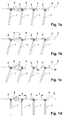
- Fig. 1a shows individual elements 1 of a cover of a first embodiment according to the invention in a sectional view.
- the elements 1 are in a first angular position.
- the elements 1 have a T-shaped cross-section.
- the rotational or pivot axis of the element 1 is shown, which extends perpendicular to the plane of the drawing.
- the elements 1 according to Fig. 1a are all in the same direction, ie in the same direction or in-phase, deflected and that by a first angle relative to the horizontal, which is identified by the reference numeral 3.
- the surface of the area extends around the cover, whereby a ground-level arrangement of the elements 1 is present.
- the elements 1 are at a greater angle relative to the horizontal 3 and in Figure 1c finally deflected by a predetermined maximum angle to the horizontal 3. Finally, the elements are 1 in Fig. 1d shown in a rest position or rest position, in which the surface 4 of the elements is aligned parallel to the horizontal 3.
- Fig. 2a shows a schematic representation in a sectional view of a second embodiment of a cover according to the invention 5.
- cover 5 only three elements 1 are arranged side by side. Two adjacent elements 1 in this case have a distance Z of 100 mm.
- the elements 1 are in Fig. 2a shown in three different pivoting positions, namely at 0 degrees, 18 degrees to the left, and 18 degrees to the right. The different pivot positions of the elements 1 are indicated with different hatchings.
- This in Fig. 2b enlarged element shown in a sectional view 1 has a substantially plate-shaped construction.
- Both the surface 4 forming the upper part 6 and the two side plates 7 may be formed of metal plates, which can be welded together for the manufacture or bent accordingly.
- the surface has a width B of 200 mm.
- In the Fig. 2a shown cover extends only over a range of 1100 mm.
- To the right of this, another cover (not shown) is provided, which together with the in Fig. 2a shown cover 5 covers an underlying space.
- the reference numeral 8 designates a part of the edge portion of the cover 5, namely, the part which is covered by the sectional view.
- the provided at the ends edge region (in Fig. 2a not shown) has corresponding bearing point, with which the elements 1 are rotatably mounted in each case about the axes of rotation 2.
- Fig. 3 shows in a schematic plan view of four side by side arranged covers 5, wherein the edge region of each cover 5 is also marked with the reference numeral 8.
- a truck 9 is with its rear on the left cover 5 and the rear side unload the bulk material on the elements 1 of the left cover 5. These are in this case set in motion, so that a possible volume-maximized bulk material flow fall into the provided under the cover 5 (not shown) receiving gutter fall or can be spent.
- the truck 10 (it could also be a railroad car) stands with its left side across to the four covers 5. The truck 10 will unload the bulk material laterally.
- Fig. 3 is removable that the truck 10 has traveled the covers 5 with the left wheels. Accordingly, the covers 5 and in particular the elements 1 have sufficient stability for this purpose. In other words, the elements 1 and their bearings on the edge region 8 are designed such that they satisfy such high static and dynamic load entries.
- Fig. 4a shows in a sectional view a schematic representation of a third embodiment of a cover according to the invention 5.
- the seventeen elements 1 are formed substantially triangular in this embodiment.
- the elements 1 are driven or moved by means of a transmission means 11 (namely, a strut on which the elements 1 are rotatably mounted at their lower portion) by the moving unit 12 having an electric motor and a transmission gear via a strut 14.
- the cover 5 according to Fig. 4a extends over a length of about 5600 mm in this embodiment.
- a receiving gutter or a pit 15 is provided, into which the bulk material (not shown) dropped on the cover falls down when the elements 1 of the cover 5 are moved.
- the bulk material in the pit 15 is then transported to its destination with a conveyor spiral, not shown.
- Fig. 4b shows the cover 5 from Fig. 4a in a supervision. It can be seen that the edge region 8 extends rectangularly or frame-like around the elements 1. Only schematically, it is indicated that the elements 1 are respectively rotatably mounted at opposite ends on the bearing points 13 at the opposite edge regions 8.
- the cover 5 according to Fig. 4a has a width of 5000 mm.
- Fig. 1c It is shown that the outer longitudinal edges of the elements 1 perform vertical movements during the pivoting movements. This vertical movement is indicated by the arrows 16. The vertical movements are greater, the greater the pivot angle of the elements 1.
Landscapes
- Engineering & Computer Science (AREA)
- Mechanical Engineering (AREA)
- Aviation & Aerospace Engineering (AREA)
- Catching Or Destruction (AREA)
- Auxiliary Methods And Devices For Loading And Unloading (AREA)
- Escalators And Moving Walkways (AREA)
- Filling Or Emptying Of Bunkers, Hoppers, And Tanks (AREA)
- Motorcycle And Bicycle Frame (AREA)
Abstract
Claims (15)
- Recouvrement (5) pour recouvrir un volume et/ou un espace (15), notamment un recouvrement de fosse, le recouvrement (5) comportant des éléments (1) mobiles, au moins une zone de bordure (8) et une unité de déplacement (12), les éléments (1) s'étendant au moins dans certaines zones au-dessus de l'espace (15) à recouvrir et étant disposés pour l'essentiel parallèlement les uns par rapport aux autres, les éléments (1) étant disposés respectivement de façon à pouvoir pivoter et/ou de façon à pouvoir basculer par rapport à la zone de bordure (8) et pouvant être déplacés par l'unité de déplacement (12), les éléments (1) comportant des surfaces (4) et un état de repos et les surfaces des éléments (1) étant orientées à l'état de repos pour l'essentiel horizontalement pour permettre de marcher et/ou de rouler sur le recouvrement, les éléments (1) étant dimensionnés et disposés de telle sorte les uns par rapport aux autres qu'il est possible de marcher et/ou de rouler sur les éléments (1), caractérisé en ce que les éléments (1) comportent une section transversale en forme de T, de triangle, de trapèze ou de polygone, que l'unité de déplacement (12) comporte un entraînement et un élément de transmission (11), que les éléments (1) puissent être entraînés par l'entraînement via l'élément de transmission pour provoquer une extraction de biens en vrac par le biais d'un mouvement de pivotement, de basculement ou de pendule à fréquence réglable, comportant de préférence un angle de déviation pouvant atteindre +/- 20 degrés.
- Recouvrement selon la revendication 1, caractérisé en ce que les éléments (1) peuvent être déplacés de telle sorte par l'unité de déplacement (12) que les éléments (1) réalisent un mouvement de même sens ou que des éléments (1) connexes réalisent respectivement un mouvement opposé.
- Recouvrement selon la revendication 1 ou 2, caractérisé en ce que les éléments (1) sont réalisés et/ou disposés de telle sorte qu'ils correspondent à des valeurs de charge statiques et/ou dynamiques élevées et qu'un élément peut par exemple absorber une valeur de charge pouvant atteindre 15 t.
- Recouvrement selon l'une quelconque des revendications 1 à 3, caractérisé en ce qu'un élément (1) présente une direction longitudinale, que l'axe de pivotement et/ou de basculement d'un élément (1) est disposé parallèlement à la direction longitudinale et que l'axe de pivotement et/ou de basculement est de préférence disposé à l'intérieur de la section transversale d'un élément (1) et/ou que la zone de bordure comporte un revêtement latéral (8) - de préférence orienté verticalement - qui s'étend sur une profondeur d'au moins 400 mm à partir de la surface des éléments (1) orientée vers les biens en vrac.
- Recouvrement selon l'une quelconque des revendications 1 à 4, caractérisé en ce que les éléments (1) sont réalisés, disposés et déplaçables de telle sorte qu'au moins un bord longitudinal de la partie de surface orientée vers les biens en vrac réalise au moins en partie un mouvement vertical (16) si les éléments (1) sont déplacés.
- Recouvrement selon l'une quelconque des revendications 1 à 5, caractérisé en ce qu'au moins un moyen de blocage est prévu permettant de bloquer les éléments (1) dans une position de repos et/ou qu'au moins un moyen de limitation est prévu permettant de limiter le mouvement des éléments (1).
- Recouvrement selon l'une quelconque des revendications 1 à 6, caractérisé en ce que dans l'état de repos des éléments (1), un espace intermédiaire (Z) de largeur prédéfinie est prévu entre deux éléments (1) connexes, ledit espace présentant de préférence une valeur située dans une plage comprise entre 80 et 150 mm.
- Recouvrement selon l'une quelconque des revendications 1 à 7, caractérisé en ce que la surface des éléments (1) opposée à l'espace (15) à recouvrir comporte une largeur (B) présentant de préférence une valeur située dans une plage comprise entre 150 et 250 mm et/ou que les éléments (1) présentent une longueur présentant une valeur située dans une plage comprise entre 3000 et 7000 mm.
- Recouvrement selon l'une quelconque des revendications 1 à 8, caractérisé en ce que la surface des éléments (1) orientée vers les biens en vrac comporte un revêtement antidérapant ou au moins un moyen antidérapant.
- Recouvrement selon l'une quelconque des revendications 1 à 9, caractérisé en ce qu'au moins deux recouvrements (5) sont disposés côte à côte pour recouvrir un espace (15), les éléments (1) des deux recouvrements (5) disposés côte à côte pouvant de préférence être déplacés de façon synchrone ou indépendamment l'un de l'autre.
- Recouvrement selon l'une quelconque des revendications 1 à 10, caractérisé en ce qu'un dispositif de commande est prévu lequel commande le déplacement des éléments (1) et le dispositif de commande dirigeant de préférence les éléments (1) en fonction des biens en vrac amenés sur le recouvrement de telle sorte que les biens en vrac traversent le recouvrement de façon optimisée dans le temps ou par rapport au débit ou qu'un débit volumique vertical prédéfini des biens en vrac traversant le recouvrement puisse être atteint et que le dispositif de commande permet de commander de telle sorte le déplacement des éléments (1) qu'un débit volumique prédéfini - de préférence pour l'essentiel constant - des biens en vrac traverse le recouvrement.
- Recouvrement selon l'une quelconque des revendications 1 à 11, caractérisé en ce que la fréquence du mouvement des éléments (1) présente une valeur prédéfinie située dans une plage comprise entre 0,1 Hz et 3 Hz et est de préférence de 1 Hz et/ou que la fréquence du déplacement des éléments (1) peut varier.
- Recouvrement selon l'une quelconque des revendications 1 à 12, caractérisé en ce qu'un élément de commande est prévu lequel permet de démarrer, d'arrêter et/ou de commander le déplacement des éléments (1) dans au moins deux modes de fonctionnement et l'élément de commande pouvant prendre la forme d'un contacteur de pied ou d'une télécommande (mobile).
- Recouvrement selon l'une quelconque des revendications 1 à 13, caractérisé en ce que les propriétés géométriques et/ou autres du recouvrement sont adaptées aux particularités liées à l'utilisation du recouvrement de biomasse ou de granulés de bois sous la forme de biens en vrac et/ou que les éléments (1) sont disposés au niveau du sol.
- Procédé d'exploitation d'un recouvrement (5) ou d'un recouvrement de fosse, notamment pour exploiter un recouvrement (5) selon l'une quelconque des revendications 1 à 14, le recouvrement (5) comportant des éléments (1) mobiles, au moins une zone de bordure (8) et une unité de déplacement (12), les éléments (1) s'étendant au moins dans certaines zones au-dessus de l'espace (15) à recouvrir et étant disposés pour l'essentiel parallèlement les uns par rapport aux autres, les éléments (1) étant disposés respectivement de façon à pouvoir pivoter et/ou de façon à pouvoir basculer par rapport à la zone de bordure (8) et pouvant être déplacés par l'unité de déplacement (12), les éléments (1) comportant des surfaces (4) et un état de repos et les surfaces des éléments (1) étant orientées à l'état de repos pour l'essentiel horizontalement pour permettre de marcher et/ou de rouler sur le recouvrement, les éléments (1) étant dimensionnés et disposés de telle sorte les uns par rapport aux autres qu'il est possible de marcher et/ou de rouler sur les éléments (1), caractérisé en ce que des biens en vrac sont posés sur le recouvrement (5) et que les éléments (1) sont déplacés de façon décalée les uns par rapport aux pour permettre de distribuer et/ou de faire passer les biens en vrac à travers le recouvrement (5).
Applications Claiming Priority (3)
| Application Number | Priority Date | Filing Date | Title |
|---|---|---|---|
| DE102007016349 | 2007-04-03 | ||
| DE102007024016A DE102007024016B3 (de) | 2007-04-03 | 2007-05-22 | Abdeckung und Verfahren zum Betreiben einer Abdeckung |
| PCT/EP2008/053969 WO2008119828A2 (fr) | 2007-04-03 | 2008-04-03 | Recouvrement et procédé permettant l'exploitation d'un recouvrement |
Publications (2)
| Publication Number | Publication Date |
|---|---|
| EP2129604A2 EP2129604A2 (fr) | 2009-12-09 |
| EP2129604B1 true EP2129604B1 (fr) | 2012-07-11 |
Family
ID=39105493
Family Applications (1)
| Application Number | Title | Priority Date | Filing Date |
|---|---|---|---|
| EP08735718A Active EP2129604B1 (fr) | 2007-04-03 | 2008-04-03 | Recouvrement et procede permettant l'exploitation d'un recouvrement |
Country Status (5)
| Country | Link |
|---|---|
| US (1) | US20100068017A1 (fr) |
| EP (1) | EP2129604B1 (fr) |
| DE (1) | DE102007024016B3 (fr) |
| RU (1) | RU2412890C1 (fr) |
| WO (1) | WO2008119828A2 (fr) |
Families Citing this family (1)
| Publication number | Priority date | Publication date | Assignee | Title |
|---|---|---|---|---|
| DE102009029405B8 (de) | 2009-09-13 | 2011-12-29 | Andreas Geisenheiner | Abdeckung, Grube und Verfahren zum Betreiben einer Abdeckung |
Family Cites Families (8)
| Publication number | Priority date | Publication date | Assignee | Title |
|---|---|---|---|---|
| US1676307A (en) * | 1926-03-08 | 1928-07-10 | Samuel C Clow | Grate for dump pits |
| DE1233305B (de) * | 1958-10-03 | 1967-01-26 | Wilson Bros Printers Pty Ltd | Verfahren und Vorrichtung zum Auftragen von Klebstoff auf Briefpapierbogen |
| DE2525703A1 (de) * | 1975-06-10 | 1976-12-23 | Schmidt Geb | Vorrichtung zum entstauben einer annahmegosse fuer schuettgueter, insbesondere getreide |
| DE3217542A1 (de) * | 1982-05-10 | 1983-11-10 | Willibald 8078 Eichstätt Schmidt | Vorrichtung zum absaugen von staub, der beim einschuetten eines schuettguts in eine gosse entsteht |
| US5205696A (en) * | 1990-05-14 | 1993-04-27 | Andreasen Norman H | Dumping system for a kiln floor |
| US5544686A (en) * | 1994-11-03 | 1996-08-13 | Agricultural Building Holdings, Inc. | Dust control system |
| RU2116953C1 (ru) * | 1997-07-08 | 1998-08-10 | Валерий Иванович Стуканов | Приемный бункер |
| US5893399A (en) * | 1997-12-22 | 1999-04-13 | Agricultural Building Company | Mechanism for reducing emissions of dust from grain bins |
-
2007
- 2007-05-22 DE DE102007024016A patent/DE102007024016B3/de not_active Expired - Fee Related
-
2008
- 2008-04-03 US US12/516,943 patent/US20100068017A1/en not_active Abandoned
- 2008-04-03 EP EP08735718A patent/EP2129604B1/fr active Active
- 2008-04-03 RU RU2009123310/11A patent/RU2412890C1/ru not_active IP Right Cessation
- 2008-04-03 WO PCT/EP2008/053969 patent/WO2008119828A2/fr not_active Ceased
Also Published As
| Publication number | Publication date |
|---|---|
| WO2008119828A2 (fr) | 2008-10-09 |
| EP2129604A2 (fr) | 2009-12-09 |
| US20100068017A1 (en) | 2010-03-18 |
| DE102007024016B3 (de) | 2008-03-27 |
| WO2008119828A3 (fr) | 2009-01-08 |
| RU2412890C1 (ru) | 2011-02-27 |
| RU2009123310A (ru) | 2010-12-27 |
Similar Documents
| Publication | Publication Date | Title |
|---|---|---|
| DE69822303T2 (de) | Teilweise einziehbare bauplattform | |
| EP3152141B1 (fr) | Gratteur portique présentant une structure de support se basant sur une structure en treillis | |
| DE4335456C2 (de) | Lastkraftwagen für den Transport von Gütern | |
| EP0523757B1 (fr) | Pont déplaçable | |
| EP1560730B1 (fr) | Vehicule a conteneurs de chargement ou plate-formes de chargement | |
| DE3332227C2 (de) | Brückenuntersichtgerät | |
| DE2748340C2 (de) | Kletterkran | |
| DE1784146B2 (de) | Mehrstoeckige speichereinrichtung fuer kraftfahrzeuge und andere gegenstaende | |
| EP2129604B1 (fr) | Recouvrement et procede permettant l'exploitation d'un recouvrement | |
| DE102019113845A1 (de) | Modulares Container-Raumsystem, Container-Basismodul und Container-Aufbaumodul | |
| WO1995028368A1 (fr) | Dispositif mobile pour le malaxage et/ou le retournage de materiaux (en meules) et dispositif d'evacuation utilise de preference a cet effet | |
| EP1888415B1 (fr) | Dispositif de transport conçu pour des elements de clôture et des pieds-supports | |
| EP0108292A2 (fr) | Revêtement enroulable pour aire de circulation | |
| EP2066538B1 (fr) | Portique de lavage et procédé de montage d'un portique de lavage | |
| DE2800226A1 (de) | Trimm- und loeschvorrichtung fuer schuettgut | |
| EP0885559A2 (fr) | Véhicule pour la distribution et le mélange de fourrage | |
| EP0389781A1 (fr) | Châssis de levage | |
| DE29911053U1 (de) | Streugerät | |
| DE102020120833B4 (de) | Anbauvorrichtung für einen Lastkraftwagen zum Aufbringen einer Deckschicht aus schüttfähigem Baumaterial auf einem Straßen- und/oder Wegeunterbau | |
| DE102005018424B4 (de) | Fördersystem zum gleichzeitigen Transport von Werkstücken und Monteuren in einer Fertigungslinie | |
| DE1657115C3 (de) | Bewegliche Großbrechanlage für Steinbruchbetriebe | |
| DE2150453A1 (de) | Arbeitsbuehne zum durchfuehren von arbeiten an hochbauten | |
| DE9308619U1 (de) | Lastkraftwagen | |
| DE3710285C2 (de) | Vorrichtung zum Abtragen von kontaminiertem Erdreich | |
| DE2927397A1 (de) | Ueberdachte mehretagen-hubgarage |
Legal Events
| Date | Code | Title | Description |
|---|---|---|---|
| PUAI | Public reference made under article 153(3) epc to a published international application that has entered the european phase |
Free format text: ORIGINAL CODE: 0009012 |
|
| 17P | Request for examination filed |
Effective date: 20090426 |
|
| AK | Designated contracting states |
Kind code of ref document: A2 Designated state(s): AT BE BG CH CY CZ DE DK EE ES FI FR GB GR HR HU IE IS IT LI LT LU LV MC MT NL NO PL PT RO SE SI SK TR |
|
| 17Q | First examination report despatched |
Effective date: 20110516 |
|
| GRAP | Despatch of communication of intention to grant a patent |
Free format text: ORIGINAL CODE: EPIDOSNIGR1 |
|
| DAX | Request for extension of the european patent (deleted) | ||
| GRAS | Grant fee paid |
Free format text: ORIGINAL CODE: EPIDOSNIGR3 |
|
| GRAA | (expected) grant |
Free format text: ORIGINAL CODE: 0009210 |
|
| AK | Designated contracting states |
Kind code of ref document: B1 Designated state(s): AT BE BG CH CY CZ DE DK EE ES FI FR GB GR HR HU IE IS IT LI LT LU LV MC MT NL NO PL PT RO SE SI SK TR |
|
| REG | Reference to a national code |
Ref country code: GB Ref legal event code: FG4D Free format text: NOT ENGLISH |
|
| REG | Reference to a national code |
Ref country code: CH Ref legal event code: EP |
|
| REG | Reference to a national code |
Ref country code: AT Ref legal event code: REF Ref document number: 566017 Country of ref document: AT Kind code of ref document: T Effective date: 20120715 |
|
| REG | Reference to a national code |
Ref country code: IE Ref legal event code: FG4D Free format text: LANGUAGE OF EP DOCUMENT: GERMAN |
|
| REG | Reference to a national code |
Ref country code: DE Ref legal event code: R096 Ref document number: 502008007695 Country of ref document: DE Effective date: 20120906 |
|
| REG | Reference to a national code |
Ref country code: NL Ref legal event code: VDEP Effective date: 20120711 |
|
| REG | Reference to a national code |
Ref country code: LT Ref legal event code: MG4D Effective date: 20120711 |
|
| PG25 | Lapsed in a contracting state [announced via postgrant information from national office to epo] |
Ref country code: LT Free format text: LAPSE BECAUSE OF FAILURE TO SUBMIT A TRANSLATION OF THE DESCRIPTION OR TO PAY THE FEE WITHIN THE PRESCRIBED TIME-LIMIT Effective date: 20120711 Ref country code: HR Free format text: LAPSE BECAUSE OF FAILURE TO SUBMIT A TRANSLATION OF THE DESCRIPTION OR TO PAY THE FEE WITHIN THE PRESCRIBED TIME-LIMIT Effective date: 20120711 Ref country code: FI Free format text: LAPSE BECAUSE OF FAILURE TO SUBMIT A TRANSLATION OF THE DESCRIPTION OR TO PAY THE FEE WITHIN THE PRESCRIBED TIME-LIMIT Effective date: 20120711 Ref country code: CY Free format text: LAPSE BECAUSE OF FAILURE TO SUBMIT A TRANSLATION OF THE DESCRIPTION OR TO PAY THE FEE WITHIN THE PRESCRIBED TIME-LIMIT Effective date: 20120711 Ref country code: IS Free format text: LAPSE BECAUSE OF FAILURE TO SUBMIT A TRANSLATION OF THE DESCRIPTION OR TO PAY THE FEE WITHIN THE PRESCRIBED TIME-LIMIT Effective date: 20121111 Ref country code: NO Free format text: LAPSE BECAUSE OF FAILURE TO SUBMIT A TRANSLATION OF THE DESCRIPTION OR TO PAY THE FEE WITHIN THE PRESCRIBED TIME-LIMIT Effective date: 20121011 |
|
| PG25 | Lapsed in a contracting state [announced via postgrant information from national office to epo] |
Ref country code: PT Free format text: LAPSE BECAUSE OF FAILURE TO SUBMIT A TRANSLATION OF THE DESCRIPTION OR TO PAY THE FEE WITHIN THE PRESCRIBED TIME-LIMIT Effective date: 20121112 Ref country code: LV Free format text: LAPSE BECAUSE OF FAILURE TO SUBMIT A TRANSLATION OF THE DESCRIPTION OR TO PAY THE FEE WITHIN THE PRESCRIBED TIME-LIMIT Effective date: 20120711 Ref country code: PL Free format text: LAPSE BECAUSE OF FAILURE TO SUBMIT A TRANSLATION OF THE DESCRIPTION OR TO PAY THE FEE WITHIN THE PRESCRIBED TIME-LIMIT Effective date: 20120711 Ref country code: SI Free format text: LAPSE BECAUSE OF FAILURE TO SUBMIT A TRANSLATION OF THE DESCRIPTION OR TO PAY THE FEE WITHIN THE PRESCRIBED TIME-LIMIT Effective date: 20120711 Ref country code: GR Free format text: LAPSE BECAUSE OF FAILURE TO SUBMIT A TRANSLATION OF THE DESCRIPTION OR TO PAY THE FEE WITHIN THE PRESCRIBED TIME-LIMIT Effective date: 20121012 Ref country code: SE Free format text: LAPSE BECAUSE OF FAILURE TO SUBMIT A TRANSLATION OF THE DESCRIPTION OR TO PAY THE FEE WITHIN THE PRESCRIBED TIME-LIMIT Effective date: 20120711 |
|
| PG25 | Lapsed in a contracting state [announced via postgrant information from national office to epo] |
Ref country code: NL Free format text: LAPSE BECAUSE OF FAILURE TO SUBMIT A TRANSLATION OF THE DESCRIPTION OR TO PAY THE FEE WITHIN THE PRESCRIBED TIME-LIMIT Effective date: 20120711 |
|
| PG25 | Lapsed in a contracting state [announced via postgrant information from national office to epo] |
Ref country code: CZ Free format text: LAPSE BECAUSE OF FAILURE TO SUBMIT A TRANSLATION OF THE DESCRIPTION OR TO PAY THE FEE WITHIN THE PRESCRIBED TIME-LIMIT Effective date: 20120711 Ref country code: EE Free format text: LAPSE BECAUSE OF FAILURE TO SUBMIT A TRANSLATION OF THE DESCRIPTION OR TO PAY THE FEE WITHIN THE PRESCRIBED TIME-LIMIT Effective date: 20120711 Ref country code: DK Free format text: LAPSE BECAUSE OF FAILURE TO SUBMIT A TRANSLATION OF THE DESCRIPTION OR TO PAY THE FEE WITHIN THE PRESCRIBED TIME-LIMIT Effective date: 20120711 Ref country code: RO Free format text: LAPSE BECAUSE OF FAILURE TO SUBMIT A TRANSLATION OF THE DESCRIPTION OR TO PAY THE FEE WITHIN THE PRESCRIBED TIME-LIMIT Effective date: 20120711 Ref country code: ES Free format text: LAPSE BECAUSE OF FAILURE TO SUBMIT A TRANSLATION OF THE DESCRIPTION OR TO PAY THE FEE WITHIN THE PRESCRIBED TIME-LIMIT Effective date: 20121022 |
|
| PLBE | No opposition filed within time limit |
Free format text: ORIGINAL CODE: 0009261 |
|
| STAA | Information on the status of an ep patent application or granted ep patent |
Free format text: STATUS: NO OPPOSITION FILED WITHIN TIME LIMIT |
|
| PG25 | Lapsed in a contracting state [announced via postgrant information from national office to epo] |
Ref country code: SK Free format text: LAPSE BECAUSE OF FAILURE TO SUBMIT A TRANSLATION OF THE DESCRIPTION OR TO PAY THE FEE WITHIN THE PRESCRIBED TIME-LIMIT Effective date: 20120711 Ref country code: IT Free format text: LAPSE BECAUSE OF FAILURE TO SUBMIT A TRANSLATION OF THE DESCRIPTION OR TO PAY THE FEE WITHIN THE PRESCRIBED TIME-LIMIT Effective date: 20120711 |
|
| 26N | No opposition filed |
Effective date: 20130412 |
|
| PG25 | Lapsed in a contracting state [announced via postgrant information from national office to epo] |
Ref country code: BG Free format text: LAPSE BECAUSE OF FAILURE TO SUBMIT A TRANSLATION OF THE DESCRIPTION OR TO PAY THE FEE WITHIN THE PRESCRIBED TIME-LIMIT Effective date: 20121011 |
|
| PGFP | Annual fee paid to national office [announced via postgrant information from national office to epo] |
Ref country code: CH Payment date: 20130423 Year of fee payment: 6 |
|
| REG | Reference to a national code |
Ref country code: DE Ref legal event code: R097 Ref document number: 502008007695 Country of ref document: DE Effective date: 20130412 |
|
| BERE | Be: lapsed |
Owner name: GEISENHEINER, ANDREAS Effective date: 20130430 |
|
| PG25 | Lapsed in a contracting state [announced via postgrant information from national office to epo] |
Ref country code: MC Free format text: LAPSE BECAUSE OF FAILURE TO SUBMIT A TRANSLATION OF THE DESCRIPTION OR TO PAY THE FEE WITHIN THE PRESCRIBED TIME-LIMIT Effective date: 20120711 |
|
| GBPC | Gb: european patent ceased through non-payment of renewal fee |
Effective date: 20130403 |
|
| REG | Reference to a national code |
Ref country code: IE Ref legal event code: MM4A |
|
| PG25 | Lapsed in a contracting state [announced via postgrant information from national office to epo] |
Ref country code: BE Free format text: LAPSE BECAUSE OF NON-PAYMENT OF DUE FEES Effective date: 20130430 Ref country code: GB Free format text: LAPSE BECAUSE OF NON-PAYMENT OF DUE FEES Effective date: 20130403 |
|
| REG | Reference to a national code |
Ref country code: FR Ref legal event code: ST Effective date: 20131231 |
|
| PG25 | Lapsed in a contracting state [announced via postgrant information from national office to epo] |
Ref country code: FR Free format text: LAPSE BECAUSE OF NON-PAYMENT OF DUE FEES Effective date: 20130430 |
|
| PG25 | Lapsed in a contracting state [announced via postgrant information from national office to epo] |
Ref country code: IE Free format text: LAPSE BECAUSE OF NON-PAYMENT OF DUE FEES Effective date: 20130403 |
|
| REG | Reference to a national code |
Ref country code: CH Ref legal event code: PL |
|
| PG25 | Lapsed in a contracting state [announced via postgrant information from national office to epo] |
Ref country code: LI Free format text: LAPSE BECAUSE OF NON-PAYMENT OF DUE FEES Effective date: 20140430 Ref country code: CH Free format text: LAPSE BECAUSE OF NON-PAYMENT OF DUE FEES Effective date: 20140430 |
|
| PG25 | Lapsed in a contracting state [announced via postgrant information from national office to epo] |
Ref country code: MT Free format text: LAPSE BECAUSE OF FAILURE TO SUBMIT A TRANSLATION OF THE DESCRIPTION OR TO PAY THE FEE WITHIN THE PRESCRIBED TIME-LIMIT Effective date: 20120711 |
|
| PG25 | Lapsed in a contracting state [announced via postgrant information from national office to epo] |
Ref country code: TR Free format text: LAPSE BECAUSE OF FAILURE TO SUBMIT A TRANSLATION OF THE DESCRIPTION OR TO PAY THE FEE WITHIN THE PRESCRIBED TIME-LIMIT Effective date: 20120711 |
|
| PG25 | Lapsed in a contracting state [announced via postgrant information from national office to epo] |
Ref country code: HU Free format text: LAPSE BECAUSE OF FAILURE TO SUBMIT A TRANSLATION OF THE DESCRIPTION OR TO PAY THE FEE WITHIN THE PRESCRIBED TIME-LIMIT; INVALID AB INITIO Effective date: 20080403 Ref country code: LU Free format text: LAPSE BECAUSE OF NON-PAYMENT OF DUE FEES Effective date: 20130403 |
|
| PGFP | Annual fee paid to national office [announced via postgrant information from national office to epo] |
Ref country code: AT Payment date: 20190416 Year of fee payment: 12 |
|
| REG | Reference to a national code |
Ref country code: AT Ref legal event code: MM01 Ref document number: 566017 Country of ref document: AT Kind code of ref document: T Effective date: 20200403 |
|
| PG25 | Lapsed in a contracting state [announced via postgrant information from national office to epo] |
Ref country code: AT Free format text: LAPSE BECAUSE OF NON-PAYMENT OF DUE FEES Effective date: 20200403 |
|
| REG | Reference to a national code |
Ref country code: DE Ref legal event code: R081 Ref document number: 502008007695 Country of ref document: DE Owner name: ANDRITZ AG, AT Free format text: FORMER OWNER: GEISENHEINER, ANDREAS, DR.-ING., 69198 SCHRIESHEIM, DE Ref country code: DE Ref legal event code: R082 Ref document number: 502008007695 Country of ref document: DE Ref country code: DE Ref legal event code: R081 Ref document number: 502008007695 Country of ref document: DE Owner name: MODUL SYSTEME ENGINEERING GMBH, DE Free format text: FORMER OWNER: GEISENHEINER, ANDREAS, DR.-ING., 69198 SCHRIESHEIM, DE |
|
| REG | Reference to a national code |
Ref country code: DE Ref legal event code: R081 Ref document number: 502008007695 Country of ref document: DE Owner name: ANDRITZ AG, AT Free format text: FORMER OWNER: MODUL SYSTEME ENGINEERING GMBH, 83410 LAUFEN, DE |
|
| PGFP | Annual fee paid to national office [announced via postgrant information from national office to epo] |
Ref country code: DE Payment date: 20250422 Year of fee payment: 18 |