EP2129015B1 - Audiosignalverarbeitungssystem - Google Patents
Audiosignalverarbeitungssystem Download PDFInfo
- Publication number
- EP2129015B1 EP2129015B1 EP20090154847 EP09154847A EP2129015B1 EP 2129015 B1 EP2129015 B1 EP 2129015B1 EP 20090154847 EP20090154847 EP 20090154847 EP 09154847 A EP09154847 A EP 09154847A EP 2129015 B1 EP2129015 B1 EP 2129015B1
- Authority
- EP
- European Patent Office
- Prior art keywords
- bus
- port
- track
- audio signal
- input device
- Prior art date
- Legal status (The legal status is an assumption and is not a legal conclusion. Google has not performed a legal analysis and makes no representation as to the accuracy of the status listed.)
- Not-in-force
Links
- 238000012545 processing Methods 0.000 title claims description 201
- 230000005236 sound signal Effects 0.000 title claims description 125
- 230000005540 biological transmission Effects 0.000 claims description 86
- 230000006870 function Effects 0.000 claims description 64
- 230000008859 change Effects 0.000 claims description 16
- 230000004044 response Effects 0.000 claims description 6
- 238000004891 communication Methods 0.000 description 28
- 238000010586 diagram Methods 0.000 description 12
- 230000008054 signal transmission Effects 0.000 description 12
- 238000000034 method Methods 0.000 description 6
- 230000000694 effects Effects 0.000 description 5
- 238000004091 panning Methods 0.000 description 4
- 230000002093 peripheral effect Effects 0.000 description 3
- 230000008569 process Effects 0.000 description 3
- 230000004397 blinking Effects 0.000 description 2
- 238000006243 chemical reaction Methods 0.000 description 2
- 238000013461 design Methods 0.000 description 2
- 230000004048 modification Effects 0.000 description 2
- 238000012986 modification Methods 0.000 description 2
- 238000003825 pressing Methods 0.000 description 2
- 230000003213 activating effect Effects 0.000 description 1
- 230000015572 biosynthetic process Effects 0.000 description 1
- 238000013500 data storage Methods 0.000 description 1
- 238000001514 detection method Methods 0.000 description 1
- 239000012636 effector Substances 0.000 description 1
- 230000008030 elimination Effects 0.000 description 1
- 238000003379 elimination reaction Methods 0.000 description 1
- 238000005516 engineering process Methods 0.000 description 1
- 230000004807 localization Effects 0.000 description 1
- 239000011159 matrix material Substances 0.000 description 1
Images


Classifications
-
- H—ELECTRICITY
- H04—ELECTRIC COMMUNICATION TECHNIQUE
- H04H—BROADCAST COMMUNICATION
- H04H60/00—Arrangements for broadcast applications with a direct linking to broadcast information or broadcast space-time; Broadcast-related systems
- H04H60/02—Arrangements for generating broadcast information; Arrangements for generating broadcast-related information with a direct linking to broadcast information or to broadcast space-time; Arrangements for simultaneous generation of broadcast information and broadcast-related information
- H04H60/04—Studio equipment; Interconnection of studios
Definitions
- the invention relates to an audio signal processing system provided with a signal input device transmitting a plurality of respective audio signals inputted from the outside to an audio signal processing device through a plurality of transmission ports and the audio signal processing device provided with a plurality of tracks for recording the audio signals, and also relates to computer readable medium embedding a program containing program instructions executable by a computer and a causing the computer to function as an audio signal processing device which can be included in the audio signal processing system.
- DAW Digital Audio Workstation
- a recording of audio signals supplied from an external device is performed on a track realized by the DAW application by connecting a PC activating the DAW application and a signal input device transmitting audio signals from a plurality of ports and inputting the signals into an external device (the PC here).
- the conventional DAW application is provided with a "virtual bus" function.
- This function is a function in which when audio waveform data inputted from an input terminal (which may be a terminal of a peripheral device) is received by any port at the time of inputting data, a bus (virtual bus) is first formed and is connected to the port, and the formed bus is designated to a track used for recording, as an input source of waveform data.
- a bus virtual bus
- a bus which can be formed and freely named by a user can be designated as an input source for a track. Therefore, even when set data of a track prepared in a certain hardware environment is used in another hardware environment, if only a connection between a port and a bus is set in accordance with the hardware environment, the setting of the track can be used without any change being made. Accordingly, by adopting the virtual bus function, it is possible to enhance an applicability and convenience of a system by facilitating a conversion of the set data of the track.
- Document 2 discloses another DAW. Therein, the use of multiple mLAN channels is described, wherein audio tracks are assigned to different buses and hence, separate mLAN output pairs.
- Document 2 Digital Mixing Studio 01X Owner's manual", [online], 2003, Yamaha, Internet ⁇ URL: http://www2.yamaha.co.jp/manual/pdf/emi/english/ synth/01x_en_om.pdf>
- Document 3 discloses a mixer system having a digital mixer processing waveform data in plural input channels and outputting the data via an ST bus, and a PC executing a DAW application realizing a function of plural tracks to record and reproduce waveform data. It is possible to set a first mode instructing the digital mixer to process waveform data inputted from outside the system in all input channels and the DAW application to mix the waveform data in all tracks to supply to the ST bus of the digital mixer, and a second mode instructing the digital mixer to process waveform data received from the DAW application in all input channels and the DAW application to send the waveform data in all tracks to corresponding input channels of the digital mixer.
- Document 3 EP 1 939 857 A2
- a setting of input source with respect to each track has been conventionally performed based on a name of a bus, so that a user has to determine that a bus to be set here as an input source for the track corresponds to which port or input terminal of a device being a physical signal supply source, and thus a difficulty in the setting has been high.
- An object of this invention is to solve such problems and to enable, even when audio signals transmitted from an external device are recorded in a plurality of tracks of an audio signal processing device, to easily recognize a correspondence between the tracks and the device being a signal supply source.
- This problem may similarly occur also in an audio signal processing device configured by using dedicated hardware.
- Another object of this invention is to solve such problems and to realize setting on a signal transmission path from an audio signal source to a track used to record the signal by simple operation, even when the audio signal processing device is provided with buses inputting audio signals transmitted from an external device and the bus should be set as an input source of the signals for a track which records the audio signal.
- an audio signal processing system of the invention includes: a signal input device that receives a plurality of audio signals from outside and transmits the plurality of audio signals to an audio signal processing device through a plurality of transmission ports in the signal input device; and an audio signal processing device including: a plurality of reception ports each of which receives an audio signal transmitted from the signal input device; a plurality of buses each of which is connected to one of the plurality of reception ports and receives the audio signal received by the one reception port; and a plurality of tracks each of which records the audio signal supplied from one of the plurality of buses, wherein the signal input device further includes: display devices corresponding to the plurality of transmission ports; and a display controller that controls the display devices according to control data received from the audio signal processing device, and wherein the audio signal processing device further includes: a memory that stores data indicating, regarding each one of the plurality of buses, one of the plurality of reception ports to which the one bus is connected, and one transmission port of the input device through which an audio signal received by the one
- the audio signal processing device further includes: a loading device that reads a project data including data of tracks and setting data of reception ports and buses, prepares the tracks, the reception ports, and the buses which connects the tracks and the reception ports based on the read project data; a second searching device that, when the loading device prepares the tracks, the reception ports, and the buses, searches any buses which supply audio signals to the prepared tracks; and a second control data transmitter that, when the second searching device finds one or more buses, judges if one or more reception ports connected to the found buses receive one or more audio signals transmitted through one or more transmission port of the signal input device or not based on the data stored in the memory and, when the judgment is affirmative, transmits, to the signal input device, second control data which instructs the display controller in the signal input device to control one or more display devices corresponding to the one or more transmission ports to indicate that the one or more transmission ports are connected to the prepared tracks.
- a loading device that reads a project data including data of tracks and setting data of reception ports and buses, prepares the tracks,
- the audio signal processing device further includes a changing device that changes an audio signal supply source for a track from one bus to another bus according to a user operation by stopping the one bus from supplying an audio signal to the track and start the other bus supplying an audio signal to the track; and a third control data transmitter that, in response to the change of the audio signal supply source for the track by the changing device, (a) judges, based on the data stored in the memory, if the one bus is connected to any reception port receiving an audio signal transmitted through a first transmission port of the signal input device or not and if the one bus no longer supplies the audio signal to any of the plurality of tracks after the change or not, and, when both of the two judgments are affirmative, transmits, to the signal input device, third control data which instructs the display controller in the signal input device to control one of the display devices corresponding to the first transmission port to indicate that the first transmission port is no longer connected to any of the tracks, and (b) judges, based on the data stored in the memory, if the
- a computer readable medium of the invention contains program instructions executable by a computer and causes the computer to function an audio signal processing device included in one of above described audio processing systems or capable of forming one of above described audio processing systems.
- FIG. 1 shows a functional configuration of a PC and a signal input device constituting an audio signal processing system as an embodiment of an audio signal processing system of the invention. Note that FIG. 1 simply shows functions of parts related to audio signal processing.
- a PC 10 as a general-purpose computer and a signal input device 30 are connected so that they can perform data transmission/reception via an audio LAN 50 and constitute an audio signal processing system 1.
- the PC 10 includes various audio I/Os (input/output units) 11, various audio I/O drivers 12, an API (Application Program Interface) 13 and a DAW (Digital Audio Workstation) application 20. Except for the various audio I/Os 11, those are functions realized by software. Description regarding hardware of the PC 10 will be given later.
- the various audio I/Os 11 are interfaces for transmitting/receiving data such as audio waveform data, MIDI (Musical Instruments Digital Interface: trademark) performance data and control data such as a command instructing a particular operation to a destination device.
- data such as audio waveform data, MIDI (Musical Instruments Digital Interface: trademark) performance data
- control data such as a command instructing a particular operation to a destination device.
- IEEE 1394 standard for mLAN communications which is an audio data communication standard proposed by Yamaha Corporation.
- USB standard or Ethernet registered trademark
- the various audio I/O drivers 12 have functions of driving the various audio I/Os 11 to make them communicate with an external device including the signal input device 30, which are realized by making a CPU execute a driver program.
- various MIDI drivers 12a with which transmission/reception of MIDI data is performed serial communication drivers 12b with which serial communication of arbitrary data is performed, and various WAVE drivers 12c with which transmission/reception of audio waveform data (hereinafter, if it is simply referred to as "waveform data", it indicates the audio waveform data) being a digital audio signal, are prepared.
- These drivers are activated when the PC 10 is turned on, and control input/output operations of the various audio I/Os. Further, when it is detected that an external device is connected to the audio LAN 50, an exchange of control signal is performed among the corresponding driver, the external device and other devices, and a virtual communication path according to a function of the external device is set between the PC 10 and the external device.
- a serial communication port included in the connected external device side is connected to the virtual communication path, and at the PC 10 side, a serial communication port is created by the serial communication driver 12b and connected to the virtual communication path.
- a waveform communication port (transmission port or reception port) included in the external device is connected to the virtual communication path, and at the PC 10 side, a waveform data communication port (reception port or transmission port) is created by the WAVE driver 12c and connected to the virtual communication path.
- MIDI communication ports are respectively connected at both the external device side and the PC 10 side in the same manner.
- the API 13 being a program interface provided by an OS (Operating System) can be used when operating an application program. Data transmitted/received by a driver among the various audio I/O drivers 12 is provided from or supplied to a bus and the like of the DAW application 20 via the API 13.
- OS Operating System
- the DAW application 20 has a function of, according to a user's operation, recording inputted waveform data or performance data, reading the recorded waveform data or performance data to output (reproduce), generating waveform data based on performance data (automatic performance), or performing mixing, equalizing, effect addition or the like on the waveform data (signal processing). These functions are realized by making a CPU of the PC 10 execute an appropriate application program.
- the DAW application 20 includes a GUI (Graphical User Interface) control module 21, a MIDI processing module 22, an audio processing module 23 and a remote control module 24.
- GUI Graphic User Interface
- the GUI control module 21 has functions of displaying a GUI on a display to accept a user's operation and displaying various pieces of information of the DAW application 20, such as set contents, operation states and contents of data being a processing target.
- the MIDI processing module 22 has a function of performing processing such as recording, reproducing and automatic performance on MIDI performance data.
- the audio processing module 23 has a function of performing processing such as recording, reproducing and signal processing on audio waveform data.
- the recording and reproducing in the MIDI processing module 22 and the audio processing module 23 can be performed by a plurality of tracks on a track-to-track basis.
- pieces of data of a plurality of channels, which are inputted from the signal input device 30 or the like can be individually inputted into different tracks to record, or pieces of data reproduced in the plurality of tracks can be outputted to destinations individually set for the respective tracks.
- the DAW application 20 is provided with a bus (virtual bus) for supplying waveform data received by the various audio I/Os 11 to a track.
- the bus has a function of receiving and inputting waveform data transmitted by an external device through a specific port and received by a specific reception port at the PC 10 side from the API 13 in accordance with a correspondence designated by later-described project data, and supplying the inputted waveform data to a specific track.
- the data to be transmitted is supplied to a transmission port via a bus, in the same manner.
- the remote control module 24 has a function of interpreting a command sent from an external device to change set contents in the DAW application 20, to start or stop operations, or to perform other operations according to the interpreted contents. Further, on the other hand, the remote control module 24 also has a function of transmitting, when a particular operation is performed on the DAW application 20 at the PC 10 side, control data according to the operation to the external device to make the external device operate according to the control data.
- control data may also be transferred through a serial communication using the serial communication drivers 12b.
- control data is generated as MIDI data and is transferred via control data communication ports prepared by the various MIDI drivers 12a.
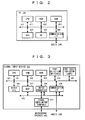
- FIG. 2 shows the hardware configuration of the aforementioned PC 10.
- the PC 10 can be configured by using a publicly-known PC as hardware.
- the PC 10 can be configured such that it includes a CPU 61, a ROM 62, a RAM 63, an HDD (hard disk drive) 64, a UI (user interface) 65 and a communication interface (I/F) 66 which are connected by a system bus 67.
- the CPU 61 executes an appropriate program stored in the ROM 62 or the HDD 64, it is possible to realize functions of the aforementioned respective modules.
- the UI 65 is an interface such as a display, a keyboard and a mouse for showing information to a user and accepting an operation from the user. It is of course possible to use devices external of the PC 10 as these interfaces.
- the communication I/F 66 includes the various audio I/Os 11 shown in FIG. 1 .
- FIG. 3 the hardware configuration of the signal input device 30 is shown in FIG. 3 . Further, a configuration of an operation panel of the signal input device 30 is shown in FIG. 4 .
- the signal input device 30 has a function of performing at least simple signal processing such as level adjustment on audio signals inputted through cables connected to signal input/output terminals 40 to transmit through a plurality of ports and inputting the transmitted audio signals into an external device such as the PC 10.
- the signal input device 30 includes a CPU 31, a ROM 32, a RAM 33, port selection switches 34, port state indicator lamps 35, other UIs 36, a DSP (digital signal processor) 37, an AD/DA converter 38 and a communication I/F 39 which are connected by a system bus 41. Further, the DSP 37, the AD/DA converter 38 and the communication I/F 39 are connected also by an audio bus 42 for transmitting waveform data.
- the signal input/output terminals 40 are connected to the AD/DA converter 38.
- functions of the CPU 31, the ROM 32 and the RAM 33 are similar to those in the aforementioned PC 10, and when the CPU 31 executes an appropriate program stored in the ROM 32, various control functions such as communication via the communication I/F 39, signal processing performed by the DSP 37, detection of operation of the port selection switches 34, lighting control of the port state indicator lamps 35 and later-described mode setting of ports are realized.
- the port selection switches 34 are controls provided so as to correspond to respective ports used for transmitting waveform data to an external device, and are used for selecting the respective ports. Hereinafter, if it is referred to as "switch" of the signal input device 30, it indicates the port selection switch 34, except when especially noted.
- the port state indicator lamps 35 are indicators provided so as to correspond to the respective ports used for transmitting waveform data to the external device, and are used for a display regarding states of the respective ports, especially a connection state between the ports and the external device.
- lamp of the signal input device 30, it indicates the port state indicator lamp 35, except when especially noted.
- the signal input device 30 is provided with eight ports used for transmitting waveform data to the external device in accordance with the number of signal input terminals, and on an operation panel 100, the port selection switches 34 and the port state indicator lamps 35 corresponding to the first to eighth ports are provided as switches having light emitting diode lamps included therein, as shown in FIG. 4 .
- the others UIs 36 are controls and indicators for setting processing contents in the DSP 37 and setting/displaying modes of respective ports.
- the other UIs 36 include level knobs 101 for individually setting levels of waveform data transmitted from the respective ports, a master level knob 102 for setting an output signal level as a whole device, and control element groups 103 and lamp groups 104 used for performing other various operations and displays.
- the DSP 37 is an audio signal processor performing level adjustment on waveform data inputted/outputted into/from an external device and performing panning when a port is in a stereo mode. Note that it is also possible that the DSP 37 conducts signal processing other than the above.
- the AD/DA converter 38 has a function of converting an analogue audio signal inputted from the signal input/output terminal 40 into digital waveform data or converting waveform data received from an external device via the communication I/F 39 into an analogue audio signal to supply to the signal input/output terminal 40.
- the signal input/output terminals 40 are terminals to input/output analogue audio signals via cables connected thereto. Further, it is of course possible to provide a terminal to input/output a digital audio signal, and in this case, it is only required to connect the terminal to the audio bus 42 without interposing the AD/DA converter 38 therebetween.
- the input/output terminal and a port is corresponded one-to-one, in which, for example, one port for transmitting signal is provided with respect to one signal input terminal, and waveform data relating to an analogue audio signal inputted from the terminal is outputted from the corresponding port.
- the communication I/F 39 is an interface for transmitting/receiving waveform data to/from an external device such as the PC 10 by being connected to the audio LAN 50, and an interface of appropriate standard can be adopted, similar to the case of the PC 10.
- respective output ports can be operated in either monaural mode or stereo mode.
- monaural mode monaural waveform data is transmitted from each port
- stereo mode pieces of stereo waveform data of two channels of L and R are transmitted from two ports being paired with each other.
- level adjustment thereof can be collectively conducted and panning adjustment can be performed thereon.
- the adjacent (2n-1)-th port and 2n-th port are set to be a pair (stereo pair) in this embodiment.
- This embodiment is characterized by a function regarding a setting and a display of data transmission paths when pieces of waveform data transmitted from a plurality of ports by the signal input device 30 such as described above and inputted into the PC 10 are recorded in a plurality of tracks of the DAW application 20. Accordingly, this function will be described hereinbelow.
- the pieces of waveform data are received by reception ports corresponding to the transmission ports at the signal input device 30 side prepared by the WAVE drivers 12c.
- the PC 10 can receive pieces of waveform data from a plurality of signal input devices 30, and in this case, reception ports are prepared for every device being waveform data transmission source. Further, even when pieces of waveform data are received from a plurality of the same model of signal input devices 30, the WAVE drivers 12c can distinguish respective devices based on a connection order of a chain connection, an IP address, a MAC address or the like, and can recognize that each of the reception ports corresponds to which port of which device.
- Input buses 25, an input patch 26 and audio tracks 27 shown in FIG. 5 are functions provided by the DAW application 20.
- the input buses 25 input pieces of waveform data received by specific reception ports designated by later-described project data.
- Arrows illustrated in a box of the API 13 in FIG. 5 indicate a correspondence between buses and reception ports being input sources.
- the input bus 25 includes two types of monaural bus (MO_Inx) and stereo bus (ST_Inx).
- the monaural bus inputs waveform data transmitted from one port of the signal input device 30 and received by one reception port of the PC 10 as monaural waveform data.
- the stereo bus inputs pieces of waveform data transmitted from two ports of the signal input device 30 and received by two reception ports of the PC 10 as stereo waveform data of two channels.
- each reception port can be connected to only one bus, and each bus can be connected to only one (one for each of channels in a case of stereo bus) reception port. Accordingly, when a certain bus is connected to a certain reception port, a connection between the certain reception port and a bus to which the reception port was connected is cut off.
- reception port which is not connected to any bus or a bus which is not connected to any reception port may exist. Further, these regulations are not mandatory as will be described later in a modified example.
- the input patch 26 has a routing function which supplies waveform data inputted into a specific input bus to a specific audio track in accordance with contents of later-described project data. Arrows illustrated in a box of the input patch 26 in FIG. 5 indicate a correspondence between buses and reception ports being input sources.
- connection between a track and a bus it is possible to connect one bus to a plurality of tracks, but, it is not possible to connect one track to a plurality of buses. Further, a bus which is not connected to any track or a track which is not connected to any bus may also exist. Furthermore, a type (monaural/stereo) of bus and track does not always have to be considered at the time of connection. This point will be described later.
- the audio track 27 is a track described in the explanation of the audio processing module 23 in FIG 1 , and has a function of at least recording waveform data inputted therein. Further, it is also possible to create an arbitrary number of audio tracks 27 automatically or in accordance with an instruction from a user as long as a capacity of hardware of the PC 10 allows.
- the audio track 27 also has two types of monaural track (Tr_Mox) and stereo track (Tr_STx).
- the monaural track inputs monaural waveform data of one channel to record the data
- the stereo track inputs stereo waveform data of two channels of L and R and records the data in each channel.
- a monaural track is for recording waveform data inputted from a monaural bus and a stereo track is for recording waveform data inputted from a stereo bus, but, it is not limited to this.
- waveform data from a monaural bus is inputted into a stereo track, it is only required to input the same waveform data into both channels of L and R of the track.
- pieces of waveform data from a stereo bus are inputted into a monaural track, it is only required to select and input waveform data of either bus of L and R.
- the audio signal processing system 1 through a transmission path such as described above, it is possible to input audio signals inputted from respective input terminals of the signal input device 30 into the desired audio tracks 27 via the input buses 25 to record the signals.
- a transmission port or an input terminal at the signal input device 30 side being a supply source of the waveform data inputted into the track can be specified.
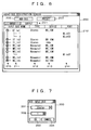
- FIG. 6 shows a display example of a screen for performing a setting regarding the aforementioned input bus 25.
- An audio bus registration screen 200 shown in FIG. 6 is a GUI (graphical user interface) to be displayed on a display of the PC 10, and is a screen for giving an instruction regarding creation and elimination of the input bus 25 shown in FIG. 5 , setting of connection of the input bus 25 to a reception port, and the like.
- GUI graphical user interface
- the audio bus registration screen 200 includes an input/output selection tab 201, a bus addition button 202, a preset read button 203 and a bus list display part 210.
- the input/output selection tab 201 is a button for selecting whether to display information on input buses shown in FIG. 5 or information on not-shown output buses in the bus list display part 210.
- the output bus has no particular relation to the characteristic of this embodiment, so that detailed explanation thereof will be omitted.
- the bus addition button 202 is a button for instructing an addition of buses.
- a bus which can be added by clicking this button is a bus of a type selected by the input/output selection tab 201 (input bus in an example in the drawing).
- a setting of input buses to be set on this screen is stored in a preset memory by selecting "save" from a menu which is displayed when right-clicking on the screen.
- the preset read button 203 is a button for selecting a preset in the preset memory. When this button is clicked, presets in the preset memory are list-displayed, and by selecting a desired preset among them, the setting stored in the selected preset can be reflected to the setting of current input buses.
- the bus list display part 210 is a display part showing, as a list form, information on buses of a type selected by the input/output selection tab 201 among buses currently existing in the DAW application 20.
- a bus name display portion 211 a bus type display portion 212, a connection device display portion 213 and a connection port display portion 214 are included.
- the bus name display portion 211 is a display portion for displaying a bus name.
- the name may be set automatically or by a user.
- the bus type display portion 212 is a display portion for displaying a type (monaural/stereo) of bus.
- the type is decided when the bus is created, and cannot be changed thereafter.
- the connection device display portion 213 is a display portion for displaying a name of device (signal input device 30 or the like) which supplies waveform data inputted into a bus.
- the information cannot be changed independently, and when a port of connection destination is designated, the information is automatically set according thereto.
- the name of device is not necessarily to be the one by which an individual can be identified, and may be a name of a model or a manufacturer, or information indicating a position of device such as an address.
- the connection port display portion 214 is a display portion for displaying an ID of reception port connected to a bus. Note that the port ID is displayed by being corresponded, not to the entire bus, but to respective channels in the bus.
- the bus list display part 210 includes deployment buttons 215 on the left side of the screen corresponding to respective buses, in which when the button is in a state of "+”, only information on the entire bus is displayed, and by clicking the button to turn it into "-”, information regarding respective channels in the bus can be displayed. In a monaural bus, there is only one channel for one bus, but, in a stereo bus, there are two channels of L and R, as shown in a field of ST_In1.
- connection destination port corresponding to each channel in the connection port display portion 214 it is possible to display a list of reception ports capable of being connected to the bus and to select a port from the list to set it as a connection destination. According to the setting, the name of device displayed on the connection device display portion 213 is automatically set.
- the respective port IDs and the names of devices are automatically decided based on the functions of the WAVE drivers 12c, and how to name them depends on the functions of the drivers.
- a number may simply be designated, or an ID including a name of connection destination device may be designated after the name is confirmed. In either case, it is conceivable that an ID by which a correspondence between a port and a terminal at the signal input device 30 side can be grasped to some extent is normally designated.
- FIG. 7 a display example of a screen for instructing an addition of input bus is shown in FIG. 7 .
- An input bus addition screen 300 shown in FIG. 7 is also a GUI to be displayed on the display of the PC 10, and is a screen for instructing an addition of the input bus 25.
- the input bus addition screen 300 includes a bus type designation portion 301, a bus number designation portion 302, an OK button 303 and a cancel button 304.
- the bus type designation portion 301 and the bus number designation portion 302 are respectively portions for accepting designations regarding the type and the number of buses to be added. Further, by clicking the OK button 303 after these designations are made, it is possible to add the bus with the type and the number according to the designated contents.
- connection destination since a port of a connection destination is not set at this moment, in order to input waveform data into the created bus, there is a need to set the connection destination on the audio bus registration screen 200.
- the input bus addition screen 300 is closed without conducting the addition of buses to return to the audio bus registration screen 200.
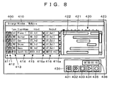
- FIG. 8 shows a display example of a screen for conducting a setting regarding the aforementioned tracks.
- a track control screen 400 shown in FIG. 8 is also a GUI to be displayed on the display of the PC 10, and is a screen for conducting a setting regarding the aforementioned tracks.
- the track control screen 400 includes a track setting window 410 and a recording and reproducing window 430.
- the track setting window 410 is a screen provided for performing setting related not only to the audio tracks 27 shown in FIG. 5 but also to the MIDI tracks provided in the MIDI processing module 22 for handling MIDI data.
- the track setting window 410 includes a one-line length setting and displaying field for each created track in order to accept settings regarding the corresponding tracks and display the information.
- a recording standby button 411 In each line of the track setting window 410, a recording standby button 411, a mute button 412, a type display portion 413, a name set portion 414, an input source bus set portion 415 and an output destination bus set portion 416 are provided.
- the recording standby button 411 is a button for switching by toggling between a recording standby state and a released state of each track.
- the mute button 412 is a button for switching by toggling between mute on and off of each track.
- the type display portion 413 is a display portion for displaying whether the type of the track is a monaural track (MO) or a stereo track (ST) of an audio track, or a MIDI track (MIDI).
- MO monaural track
- ST stereo track
- MIDI MIDI track
- the name set portion 414 is a region for inputting and setting names of tracks.
- the input source bus set portion 415 is a region for setting an input bus to be connected to each track via the input patch 26. By clicking a pull-down button 415a, it is possible to display a list of currently existing input buses and to select and set a bus of connection destination among them. Note that an audio track can be connected only to an audio bus, and a MIDI track can be connected only to a MIDI bus.
- the output destination bus set portion 416 is a region for setting an output destination of waveform data from each track. Although an illustration is omitted in FIG. 5 , waveform data inputted into each audio track or waveform data reproduced in each audio track can be transmitted to the signal input device 30 and outputted from an output terminal via an output bus and an output port along the path similar to that at the time of input shown in FIG. 5 but in nearly opposite direction.
- the output bus to be an output destination of the waveform data can be set in the output destination bus set portion 416.
- This setting can be realized by clicking a pull-down button 416a to display a list of currently formed output buses and selecting a bus of connection destination among them. At this time, it is also possible to set output destinations of a plurality of tracks to the same bus, and in this case, pieces of waveform data from the plurality of tracks are mixed in the bus and then supplied to the next stage. Note that also regarding the output, an audio track can be connected only to an audio bus and a MIDI track can be connected only to a MIDI bus.
- FIG. 8 An example shown in FIG. 8 illustrates a state where input buses ST_In1, MO_In3, ST_In2, MO_In2 and MO_In2 being input sources (fourth and fifth input buses are the same input source) and an output bus ST_Out1 being an output destination are set for five audio tracks from the top.
- the track setting window 410 also has a track content indicator 420.
- the track content indicator 420 is a portion indicating a data storage condition and a recording and reproducing status in each track.
- the abscissa axis represents time.
- Bars 421 represent time periods of recorded data.
- a cursor 422 indicates a position to start recording or reproducing or an executing position.
- a slider 423 and scroll buttons above and under the slider 423 are used to scroll the screen and change tracks to be displayed on the track setting window 410.
- the recording and reproducing window 430 is a window for accepting an operation to start and stop recording or reproducing.
- a fast-rewind button 431 and a fast-forward button 432 are respectively used to start fast-rewinding and fast-forwarding.
- a stop button 433 is used to stop reproducing, recording, fast-rewinding and fast-forwarding.
- the start button 434 is used to start reproducing and recording.
- the recording button 435 is used to switch, by toggling, the function of pressing the start button 434 between start of reproducing and start of recording.
- a recording and reproducing position indicator 436 is a portion for showing the position indicated by the cursor 422 as time from the beginning of the track.
- FIG. 9 a configuration example of project data is shown in FIG. 9 .
- the project data is used for managing an audio track and an MIDI track, and indicates set contents of transmission paths of data in the DAW application 20 and information on respective devices which communicate with the DAW application 20. It is possible to store project data at a specific moment, as a project file, to the HDD 64 of the PC 10, a detachable recording medium such as a USB memory or a memory card, a recording medium of an external device capable of communicating with the PC 10, or the like. In addition, it is also possible to reflect set contents at the time of storing the data on an operation of the DAW application 20 by reading the project data from the project file in accordance with an instruction from a user.
- the project data concretely includes a header, audio track data, MIDI track data, input bus data, other bus data, connection destination device data and other data.
- the audio track data, the input bus data and the connection destination device data relate to the characteristic of this embodiment, so that further detailed explanation thereof will be given.
- the audio track data is data specifying a name, a connection destination, signal processing contents and the like of each audio track existing (used) in the DAW application 20.
- the audio track data includes, for each audio track, a track ID, a track name, a track type, an input source bus ID (and channel), an output destination bus ID, a level, a pan, a region list and other data.
- the track ID, the track name and the track type are data indicating an ID of the track, data indicating a name of the track and data indicating whether the track is stereo or monaural, respectively.
- the input source bus ID and the output destination bus ID are respectively an ID of an input bus from which waveform data is inputted into the relevant track and an ID of an output bus to which the waveform data is outputted from the relevant track. These IDs are specified by using later-described bus IDs. Further, when a stereo input bus is connected to a monaural track, not only the input source bus ID but also a signal of either L or R channel to be inputted into the track is specified.
- the level and the pan are parameters indicating contents of level adjustment and panning (only when the track is a stereo track) performed on output data when the waveform data is outputted from the track.
- the region list specifies information on a reproduction start time of each region on the time axis of the track, a waveform file name, a reproduction range in the file and the like, as information on each time domain (region) during which waveform data is recorded in the relevant track.
- one waveform file is newly formed in the HDD 64. Audio signals inputted into the track are recorded in the waveform file, and pieces of data regarding a reproduction start time, a name of the waveform file, a reproduction range indicating a range of waveform in the file to be reproduced, and the like, are added in the region list. Through the processes, the audio signals recorded in the waveform file are additionally arranged on the time axis of the track.
- the data regarding the reproduction start time, the waveform file name, the reproduction range and the like of each region are sequentially read from the region list of the track in an order of early reproduction start time, and at a timing indicated by the reproduction start time, waveform in a range indicated by the reproduction range in the waveform file indicated by the waveform file name is read to be reproduced.
- the input bus data is data specifying a name, a connection destination, signal processing contents and the like of each input bus for transferring waveform data existing (used) in the DAW application 20.
- the input bus data includes, for each input bus, a bus ID, a bus name, the number of channels, a signal input source port ID, a level, a pan and the other data.
- the bus ID and the bus name are data indicating an ID and a name of the bus, respectively.
- the number of channels indicates the number of channels (referred to as Nc) of waveform data transferred by the relevant bus, and is data substantially indicating a type of the bus. Specifically, when the number of channels is 1, the bus is a monaural bus and when the number of channels is 2, the bus is a stereo bus.
- Nc is 1 or 2, but, it is of course conceivable to form buses with Nc of 3 or more.
- the signal input source port ID is an ID of reception port to be an input source of waveform data to the relevant bus.
- an ID of the input source port is individually specified for each channel. Note that if the connection destination device data is searched using the port ID as a key, it is possible to confirm that the port relating to the ID is used for communication with which device.
- the level and the pan are parameters indicating contents of level adjustment and panning (only when the bus is a stereo bus) performed on output data when the waveform data is outputted from the bus.
- connection destination device data is data specifying, for each device communicating with the PC 10 and inputting and/or outputting data into and/or from the DAW application 20, a name, a port used to communicate with the device, and the like.
- connection destination device data includes, for each device, a device ID, a device name, a type, a control port ID, audio port information, MIDI port information, and other data.
- the device ID, the device name and the type respectively indicate an ID, a name and a type of the relevant device. Further, the device ID is an ID by which the DAW application 20 can uniquely specify each device.
- the name is a name to be displayed on the connection device display portion 213 on the screen shown in FIG. 6 .
- the type is data indicating a model of the device.
- the control port ID is an ID of a port used for transmitting/receiving control data to/from the relevant device.
- the audio port information is information on a port used for transmitting/receiving waveform data to/from the relevant device. More concretely, the audio port information includes the number Npr of ports used for receiving the waveform data, the number Npt of ports used for transmitting the waveform data and port IDs of the respective ports. If only either the transmission or reception is performed, Npr or Npt may become zero.
- the MIDI port information is information on a port used for transmitting/receiving MIDI data (except the one to be transmitted/received as control data) to/from the relevant device.
- the form thereof is the same as that of the audio port information.
- the respective port IDs are IDs allocated by an OS to the communication ports when the ports are created by the various I/O drivers 12.
- the OS does not allocate the same ID to a different port.
- a device connected to the audio LAN 50 as a connection destination device includes a model capable of automatically setting contents of the connection destination device data shown in FIG. 9 through a communication between the DAW application 20 and the connection destination device itself (automatic setting type) and a model which cannot perform the automatic setting (manual setting type).
- the DAW application 20 performs, when it is activated or the connection destination device is connected, a communication with the connection destination device via a control port to obtain the device ID, the device name, the type, Npr and Npt respectively being the number of reception ports and transmission ports for audio and MIDI reception ports, and registers them as one piece of device data of the connection destination device data shown in FIG 9 .
- the DAW application 20 obtains, from the connection destination device, information indicating each transmission port and reception port included in the connection destination device are connected to which virtual communication path on the audio LAN 50, discriminates, based on the information, the transmission port and the reception port are connected to which reception port and transmission port of the various I/O drivers 12, and registers information indicating the discriminated ports.
- data of the corresponding device is manually registered by a user. Note that in this example, it is assumed that data of all devices connected to the audio LAN 50 is correctly registered.
- connection destination device data reflects a connection state of the device at the time of storing the project data, there is no assurance that the connection state matches an actual connection state of the device when reading the project data. Accordingly, when reading the project data, the DAW application 20 does not reflect the connection destination device data itself on its operation, and compares the connection destination device data held by the driver or the OS with contents of the read project data.
- the DAW application 20 reflects the signal input source port ID among the input bus data on its operation only to the extent in which the connection destination device data stored as the project data matches the data held by the driver or the OS when reading the project data, and regarding items in which they do not match, the DAW application 20 considers that no input source port for the bus exists, namely, a connection between the bus and the reception port is cut off.
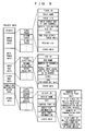
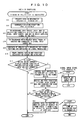
- FIG. 10 shows a flowchart of processing when a reading instruction of the project file is issued.
- the CPU 61 of the PC 10 starts the processing in the flowchart at the left side of FIG. 10 .
- the CPU 61 reads out the project data in the project file designated to be read (S11), and makes inquiries to the driver or the OS to check reception ports which currently exist (S12).
- the CPU 61 creates input buses specified in the input bus data and connects each of the created buses to a reception port being a signal input source (S13).
- the input bus is required to be connected only to a port which currently exists among the ports specified by the signal input source port IDs in the project data, as described above. Further, by connecting the bus to the reception port, the bus is also connected indirectly to a device which supplies a signal to the port.
- the CPU 61 creates tracks specified in the audio track data, and connects each of the created tracks to a signal input source bus (S14).
- the CPU 61 also reflects the contents of project data regarding the other portions on the signal processing in the DAW application 20 (S15). Although detailed explanation is omitted, this processing includes a connection between a track and an output port, a formation of MIDI data transmission path and the like.
- the CPU 61 serves as a reflecting device.
- the CPU 61 displays the track control screen 400 shown in FIG. 8 and the audio bus registration screen 200 shown in FIG. 6 on the display based on the set contents set by the processing so far (S16).
- the CPU 61 discriminates whether or not there exists a device which supports a display control function of the DAW application 20 among signal input devices connected to the PC 10 (S17). This determination can be made by comparing model information on the connection destination device with a previously stored list of model supporting the display control function, or by making inquiries to the connection destination device. Further, the display control function described here is a function of controlling display contents of an indicator (lamp 35 in this case) corresponding to a port included in the destination device. This point applies to the description hereinbelow as well except when especially noted.
- a certain device supports the display control function concretely means that the device can interpret control data for controlling display contents of the indicator transmitted from the DAW application 20 and can execute processing according thereto. If a protocol of the control data differs by each model, the DAW application 20 is only required to transmit control data according to the protocol corresponding to the device.
- step S 17 If it is YES in step S 17, namely, when a device supporting the display control function of the DAW application 20 is found, the CPU 61 transmits control data instructing to turn off all the lamps to the found device (S18).
- the CPU 31 When the signal input device 30 supporting the display control function receives the control data, the CPU 31 starts the processing in the flowchart at the right side of FIG. 10 , and turns off the lamps 35 of all the ports (S31). Arrows in the drawing indicate that a device starts top side processing upon receiving data transmitted in bottom side step. This applies to the drawings hereinbelow as well.
- step S18 the CPU 61 searches, for each of the currently existing audio tracks, a device and a port connected to the signal input source bus (S19).
- the connection destination device data shown in FIG. 9 and a setting of input source for each audio track, a signal input device and its transmission port being supply sources of waveform data inputted into each audio track are specified by following the arrow indicating the signal transmission path shown in FIG. 5 from each of the audio tracks in the opposite direction.
- control data (second control data) instructing to turn on lamps of the respective found ports to the respective found devices (S21), and terminates the processing.
- the CPU 31 turns on the lamp 35 of the designated port (S32).
- step S17 If it is NO in step S17 or it is NO in step S20, the CPU 61 cannot control the display in the connection destination device even if the control data is transmitted, and thus there is no point in conducting the processing, so that the processing is terminated.
- the CPU 61 serves as a second searching device in step S 19, and it serves as a second control data transmitter in steps S20 and S21. Further, in steps S31 and S32, the CPU 31 serves as a display controller.
- the DAW application 20 reads the project file and changes configurations of tracks and buses in accordance with the data of the file, it is possible to make an indicator corresponding to a port being a supply source to supply waveform data to at least one track, of each of signal input devices (among them, a device supporting the display control function) connected to the PC 10, perform a display indicating that the waveform data outputted from the port is supplied to at least the one track (to turn on a lamp, in this case).
- a user can easily recognize a connection state between a track and a signal input device such as that a cable is to be connected to which terminal when waveform data is recorded in a track or whether a desired port is connected to the track, regardless of a configuration of a signal transmission path therebetween.
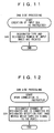
- FIG. 11 shows a flowchart of processing when creation of an input bus is instructed.
- the CPU 61 of the PC 10 starts the processing in the flowchart of FIG. 11 .
- the CPU 61 creates the designated type and the designated number of input buses (S41), and terminates the processing.
- it is not particularly required to connect a bus and a reception port.
- FIG. 12 shows a flowchart of processing when connection of a reception port to an input bus is instructed.
- the CPU 61 of the PC 10 starts the processing in the flowchart of FIG. 12 .
- the CPU 61 connects the designated channel of the designated input bus to the designated reception port (S51), and terminates the processing.
- the designated input bus is also connected indirectly to a device which supplies a signal to the reception port of the connection destination.
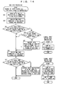
- FIG. 13 shows a flowchart of processing when selection of an audio track is instructed.
- the CPU 61 of the PC 10 starts the processing in the flowchart at the left side of FIG. 13 . Note that regarding the selection of tracks, only one track can be selected by clicking on a display of track or a plurality of tracks can be simultaneously selected by specifying a range.
- the CPU 61 first sets a track relating to the selection in a selected state (S61). Subsequently, the CPU 61 searches, for each audio track in the selective state, a device and a port connected to a signal input source bus based on the input bus data and the connection destination device data shown in FIG. 9 (S62). The search is performed in the same manner as in step S 19 in FIG. 10 .
- control data instructing to blink lamps of the respective found ports to the respective found devices (S64), and terminates the processing.
- the CPU 31 When the signal input device 30 supporting the display control function receives the control data, the CPU 31 starts the processing in the flowchart at the right side of FIG. 13 , and after blinking the lamp 35 of the designated port for a predetermined period of time, the CPU 31 turns on the lamp of the same port (S71 and S72).
- step S63 the CPU 61 cannot control the display in the connection destination device, so that the processing is terminated directly.
- the CPU 61 serves as a selecting device and a searching device in steps S61 and S62, respectively, and it serves as a control data transmitter in steps S63 and S64. Further, the CPU 31 serves as a display controller in steps S71 and S72.
- an indicator corresponding to a port being a supply source to supply waveform data to at least one track among the selected audio tracks perform a display indicating that the port corresponds to the track (to blink a lamp, in this case).
- a display indicating that the port corresponds to the track to blink a lamp, in this case.
- a user can easily recognize, by the aforementioned display, a connection state between a desired track and a signal input device, regardless of a configuration of a signal transmission path therebetween.
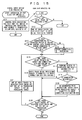
- FIG. 14 shows a flowchart of processing when change of an input source bus for an audio track is instructed.
- the CPU 61 first connects a track relating to the instruction to the bus after the change (S81). Subsequently, the CPU 61 searches a device and a port connected to the input source bus before the change (S82). The search is performed in the same manner as in step S19 in FIG. 10 .
- the CPU 61 finds a port of device supporting the display control function of the DAW application 20 (YES in S83) and if the original bus is no longer connected to any audio tracks (NO in S84), the CPU 61 transmits control data (third control data) instructing to turn off a lamp of the found port to the found device (S85).
- the CPU 31 starts the processing in the flowchart at the right side of FIG. 14 , and turns off the lamp 35 of the designated port (S91).
- step S84 since the display indicating that the waveform data from the relevant port is still supplied to at least one track is kept displayed, the processing of step S85 is not conducted. If it is NO in step S83, it is not possible to control the display in the connection destination device, so that also in this case, the processing of step S85 is not conducted.
- the CPU 61 next searches a device and a port connected to the input source bus after the change (S86). The search is also performed in the same manner as in step S 19 in FIG. 10 .
- the CPU 61 finds a port of device supporting the display control function of the DAW application 20 (YES in S87), it transmits control data (fourth control data) instructing to blink a lamp of the found port to the found device (S88), and terminates the processing.
- step S87 it is not possible to control the display in the connection destination device, so that the processing is terminated.
- the CPU 61 serves as a changing device in step S81, and it serves as a third control data transmitter in steps S82 to S88. Further, the CPU 31 serves as a display controller in steps S71, S72 and S91.
- an indicator corresponding to a port newly made to be a supply source to supply waveform data to an audio track relating to the instruction at the time of changing the connection destination perform a display indicating that the waveform data outputted from the port is newly supplied to the audio track (to blink a lamp, in this case).
- this port was not a supply source to supply waveform data to any audio tracks before the connection destination was changed, the display at the lamp is changed in an order of the light-off state, the light-blinking state and the light-on state.
- this port was a supply source to supply waveform data to some audio track before the connection destination was changed, the display at the lamp is changed in an order of the light-on state, the light-blinking state and the light-on state.
- a user can easily recognize, by the aforementioned display, a connection state between a track and a signal input device in which a connection destination is changed, regardless of a configuration of a signal transmission path therebetween.
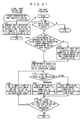
- FIG. 15 shows a flowchart of processing when a port selection switch is operated in a signal input device.
- the CPU 31 of the signal input device 30 Upon detecting the operation of the port selection switch 34, the CPU 31 of the signal input device 30 starts the processing in the flowchart at the left side of FIG. 15 . In this processing, the CPU 31 transfers control data indicating the fact that the switch is operated and a port number corresponding to the operated switch to the DAW application 20 of the PC 10 (S101).
- the control data complies with a protocol specified by a simple setting function being a setting function of a signal transmission path in the DAW application 20 to be described with reference to this flowchart. Further, if the device can transmit the control data, it indicates that the device supports the simple setting function of the DAW application 20.
- the CPU 61 of the PC 10 Upon receiving the control data, the CPU 61 of the PC 10 starts the processing in the flowchart at the right side of FIG. 15 .
- step S61 in FIG. 13 a setting of signal transmission path through which waveform data outputted from a port corresponding to the operated port selection switch 34 is supplied to an audio track being in the selected state. Accordingly, the CPU 61 first discriminates whether or not any audio track is in the selected state (S111), and if there is no track in the selected state, the processing is terminated.
- the CPU 61 first sets one of the tracks as a processing target (S112).
- a selection criterion for the processing target is that it has the smallest ID, or the like, and an arbitrary criterion can be applied.
- the first processing target is referred to in port selection processing in step S114, it is preferably highly recognizable to a user.
- the CPU 61 discriminates, based on the input bus data and the connection destination device data in FIG. 9 , whether or not the port corresponding to the operated switch of a device being a control data transmission source is connected to any input bus of the DAW application 20 via a reception port of the PC 10 (S113). If there is no connection, port connection processing shown in FIG. 16 is conducted in order to firstly connect the port and the bus (S114).
- the CPU 61 first decides a bus ID of a new bus to add the bus data to the input bus data in FIG. 9 and sets the number of channels Nc corresponding to a type of an audio track being the processing target, to thereby newly create an input bus of a type being the same type (monaural/stereo) as the audio track being the processing target (S131).
- the type of the created bus is matched to that of the audio track being the processing target on the ground that the created bus is for supplying waveform data to the track being the processing target.
- the CPU 61 instructs the device being the control data transmission source to set the port corresponding to the operated switch to be in a monaural mode in accordance with the type of the bus (S133).
- the signal input device 30 being the control data transmission source starts processing in a flowchart at the right side of FIG. 16 , sets the designated port to be in the monaural mode (S151), and returns a setting result to the DAW application 20 (S152). Note that even if the designated port is originally in a stereo mode and a stereo pair including the designated port is split and both ports are set to be in the monaural mode through the processing in step S151, when there is a connection between the port being the other of the pair and any bus, the connection can be maintained.
- the CPU 61 Upon receiving the response of the setting result, the CPU 61 connects the bus created in step S 131 to a reception port corresponding to the port set to be in the monaural mode (S134), and returns to the processing in FIG. 15 .
- the CPU 61 discriminates whether or not a port to be paired (stereo pair) with the port corresponding to the operated switch of the device being the control data transmission source is connected to any input bus (S135). If there is a connection, the CPU 61 displays a warning on the screen, and accepts an instruction from a user (S 136).
- FIG. 17 shows an example of this warning screen. On this screen, an instruction indicating force or cancel is accepted.
- the CPU 61 When the instruction of forcible connection is accepted (YES in S137), the CPU 61 releases the connection between the input bus and the port to be paired with the port corresponding to the operated switch (S138). Thereafter, the CPU 61 instructs the device being the control data transmission source to set the port corresponding to the operated switch and the port to be paired with the port to be in the stereo mode in accordance with the type of the bus (S139).
- the signal input device 30 being the control data transmission source starts processing in the flowchart at the right side of FIG. 16 , sets the designated ports being paired to be in the stereo mode (S161), and returns a setting result to the DAW application 20 (S162).
- the CPU 61 Upon receiving the response of the setting result, the CPU 61 connects the bus created in step S131 to reception ports corresponding to the ports set to be in the stereo mode (S140), and returns to the processing in FIG. 15 .
- step S135 there is no need to accept the instruction from the user, so that the processing proceeds directly to step S139.
- step S 113 When the connection between the port corresponding to the operated switch and the bus can be confirmed in step S 113 or the connection can be made in step S114, the processing proceeds to step S115.
- the bus (connection destination bus) connected to the port corresponding to the operated switch is connected to the track in the selective state.
- the CPU 61 first discriminates, based on the audio track data and the input bus data in FIG. 9 , whether or not the track being the processing target and the connection destination bus are of the same type (S115). Here, if they are of the same type, there is no problem, and thus the CPU 61 connects the audio track being the processing target to the connection destination bus (S116) by setting a bus ID of the connection destination bus on the input source bus ID of the data of the track being the processing target in FIG. 9 . Then, if there are audio tracks in the selected state which are not yet set as the processing target, one of the tracks is set as the next processing target (S120 and S121), and the processing from step S 115 is repeated.
- the CPU 61 displays a warning screen on the display, and accepts an instruction from a user.
- the bus is created in the port connection processing in FIG. 16 , there is no chance that the bus differs from the track in the type. However, if it becomes YES in step S113, the type may differ. Further, the warning screen differs depending on whether the track being the processing target is a stereo track or a monaural track.
- FIG. 18 shows a display example when the track is a stereo track.
- an instruction indicating connection or skip is accepted.
- the processing proceeds from steps S118 to S119, and the CPU 61 connects the audio track being the processing target to the connection destination bus. Note that even if the monaural bus is connected to the stereo track, the same signal is merely recorded in both channels of the track, and no particular problems occur.
- the instruction indicating skip is made, the track being the processing target at this time is not connected to the bus, and the processing proceeds to step S120.
- FIG. 19 shows a display example when the track is a monaural track.
- step S118 When the instruction indicating L connection or R connection is made on this screen, the processing proceeds from steps S118 to S119, and the CPU 61 connects audio track being the processing target to the connection destination bus in accordance with the instructed contents.
- the instruction indicating skip is made, the track is not connected to the bus and the processing proceeds to step S120, similar to the aforementioned case of monaural track.
- the CPU 31 serves as an operation contents transmitter in step S101. Further, the CPU 61 serves as a first setting device in a case of YES in step S113, and it serves as a second setting device in a case of NO in step S113.
- the aforementioned processing executed by the CPUs enables a user, by merely selecting a track to be used for recording and pressing a button corresponding to a port from which a signal is supplied to the track at the signal input device 30 side, to automatically set a transmission path transmitting the signal between the port and the track. Therefore, even when a virtual bus is used and a transmission path becomes complicated, it is possible to conduct a setting of the transmission path with simple operation.
- step S114 in FIG. 15 the port connection processing shown in FIG. 20 may be conducted instead of the port connection processing shown in FIG. 16 .
- the CPU 61 When this processing is performed, the CPU 61 first makes inquiries to the device being the control data transmission source about a mode of the port corresponding to the operated switch (S171). Subsequently, when a response to the inquiries is returned from the signal input device 30 being the control data transmission source (S181), the CPU 61 newly creates an input bus of a type (monaural/stereo) corresponding to the responded mode (S172). Thereafter, the CPU 61 connects the created bus to a reception port corresponding to the port corresponding to the operated switch (S173), and returns to the processing in FIG 15 . If the bus is a stereo bus, the bus is also connected to a reception port corresponding to a port to be paired with the port corresponding to the operated switch.
- the type of the newly created bus is decided based on the type of the track to be connected in the processing shown in FIG. 16 , but, it is decided based on the mode of the port of the connection destination in the processing in FIG. 20 .
- the processing in FIG. 20 is preferable since at least the connection between the port and the bus can be surely conducted.
- the processing in FIG. 16 is preferable.
- one reception port can be connected to only one bus in the aforementioned embodiment, it may be possible to connect one reception port to a plurality of buses, as another modification. Also in this case, it is possible to follow the arrow in the opposite direction along the transmission path shown in FIG. 5 , and by executing the processing described in the aforementioned embodiment in the same manner, the same effect can be obtained.
- one reception port can be connected to one bus for each type which can be used.
- An example of the above is that a port connected to a certain monaural bus can be connected to a stereo bus, although it cannot be connected to another monaural bus.
- first to eighth reception ports receiving waveform data from a certain device are respectively connected to first to eighth monaural buses, and two of the reception ports are sequentially paired from the low-numbered one, and connected to first to fourth stereo buses.
- connection form is applied, by appropriately connecting the bus and the track, it is possible to obtain almost the same effect as in the case where the connection relation between the port and the bus is freely discriminated, in terms of inputting waveform data outputted from a desired port of a signal input device into a desired track.
- connection relation between the port and the bus is fixed, even when a bus and a track which input multichannel surround audio such as 4-channel, 5.1-channel, 6.1-channel are provided, it is possible to easily manage the connection relation between the port and the bus.
- the processing shown in FIG. 21 may be executed instead of the processing shown in FIG. 15 .
- step S111 the processing at the signal input device 30 side and the processing in step S111 at the DAW application 20 side are performed in the same manner as in the case of FIG. 15 .
- the CPU 61 discriminates whether or not the port corresponding to the operated switch in the device being the control data transmission source is connected to the corresponding various input buses (both the monaural bus and the stereo bus, for instance) via reception ports of the PC 10 (S192). If the port is not connected to at least one type of the buses, the CPU 61 creates the unconnected corresponding input bus and connects the created bus to a reception port corresponding to the port corresponding to the operated switch (S193). At this time, there is no need to consider the mode of the port at the signal input device 30 side.
- the CPU 61 connects the track being the processing target to the bus of the same type which is connected to the port corresponding to the operated switch (S195 to S197).
- a configuration in which a bus and a track which input multichannel surround audio such as 4-channel, 5.1-channel, 6.1-channel can be formed, together with the configuration in which one reception port is connected to only one bus as described in the aforementioned embodiment. It is of course possible to form buses and tracks of three types or more. Also in the above cases, the processing described using FIG. 10 to FIG. 21 can be similarly applied.
- a monaural bus and a monaural track can be handled in the same manner, and a surround bus/track (stereo is also a kind of surround) can be handled in a manner similar to the case of the stereo bus according to the number of channels.
- step S19 or the like is for specifying the signal input device and its transmission port being supply sources of waveform data inputted into the track, and the search can be conducted also in a case where no bus is interposed between the track and the port.
- a lamp as an indicator corresponding to a port in the signal input device 30
- the display indicating the state of port can be performed not only by lighting-on, lighting-off or blinking the lamp, but also by using a lighting color of the lamp, a figure, a character or the like.
- controls or lamps do not have to physically exist independently and can be displayed on a screen using a touch panel and a display.
- the signal input device 30 outputs audio signals inputted from terminals through output ports corresponding to the respective terminals, in which a part of the audio signal outputted from the output port may be a reproduced signal previously recorded in a recording medium built in the device. Further, the correspondence between the terminal and the port does not always have to be one-to-one.
- the signal input device 30 may be an audio signal processing device such as a recorder, an effector, a synthesizer and a tone generator to which a waveform data transmitting function is provided.
- an audio signal processing device such as a recorder, an effector, a synthesizer and a tone generator to which a waveform data transmitting function is provided.
- a device such as a digital mixer configured using dedicated hardware as an audio signal processing device to which a function to perform control of lamps or to set signal transmission paths as described above is provided.
- a plurality of different models of signal input devices may be connected to the PC 10.
- An arbitrary transmission method between the signal input device and the audio signal processing device can be applied regardless of wire or wireless as long as a real time transmission of waveform data is possible.
- the program to cause a computer to function as an audio signal processing device and realize the above-described functions can be previously stored in a ROM, a HDD and the like or recorded in a nonvolatile recording medium (memory) such as a CD-ROM or a flexible disk and read to a RAM from the memory so that the CPU can execute the program.
- the program can be downloaded from an external device including a recording medium recording the program or an external device storing the program in its memory such as an HDD. The same effect can be obtained in any of the above method.
- the audio signal processing system or the computer readable medium of this invention even when audio signals transmitted from an external device are recorded in a plurality of tracks of an audio signal processing device, it is possible to easily recognize a correspondence between the tracks and the device being a signal supply source.
- an application of this invention provides an audio signal processing system with an improved operability.
Landscapes
- Engineering & Computer Science (AREA)
- Signal Processing (AREA)
- Circuit For Audible Band Transducer (AREA)
- Signal Processing Not Specific To The Method Of Recording And Reproducing (AREA)
Claims (6)
- Audiosignalverarbeitungssystem (1), aufweisend:eine Signaleingabevorrichtung (30), die mehrere Audiosignale von außerhalb empfängt und die mehreren Audiosignale über mehrere Sendeanschlüsse in der Signaleingabevorrichtung (30) an eine Audiosignalverarbeitungsvorrichtung (10) sendet; undeine Audiosignalverarbeitungsvorrichtung (10), aufweisend: mehrere Empfangsanschlüsse, von denen jeder ein von der Signaleingabevorrichtung (30) gesendetes Audiosignal empfängt; mehrere Busse (25), von denen jeder mit einem der mehreren Empfangsanschlüsse verbunden ist und das von dem einen Empfangsanschluss empfangene Audiosignal empfängt; und mehrere Spuren (27), von denen jede das von einem der mehreren Busse (25) gelieferte Audiosignal aufzeichnet,wobei die Signaleingabevorrichtung (30) ferner aufweist:Anzeigevorrichtungen (35), die den mehreren Sendeanschlüssen entsprechen; undeine Anzeigesteuerung, die die Anzeigevorrichtungen (35) gemäß von der Audiosignalverarbeitungsvorrichtung (10) empfangenen Steuerdaten steuert, undwobei die Audiosignalverarbeitungsvorrichtung (10) ferner aufweist:einen Speicher (63), in dem Daten abgelegt sind, die hinsichtlich eines jeden der mehreren Busse (25) einen der mehreren Empfangsanschlüsse, mit dem der eine Bus (25) verbunden ist, und einen Sendeanschluss der Eingabevorrichtung (30) angeben, über den ein von dem einen Empfangsanschluss empfangenes Audiosignal von der Eingabevorrichtung (30) gesendet wird;eine Auswahlvorrichtung, die gemäß einer Bedienung durch einen Benutzer eine der mehreren Spuren (27) auswählt (S61);eine Suchvorrichtung, die, wenn die Auswahlvorrichtung eine Spur (27) auswählt, einen Bus (25) sucht, der das Audiosignal an die ausgewählte Spur liefert (S62); undeinen Steuerungsdatensender, der, wenn die Suchvorrichtung einen Bus (25) findet, der das Audiosignal an die ausgewählte Spur (27) liefert, feststellt, ob ein mit dem gefundenen Bus (25) verbundener Empfangsanschluss ein über einen Sendeanschluss der Signaleingabevorrichtung (30) gesendetes Audiosignal empfängt oder nicht, und zwar auf der Grundlage der in dem Speicher (63) abgelegten Daten, und wenn die Feststellung positiv ausfällt, an die Signaleingabevorrichtung (30) erste Steuerungsdaten sendet, welche die Anzeigesteuerung in der Signaleingabevorrichtung anweisen, eine der Anzeigevorrichtungen (35), die dem einen Sendeanschluss entspricht, so zu steuern, dass angezeigt wird, dass der eine Sendeanschluss mit der ausgewählten Spur verbunden ist (S64).
- Audiosignalverarbeitungssystem (1) gemäß Anspruch 1,
wobei die Audiosignalverarbeitungsvorrichtung (10) ferner aufweist:eine Ladevorrichtung, die Projektdaten liest, die Daten über Spuren (27) und Einstellungsdaten von Empfangsanschlüssen und Bussen (25) enthalten, und die auf der Grundlage der gelesenen Projektdaten die Spuren (27), die Empfangsanschlüsse und die Busse (25) vorbereitet, die die Spuren (27) und die Empfangsanschlüsse verbinden (S11 bis S15);eine zweite Suchvorrichtung, die, wenn die Ladevorrichtung die Spuren (27), die Empfangsanschlüsse und die Busse (25) vorbereitet, nach Bussen (25) sucht, die Audiosignale an die vorbereiteten Spuren liefern (S19); undeinen zweiten Steuerungsdatensender, der, wenn die zweite Suchvorrichtung einen oder mehrere Busse (25) findet, feststellt, ob einer oder mehrere mit den gefundenen Bussen (25) verbundene Empfangsanschlüsse eines oder mehrere Audiosignale empfangen, die über einen oder mehrere Sendeanschlüsse der Signaleingabevorrichtung (30) gesendet werden, oder nicht, und zwar auf der Grundlage der in dem Speicher (63) abgelegten Daten, und wenn die Feststellung positiv ausfällt, an die Signaleingabevorrichtung (30) zweite Steuerungsdaten sendet, welche die Anzeigesteuerung in der Signaleingabevorrichtung (30) anweisen, eine oder mehrere Anzeigevorrichtungen (35), die dem einen oder den mehreren Sendeanschlüssen entsprechen, so zu steuern, dass angezeigt wird, dass der eine oder die mehreren Sendeanschlüsse mit den vorbereiteten Spuren verbunden sind (S21). - Audiosignalverarbeitungssystem (1) gemäß Anspruch 1 oder 2,
wobei die Audiosignalverarbeitungsvorrichtung (10) ferner aufweist:eine Änderungsvorrichtung, die eine Audiosignal-Lieferquelle für eine Spur (27) gemäß einer Benutzerbedienung von einem Bus (25) in einen anderen Bus (25) ändert, indem eine Lieferung eines Audiosignals von dem einen der Busse (25) an die Spur (27) gestoppt wird und eine Lieferung eines Audiosignals von dem anderen Bus (25) an die Spur begonnen wird (S81); undeinen dritten Steuerungsdatensender, der in Reaktion auf die Änderung der Audiosignal-Lieferquelle für die Spur (27) durch die Änderungsvorrichtung a) auf der Grundlage der in dem Speicher (63) abgelegten Daten feststellt, ob der eine Bus (25) mit einem Empfangsanschluss verbunden ist, der ein über einen ersten Sendeanschluss der Signaleingabevorrichtung (30) gesendetes Audiosignal empfängt, oder nicht, und ob der eine Bus (25) nach der Änderung das Audiosignal nicht länger an eine der mehreren Spuren (27) liefert oder nicht, und wenn beide Feststellungen positiv ausfallen, an die Signaleingabevorrichtung (30) dritte Steuerungsdaten sendet, welche die Anzeigesteuerung in der Signaleingabevorrichtung (30) anweist, eine der Anzeigevorrichtungen (35), die dem ersten Sendeanschluss entspricht, so zu steuern, dass angezeigt wird, dass der erste Sendanschluss mit keiner der Spuren mehr verbunden ist (S85), und b) auf der Grundlage der in dem Speicher (63) abgelegten Daten feststellt, ob der andere Bus (25) mit einem Empfangsanschluss verbunden ist, der ein über einen zweiten Sendanschluss des Signaleingabevorrichtung (30) gesendetes Audiosignal empfängt, oder nicht, und wenn die Feststellung positiv ausfällt, an die Eingabevorrichtung (30) vierte Steuerungsdaten sendet, welche die Anzeigesteuerung in der Signaleingabevorrichtung (30) anweisen, eine der Anzeigevorrichtungen (35), die dem zweiten Sendeanschluss entspricht, so zu steuern, dass angezeigt wird, dass der zweite Sendeanschluss neu mit der Spur verbunden ist (S88). - Maschinenlesbares Medium, das Programmbefehle enthält, die von einem Computer ausführbar sind und den Computer dazu veranlassen, zu fungieren als:mehrere Empfangsanschlüsse, von denen jeder ein Audiosignal empfängt, das von einer Signaleingabevorrichtung (30) gesendet wird;mehrere Busse (25), von denen jeder mit einem der mehreren Empfangsanschlüsse verbunden ist und das von dem einen Empfangsanschluss empfangene Audiosignal empfängt;mehrere Spuren (27), von denen jede das von dem einen der mehreren Busse (25) gelieferte Audiosignal aufzeichnet,einen Speicher (63), in dem Daten abgelegt sind, die hinsichtlich eines jeden der mehreren Busse (25) einen der mehreren Empfangsanschlüsse, mit dem der eine Bus (25) verbunden ist, und einen Sendeanschluss der Eingabevorrichtung (30) angeben, über den ein von dem einen Empfangsanschluss empfangenes Audiosignal von der Eingabevorrichtung (30) gesendet wird;eine Auswahlvorrichtung, die gemäß einer Bedienung durch einen Benutzer eine der mehreren Spuren (27) auswählt;eine Suchvorrichtung, die, wenn die Auswahlvorrichtung eine Spur (27) auswählt, einen Bus (25) sucht, der das Audiosignal an die ausgewählte Spur (27) liefert; undeinen Steuerungsdatensender, der, wenn die Suchvorrichtung einen Bus (25) findet, der das Audiosignal an die ausgewählte Spur (27) liefert, feststellt, ob ein mit dem gefundenen Bus (25) verbundener Empfangsanschluss ein über einen Sendeanschluss der Signaleingabevorrichtung (30) gesendetes Audiosignal empfängt oder nicht, und zwar auf der Grundlage der in dem Speicher (63) abgelegten Daten, und wenn die Feststellung positiv ausfällt, an die Signaleingabevorrichtung (30) erste Steuerungsdaten sendet, welche eine Anzeigesteuerung in der Signaleingabevorrichtung anweisen, eine Anzeigevorrichtung (35), die dem einen Sendeanschluss entspricht, so zu steuern, dass angezeigt wird, dass der eine Sendeanschluss mit der ausgewählten Spur verbunden ist (S64).
- Maschinenlesbares Medium gemäß Anspruch 4, ferner enthaltend Programmbefehle, die von einem Computer ausführbar sind und den Computer dazu veranlassen, zu fungieren als:eine Ladevorrichtung, die Projektdaten liest, die Daten über Spuren (27) und Einstellungsdaten von Empfangsanschlüssen und Bussen (25) enthalten, und die auf der Grundlage der gelesenen Projektdaten die Spuren (27), die Empfangsanschlüsse und die Busse (25) vorbereitet, die die Spuren (27) und die Empfangsanschlüsse verbinden (S11 bis S15);eine zweite Suchvorrichtung, die, wenn die Ladevorrichtung die Spuren (27), die Empfangsanschlüsse und die Busse (25) vorbereitet, nach Bussen (25) sucht, die Audiosignale an die vorbereiteten Spuren liefern (S19); undeinen zweiten Steuerungsdatensender, der, wenn die zweite Suchvorrichtung einen oder mehrere Busse (25) findet, feststellt, ob einer oder mehrere mit den gefundenen Bussen (25) verbundene Empfangsanschlüsse eines oder mehrere Audiosignale empfangen, die über einen oder mehrere Sendeanschlüsse der Signaleingabevorrichtung (30) gesendet werden, oder nicht, und zwar auf der Grundlage der in dem Speicher (63) abgelegten Daten, und wenn die Feststellung positiv ausfällt, an die Signaleingabevorrichtung (30) zweite Steuerungsdaten sendet, welche die Anzeigesteuerung in der Signaleingabevorrichtung (30) anweisen, eine oder mehrere Anzeigevorrichtungen (35), die dem einen oder den mehreren Sendeanschlüssen entsprechen, so zu steuern, dass angezeigt wird, dass der eine oder die mehreren Sendeanschlüsse mit den vorbereiteten Spuren verbunden sind (S21).
- Maschinenlesbares Medium gemäß Anspruch 4 oder 5, ferner enthaltend Programmbefehle, die von einem Computer ausführbar sind und den Computer dazu veranlassen, zu fungieren als:eine Änderungsvorrichtung, die eine Audiosignal-Lieferquelle für eine Spur (27) gemäß einer Benutzerbedienung von einem Bus (25) in einen anderen Bus (25) ändert, indem eine Lieferung eines Audiosignals von dem einen Bus (25) an die Spur gestoppt wird und eine Lieferung eines Audiosignals von dem anderen Bus (25) an die Spur begonnen wird (S81); undeinen dritten Steuerungsdatensender, der in Reaktion auf die Änderung der Audiosignal-Lieferquelle für die Spur (27) durch die Änderungsvorrichtung a) auf der Grundlage der in dem Speicher (63) abgelegten Daten feststellt, ob der eine Bus (25) mit einem Empfangsanschluss verbunden ist, der ein über einen ersten Sendeanschluss der Signaleingabevorrichtung (30) gesendetes Audiosignal empfängt, oder nicht, und ob der eine Bus (25) nach der Änderung das Audiosignal nicht länger an eine der mehreren Spuren (27) liefert oder nicht, und wenn beide Feststellungen positiv ausfallen, an die Signaleingabevorrichtung. (30) dritte Steuerungsdaten sendet, welche die Anzeigesteuerung in der Signaleingabevorrichtung (30) anweist, eine der Anzeigevorrichtungen (35), die dem ersten Sendeanschluss entspricht, so zu steuern, dass angezeigt wird, dass der erste Sendanschluss mit keiner der Spuren mehr verbunden ist (S85), und b) auf der Grundlage der in dem Speicher (63) abgelegten Daten feststellt, ob der andere Bus (25) mit einem Empfangsanschluss verbunden ist, der ein über einen zweiten Sendanschluss des Signaleingabevorrichtung (30) gesendetes Audiosignal empfängt, oder nicht, und wenn die Feststellung positiv ausfällt, an die Eingabevorrichtung (30) vierte Steuerungsdaten sendet, welche die Anzeigesteuerung in der Signaleingabevorrichtung (30) anweisen, eine der Anzeigevorrichtungen, die dem zweiten Sendeanschluss entspricht, so zu steuern, dass angezeigt wird, dass der zweite Sendeanschluss neu mit der Spur verbunden ist (S88).
Priority Applications (1)
| Application Number | Priority Date | Filing Date | Title |
|---|---|---|---|
| EP13152825.9A EP2587697B1 (de) | 2008-03-11 | 2009-03-11 | Audiosignalverarbeitungssystem |
Applications Claiming Priority (2)
| Application Number | Priority Date | Filing Date | Title |
|---|---|---|---|
| JP2008061918A JP5206038B2 (ja) | 2008-03-11 | 2008-03-11 | 音響信号処理システム及びプログラム |
| JP2008061917A JP5098713B2 (ja) | 2008-03-11 | 2008-03-11 | 音響信号処理システム及びプログラム |
Related Child Applications (2)
| Application Number | Title | Priority Date | Filing Date |
|---|---|---|---|
| EP13152825.9A Division EP2587697B1 (de) | 2008-03-11 | 2009-03-11 | Audiosignalverarbeitungssystem |
| EP13152825.9A Division-Into EP2587697B1 (de) | 2008-03-11 | 2009-03-11 | Audiosignalverarbeitungssystem |
Publications (3)
| Publication Number | Publication Date |
|---|---|
| EP2129015A2 EP2129015A2 (de) | 2009-12-02 |
| EP2129015A3 EP2129015A3 (de) | 2012-09-26 |
| EP2129015B1 true EP2129015B1 (de) | 2014-02-26 |
Family
ID=41058564
Family Applications (2)
| Application Number | Title | Priority Date | Filing Date |
|---|---|---|---|
| EP13152825.9A Not-in-force EP2587697B1 (de) | 2008-03-11 | 2009-03-11 | Audiosignalverarbeitungssystem |
| EP20090154847 Not-in-force EP2129015B1 (de) | 2008-03-11 | 2009-03-11 | Audiosignalverarbeitungssystem |
Family Applications Before (1)
| Application Number | Title | Priority Date | Filing Date |
|---|---|---|---|
| EP13152825.9A Not-in-force EP2587697B1 (de) | 2008-03-11 | 2009-03-11 | Audiosignalverarbeitungssystem |
Country Status (2)
| Country | Link |
|---|---|
| US (2) | US8301280B2 (de) |
| EP (2) | EP2587697B1 (de) |
Families Citing this family (9)
| Publication number | Priority date | Publication date | Assignee | Title |
|---|---|---|---|---|
| US8301280B2 (en) | 2008-03-11 | 2012-10-30 | Yamaha Corporation | Audio signal processing system |
| JP5682508B2 (ja) * | 2011-08-29 | 2015-03-11 | ヤマハ株式会社 | ミキシングシステム |
| JP6056195B2 (ja) * | 2012-05-24 | 2017-01-11 | ヤマハ株式会社 | 音響信号処理装置 |
| JP6102123B2 (ja) * | 2012-08-24 | 2017-03-29 | ティアック株式会社 | マルチトラックレコーダ |
| US20140107820A1 (en) * | 2012-10-16 | 2014-04-17 | Shih-Yao Chen | Audio Equipment and Wireless Electronic Device Combination System |
| US10127912B2 (en) | 2012-12-10 | 2018-11-13 | Nokia Technologies Oy | Orientation based microphone selection apparatus |
| JP2015188203A (ja) * | 2014-03-11 | 2015-10-29 | ヤマハ株式会社 | 音響システムおよび音響信号処理装置 |
| JP6926558B2 (ja) | 2017-03-17 | 2021-08-25 | ヤマハ株式会社 | データ処理ユニット及び情報処理装置 |
| JP7147599B2 (ja) * | 2019-01-30 | 2022-10-05 | ヤマハ株式会社 | 音信号処理装置、音響システム、音信号処理方法およびプログラム |
Family Cites Families (3)
| Publication number | Priority date | Publication date | Assignee | Title |
|---|---|---|---|---|
| US7565212B2 (en) * | 2001-06-13 | 2009-07-21 | Yamaha Corporation | Configuration method of digital audio mixer |
| JP4924019B2 (ja) | 2006-12-27 | 2012-04-25 | ヤマハ株式会社 | 音響信号処理システム |
| US8301280B2 (en) | 2008-03-11 | 2012-10-30 | Yamaha Corporation | Audio signal processing system |
-
2009
- 2009-03-10 US US12/401,557 patent/US8301280B2/en active Active
- 2009-03-11 EP EP13152825.9A patent/EP2587697B1/de not_active Not-in-force
- 2009-03-11 EP EP20090154847 patent/EP2129015B1/de not_active Not-in-force
-
2012
- 2012-05-04 US US13/464,935 patent/US8914138B2/en active Active
Also Published As
| Publication number | Publication date |
|---|---|
| EP2587697B1 (de) | 2015-01-14 |
| US8301280B2 (en) | 2012-10-30 |
| US8914138B2 (en) | 2014-12-16 |
| US20120221132A1 (en) | 2012-08-30 |
| US20090234477A1 (en) | 2009-09-17 |
| EP2129015A2 (de) | 2009-12-02 |
| EP2129015A3 (de) | 2012-09-26 |
| EP2587697A1 (de) | 2013-05-01 |
Similar Documents
| Publication | Publication Date | Title |
|---|---|---|
| EP2129015B1 (de) | Audiosignalverarbeitungssystem | |
| EP1939857B1 (de) | Audiosignalverarbeitungssystem | |
| CN101046953B (zh) | 音乐处理设备及其管理方法 | |
| US8935444B2 (en) | Remote control method of external devices | |
| JP5098713B2 (ja) | 音響信号処理システム及びプログラム | |
| JP2007293312A (ja) | 音楽処理装置 | |
| EP1939856B1 (de) | Audiosignalverarbeitungssystem | |
| JP4362768B2 (ja) | 外部機器の制御方法、外部機器の制御装置およびプログラム | |
| US7414634B2 (en) | Audio signal processing system | |
| JP5206038B2 (ja) | 音響信号処理システム及びプログラム | |
| JP4823483B2 (ja) | 外部機器の制御方法、外部機器の制御装置およびプログラム | |
| JP4924020B2 (ja) | 音響信号処理システム | |
| CN111506290B (zh) | 声音信号处理装置、声音信号处理方法及存储有程序的存储介质 | |
| US8214502B2 (en) | Communication path setup apparatus, communication path setup program, and storage medium storing the program | |
| JP4957324B2 (ja) | 音楽処理装置 | |
| JP4823482B2 (ja) | 外部機器の制御方法、外部機器の制御装置およびプログラム | |
| JP5152152B2 (ja) | リモート制御システムおよびリモート制御方法 | |
| JP5152151B2 (ja) | リモート制御システムおよびリモート制御方法 | |
| JP3925110B2 (ja) | 音声信号編集装置の制御方法、音声信号編集装置およびプログラム | |
| JP2004030373A (ja) | 信号処理装置及び該装置の制御プログラム |
Legal Events
| Date | Code | Title | Description |
|---|---|---|---|
| PUAI | Public reference made under article 153(3) epc to a published international application that has entered the european phase |
Free format text: ORIGINAL CODE: 0009012 |
|
| AK | Designated contracting states |
Kind code of ref document: A2 Designated state(s): AT BE BG CH CY CZ DE DK EE ES FI FR GB GR HR HU IE IS IT LI LT LU LV MC MK MT NL NO PL PT RO SE SI SK TR |
|
| AX | Request for extension of the european patent |
Extension state: AL BA RS |
|
| PUAL | Search report despatched |
Free format text: ORIGINAL CODE: 0009013 |
|
| RIC1 | Information provided on ipc code assigned before grant |
Ipc: H04H 60/04 20080101AFI20120730BHEP |
|
| RIC1 | Information provided on ipc code assigned before grant |
Ipc: H04H 60/04 20080101AFI20120807BHEP |
|
| RIC1 | Information provided on ipc code assigned before grant |
Ipc: H04H 60/04 20080101AFI20120816BHEP |
|
| AK | Designated contracting states |
Kind code of ref document: A3 Designated state(s): AT BE BG CH CY CZ DE DK EE ES FI FR GB GR HR HU IE IS IT LI LT LU LV MC MK MT NL NO PL PT RO SE SI SK TR |
|
| AX | Request for extension of the european patent |
Extension state: AL BA RS |
|
| 17P | Request for examination filed |
Effective date: 20130325 |
|
| AKX | Designation fees paid |
Designated state(s): AT BE BG CH CY CZ DE DK EE ES FI FR GB GR HR HU IE IS IT LI LT LU LV MC MK MT NL NO PL PT RO SE SI SK TR |
|
| GRAP | Despatch of communication of intention to grant a patent |
Free format text: ORIGINAL CODE: EPIDOSNIGR1 |
|
| INTG | Intention to grant announced |
Effective date: 20130910 |
|
| GRAS | Grant fee paid |
Free format text: ORIGINAL CODE: EPIDOSNIGR3 |
|
| GRAA | (expected) grant |
Free format text: ORIGINAL CODE: 0009210 |
|
| AK | Designated contracting states |
Kind code of ref document: B1 Designated state(s): AT BE BG CH CY CZ DE DK EE ES FI FR GB GR HR HU IE IS IT LI LT LU LV MC MK MT NL NO PL PT RO SE SI SK TR |
|
| REG | Reference to a national code |
Ref country code: GB Ref legal event code: FG4D |
|
| REG | Reference to a national code |
Ref country code: CH Ref legal event code: EP |
|
| REG | Reference to a national code |
Ref country code: AT Ref legal event code: REF Ref document number: 654114 Country of ref document: AT Kind code of ref document: T Effective date: 20140315 |
|
| REG | Reference to a national code |
Ref country code: IE Ref legal event code: FG4D |
|
| REG | Reference to a national code |
Ref country code: DE Ref legal event code: R096 Ref document number: 602009021961 Country of ref document: DE Effective date: 20140410 |
|
| REG | Reference to a national code |
Ref country code: NL Ref legal event code: VDEP Effective date: 20140226 |
|
| REG | Reference to a national code |
Ref country code: AT Ref legal event code: MK05 Ref document number: 654114 Country of ref document: AT Kind code of ref document: T Effective date: 20140226 |
|
| REG | Reference to a national code |
Ref country code: LT Ref legal event code: MG4D |
|
| PG25 | Lapsed in a contracting state [announced via postgrant information from national office to epo] |
Ref country code: NO Free format text: LAPSE BECAUSE OF FAILURE TO SUBMIT A TRANSLATION OF THE DESCRIPTION OR TO PAY THE FEE WITHIN THE PRESCRIBED TIME-LIMIT Effective date: 20140526 Ref country code: LT Free format text: LAPSE BECAUSE OF FAILURE TO SUBMIT A TRANSLATION OF THE DESCRIPTION OR TO PAY THE FEE WITHIN THE PRESCRIBED TIME-LIMIT Effective date: 20140226 Ref country code: IS Free format text: LAPSE BECAUSE OF FAILURE TO SUBMIT A TRANSLATION OF THE DESCRIPTION OR TO PAY THE FEE WITHIN THE PRESCRIBED TIME-LIMIT Effective date: 20140626 |
|
| PG25 | Lapsed in a contracting state [announced via postgrant information from national office to epo] |
Ref country code: PT Free format text: LAPSE BECAUSE OF FAILURE TO SUBMIT A TRANSLATION OF THE DESCRIPTION OR TO PAY THE FEE WITHIN THE PRESCRIBED TIME-LIMIT Effective date: 20140626 Ref country code: AT Free format text: LAPSE BECAUSE OF FAILURE TO SUBMIT A TRANSLATION OF THE DESCRIPTION OR TO PAY THE FEE WITHIN THE PRESCRIBED TIME-LIMIT Effective date: 20140226 Ref country code: CY Free format text: LAPSE BECAUSE OF FAILURE TO SUBMIT A TRANSLATION OF THE DESCRIPTION OR TO PAY THE FEE WITHIN THE PRESCRIBED TIME-LIMIT Effective date: 20140226 Ref country code: FI Free format text: LAPSE BECAUSE OF FAILURE TO SUBMIT A TRANSLATION OF THE DESCRIPTION OR TO PAY THE FEE WITHIN THE PRESCRIBED TIME-LIMIT Effective date: 20140226 Ref country code: NL Free format text: LAPSE BECAUSE OF FAILURE TO SUBMIT A TRANSLATION OF THE DESCRIPTION OR TO PAY THE FEE WITHIN THE PRESCRIBED TIME-LIMIT Effective date: 20140226 Ref country code: SE Free format text: LAPSE BECAUSE OF FAILURE TO SUBMIT A TRANSLATION OF THE DESCRIPTION OR TO PAY THE FEE WITHIN THE PRESCRIBED TIME-LIMIT Effective date: 20140226 |
|
| PG25 | Lapsed in a contracting state [announced via postgrant information from national office to epo] |
Ref country code: BE Free format text: LAPSE BECAUSE OF FAILURE TO SUBMIT A TRANSLATION OF THE DESCRIPTION OR TO PAY THE FEE WITHIN THE PRESCRIBED TIME-LIMIT Effective date: 20140226 Ref country code: LV Free format text: LAPSE BECAUSE OF FAILURE TO SUBMIT A TRANSLATION OF THE DESCRIPTION OR TO PAY THE FEE WITHIN THE PRESCRIBED TIME-LIMIT Effective date: 20140226 Ref country code: HR Free format text: LAPSE BECAUSE OF FAILURE TO SUBMIT A TRANSLATION OF THE DESCRIPTION OR TO PAY THE FEE WITHIN THE PRESCRIBED TIME-LIMIT Effective date: 20140226 |
|
| PG25 | Lapsed in a contracting state [announced via postgrant information from national office to epo] |
Ref country code: CZ Free format text: LAPSE BECAUSE OF FAILURE TO SUBMIT A TRANSLATION OF THE DESCRIPTION OR TO PAY THE FEE WITHIN THE PRESCRIBED TIME-LIMIT Effective date: 20140226 Ref country code: DK Free format text: LAPSE BECAUSE OF FAILURE TO SUBMIT A TRANSLATION OF THE DESCRIPTION OR TO PAY THE FEE WITHIN THE PRESCRIBED TIME-LIMIT Effective date: 20140226 Ref country code: RO Free format text: LAPSE BECAUSE OF FAILURE TO SUBMIT A TRANSLATION OF THE DESCRIPTION OR TO PAY THE FEE WITHIN THE PRESCRIBED TIME-LIMIT Effective date: 20140226 Ref country code: EE Free format text: LAPSE BECAUSE OF FAILURE TO SUBMIT A TRANSLATION OF THE DESCRIPTION OR TO PAY THE FEE WITHIN THE PRESCRIBED TIME-LIMIT Effective date: 20140226 |
|
| REG | Reference to a national code |
Ref country code: CH Ref legal event code: PL |
|
| REG | Reference to a national code |
Ref country code: DE Ref legal event code: R097 Ref document number: 602009021961 Country of ref document: DE |
|
| PG25 | Lapsed in a contracting state [announced via postgrant information from national office to epo] |
Ref country code: SK Free format text: LAPSE BECAUSE OF FAILURE TO SUBMIT A TRANSLATION OF THE DESCRIPTION OR TO PAY THE FEE WITHIN THE PRESCRIBED TIME-LIMIT Effective date: 20140226 Ref country code: PL Free format text: LAPSE BECAUSE OF FAILURE TO SUBMIT A TRANSLATION OF THE DESCRIPTION OR TO PAY THE FEE WITHIN THE PRESCRIBED TIME-LIMIT Effective date: 20140226 Ref country code: MC Free format text: LAPSE BECAUSE OF FAILURE TO SUBMIT A TRANSLATION OF THE DESCRIPTION OR TO PAY THE FEE WITHIN THE PRESCRIBED TIME-LIMIT Effective date: 20140226 Ref country code: ES Free format text: LAPSE BECAUSE OF FAILURE TO SUBMIT A TRANSLATION OF THE DESCRIPTION OR TO PAY THE FEE WITHIN THE PRESCRIBED TIME-LIMIT Effective date: 20140226 |
|
| REG | Reference to a national code |
Ref country code: IE Ref legal event code: MM4A |
|
| PLBE | No opposition filed within time limit |
Free format text: ORIGINAL CODE: 0009261 |
|
| STAA | Information on the status of an ep patent application or granted ep patent |
Free format text: STATUS: NO OPPOSITION FILED WITHIN TIME LIMIT |
|
| PG25 | Lapsed in a contracting state [announced via postgrant information from national office to epo] |
Ref country code: CH Free format text: LAPSE BECAUSE OF NON-PAYMENT OF DUE FEES Effective date: 20140331 Ref country code: IE Free format text: LAPSE BECAUSE OF NON-PAYMENT OF DUE FEES Effective date: 20140311 Ref country code: LI Free format text: LAPSE BECAUSE OF NON-PAYMENT OF DUE FEES Effective date: 20140331 |
|
| 26N | No opposition filed |
Effective date: 20141127 |
|
| REG | Reference to a national code |
Ref country code: FR Ref legal event code: PLFP Year of fee payment: 7 |
|
| REG | Reference to a national code |
Ref country code: DE Ref legal event code: R097 Ref document number: 602009021961 Country of ref document: DE Effective date: 20141127 |
|
| PG25 | Lapsed in a contracting state [announced via postgrant information from national office to epo] |
Ref country code: IT Free format text: LAPSE BECAUSE OF FAILURE TO SUBMIT A TRANSLATION OF THE DESCRIPTION OR TO PAY THE FEE WITHIN THE PRESCRIBED TIME-LIMIT Effective date: 20140226 |
|
| PGFP | Annual fee paid to national office [announced via postgrant information from national office to epo] |
Ref country code: DE Payment date: 20150305 Year of fee payment: 7 |
|
| PG25 | Lapsed in a contracting state [announced via postgrant information from national office to epo] |
Ref country code: SI Free format text: LAPSE BECAUSE OF FAILURE TO SUBMIT A TRANSLATION OF THE DESCRIPTION OR TO PAY THE FEE WITHIN THE PRESCRIBED TIME-LIMIT Effective date: 20140226 |
|
| PGFP | Annual fee paid to national office [announced via postgrant information from national office to epo] |
Ref country code: GB Payment date: 20150311 Year of fee payment: 7 Ref country code: FR Payment date: 20150309 Year of fee payment: 7 |
|
| PG25 | Lapsed in a contracting state [announced via postgrant information from national office to epo] |
Ref country code: MT Free format text: LAPSE BECAUSE OF FAILURE TO SUBMIT A TRANSLATION OF THE DESCRIPTION OR TO PAY THE FEE WITHIN THE PRESCRIBED TIME-LIMIT Effective date: 20140226 |
|
| PG25 | Lapsed in a contracting state [announced via postgrant information from national office to epo] |
Ref country code: BG Free format text: LAPSE BECAUSE OF FAILURE TO SUBMIT A TRANSLATION OF THE DESCRIPTION OR TO PAY THE FEE WITHIN THE PRESCRIBED TIME-LIMIT Effective date: 20140226 Ref country code: GR Free format text: LAPSE BECAUSE OF FAILURE TO SUBMIT A TRANSLATION OF THE DESCRIPTION OR TO PAY THE FEE WITHIN THE PRESCRIBED TIME-LIMIT Effective date: 20140527 |
|
| PG25 | Lapsed in a contracting state [announced via postgrant information from national office to epo] |
Ref country code: LU Free format text: LAPSE BECAUSE OF NON-PAYMENT OF DUE FEES Effective date: 20140311 Ref country code: TR Free format text: LAPSE BECAUSE OF FAILURE TO SUBMIT A TRANSLATION OF THE DESCRIPTION OR TO PAY THE FEE WITHIN THE PRESCRIBED TIME-LIMIT Effective date: 20140226 Ref country code: HU Free format text: LAPSE BECAUSE OF FAILURE TO SUBMIT A TRANSLATION OF THE DESCRIPTION OR TO PAY THE FEE WITHIN THE PRESCRIBED TIME-LIMIT; INVALID AB INITIO Effective date: 20090311 |
|
| REG | Reference to a national code |
Ref country code: DE Ref legal event code: R119 Ref document number: 602009021961 Country of ref document: DE |
|
| GBPC | Gb: european patent ceased through non-payment of renewal fee |
Effective date: 20160311 |
|
| REG | Reference to a national code |
Ref country code: FR Ref legal event code: ST Effective date: 20161130 |
|
| PG25 | Lapsed in a contracting state [announced via postgrant information from national office to epo] |
Ref country code: GB Free format text: LAPSE BECAUSE OF NON-PAYMENT OF DUE FEES Effective date: 20160311 Ref country code: DE Free format text: LAPSE BECAUSE OF NON-PAYMENT OF DUE FEES Effective date: 20161001 Ref country code: FR Free format text: LAPSE BECAUSE OF NON-PAYMENT OF DUE FEES Effective date: 20160331 |
|
| PG25 | Lapsed in a contracting state [announced via postgrant information from national office to epo] |
Ref country code: MK Free format text: LAPSE BECAUSE OF FAILURE TO SUBMIT A TRANSLATION OF THE DESCRIPTION OR TO PAY THE FEE WITHIN THE PRESCRIBED TIME-LIMIT Effective date: 20140226 |