US10127912B2 - Orientation based microphone selection apparatus - Google Patents
Orientation based microphone selection apparatus Download PDFInfo
- Publication number
- US10127912B2 US10127912B2 US14/649,013 US201214649013A US10127912B2 US 10127912 B2 US10127912 B2 US 10127912B2 US 201214649013 A US201214649013 A US 201214649013A US 10127912 B2 US10127912 B2 US 10127912B2
- Authority
- US
- United States
- Prior art keywords
- audio
- microphones
- processor
- instance
- audio signals
- Prior art date
- Legal status (The legal status is an assumption and is not a legal conclusion. Google has not performed a legal analysis and makes no representation as to the accuracy of the status listed.)
- Active
Links
Images


Classifications
-
- G—PHYSICS
- G10—MUSICAL INSTRUMENTS; ACOUSTICS
- G10L—SPEECH ANALYSIS OR SYNTHESIS; SPEECH RECOGNITION; SPEECH OR VOICE PROCESSING; SPEECH OR AUDIO CODING OR DECODING
- G10L19/00—Speech or audio signals analysis-synthesis techniques for redundancy reduction, e.g. in vocoders; Coding or decoding of speech or audio signals, using source filter models or psychoacoustic analysis
-
- H—ELECTRICITY
- H04—ELECTRIC COMMUNICATION TECHNIQUE
- H04R—LOUDSPEAKERS, MICROPHONES, GRAMOPHONE PICK-UPS OR LIKE ACOUSTIC ELECTROMECHANICAL TRANSDUCERS; DEAF-AID SETS; PUBLIC ADDRESS SYSTEMS
- H04R5/00—Stereophonic arrangements
- H04R5/027—Spatial or constructional arrangements of microphones, e.g. in dummy heads
-
- H—ELECTRICITY
- H04—ELECTRIC COMMUNICATION TECHNIQUE
- H04S—STEREOPHONIC SYSTEMS
- H04S7/00—Indicating arrangements; Control arrangements, e.g. balance control
- H04S7/30—Control circuits for electronic adaptation of the sound field
-
- H—ELECTRICITY
- H04—ELECTRIC COMMUNICATION TECHNIQUE
- H04S—STEREOPHONIC SYSTEMS
- H04S7/00—Indicating arrangements; Control arrangements, e.g. balance control
- H04S7/40—Visual indication of stereophonic sound image
-
- H—ELECTRICITY
- H04—ELECTRIC COMMUNICATION TECHNIQUE
- H04R—LOUDSPEAKERS, MICROPHONES, GRAMOPHONE PICK-UPS OR LIKE ACOUSTIC ELECTROMECHANICAL TRANSDUCERS; DEAF-AID SETS; PUBLIC ADDRESS SYSTEMS
- H04R1/00—Details of transducers, loudspeakers or microphones
- H04R1/20—Arrangements for obtaining desired frequency or directional characteristics
- H04R1/32—Arrangements for obtaining desired frequency or directional characteristics for obtaining desired directional characteristic only
- H04R1/40—Arrangements for obtaining desired frequency or directional characteristics for obtaining desired directional characteristic only by combining a number of identical transducers
- H04R1/406—Arrangements for obtaining desired frequency or directional characteristics for obtaining desired directional characteristic only by combining a number of identical transducers microphones
-
- H—ELECTRICITY
- H04—ELECTRIC COMMUNICATION TECHNIQUE
- H04R—LOUDSPEAKERS, MICROPHONES, GRAMOPHONE PICK-UPS OR LIKE ACOUSTIC ELECTROMECHANICAL TRANSDUCERS; DEAF-AID SETS; PUBLIC ADDRESS SYSTEMS
- H04R2201/00—Details of transducers, loudspeakers or microphones covered by H04R1/00 but not provided for in any of its subgroups
- H04R2201/40—Details of arrangements for obtaining desired directional characteristic by combining a number of identical transducers covered by H04R1/40 but not provided for in any of its subgroups
- H04R2201/401—2D or 3D arrays of transducers
-
- H—ELECTRICITY
- H04—ELECTRIC COMMUNICATION TECHNIQUE
- H04R—LOUDSPEAKERS, MICROPHONES, GRAMOPHONE PICK-UPS OR LIKE ACOUSTIC ELECTROMECHANICAL TRANSDUCERS; DEAF-AID SETS; PUBLIC ADDRESS SYSTEMS
- H04R3/00—Circuits for transducers, loudspeakers or microphones
- H04R3/005—Circuits for transducers, loudspeakers or microphones for combining the signals of two or more microphones
-
- H—ELECTRICITY
- H04—ELECTRIC COMMUNICATION TECHNIQUE
- H04S—STEREOPHONIC SYSTEMS
- H04S2400/00—Details of stereophonic systems covered by H04S but not provided for in its groups
- H04S2400/15—Aspects of sound capture and related signal processing for recording or reproduction
-
- H—ELECTRICITY
- H04—ELECTRIC COMMUNICATION TECHNIQUE
- H04S—STEREOPHONIC SYSTEMS
- H04S3/00—Systems employing more than two channels, e.g. quadraphonic
- H04S3/006—Systems employing more than two channels, e.g. quadraphonic in which a plurality of audio signals are transformed in a combination of audio signals and modulated signals, e.g. CD-4 systems
Definitions
- the present application relates to apparatus for spatial audio signal processing.
- the invention further relates to, but is not limited to, apparatus for spatial audio signal processing within mobile devices.
- a stereo or multi-channel recording can be passed from the recording or capture apparatus to a listening apparatus and replayed using a suitable multi-channel output such as a multi-channel loudspeaker arrangement and with virtual surround processing a pair of stereo headphones or headset.
- MP4 video file formats
- the MP4 container may comprise multiple audio signal tracks and video encoded signals.
- aspects of this application thus provide a spatial audio capture and processing whereby listening orientation or video and audio capture orientation differences can be compensated for.
- the at least one of the at least two processor instances may comprise: a surround sound processor instance configured to output a multichannel output audio signal track; a stereo sound processor instance configured to output a stereo output audio signal track; a mono sound processor instance configured to output a mono output audio signal track; and an audio object processor instance configured to output an audio object output audio track.
- the apparatus may further comprise at least one mixer configured to receive at least two output audio signal tracks and generate at least one combined output audio signal track, wherein the file processor is configured to link the least one combined output audio signal track with at least one other track.
- the apparatus may further comprise at least one encoder configured to receive at least one output audio signal track and generate at least one encoded output audio signal track, wherein the file processor is further configured to link the least one encoded output audio signal track with at least one other track.
- the apparatus may further comprise a pre-processor configured to receive the at least two audio signals, and generate at least two audio signals to be passed to the at least one processor instance.
- the pre-processor may comprise at least one of: an equaliser configured to equalise each of the at least two audio signals from the at least two microphones, so to compensate for any manufacturing differences in the at least two microphones; a wind noise reducer configured to reduce the wind noise of the at least two audio signals from the at least two microphones; a handling noise reducer configured to reduce the handling noise of the at least two audio signals from the at least two microphones; dynamic range compressor configured to dynamically range compress the at least two audio signals from the at least two microphones; sample rate converter configured to convert the sampling rate of the at least two audio signals from the at least two microphones; a word length resolution modifier configured to change the word length resolution of the at least two audio signals from the at least two microphones; and a blockage processor configured to determine and compensate for a fault or blockage in at least one of the at least two microphones.
- At least one of the at least two processor instances configured to generate separate output audio signal tracks from the at least two audio signals from the at least two microphones may comprise at least one of: a upmixer configured to generate an audio signal track with more channels than the number of input audio signals; a downmixer configured to generate an audio signal track with fewer channels than the number of input audio signals; a signal source analyser configured to determine the orientation of at least one signal source relative to the apparatus from the at least two audio signals from the at least two microphones; a signal source processor configured to modify the orientation of at least one signal source relative to the apparatus; a spatial processor configured to generate a spatial processing of the at least two audio signals from the at least two microphones; and a mapper configured to map the at least two audio signals from the at least two microphones to a output multichannel audio signal track.
- the spatial processor may comprise at least one of: an audio focuser configured to generate a spatially focussed audio signal from the at least two audio signals from the at least two microphones; an audio zoomer configured to generate a spatially expanded audio signal from the at least two audio signals from the at least two microphones; a directional defined audio amplifier configured to amplify within a defined directional range the at least two audio signals from the at least two microphones; a directional defined audio attenuator configured to attenuate within a defined directional range the at least two audio signals from the at least two microphones; an audio de-emphasiser configured to apply a reverberation within a defined directional range the at least two audio signals from the at least two microphones; an audio source displacer configured to modify a relative orientation of an audio source by a defined displacement angle; and a directionally defined audio filter configured to spatially filter within a defined directional range the at least two audio signals from the at least two microphones.
- the apparatus may further comprising a camera configured to generate a video format signal, wherein the file processor configured to link the at least two output audio signal tracks within a file structure may be configured to generate a data structure linking the at least two output audio signal tracks with the video format signal.
- the file processor may be configured to generate a mp4 format file structure comprising the at least two audio signal tracks as separate tracks linked in a mp4 format file structure description.
- the apparatus may further comprise at least two microphones configured to generate the at least two audio signals.
- the apparatus may further comprise a user interface input configured to configure at least one of the at least two processor instances.
- the user interface input may comprise at least one of: a radio-button selection configured to select one processor instance template from a plurality of processor instance templates to be applied to at least one of the two processor instances; a selection-box selection configured to select one or more processor instance templates from a plurality of processor instance templates to be applied to the two processor instances; a track selection-box selection configured to select one or more processor instance templates from a plurality of processor instance templates for each of one or more processor instances; a channel selection configured to select the number of channels output by at least one of the two processor instances; an audio region selection configured to determine a spatial region within which at least one of the two processor instances applies spatial processing; a surround channel selection configured to select a surround sound instance template to be applied to at least one of the two processor instances; a surround channel option selection configured to select one surround sound processor instance template from a plurality of surround sound processor instance templates to be applied to at least one of the two processor instances; an object track selection configured to select an object instance template to be applied to at least one of the two processor instances; and an object
- an apparatus comprising at least one processor and at least one memory including computer code for one or more programs, the at least one memory and the computer code configured to with the at least one processor cause the apparatus to at least: receive from at least two microphones at least two audio signals; generate separate output audio signal tracks from the at least two audio signals from the at least two microphones; and link the at least two output audio signal tracks within a file structure.
- Generating separate output audio signal tracks from the at least two audio signals from the at least two microphones may cause the apparatus to perform one of: output a multichannel output audio signal track; output a stereo output audio signal track; output a mono output audio signal track; and output an audio object output audio track.
- the apparatus may be further caused to receive at least two output audio signal tracks and generate at least one combined output audio signal track.
- the apparatus may be further caused to receive at least one output audio signal track and generate at least one encoded output audio signal track.
- the apparatus may be further caused to receive the at least two audio signals, and process the at least two audio signals to be passed to the at least one processor instance.
- the processing of the at least two audio signals may cause the apparatus to perform at least one of: equalise each of the at least two audio signals from the at least two microphones, so to compensate for any manufacturing differences in the at least two microphones; reduce the wind noise of the at least two audio signals from the at least two microphones; reduce the handling noise of the at least two audio signals from the at least two microphones; dynamically range compress the at least two audio signals from the at least two microphones; convert the sampling rate of the at least two audio signals from the at least two microphones; change the word length resolution of the at least two audio signals from the at least two microphones; and determine and compensate for a fault or blockage in at least one of the at least two microphones.
- Generating separate output audio signal tracks from the at least two audio signals from the at least two microphones may cause the apparatus to perform at least one of: generate an audio signal track with more channels than the number of input audio signals; generate an audio signal track with fewer channels than the number of input audio signals; determine the orientation of at least one signal source relative to the apparatus from the at least two audio signals from the at least two microphones; modify the orientation of at least one signal source relative to the apparatus; generate a spatial processing of the at least two audio signals from the at least two microphones; and map the at least two audio signals from the at least two microphones to a output multichannel audio signal track.
- Generating a spatial processing of the at least two audio signals from the at least two microphones may cause the apparatus to perform at least one of: generate a spatially focussed audio signal from the at least two audio signals from the at least two microphones; generate a spatially expanded audio signal from the at least two audio signals from the at least two microphones; amplify within a defined directional range the at least two audio signals from the at least two microphones; attenuate within a defined directional range the at least two audio signals from the at least two microphones; apply a reverberation within a defined directional range the at least two audio signals from the at least two microphones; modify a relative orientation of an audio source by a defined displacement angle; and spatially filter within a defined directional range the at least two audio signals from the at least two microphones.
- the apparatus may be further caused to generate a video format signal, wherein linking the at least two output audio signal tracks within a file structure causes the apparatus to generate a data structure linking the at least two output audio signal tracks with the video format signal.
- Linking the at least two output audio signal tracks within a file structure may cause the apparatus to generate a mp4 format file structure comprising the at least two audio signal tracks as separate tracks linked in a mp4 format file structure description.
- the apparatus may comprise at least two microphones configured to generate the at least two audio signals.
- the apparatus may further be caused to configure at least one of the at least two processor instances based on a user interface input.
- Configuring at least one of the at least two processor instances based on a user interface input may cause the apparatus to perform at least one of: select one processor instance template from a plurality of processor instance templates to be applied to at least one of the two processor instances; select one or more processor instance templates from a plurality of processor instance templates to be applied to the two processor instances; select one or more processor instance templates from a plurality of processor instance templates for each of one or more processor instances; select the number of channels output by at least one of the two processor instances; determine a spatial region within which at least one of the two processor instances applies spatial processing; select a surround sound instance template to be applied to at least one of the two processor instances; select one surround sound processor instance template from a plurality of surround sound processor instance templates to be applied to at least one of the two processor instances; select an object instance template to be applied to at least one of the two processor instances; and select an object instance template comprising a filter configured to select a number of objects to be applied to at least one of the two processor instances.
- an apparatus comprising: means for receiving from at least two microphones at least two audio signals; means for generating separate output audio signal tracks from the at least two audio signals from the at least two microphones; and means for linking the at least two output audio signal tracks within a file structure.
- the means for generating separate output audio signal tracks from the at least two audio signals from the at least two microphones may comprise at least one of: means for outputting a multichannel output audio signal track; means for outputting a stereo output audio signal track; means for outputting a mono output audio signal track; and means for outputting an audio object output audio track.
- the apparatus may further comprise means for combining at least two output audio signal tracks to generate at least one combined output audio signal track.
- the apparatus may further comprise means for encoding at least one output audio signal track to generate at least one encoded output audio signal track.
- the apparatus may further comprise means for processing the at least two audio signals to be passed to the at least one processor instance.
- the means for processing the at least two audio signals may comprise at least one of: means for equalising each of the at least two audio signals from the at least two microphones, so to compensate for any manufacturing differences in the at least two microphones; means for reducing the wind noise of the at least two audio signals from the at least two microphones; means for reducing the handling noise of the at least two audio signals from the at least two microphones; means for dynamically range compressing the at least two audio signals from the at least two microphones; means for converting the sampling rate of the at least two audio signals from the at least two microphones; means for changing the word length resolution of the at least two audio signals from the at least two microphones; and means for determining and compensating for a fault or blockage in at least one of the at least two microphones.
- the means for generating separate output audio signal tracks from the at least two audio signals from the at least two microphones may comprise at least one of: means for generating an audio signal track with more channels than the number of input audio signals; means for generating an audio signal track with fewer channels than the number of input audio signals; means for determining the orientation of at least one signal source relative to the apparatus from the at least two audio signals from the at least two microphones; means for modifying the orientation of at least one signal source relative to the apparatus; means for generating a spatial processing of the at least two audio signals from the at least two microphones; and means for mapping the at least two audio signals from the at least two microphones to a output multichannel audio signal track.
- the means for generating a spatial processing of the at least two audio signals from the at least two microphones may comprise at least one of: means for generating a spatially focussed audio signal from the at least two audio signals from the at least two microphones; means for generating a spatially expanded audio signal from the at least two audio signals from the at least two microphones; means for amplifying within a defined directional range the at least two audio signals from the at least two microphones; means for attenuating within a defined directional range the at least two audio signals from the at least two microphones; means for applying a reverberation within a defined directional range the at least two audio signals from the at least two microphones; and means for modifying a relative orientation of an audio source by a defined displacement angle; and spatially filter within a defined directional range the at least two audio signals from the at least two microphones.
- the apparatus may further comprise means for generating a video format signal, wherein the means for linking the at least two output audio signal tracks within a file structure comprises means for generating a data structure linking the at least two output audio signal tracks with the video format signal.
- the means for linking the at least two output audio signal tracks within a file structure may comprise means for generating a mp4 format file structure comprising the at least two audio signal tracks as separate tracks linked in a mp4 format file structure description.
- the apparatus may comprise at least two microphones configured to generate the at least two audio signals.
- the apparatus may further comprise means for configuring at least one of the at least two processor instances based on a user interface input.
- the means for configuring at least one of the at least two processor instances based on a user interface input may comprise at least one of: means for selecting one processor instance template from a plurality of processor instance templates to be applied to at least one of the two processor instances; means for selecting one or more processor instance templates from a plurality of processor instance templates to be applied to the two processor instances; means for selecting one or more processor instance templates from a plurality of processor instance templates for each of one or more processor instances; means for selecting the number of channels output by at least one of the two processor instances; means for determining a spatial region within which at least one of the two processor instances applies spatial processing; means for selecting a surround sound instance template to be applied to at least one of the two processor instances; means for selecting one surround sound processor instance template from a plurality of surround sound processor instance templates to be applied to at least one of the two processor instances; means for selecting an object instance template to be applied to at least one of the two processor instances; and means for selecting an object instance template comprising a filter configured to select a number of objects to be applied to at
- a method comprising: receiving from at least two microphones at least two audio signals; generating separate output audio signal tracks from the at least two audio signals from the at least two microphones; and linking the at least two output audio signal tracks within a file structure.
- Generating separate output audio signal tracks from the at least two audio signals from the at least two microphones may comprise at least one of: outputting a multichannel output audio signal track; outputting a stereo output audio signal track; means for outputting a mono output audio signal track; and outputting an audio object output audio track.
- the method may further comprise combining at least two output audio signal tracks to generate at least one combined output audio signal track.
- the method may further comprise encoding at least one output audio signal track to generate at least one encoded output audio signal track.
- the method may further comprise processing the at least two audio signals to be passed to the at least one processor instance.
- Processing the at least two audio signals may comprise at least one of: equalising each of the at least two audio signals from the at least two microphones, so to compensate for any manufacturing differences in the at least two microphones; reducing the wind noise of the at least two audio signals from the at least two microphones; reducing the handling noise of the at least two audio signals from the at least two microphones; dynamically range compressing the at least two audio signals from the at least two microphones; converting the sampling rate of the at least two audio signals from the at least two microphones; changing the word length resolution of the at least two audio signals from the at least two microphones; and determining and compensating for a fault or blockage in at least one of the at least two microphones.
- Generating separate output audio signal tracks from the at least two audio signals from the at least two microphones may comprise at least one of: generating an audio signal track with more channels than the number of input audio signals; generating an audio signal track with fewer channels than the number of input audio signals; determining the orientation of at least one signal source relative to the apparatus from the at least two audio signals from the at least two microphones; modifying the orientation of at least one signal source relative to the apparatus; generating a spatial processing of the at least two audio signals from the at least two microphones; and mapping the at least two audio signals from the at least two microphones to a output multichannel audio signal track.
- Generating a spatial processing of the at least two audio signals from the at least two microphones may comprise at least one of: generating a spatially focussed audio signal from the at least two audio signals from the at least two microphones; generating a spatially expanded audio signal from the at least two audio signals from the at least two microphones; amplifying within a defined directional range the at least two audio signals from the at least two microphones; attenuating within a defined directional range the at least two audio signals from the at least two microphones; applying a reverberation within a defined directional range the at least two audio signals from the at least two microphones; and modifying a relative orientation of an audio source by a defined displacement angle; and spatially filter within a defined directional range the at least two audio signals from the at least two microphones.
- the method may further comprise generating a video format signal, wherein linking the at least two output audio signal tracks within a file structure comprises generating a data structure linking the at least two output audio signal tracks with the video format signal.
- Linking the at least two output audio signal tracks within a file structure may comprise generating a mp4 format file structure comprising the at least two audio signal tracks as separate tracks linked in a mp4 format file structure description.
- the method may further comprise configuring at least one of the at least two processor instances based on a user interface input.
- Configuring at least one of the at least two processor instances based on a user interface input may comprise at least one of: selecting one processor instance template from a plurality of processor instance templates to be applied to at least one of the two processor instances; selecting one or more processor instance templates from a plurality of processor instance templates to be applied to the two processor instances; selecting one or more processor instance templates from a plurality of processor instance templates for each of one or more processor instances; selecting the number of channels output by at least one of the two processor instances; determining a spatial region within which at least one of the two processor instances applies spatial processing; selecting a surround sound instance template to be applied to at least one of the two processor instances; selecting one surround sound processor instance template from a plurality of surround sound processor instance templates to be applied to at least one of the two processor instances; selecting an object instance template to be applied to at least one of the two processor instances; and selecting an object instance template comprising a filter configured to select a number of objects to be applied to at least one of the two processor instances.
- a computer program product stored on a medium may cause an apparatus to perform the method as described herein.
- An electronic device may comprise apparatus as described herein.
- a chipset may comprise apparatus as described herein.
- Embodiments of the present application aim to address problems associated with the state of the art.
- FIG. 1 shows schematically an apparatus suitable for being employed in some embodiments
- FIG. 2 shows schematically an example spatial audio signal processing apparatus according to some embodiments
- FIG. 3 shows schematically a flow diagram of the operation of the spatial audio signal processing apparatus shown in FIG. 2 according to some embodiments;
- FIG. 4 shows schematically an example surround/stereo/object processor instance apparatus according to some embodiments
- FIG. 5 shows schematically a flow diagram of the operation of the surround/stereo/object processor instance apparatus shown in FIG. 4 according to some embodiments;
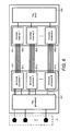
- FIG. 6 shows schematically a first configuration of the example spatial audio signal processing apparatus according to some embodiments
- FIG. 7 shows schematically a second configuration of the example spatial audio signal processing apparatus according to some embodiments.
- FIG. 8 shows schematically a third configuration of the example spatial audio signal processing apparatus according to some embodiments.
- FIG. 9 shows schematically a fourth configuration of the example spatial audio signal processing apparatus according to some embodiments.
- FIG. 10 shows schematically a fifth configuration of the example spatial audio signal processing apparatus according to some embodiments.
- FIG. 11 shows schematically a first user interface display configuration for controlling the example spatial audio signal processing apparatus according to some embodiments
- FIG. 12 shows schematically a second user interface display configuration for controlling the example spatial audio signal processing apparatus according to some embodiments
- FIG. 13 shows schematically a third user interface display configuration for controlling the example spatial audio signal processing apparatus according to some embodiments
- FIG. 14 shows schematically a fourth user interface display configuration for controlling the example spatial audio signal processing apparatus according to some embodiments
- FIG. 15 shows schematically a fifth user interface display configuration for controlling the example spatial audio signal processing apparatus according to some embodiments
- FIG. 16 shows schematically a first example spatial audio signal processing beamform pattern according to some embodiments
- FIG. 17 shows schematically a second example spatial audio signal processing beamform pattern according to some embodiments.
- FIG. 18 shows schematically a third example spatial audio signal processing beamform pattern according to some embodiments.
- FIG. 19 shows schematically a fourth example spatial audio signal processing beamform pattern according to some embodiments.
- FIG. 20 shows schematically a fifth example spatial audio signal processing beamform pattern according to some embodiments.
- FIG. 21 shows schematically a sixth example spatial audio signal processing beamform pattern according to some embodiments.
- FIG. 22 shows schematically a seventh example spatial audio signal processing beamform pattern according to some embodiments.
- FIG. 23 shows schematically an eighth example spatial audio signal processing beamform pattern according to some embodiments.
- mobile devices or apparatus are more commonly being equipped with multiple microphone configurations or microphone arrays suitable for recording or capturing the audio environment or audio scene surrounding the mobile device or apparatus.
- This microphone configuration thus enables the possible recording of stereo or surround sound signals.
- the known location and orientation of the microphones further enables the apparatus to process the captured or recorded audio signals from the microphones to perform spatial processing to emphasise or focus on the audio signals from a defined direction relative to other directions.
- the audio signal recorded by the apparatus is defined with respect to a fixed forward beam or no beam at all.
- the concept of embodiments is therefore to flexibly capture or record multiple audio tracks with different channel configurations.
- the channel configurations can be mono/stereo/surround sound/object processed audio signals and can have various settings.
- one part of the concept covers forming multiple instances (or elements) of processed audio signals (for example beams) for surround sound in real time recording or embedding these within a video.
- an apparatus or device comprising two or more microphones can generate these processing elements or instances and encode the output of the processing elements or instances separately.
- complex processing instances can in some embodiments be generated by combining the output of the processing elements or instances and encoding the combination output.
- the elements or instances can be multichannel (or surround sound) processed outputs, or can be stereo processed outputs or mono processed outputs or audio object processed outputs.
- FIG. 1 shows a schematic block diagram of an exemplary apparatus or electronic device 10 , which may be used to record (or operate as a capture apparatus).
- the electronic device 10 may for example be a mobile terminal or user equipment of a wireless communication system when functioning as the recording apparatus or listening apparatus.
- the apparatus can be an audio player or audio recorder, such as an MP3 player, a media recorder/player (also known as an MP4 player), or any suitable portable apparatus suitable for recording audio or audio/video camcorder/memory audio or video recorder.
- the apparatus 10 can in some embodiments comprise an audio-video subsystem.
- the audio-video subsystem for example can comprise in some embodiments a microphone or array of microphones 11 for audio signal capture.
- the microphone or array of microphones can be a solid state microphone, in other words capable of capturing audio signals and outputting a suitable digital format signal.
- the microphone or array of microphones 11 can comprise any suitable microphone or audio capture means, for example a condenser microphone, capacitor microphone, electrostatic microphone, Electret condenser microphone, dynamic microphone, ribbon microphone, carbon microphone, piezoelectric microphone, or micro electrical-mechanical system (MEMS) microphone.
- MEMS micro electrical-mechanical system
- the microphone 11 is a digital microphone array, in other words configured to generate a digital signal output (and thus not requiring an analogue-to-digital converter).
- the microphone 11 or array of microphones can in some embodiments output the audio captured signal to an analogue-to-digital converter (ADC) 14 .
- ADC an analogue-to-digital converter
- the apparatus can further comprise an analogue-to-digital converter (ADC) 14 configured to receive the analogue captured audio signal from the microphones and outputting the audio captured signal in a suitable digital form.
- ADC analogue-to-digital converter
- the analogue-to-digital converter 14 can be any suitable analogue-to-digital conversion or processing means.
- the microphones are ‘integrated’ microphones containing both audio signal generating and analogue-to-digital conversion capability.
- the apparatus 10 audio-video subsystem further comprises a digital-to-analogue converter 32 for converting digital audio signals from a processor 21 to a suitable analogue format.
- the digital-to-analogue converter (DAC) or signal processing means 32 can in some embodiments be any suitable DAC technology.
- the audio-video subsystem can comprise in some embodiments a speaker 33 .
- the speaker 33 can in some embodiments receive the output from the digital-to-analogue converter 32 and present the analogue audio signal to the user.
- the speaker 33 can be representative of multi-speaker arrangement, a headset, for example a set of headphones, or cordless headphones.
- the apparatus audio-video subsystem comprises a camera 51 or image capturing means configured to supply to the processor 21 image data.
- the camera can be configured to supply multiple images over time to provide a video stream.
- the apparatus audio-video subsystem comprises a display 52 .
- the display or image display means can be configured to output visual images which can be viewed by the user of the apparatus.
- the display can be a touch screen display suitable for supplying input data to the apparatus.
- the display can be any suitable display technology, for example the display can be implemented by a flat panel comprising cells of LCD, LED, OLED, or ‘plasma’ display implementations.
- the apparatus 10 is shown having both audio/video capture and audio/video presentation components, it would be understood that in some embodiments the apparatus 10 can comprise one or the other of the audio capture and audio presentation parts of the audio subsystem such that in some embodiments of the apparatus the microphone (for audio capture) or the speaker (for audio presentation) are present. Similarly in some embodiments the apparatus 10 can comprise one or the other of the video capture and video presentation parts of the video subsystem such that in some embodiments the camera 51 (for video capture) or the display 52 (for video presentation) is present.
- the apparatus 10 comprises a processor 21 .
- the processor 21 is coupled to the audio-video subsystem and specifically in some examples the analogue-to-digital converter 14 for receiving digital signals representing audio signals from the microphone 11 , the digital-to-analogue converter (DAC) 12 configured to output processed digital audio signals, the camera 51 for receiving digital signals representing video signals, and the display 52 configured to output processed digital video signals from the processor 21 .
- DAC digital-to-analogue converter
- the processor 21 can be configured to execute various program codes.
- the implemented program codes can comprise for example audio-video recording and audio-video presentation routines.
- the program codes can be configured to perform audio signal modelling or spatial audio signal processing.
- the apparatus further comprises a memory 22 .
- the processor is coupled to memory 22 .
- the memory can be any suitable storage means.
- the memory 22 comprises a program code section 23 for storing program codes implementable upon the processor 21 .
- the memory 22 can further comprise a stored data section 24 for storing data, for example data that has been encoded in accordance with the application or data to be encoded via the application embodiments as described later.
- the implemented program code stored within the program code section 23 , and the data stored within the stored data section 24 can be retrieved by the processor 21 whenever needed via the memory-processor coupling.
- the apparatus 10 can comprise a user interface 15 .
- the user interface 15 can be coupled in some embodiments to the processor 21 .
- the processor can control the operation of the user interface and receive inputs from the user interface 15 .
- the user interface 15 can enable a user to input commands to the electronic device or apparatus 10 , for example via a keypad, and/or to obtain information from the apparatus 10 , for example via a display which is part of the user interface 15 .
- the user interface 15 can in some embodiments as described herein comprise a touch screen or touch interface capable of both enabling information to be entered to the apparatus 10 and further displaying information to the user of the apparatus 10 .
- the apparatus further comprises a transceiver 13 , the transceiver in such embodiments can be coupled to the processor and configured to enable a communication with other apparatus or electronic devices, for example via a wireless communications network.
- the transceiver 13 or any suitable transceiver or transmitter and/or receiver means can in some embodiments be configured to communicate with other electronic devices or apparatus via a wire or wired coupling.
- the transceiver 13 can communicate with further apparatus by any suitable known communications protocol, for example in some embodiments the transceiver 13 or transceiver means can use a suitable universal mobile telecommunications system (UMTS) protocol, a wireless local area network (WLAN) protocol such as for example IEEE 802.X, a suitable short-range radio frequency communication protocol such as Bluetooth, or infrared data communication pathway (IRDA).
- UMTS universal mobile telecommunications system
- WLAN wireless local area network
- IRDA infrared data communication pathway
- the apparatus comprises a position sensor 16 configured to estimate the position of the apparatus 10 .
- the position sensor 16 can in some embodiments be a satellite positioning sensor such as a GPS (Global Positioning System), GLONASS or Galileo receiver.
- GPS Global Positioning System
- GLONASS Galileo receiver
- the positioning sensor can be a cellular ID system or an assisted GPS system.
- the apparatus 10 further comprises a direction or orientation sensor.
- the orientation/direction sensor can in some embodiments be an electronic compass, accelerometer, and a gyroscope or be determined by the motion of the apparatus using the positioning estimate.
- FIG. 2 an example spatial audio signal processing apparatus according to some embodiments is shown. Furthermore with respect to FIG. 3 a flow diagram of the operation of the spatial audio signal processing apparatus as shown in FIG. 2 is shown.
- the apparatus comprises the microphone or array of microphones 11 which are configured to capture or record the acoustic waves and generate an audio signal for each microphone which is passed to the spatial audio signal processing apparatus.
- the microphones 11 are configured to output an analogue signal which is converted into a digital format by the analogue to digital converter (ADC) 14 .
- ADC analogue to digital converter
- the microphones are integrated microphones configured to output a digital format signal.
- the microphone array is physically separate from the apparatus, for example the microphone array can be located on a headset (where the headset also has an associated video camera capturing the video images which can also be passed to the apparatus and processed in a manner to generate an encoded video signal which can incorporate the processed audio signals as described herein) which wirelessly or otherwise passes the audio signals to the apparatus for processing.
- a headset where the headset also has an associated video camera capturing the video images which can also be passed to the apparatus and processed in a manner to generate an encoded video signal which can incorporate the processed audio signals as described herein) which wirelessly or otherwise passes the audio signals to the apparatus for processing.
- step 201 The operation of receiving the audio signals from the microphone array is shown in FIG. 3 by step 201 .
- the spatial audio signal processing apparatus comprises a pre-processor 101 .
- the pre-processor is configured to receive the audio signals from the microphones and process these to generate audio signals to be used in the processing instances.
- the pre-processor can be configured to equalise the audio signals.
- any suitable processing of the audio signals to enable them to be compared can be performed such as microphone damage or blockage processing.
- Examples of pre-processing that can in some embodiments be applied are: a wind noise reducer configured to reduce the wind noise of the audio signals from the microphones; a handling noise reducer configured to reduce the handling noise of the audio signals from the microphones; a dynamic range compressor configured to dynamically range compress the audio signals from the microphones; a sample rate converter configured to convert the sampling rate of the audio signals from the microphones; and a word length resolution modifier configured to change the word length resolution of the audio signals from the microphones.
- step 203 The operation of pre-processing the microphone array audio signals (for example equalisation) is shown in FIG. 3 by step 203 .
- the pre-processed audio signals from each of the microphones are then passed to an instance processor 103 .
- the spatial audio signal processing apparatus comprises an instance processor 103 .
- the instance processor 103 comprises at least one processing instance, for example at least one instance of surround sound processing, stereo processing, mono processing or object processing.
- the instance processor 103 is configured to utilise the multiple microphone input and from the audio signals from the multiple microphone input analyse the directions of separate audio or sound sources. Furthermore the instance processor 103 can then be configured to process these audio or sound sources, for example to map or synthesise the sounds according to their direction of arrival information into a target multichannel audio reproduction configuration.
- the target multichannel audio reproduction configuration can be a surround sound 5.1 speaker system.
- the surround sound or multichannel audio reproduction configuration can be any suitable channel number or arrangement configuration.
- the instance processor 103 can be configured to output a mono, stereo, or object-based parameter processed output.
- mapping is performed by applying a suitable head related transfer function (HRTF) to the identified audio or sound source.
- HRTF head related transfer function
- a minimum number of microphones are required to perform proper direction recognition. For example in some embodiments a minimum of three microphones in a triangle configuration towards the recording direction are required to get an accurate estimation of the direction.
- audio sounds or signals which have no clear direction can be mapped to an ambience location, for example mapped to any set or combination of front, subwoofer and surround channels.
- the mapping is to the surround channels but also a mapping to all channels can be implemented in some embodiments.
- the instance processor 103 can be configured to further perform surround processing or general processing with respect to a desired direction or section or range of directions.
- the instance processor 103 can be configured to receive a user input indicating a desired direction or range of directions and then process the audio signals from the microphones to provide a processed audio signal having an audio focus or zoom in the desired direction or range of directions.
- the audio focus or zoom processing in some embodiments can be amplification (for example of signals from the desired direction), attenuation (for example of signals from directions other than the desired direction), audio zooming, deemphasising, audio source moving, or filtering.
- the instance processor is configured to generate a focussed audio signal by amplifying audio signals from within a defined direction or region, and attenuating audio signals from outside the defined direction or region.
- This approach is also known as beamforming.
- the amplification and attenuation of the audio signals in some embodiments can be defined as a directionally defined audio filter (or spatial audio filter) configured to spatially filter within a defined directional range the audio signals.
- the spatial filter can be configured to be frequency as well as spatially specific, in other words be configured to filter in both spatial and frequency domains.
- the instance processor can be configured to generate a direction or region defined audio signal amplification configured to amplify within a defined directional range the audio signals for example from the at least two microphones. In other words to amplify audio signals from a defined direction or region but not affect the other audio sources/signals outside of the defined direction or region.
- the instance processor can be configured to generate a direction or region defined audio signal attenuation configured to attenuate within a defined directional range the audio signals, for example from the at least two microphones. In other words to attenuate or nullify audio signals from a defined direction or region but not affect the other audio sources/signals outside of the defined direction or region.
- the instance processor is configured to generate a focussed audio signal by generating a spatially expanded audio signal from the at least two audio signals from the at least two microphones, in other words audio sources from within a defined region can be artificially separated from each other and audio sources outside of the defined region are artificially moved closer together. This approach can produce the effect of producing noticeable audio separation between close audio sources within the defined region while ‘merging’ the audio sources outside of the defined region.
- the instance processor can be configured to operate as an ‘audio de-emphasiser’ configured to apply a reverberation within a defined directional range to any audio source or signals within the region or direction.
- the reverberation can be experienced by the listener as the sound source or audio signals becoming ‘background’ or muffled.
- the instance processor can be configured to displace or move any determined audio sources.
- the instance processor can be configured to modify a relative orientation of an audio source by a defined displacement angle.
- the instance processor 103 may be configured to generate multiple instances, where each instance is configured to perform different processing.
- each instance is shown with a separate analysis, processing and mapping stage it would be understood that in some embodiments different instances can utilise common elements.
- a common analysis part can be utilised by several parallel synthesis parts that produce the different processing outputs.
- both of the instances could use the initial audio scene analysis which identifies or determines audio or sound sources rather than performing redundant analysis in each instance.
- the actual audio source or sound source analysis can be a sub-bands analysis or determination.
- step 205 The operation of generating instances of surround sound/stereo/mono/object instances is shown in FIG. 3 by step 205 .
- the output of the instance processor 103 is passed to an instance mixer 105 .
- the apparatus comprises an instance mixer 105 configured to receive at least a pair of instance processor 103 instance outputs and mix the instance outputs to generate a complex processed output.
- step 206 The operation of mixing instances to generate complex instances is shown in FIG. 3 by step 206 .
- the instance mixer 105 can output the combined instance output to the encoder 107 . Furthermore in some embodiments the instance processor 103 can be configured to output the processed instances to the encoder directly where no mixing is required.
- the apparatus comprises an encoder 107 .
- the encoder 107 can receive the output processed or mixed audio signals from the mixer 105 , and the instance processor 103 and generate at least a single instance of encoder instance in order to encode the output audio signal.
- the encoder 107 can thus generate at least multiple encoding influences and perform the encoding in real time.
- the encoder 107 can be configured to output the encoding to a file multiplexer 109 .
- step 207 The operation of encoding the instance is shown in FIG. 3 by step 207 .
- the apparatus comprises a file multiplexer 109 .
- the file multiplexer 109 is configured to receive the encoded audio signal from the encoder and multiplex these tracks or instances into a single file.
- the file can be a mp4 file containing video that has been recorded on the apparatus at the same time.
- step 209 The operation of storing the encoded instances is shown in FIG. 3 by step 209 .
- FIG. 4 an example instance on the instance processor 103 1 is described in further detail. Furthermore with respect FIG. 5 the operation of the instance processor 103 1 shown in FIG. 4 is shown.
- the instance processor 103 comprises an instance analyser 301 .
- the instance analyser 301 is configured to receive the pre-processed multiple microphone inputs.
- step 401 The operation of receiving the pre-processed audio signal is shown in FIG. 5 by step 401 .
- the instance processor 103 furthermore can in some embodiments be configured to analyse the direction of the separate sound or audio sources (or objects) within the audio scene being recorded.
- the instance analyser 301 is configured to output the detected sources or objects to an instance source/object processor 303 .
- the instance analyser 301 comprises a framer.
- the framer or suitable framer means can be configured to receive the audio signals from the microphones and divide the digital format signals into frames or groups of audio sample data.
- the framer can furthermore be configured to window the data using any suitable windowing function.
- the framer can be configured to generate frames of audio signal data for each microphone input wherein the length of each frame and a degree of overlap of each frame can be any suitable value. For example in some embodiments each audio frame is 20 milliseconds long and has an overlap of 10 milliseconds between frames.
- the framer can be configured to output the frame audio data to a Time-to-Frequency Domain Transformer.
- the instance analyser 301 comprises a Time-to-Frequency Domain Transformer.
- the Time-to-Frequency Domain Transformer or suitable transformer means can be configured to perform any suitable time-to-frequency domain transformation on the frame audio data.
- the Time-to-Frequency Domain Transformer can be a Discrete Fourier Transformer (DFT).
- DFT Discrete Cosine Transformer
- MDCT Modified Discrete Cosine Transformer
- FFT Fast Fourier Transformer
- QMF quadrature mirror filter
- the Time-to-Frequency Domain Transformer can be configured to output a frequency domain signal for each microphone input to a sub-band filter.
- the instance analyser 301 comprises a sub-band filter.
- the sub-band filter or suitable means can be configured to receive the frequency domain signals from the Time-to-Frequency Domain Transformer for each microphone and divide each microphone audio signal frequency domain signal into a number of sub-bands.
- the sub-band division can be any suitable sub-band division.
- the sub-band filter can be configured to operate using psychoacoustic filtering bands.
- the sub-band filter can then be configured to output each domain range sub-band to a direction analyser.
- the instance analyser 301 can comprise a direction analyser.
- the direction analyser or suitable means can in some embodiments be configured to select a sub-band and the associated frequency domain signals for each microphone of the sub-band.
- the direction analyser can then be configured to perform directional analysis on the signals in the sub-band.
- the directional analyser can be configured in some embodiments to perform a cross correlation between the microphone/decoder sub-band frequency domain signals within a suitable processing means.
- the delay value of the cross correlation is found which maximises the cross correlation of the frequency domain sub-band signals.
- This delay can in some embodiments be used to estimate the angle or represent the angle from the dominant audio signal source for the sub-band.
- This angle can be defined as a. It would be understood that whilst a pair or two microphones can provide a first angle, an improved directional estimate can be produced by using more than two microphones and preferably in some embodiments more than two microphones on two or more axes.
- the directional analyser can then be configured to determine whether or not all of the sub-bands have been selected. Where all of the sub-bands have been selected in some embodiments then the direction analyser can be configured to output the directional analysis results. Where not all of the sub-bands have been selected then the operation can be passed back to selecting a further sub-band processing step.
- the direction analyser can perform directional analysis using any suitable method.
- the object detector and separator can be configured to output specific azimuth-elevation values rather than maximum correlation delay values.
- the spatial analysis can be performed in the time domain.
- this direction analysis can therefore be defined as receiving the audio sub-band data;
- the directional analysis as described herein as follows. First the direction is estimated with two channels. The direction analyser finds delay ⁇ b that maximizes the correlation between the two channels for subband b. DFT domain representation of e.g. x k b (n) can be shifted ⁇ b time domain samples using
- X 2, ⁇ b b and X 3 b are considered vectors with length of n b+1 ⁇ n b n b+1 ⁇ n b samples.
- the direction analyser can in some embodiments implement a resolution of one time domain sample for the search of the delay.
- the direction analyser can be configured to generate a sum signal.
- the sum signal can be mathematically defined as.
- the direction analyser is configured to generate a sum signal where the content of the channel in which an event occurs first is added with no modification, whereas the channel in which the event occurs later is shifted to obtain best match to the first channel.
- the direction analyser can be configured to determine actual difference in distance as
- ⁇ 23 v ⁇ ⁇ ⁇ b F s
- Fs is the sampling rate of the signal
- v is the speed of the signal in air (or in water if we are making underwater recordings).
- the angle of the arriving sound is determined by the direction analyser as,
- ⁇ . 2 ⁇ ⁇ cos - 1 ⁇ ( ⁇ 23 2 ⁇ + 2 ⁇ b ⁇ ⁇ ⁇ ⁇ - d 2 2 ⁇ d ⁇ ⁇ b ) ⁇
- d is the distance between the pair of microphones/channel separation
- b is the estimated distance between sound sources and nearest microphone.
- the direction analyser can be configured to use audio signals from a third channel or the third microphone to define which of the signs in the determination is correct.
- the distances in the above determination can be considered to be equal to delays (in samples) of;
- the direction analyser in some embodiments is configured to select the one which provides better correlation with the sum signal.
- the correlations can for example be represented as
- the instance analyser 301 comprises a mid/side signal generator.
- the main content in the mid signal is the dominant sound source found from the directional analysis.
- the side signal contains the other parts or ambient audio from the generated audio signals.
- the mid/side signal generator can determine the mid M and side S signals for the sub-band according to the following equations:
- the mid signal M is the same signal that was already determined previously and in some embodiments the mid signal can be obtained as part of the direction analysis.
- the mid and side signals can be constructed in a perceptually safe manner such that the signal in which an event occurs first is not shifted in the delay alignment.
- the mid and side signals can be determined in such a manner in some embodiments is suitable where the microphones are relatively close to each other. Where the distance between the microphones is significant in relation to the distance to the sound source then the mid/side signal generator can be configured to perform a modified mid and side signal determination where the channel is always modified to provide a best match with the main channel.
- the mid (M), side (S) and direction ( ⁇ ) components of the captured audio signals can be output to an instance source/object processor 303 .
- step 403 The analysis of the audio signal to determine audio or sound source or objects is shown in FIG. 5 by step 403 .
- the instance processor 103 in some embodiments comprises an instance source/object processor 303 .
- the instance source/object processor 303 is configured to receive the determined sources or object values and process these according to any desired requirement, the processing operation based on or dependent on the instance.
- the instance can be generated based on a user input.
- the instance source/object processor 303 can thus be configured to emphasise or deemphasise the source or direction.
- the emphasis can be based on a zooming or focusing and in some embodiments be based on an attenuating or removing of unwanted sounds or objects or in some embodiments a focusing/defocusing by applying a reverberation filter.
- the instance source/object processor 303 can be configured to output the processed sources to a channel mapper 305 .
- one instance can be to pass the mid signal associated with a source which is within a defined region and to remove the mid signal (M) associated with a source which is outside of the region.
- step 405 The operation of processing the source/objects is shown in FIG. 5 by step 405 .
- the instance processor 103 can comprise a channel mapper 305 .
- the channel mapper 305 is configured to receive the processed source/object and generate a output multichannel, stereo or mono output.
- the channel mapper 305 can for example be configured to apply a suitable mapping such as a head related transfer function (HRTF) to the identified sound sources locating them within a suitable stereo headset region.
- HRTF head related transfer function
- the channel mapper 305 can output a single output (mono), two outputs (stereo), or any configuration multichannel output (surround sound).
- mapping the processed object/sources for the instance is shown in FIG. 5 by step 407 .
- channel mapper 305 can be configured to output the mapped audio signal to an encoder instance or to an instance mixer.
- the output of the mapped audio signal is shown in FIG. 5 by step 409 .
- the apparatus receives the audio signals from the microphones, which are shown as more than two microphones.
- the apparatus comprises the pre-processor 101 which carries out the pre-processing as described herein. For example providing generic microphone related processing such as microphone equalisation. It would be understood that in some embodiments although only one pre-processing block is shown for each instance or track that in some embodiments the pre-processor 101 is itself divided into instances of pre-processor or pre-processing instances which perform pre-processing for each of the instances or tracks.
- the instance processor 103 comprises N surround sound instances, a first surround sound processor instance surround processor 1 501 1 , a second surround sound processor instance surround processor 2 501 2 and a N'th surround sound processor instance surround processor N 501 N .
- Each surround sound processing block performs surround sound processing so that it can up mix or down mix if needed. For example from a three microphone input to a 5.1 or 7.1 or stereo output. Furthermore each of the surround sound processor instances can perform a defined instance processing simulating a possible beamforming pattern or other processing as described herein.
- Each of the surround sound processor instances 501 1 to 501 N outputs the multichannel output to the encoder and in particular an encoder instance matching the surround sound processor instance.
- the first surround sound processor instance 501 1 outputs to a first encoder instance 503 1
- the N'th surround sound processor instance outputs to the N'th encoder instance 503 N .
- each surround sound processor there is a separate multichannel encoder.
- the encoder instances 503 1 to 503 N then output the encoded signal to the file multiplexer 109 to be multiplexed together.
- the file multiplexer 109 can be configured to further output the different tracks to separate files which are logically linked together, for example by means of file naming.
- FIG. 7 a second configuration of the example spatial audio signal processing apparatus according to some embodiments is shown.
- the apparatus receives the audio signals from the microphones, which, similar to the configuration shown in FIG. 6 , comprises more than two microphones.
- the apparatus comprises the pre-processor 101 which carries out the pre-processing as described herein.
- the instance processor 103 comprises X surround sound instances, a first surround sound processor instance surround processor 1 501 1 , a second surround sound processor instance surround processor 2 501 2 and a X'th surround sound processor instance surround processor X 501 X .
- Each surround sound processing block performs surround sound processing so that it can up mix or down mix if needed and can perform a defined instance processing for example simulating a possible beamforming pattern.
- the apparatus comprises a mixer 105 configured to receive the output of the first and second instances or tracks.
- the mixer 105 is configured to mix the outputs of the first and second instances or tracks to produce a combined instance output.
- the first instance or track defines a first beamforming pattern and the second instance or track defines a second beamforming pattern then the combined instance or track defines the combination of the two beamforming patterns.
- the mixer can be configured to generate a combination other than an additive or simple additive combination, such as a difference between the tracks or instances or a weighted additive combination.
- two tracks are shown being mixed or combined it would be understood that the number of tracks or instances being mixed or combined can be more than two.
- the combined or mixed instance or track can as shown in FIG. 7 can then output to the encoder 107 , where the instance or track is encoded by an encoding instance, for example encoder instance 503 1 .
- the encoder 107 comprises a X'th encoder instance 503 X configured to receive the X'th surround sound processor instance 501 X .
- each surround sound processor output or combined output there is a separate multichannel encoder.
- the encoder instances 503 1 and 503 X then output the encoded signals to the file multiplexer 109 to be multiplexed together.
- the file multiplexer 109 can be configured to further multiplex the audio tracks or instances to a video track or instance.
- FIG. 8 a third configuration of the example spatial audio signal processing apparatus according to some embodiments is shown.
- the apparatus receives the audio signals from the microphones, which, similar to the configuration shown in FIG. 6 , comprises more than two microphones.
- the apparatus comprises the pre-processor 101 which carries out the pre-processing as described herein.
- the instance processor 103 comprises N surround sound instances, a first surround sound processor instance surround processor 1 501 1 , a second surround sound processor instance surround processor 2 501 2 and a N'th surround sound processor instance surround processor N 501 N .
- Each surround sound processing block performs surround sound processing so that it can up mix or down mix if needed and can perform a defined instance processing for example simulating a possible beamforming pattern.
- the instance processor 103 comprises N stereo instances, a first stereo processor instance stereo processor 1 701 1 , a second stereo processor instance stereo processor 2 701 2 and a N'th stereo processor instance stereo processor N 701 N .
- the stereo processor instances in some embodiments differ from the surround processor instances in that no spatial processing is performed.
- the processing performed on the audio signals can be processing such as sample rate conversion and range compression.
- Each of the surround sound processor instances 501 1 to 501 N outputs the multichannel output to the encoder and in particular an encoder instance matching the surround sound processor instance.
- the first surround sound processor instance 501 1 outputs to a first multichannel encoder instance 503 1 and the N'th surround sound processor instance outputs to the N'th multichannel encoder instance 503 N .
- each of the stereo processor instances 701 1 to 701 N outputs the stereo output to the encoder and in particular an encoder instance matching the stereo processor instance.
- the first stereo processor instance 701 1 outputs to a first stereo encoder instance 703 1 and the N'th stereo processor instance 701 N outputs to the N'th stereo encoder instance 703 N .
- the encoder instances 503 1 to 503 N and 703 1 to 703 N can then be output the encoded signal to the file multiplexer 109 to be multiplexed together.
- the file multiplexer 109 can be configured to further multiplex the audio tracks or instances to a video track or instance.
- FIG. 9 a fourth configuration of the example spatial audio signal processing apparatus according to some embodiments is shown.
- the apparatus receives the audio signals from the microphones, which, similar to the configuration shown in FIG. 6 , comprises more than two microphones.
- the apparatus comprises the pre-processor 101 which carries out the pre-processing as described herein.
- the instance processor 103 comprises a surround sound instance, surround processor 501 .
- the surround sound processing block as described herein is configured to perform surround sound processing so that it can up mix or down mix if needed and can perform a defined instance processing for example simulating a possible beamforming pattern.
- the instance processor 103 comprises a stereo instance, stereo processor 701 .
- the stereo processor instances configured to perform processing such as sample rate conversion and range compression.
- the instance processor 103 furthermore comprises an object instance, object processor 801 .
- the object processor 801 is configured to find or determine the audio objects or sources and output the object or source information.
- the object processor 801 is configured to determine an audio source or object and output this information or a processed version of this information.
- the object processor is configured to output only the audio signal from a single object, in other words the mapper is configured to operate on a single mid signal and angle of arrival in generating the output rather than all of the mid signals and the side signal.
- Each of the outputs from the surround sound instance—surround processor 501 , stereo instance—stereo processor 701 , and object instance—object processor 801 are output to the encoder and in particular an encoder instance matching the instance.
- the surround processor 501 outputs to a multichannel encoder instance 503
- the stereo processor 701 outputs to stereo encoder instance 703
- the object processor 801 outputs to an audio object encoder instance 803 .
- the encoder instances 503 , 703 and 803 then output the encoded signal to the file multiplexer 109 to be multiplexed together.
- the file multiplexer 109 can be configured to further multiplex the audio tracks or instances to a video track or instance.
- the apparatus receives the audio signals from the microphones, which comprises two microphones.
- the apparatus further comprises the pre-processor 101 which carries out the pre-processing as described herein.
- the instance processor 103 comprises N surround sound instances, a first surround sound processor instance surround processor 1 501 1 , a second surround sound processor instance surround processor 2 501 2 and a N'th surround sound processor instance surround processor N 501 N .
- Each surround sound processing block performs surround sound processing so that the processing block can up mix or down mix if needed however the lack of information from the limited number of microphones permits virtual surround processing but does not enable the source location, spatial processing, and beamforming pattern simulation operations as no audio sources or objects can be determined sufficiently accurately. Furthermore similar to the stereo processor instances processing such as sample rate conversion, range compression or other processing, such as stereo widening, can be performed in the surround processors.
- the instance processor 103 comprises N stereo instances, a first stereo processor instance stereo processor 1 701 1 , a second stereo processor instance stereo processor 2 701 2 and a N'th stereo processor instance stereo processor N 701 N .
- the stereo processor instances furthermore do not perform spatial processing.
- the processing performed on the audio signals can be processing such as sample rate conversion and range compression.
- Each of the surround sound processor instances 501 1 to 501 N outputs the multichannel output to the encoder and in particular an encoder instance matching the surround sound processor instance.
- the first surround sound processor instance 501 1 outputs to a first multichannel encoder instance 503 1 and the N'th surround sound processor instance outputs to the N'th multichannel encoder instance 503 N .
- each of the stereo processor instances 701 1 to 701 N outputs the stereo output to the encoder and in particular an encoder instance matching the stereo processor instance.
- the first stereo processor instance 701 1 outputs to a first stereo encoder instance 703 1 and the N'th stereo processor instance 701 N outputs to the N'th stereo encoder instance 703 N .
- the encoder instances 503 1 to 503 N and 703 1 to 703 N can then be output the encoded signal to the file multiplexer 109 to be multiplexed together.
- the file multiplexer 109 can be configured to further multiplex the audio tracks or instances to a video track or instance.
- FIGS. 16 to 23 a series of example beamform patterns which can be generated by surround sound processor instances are shown. It would be understood that the Figures shown herein are examples of possible beamform patterns only and the width of the teardrop patterns (in other words the directionality of the beams) implemented in embodiments can differ from those shown.
- the apparatus 1501 is shown with a front direction 1500 and is configured to record or capture audio signals with a directional gain defined by the beamform pattern distance at an angle of arrival relative to the apparatus.
- the recording is performed without any specific directional gain or directional focus. This is shown in FIG. 16 by the circular beam pattern 1821 surrounding the apparatus 1501 .
- the ‘front zoom’ beamform pattern can be one where the apparatus 1501 (with front direction arrow 1500 ) is shown with a first beamform pattern 2211 (a teardrop shape) directed centrally and to the front and thus indicating a gain or focus directly forward of the apparatus and a second beamform pattern 1513 (also a teardrop shape) directed directly behind and centrally.
- the second beamform pattern 1513 is an example of audio signal processing used to generate the first beamform pattern 2211 .
- the second beamform pattern 1513 can be considered to be a side-effect of the processing of the audio signal required to generated the first beamform 2211 pattern.
- the second beamform pattern 1513 is configured with a lower maximum gain than the first beamform pattern 2211 . This type of beamform pattern configuration can for example be used to follow a video zoom and attempt to record or capture audio signals in front of the apparatus distant from the apparatus.
- the ‘narrator recording’ beamform pattern can be one where the apparatus 1501 (with front direction arrow 1500 ) is shown with a first beamform pattern 2001 (a teardrop shape) directed centrally and to the front and thus indicating a gain or focus directly forward of the apparatus and a second beamform pattern 2003 (also a teardrop shape) directed directly behind and centrally.
- the second beamform pattern 2003 is configured with a larger maximum gain than the first beamform pattern 2001 .
- the first beamform pattern 2001 is an example of audio signal processing used to generate the second beamform pattern 2003 .
- the second beamform pattern 2001 is the desired beamform which also results in the side-effect of generating the first beamform pattern 2001 .
- This type of beamform pattern configuration can for example be used to record audio sources directly in front of the apparatus but focuses on the user of the apparatus.
- the ‘dominant audio source recording’ beamform pattern can be one where the apparatus 1501 (with front direction arrow 1500 ) is shown with a first beamform pattern 2111 (a teardrop shape) directed towards the audio source 1505 and to the front and thus indicating a maximum gain or focus directly towards the audio source and a second beamform pattern 1513 (a side effect teardrop shape similar to that shown in FIG. 17 ) directed directly behind and centrally (similar to the rear beamform pattern shown in FIG. 17 ).
- the second beamform pattern 1513 is configured with a lower maximum gain than the first beamform pattern 2111 .
- This type of beamform pattern configuration can for example be used to record an audio source, for example the loudest audio source, which is off centre from the centre forward direction of the apparatus, in other words in some embodiments away from the centre of the image being recorded by the camera.
- the ‘secondary audio source recording’ beamform pattern can for example be produced by an processing instance determining a dominant or primary audio source, a secondary or minor audio source and the directions of the audio sources and then generating a first beamform pattern 1511 (a teardrop shape) directed towards a minor or secondary audio source 1503 , away from the dominant audio source 1505 and to the front and thus indicating a maximum gain or focus directly towards the secondary or minor audio source and a second beamform pattern 1513 (a side effect teardrop shape similar to that shown in FIGS. 17 and 19 ) directed directly behind and centrally.
- the second beamform pattern 1513 is configured with a lower maximum gain than the first beamform pattern 2111 .
- This type of beamform pattern configuration can for example be used to record an audio source which is not the loudest audio source and which can be off centre from the centre-forward direction of the apparatus. This directed beamform pattern thus suppresses the loudest source with respect to the minor source.
- the ‘tracking audio source recording’ can for example be produced by an processing instance determining an audio source and the direction of the audio source and then generating a beamform pattern having a first beamform pattern 1611 (a teardrop shape) directed towards the audio source 1601 and to the front and thus indicating a maximum gain or focus directly towards the audio source, and furthermore following the direction of the audio source.
- the ‘tracking audio source recording’ can in some embodiments comprise a second beamform pattern 1513 (also a teardrop shape) directed directly behind and centrally (a side effect teardrop shape similar to that shown in FIGS. 17, 19 and 20 ).
- the second beamform pattern 1513 is configured with a lower maximum gain than the first beamform pattern 1611 .
- This type of beamform pattern configuration can for example be used to record an audio source which moves in front of the apparatus without the need for the apparatus to move to track the source.
- the ‘avoid dominant audio source recording’ beamform pattern can for example be performed by an processing instance determining an audio source and the direction of the audio source and then generating a beamform pattern with a first beamform pattern 1711 (a teardrop shape) directed away from the audio source 1505 and to the front and thus indicating a maximum gain or focus away from the audio source and a second beamform pattern 1513 (also a teardrop shape) directed directly behind and centrally (a side effect teardrop shape similar to that shown in FIGS. 17, 19 to 21 ).
- the second beamform pattern 1513 is configured with a lower maximum gain than the first beamform pattern 1711 .
- This type of beamform pattern configuration can for example be used to record an audio environment but attempt to suppress an dominant source, for example the loudest audio source.
- the beamform pattern shown in FIG. 23 is a combination of the beamform pattern shown in FIG. 16 , an ‘unbiased’ beamform and the beamform pattern shown in FIG. 19 , a ‘dominant audio source recording’ pattern.
- the combination which can be produced by a first processing instance generating the ‘unbiased’ beamform pattern and a second processing instance generating the ‘dominant audio source recording’ pattern can be passed to the mixer which is configured to subtract the ‘dominant audio source recording’ output from the ‘unbiased’ output to generate the pattern output shown in FIG. 23 , in other words an ambience recording or capture track.
- FIGS. 11 to 15 a series of example user interface displays are shown which can be used to control the processing instances and mixing operations.
- the basic user interface 1001 is configured to enable a single output to be generated by selecting one simple or complex (combined) track or instance.
- a radio button list or selection list is shown from which one of the selections is used to enable a processing instance to be generated.
- the example list as shown in FIG. 11 comprises a first radio button 1011 labelled omnidirectional surround sound and configured if selected to generate an omnidirectional surround sound or unbiased pattern such as shown in FIG. 16 .
- the example list further comprises a second radio button 1013 labelled audio zoom front and configured if selected to generate a beamform pattern similar to that shown in FIG. 17 .
- the example list also comprises a third radio button 1015 labelled narrator speech configured if selected to generate a beamform pattern similar to that shown in FIG. 18 , and a fourth radio button 1017 labelled loud events configured if selected to generate a dominant audio source recording beamform pattern such as shown in FIG. 19 .
- a second or ‘advanced’ user interface 1100 is shown.
- the advanced user interface 1100 is configured to enable multiple tracks or instances to be generated and possibly multiplexed onto an output signal. For example as shown in FIG. 12 a selection list of tick boxes are provided from which none, one or more tracks or instances can be selected.
- the example list as shown in FIG. 12 comprises a first tick box 1101 labelled zoom front and configured if selected to generate a processing and encoding instance which implements a beamform pattern similar to that shown in FIG. 17 .
- the list also comprises a second tick box 1103 labelled narrator speech configured if selected to generate a processing and encoding instance which implements a beamform pattern similar to that shown in FIG. 18 , a third tick box 1105 labelled loud events configured if selected to generate a processing and encoding instance which implements a dominant audio source recording beamform pattern such as shown in FIG. 19 , and a fourth tick box 1107 labelled ambience and configured if selected to generate a processing, mixing and encoding instance which implements a beamform pattern similar to that shown in FIG. 23 .
- a third or ‘professional’ user interface 1200 is shown.
- the professional user interface 1200 is configured to enable multiple tracks or instances to be generated and possibly multiplexed onto an output signal. For example as shown in FIG. 13 a two selection list of radio buttons are provided from which each of the more tracks or instances can be selected.
- the first audio track, audio track 1 , selection list as shown in FIG. 13 comprises a first radio button 1201 labelled zoom front and configured if selected to generate a processing and encoding instance which implements a beamform pattern similar to that shown in FIG. 17 , a second radio button 1203 labelled ambience and configured if selected to generate a processing, mixing and encoding instance which implements a beamform pattern similar to that shown in FIG. 23 , and a third radio button 1205 labelled narrator speech configured if selected to generate a processing and encoding instance which implements a beamform pattern similar to that shown in FIG. 18 .
- the user can thus generate or control the generation of the first audio track or instance by selecting one of the three options.
- the second audio track, audio track 2 , selection list as shown in FIG. 13 comprises a fourth (for the user interface) radio button 1207 labelled zoom front and configured if selected to generate a processing and encoding instance which implements a beamform pattern similar to that shown in FIG. 17 , a fifth radio button 1209 labelled ambience and configured if selected to generate a processing, mixing and encoding instance which implements a beamform pattern similar to that shown in FIG. 23 , and a sixth radio button 1211 labelled narrator speech configured if selected to generate a processing and encoding instance which implements a beamform pattern similar to that shown in FIG. 18 .
- the user can thus generate or control the generation of the second audio track or instance by selecting one of the three options.
- the user interface can be configured for a defined number of tracks to display a selection of possible instances for each track.
- each track is provided with the same list of options, however it would be understood that in some embodiments the options provided for difference tracks may differ.
- a first selection in a first track may prevent the same option to be made for a second or further track. This can for example be shown in the user interface by the greying out of the radio button selection option which has already been selected in another track.
- the super user interface 1300 is configured to enable complex tracks or instances to be generated and possibly multiplexed onto an output signal by selecting both additional (or additive) and subtracted (or difference) instances to be combined. For example as shown in FIG. 14 two selection lists of tick boxes are provided from each none, one or more tracks or instances can be selected.
- the first ‘additive’ list 1351 as shown in FIG. 14 comprises a first tick box 1301 labelled zoom front and configured if selected to generate a processing and encoding instance which implements a beamform pattern similar to that shown in FIG. 17 .
- the ‘additive’ list 1351 also comprises a second tick box 1303 labelled narrator speech configured if selected to generate a processing and encoding instance which implements a beamform pattern similar to that shown in FIG. 18 and a third tick box 1305 labelled ambience and configured if selected to generate a processing, mixing and encoding instance which implements a beamform pattern similar to that shown in FIG. 23 .
- the second ‘difference’ list 1361 as shown in FIG. 14 comprises a fourth (on the user interface) tick box 1307 labelled zoom front and configured if selected to generate a processing and encoding instance which implements a beamform pattern similar to that shown in FIG. 17 .
- the ‘difference’ list 1361 also comprises a fifth tick box 1309 labelled narrator speech configured if selected to generate a processing and encoding instance which implements a beamform pattern similar to that shown in FIG. 18 and a sixth tick box 1311 labelled ambience and configured if selected to generate a processing, mixing and encoding instance which implements a beamform pattern similar to that shown in FIG. 23 .
- the mixer thus comprises a first mixing instance to generate a complex beamform pattern, for example when the ambience option is selected and a further mixing instance configured to combine the output of the first mixing instance with another instance (either another mixing instance or a processing instance) for example where one instance or track is subtracted from a further track.
- the complex beamform pattern instance is generated as part of the general mixing, for example where an ambience option is selected as an additive track or instance option the mixer receives the ‘unbiased’ beamform instance as an additive track or instance and the ‘dominant audio source recording’ beamform pattern as a difference track or instance to be combined with the other selected tracks (in other words only a single mixing stage is required to mix both simple and complex beamform patterns).
- these lists can be copied to enable further tracks to be generated from combined tracks. In other words more there can be embodiments where there is more than one output track from the selected additive and difference track options.
- the selection lists can be any list arrangement and configuration.
- the additive and difference lists can comprise different lists of options.
- the track user interface 1400 is configured to enable multiple types of tracks or instances to be generated and control the type of tracks that can be possibly multiplexed onto an output signal. For example as shown in FIG. 15 a stereo instance and option, a surround sound track and options, and object audio track and options are enables to be selected from.
- the user interface 1400 comprise a first tick box 1401 labelled stereo track which is configured if selected a stereo processing instance to be generated. Furthermore the settings comprise an audio zoom strength slider 1403 which controls the zoom or gain of the beam pattern applied. It would be understood that in some embodiments further sliders can be implemented to control the selectivity of the ‘zoom’ or other beam. In other words controlling the width of the beam. Similarly it would be understood that in some embodiments sliders can be associated with other spatially processed beam or focussing operations controlling the effect of the beam or the focussing.
- the user interface 1400 further comprises a second tick box 1405 labelled surround sound track which is configured if selected to enable a surround sound processing instance to be generated. Furthermore in some embodiments the user interface 1400 comprises a series of radio button selection options associated with the second tick box which select the type or option of surround sound track processing. For example in FIG. 15 there comprises a first radio button 1407 labelled omnidirectional surround sound and configured if selected and the second tick box is also selected to generate an omnidirectional surround sound or unbiased pattern such as shown in FIG. 16 . The list further comprises a second radio button 1409 labelled front zoom and configured if selected and the second tick box is also selected to generate a beamform pattern similar to that shown in FIG. 17 .
- the user interface 1400 further comprises a third tick box 1411 labelled object audio track which is configured if selected to enable an object processing instance to be generated. Furthermore in some embodiments the user interface 1400 comprises a data entry box or value selection 1413 associated with the third tick box which select the number of objects to be determined within the object audio track processing instance.
- user equipment is intended to cover any suitable type of wireless user equipment, such as mobile telephones, portable data processing devices or portable web browsers, as well as wearable devices.
- the various embodiments of the invention may be implemented in hardware or special purpose circuits, software, logic or any combination thereof.
- some aspects may be implemented in hardware, while other aspects may be implemented in firmware or software which may be executed by a controller, microprocessor or other computing device, although the invention is not limited thereto.
- firmware or software which may be executed by a controller, microprocessor or other computing device, although the invention is not limited thereto.
- While various aspects of the invention may be illustrated and described as block diagrams, flow charts, or using some other pictorial representation, it is well understood that these blocks, apparatus, systems, techniques or methods described herein may be implemented in, as non-limiting examples, hardware, software, firmware, special purpose circuits or logic, general purpose hardware or controller or other computing devices, or some combination thereof.
- the embodiments of this invention may be implemented by computer software executable by a data processor of the mobile device, such as in the processor entity, or by hardware, or by a combination of software and hardware.
- any blocks of the logic flow as in the Figures may represent program steps, or interconnected logic circuits, blocks and functions, or a combination of program steps and logic circuits, blocks and functions.
- the software may be stored on such physical media as memory chips, or memory blocks implemented within the processor, magnetic media such as hard disk or floppy disks, and optical media such as for example DVD and the data variants thereof, CD.
- the memory may be of any type suitable to the local technical environment and may be implemented using any suitable data storage technology, such as semiconductor-based memory devices, magnetic memory devices and systems, optical memory devices and systems, fixed memory and removable memory.
- the data processors may be of any type suitable to the local technical environment, and may include one or more of general purpose computers, special purpose computers, microprocessors, digital signal processors (DSPs), application specific integrated circuits (ASIC), gate level circuits and processors based on multi-core processor architecture, as non-limiting examples.
- Embodiments of the inventions may be practiced in various components such as integrated circuit modules.
- the design of integrated circuits is by and large a highly automated process.
- Complex and powerful software tools are available for converting a logic level design into a semiconductor circuit design ready to be etched and formed on a semiconductor substrate.
- Programs such as those provided by Synopsys, Inc. of Mountain View, Calif. and Cadence Design, of San Jose, Calif. automatically route conductors and locate components on a semiconductor chip using well established rules of design as well as libraries of pre-stored design modules.
- the resultant design in a standardized electronic format (e.g., Opus, GDSII, or the like) may be transmitted to a semiconductor fabrication facility or “fab” for fabrication.
Abstract
Description
X k b(n)=x k(n b +n),n=0, . . . ,n b+1 −n b−1,b=0, . . . ,B−1
where nb is the first index of bth subband. In some embodiments for every subband the directional analysis as described herein as follows. First the direction is estimated with two channels. The direction analyser finds delay τb that maximizes the correlation between the two channels for subband b. DFT domain representation of e.g. xk b(n) can be shifted τb time domain samples using
where Re indicates the real part of the result and * denotes complex conjugate. X2,τ
where Fs is the sampling rate of the signal and v is the speed of the signal in air (or in water if we are making underwater recordings).
where d is the distance between the pair of microphones/channel separation and b is the estimated distance between sound sources and nearest microphone. In some embodiments the direction analyser can be configured to set the value of b to a fixed value. For example b=2 meters has been found to provide stable results.
δb +=√{square root over ((h+b sin({dot over (α)}b))2+(d/2+b cos({dot over (α)}b))2)}
δb −=√{square root over ((h−b sin({dot over (α)}b))2+(d/2+b cos({dot over (α)}b))2)}
where h is the height of an equilateral triangle (where the channels or microphones determine a triangle), i.e.
M′=M*g
where g is defined as
g=1 if θ1<α<θ2
and
g=0 otherwise
where θ1<α<θ2 defines the pass band region (the defined region).
Claims (20)
Applications Claiming Priority (1)
| Application Number | Priority Date | Filing Date | Title |
|---|---|---|---|
| PCT/EP2012/074956 WO2014090277A1 (en) | 2012-12-10 | 2012-12-10 | Spatial audio apparatus |
Related Parent Applications (1)
| Application Number | Title | Priority Date | Filing Date |
|---|---|---|---|
| PCT/EP2012/074956 A-371-Of-International WO2014090277A1 (en) | 2012-12-10 | 2012-12-10 | Spatial audio apparatus |
Related Child Applications (1)
| Application Number | Title | Priority Date | Filing Date |
|---|---|---|---|
| US16/169,493 Continuation US10818300B2 (en) | 2012-12-10 | 2018-10-24 | Spatial audio apparatus |
Publications (2)
| Publication Number | Publication Date |
|---|---|
| US20150317981A1 US20150317981A1 (en) | 2015-11-05 |
| US10127912B2 true US10127912B2 (en) | 2018-11-13 |
Family
ID=47522495
Family Applications (2)
| Application Number | Title | Priority Date | Filing Date |
|---|---|---|---|
| US14/649,013 Active US10127912B2 (en) | 2012-12-10 | 2012-12-10 | Orientation based microphone selection apparatus |
| US16/169,493 Active 2032-12-11 US10818300B2 (en) | 2012-12-10 | 2018-10-24 | Spatial audio apparatus |
Family Applications After (1)
| Application Number | Title | Priority Date | Filing Date |
|---|---|---|---|
| US16/169,493 Active 2032-12-11 US10818300B2 (en) | 2012-12-10 | 2018-10-24 | Spatial audio apparatus |
Country Status (2)
| Country | Link |
|---|---|
| US (2) | US10127912B2 (en) |
| WO (1) | WO2014090277A1 (en) |
Families Citing this family (34)
| Publication number | Priority date | Publication date | Assignee | Title |
|---|---|---|---|---|
| WO2016004258A1 (en) * | 2014-07-03 | 2016-01-07 | Gopro, Inc. | Automatic generation of video and directional audio from spherical content |
| CN105451151B (en) * | 2014-08-29 | 2018-09-21 | 华为技术有限公司 | A kind of method and device of processing voice signal |
| US9762847B2 (en) * | 2014-10-15 | 2017-09-12 | Cvisualevidence, Llc | Digital deposition and evidence recording system |
| US10375472B2 (en) | 2015-07-02 | 2019-08-06 | Dolby Laboratories Licensing Corporation | Determining azimuth and elevation angles from stereo recordings |
| HK1255002A1 (en) | 2015-07-02 | 2019-08-02 | 杜比實驗室特許公司 | Determining azimuth and elevation angles from stereo recordings |
| GB2540175A (en) | 2015-07-08 | 2017-01-11 | Nokia Technologies Oy | Spatial audio processing apparatus |
| EP3151534A1 (en) * | 2015-09-29 | 2017-04-05 | Thomson Licensing | Method of refocusing images captured by a plenoptic camera and audio based refocusing image system |
| US10033928B1 (en) | 2015-10-29 | 2018-07-24 | Gopro, Inc. | Apparatus and methods for rolling shutter compensation for multi-camera systems |
| US9792709B1 (en) | 2015-11-23 | 2017-10-17 | Gopro, Inc. | Apparatus and methods for image alignment |
| US9973696B1 (en) | 2015-11-23 | 2018-05-15 | Gopro, Inc. | Apparatus and methods for image alignment |
| US9848132B2 (en) | 2015-11-24 | 2017-12-19 | Gopro, Inc. | Multi-camera time synchronization |
| WO2017139473A1 (en) | 2016-02-09 | 2017-08-17 | Dolby Laboratories Licensing Corporation | System and method for spatial processing of soundfield signals |
| US9743060B1 (en) | 2016-02-22 | 2017-08-22 | Gopro, Inc. | System and method for presenting and viewing a spherical video segment |
| US9602795B1 (en) | 2016-02-22 | 2017-03-21 | Gopro, Inc. | System and method for presenting and viewing a spherical video segment |
| US9973746B2 (en) | 2016-02-17 | 2018-05-15 | Gopro, Inc. | System and method for presenting and viewing a spherical video segment |
| US9922398B1 (en) | 2016-06-30 | 2018-03-20 | Gopro, Inc. | Systems and methods for generating stabilized visual content using spherical visual content |
| US9934758B1 (en) | 2016-09-21 | 2018-04-03 | Gopro, Inc. | Systems and methods for simulating adaptation of eyes to changes in lighting conditions |
| US10268896B1 (en) | 2016-10-05 | 2019-04-23 | Gopro, Inc. | Systems and methods for determining video highlight based on conveyance positions of video content capture |
| US10043552B1 (en) | 2016-10-08 | 2018-08-07 | Gopro, Inc. | Systems and methods for providing thumbnails for video content |
| US10684679B1 (en) | 2016-10-21 | 2020-06-16 | Gopro, Inc. | Systems and methods for generating viewpoints for visual content based on gaze |
| US10573291B2 (en) | 2016-12-09 | 2020-02-25 | The Research Foundation For The State University Of New York | Acoustic metamaterial |
| GB2559765A (en) * | 2017-02-17 | 2018-08-22 | Nokia Technologies Oy | Two stage audio focus for spatial audio processing |
| US10194101B1 (en) | 2017-02-22 | 2019-01-29 | Gopro, Inc. | Systems and methods for rolling shutter compensation using iterative process |
| GB2561596A (en) * | 2017-04-20 | 2018-10-24 | Nokia Technologies Oy | Audio signal generation for spatial audio mixing |
| GB2562518A (en) * | 2017-05-18 | 2018-11-21 | Nokia Technologies Oy | Spatial audio processing |
| GB201710093D0 (en) | 2017-06-23 | 2017-08-09 | Nokia Technologies Oy | Audio distance estimation for spatial audio processing |
| GB201710085D0 (en) * | 2017-06-23 | 2017-08-09 | Nokia Technologies Oy | Determination of targeted spatial audio parameters and associated spatial audio playback |
| US10178490B1 (en) * | 2017-06-30 | 2019-01-08 | Apple Inc. | Intelligent audio rendering for video recording |
| US10469818B1 (en) | 2017-07-11 | 2019-11-05 | Gopro, Inc. | Systems and methods for facilitating consumption of video content |
| CN107450883B (en) * | 2017-07-19 | 2019-01-29 | 维沃移动通信有限公司 | A kind of audio data processing method, device and mobile terminal |
| EP3477966A4 (en) * | 2017-08-28 | 2019-07-31 | Panasonic Intellectual Property Management Co., Ltd. | Imaging device |
| US10587807B2 (en) | 2018-05-18 | 2020-03-10 | Gopro, Inc. | Systems and methods for stabilizing videos |
| US10432864B1 (en) | 2018-09-19 | 2019-10-01 | Gopro, Inc. | Systems and methods for stabilizing videos |
| US10863296B1 (en) * | 2019-03-26 | 2020-12-08 | Amazon Technologies, Inc. | Microphone failure detection and re-optimization |
Citations (13)
| Publication number | Priority date | Publication date | Assignee | Title |
|---|---|---|---|---|
| US5477270A (en) | 1993-02-08 | 1995-12-19 | Samsung Electronics Co., Ltd. | Distance-adaptive microphone for video camera |
| US5594800A (en) | 1991-02-15 | 1997-01-14 | Trifield Productions Limited | Sound reproduction system having a matrix converter |
| US6421447B1 (en) | 1999-09-30 | 2002-07-16 | Inno-Tech Co., Ltd. | Method of generating surround sound with channels processing separately |
| EP1592008A2 (en) | 2004-04-30 | 2005-11-02 | Van Den Berghe Engineering Bvba | Multi-channel compatible stereo recording |
| US20080051920A1 (en) | 2006-08-28 | 2008-02-28 | Canon Kabushiki Kaisha | Audio information processing apparatus and audio information processing method |
| EP2059066A1 (en) | 2007-11-09 | 2009-05-13 | Creative Technology, LTD. | A multi-mode sound reproduction system and a corresponding method thereof |
| EP2129015A2 (en) | 2008-03-11 | 2009-12-02 | Yamaha Corporation | Audio signal processing system |
| EP2146522A1 (en) | 2008-07-17 | 2010-01-20 | Fraunhofer-Gesellschaft zur Förderung der angewandten Forschung e.V. | Apparatus and method for generating audio output signals using object based metadata |
| US20110013075A1 (en) | 2009-07-17 | 2011-01-20 | Lg Electronics Inc. | Method for processing sound source in terminal and terminal using the same |
| WO2012031605A1 (en) | 2010-09-06 | 2012-03-15 | Fundacio Barcelona Media Universitat Pompeu Fabra | Upmixing method and system for multichannel audio reproduction |
| US20120195433A1 (en) | 2011-02-01 | 2012-08-02 | Eppolito Aaron M | Detection of audio channel configuration |
| US20130226593A1 (en) * | 2010-11-12 | 2013-08-29 | Nokia Corporation | Audio processing apparatus |
| US20140050454A1 (en) * | 2012-08-17 | 2014-02-20 | Nokia Corporation | Multi Device Audio Capture |
Family Cites Families (3)
| Publication number | Priority date | Publication date | Assignee | Title |
|---|---|---|---|---|
| US9552840B2 (en) * | 2010-10-25 | 2017-01-24 | Qualcomm Incorporated | Three-dimensional sound capturing and reproducing with multi-microphones |
| US9055371B2 (en) * | 2010-11-19 | 2015-06-09 | Nokia Technologies Oy | Controllable playback system offering hierarchical playback options |
| US9313599B2 (en) * | 2010-11-19 | 2016-04-12 | Nokia Technologies Oy | Apparatus and method for multi-channel signal playback |
-
2012
- 2012-12-10 WO PCT/EP2012/074956 patent/WO2014090277A1/en active Application Filing
- 2012-12-10 US US14/649,013 patent/US10127912B2/en active Active
-
2018
- 2018-10-24 US US16/169,493 patent/US10818300B2/en active Active
Patent Citations (13)
| Publication number | Priority date | Publication date | Assignee | Title |
|---|---|---|---|---|
| US5594800A (en) | 1991-02-15 | 1997-01-14 | Trifield Productions Limited | Sound reproduction system having a matrix converter |
| US5477270A (en) | 1993-02-08 | 1995-12-19 | Samsung Electronics Co., Ltd. | Distance-adaptive microphone for video camera |
| US6421447B1 (en) | 1999-09-30 | 2002-07-16 | Inno-Tech Co., Ltd. | Method of generating surround sound with channels processing separately |
| EP1592008A2 (en) | 2004-04-30 | 2005-11-02 | Van Den Berghe Engineering Bvba | Multi-channel compatible stereo recording |
| US20080051920A1 (en) | 2006-08-28 | 2008-02-28 | Canon Kabushiki Kaisha | Audio information processing apparatus and audio information processing method |
| EP2059066A1 (en) | 2007-11-09 | 2009-05-13 | Creative Technology, LTD. | A multi-mode sound reproduction system and a corresponding method thereof |
| EP2129015A2 (en) | 2008-03-11 | 2009-12-02 | Yamaha Corporation | Audio signal processing system |
| EP2146522A1 (en) | 2008-07-17 | 2010-01-20 | Fraunhofer-Gesellschaft zur Förderung der angewandten Forschung e.V. | Apparatus and method for generating audio output signals using object based metadata |
| US20110013075A1 (en) | 2009-07-17 | 2011-01-20 | Lg Electronics Inc. | Method for processing sound source in terminal and terminal using the same |
| WO2012031605A1 (en) | 2010-09-06 | 2012-03-15 | Fundacio Barcelona Media Universitat Pompeu Fabra | Upmixing method and system for multichannel audio reproduction |
| US20130226593A1 (en) * | 2010-11-12 | 2013-08-29 | Nokia Corporation | Audio processing apparatus |
| US20120195433A1 (en) | 2011-02-01 | 2012-08-02 | Eppolito Aaron M | Detection of audio channel configuration |
| US20140050454A1 (en) * | 2012-08-17 | 2014-02-20 | Nokia Corporation | Multi Device Audio Capture |
Non-Patent Citations (5)
| Title |
|---|
| "Capturing Multiple Audio Channels", Final Cut Pro 7, Retrieved on Jun. 8, 2015, Webpage available at : http://documentation.apple.com/en/finalcutpro/usermanual/index.html#chapter=19%26section=3%26tasks=true. |
| "Recording Multiple Tracks", Homerecording.com, Retrieved on Jun. 8, 2015, Webpage available at : http://homerecording.com/bbs/general-discussions/newbies/recording-multiple-tracks-292151/. |
| "Soudtrack Pro 3", Apple Inc, User Manual, 2009, 542 pages. |
| "Tuaw Review: Wiretap Studio Shows Polish & Promise", Engadget, Retrieved on Jun. 8, 2015, Webpage available at : http://www.engadget.com/2007/12/20/tuaw-review-wiretap-studio-shows-polish-and-promise/. |
| International Search Report and Written Opinion received for corresponding Patent Cooperation Treaty Application No. PCT/EP2012/074956, dated May 26, 2014, 19 pages. |
Also Published As
| Publication number | Publication date |
|---|---|
| US20190066697A1 (en) | 2019-02-28 |
| WO2014090277A1 (en) | 2014-06-19 |
| US20150317981A1 (en) | 2015-11-05 |
| US10818300B2 (en) | 2020-10-27 |
Similar Documents
| Publication | Publication Date | Title |
|---|---|---|
| US10818300B2 (en) | Spatial audio apparatus | |
| US10932075B2 (en) | Spatial audio processing apparatus | |
| US10382849B2 (en) | Spatial audio processing apparatus | |
| US9820037B2 (en) | Audio capture apparatus | |
| US9781507B2 (en) | Audio apparatus | |
| US10785589B2 (en) | Two stage audio focus for spatial audio processing | |
| US10397699B2 (en) | Audio lens | |
| EP3520216B1 (en) | Gain control in spatial audio systems | |
| US10097943B2 (en) | Apparatus and method for reproducing recorded audio with correct spatial directionality | |
| US11223924B2 (en) | Audio distance estimation for spatial audio processing | |
| US20200068309A1 (en) | Analysis of Spatial Metadata From Multi-Microphones Having Asymmetric Geometry in Devices | |
| US11523241B2 (en) | Spatial audio processing | |
| US9706324B2 (en) | Spatial object oriented audio apparatus |
Legal Events
| Date | Code | Title | Description |
|---|---|---|---|
| AS | Assignment |
Owner name: NOKIA TECHNOLOGIES OY, FINLAND Free format text: ASSIGNMENT OF ASSIGNORS INTEREST;ASSIGNOR:NOKIA CORPORATION;REEL/FRAME:035765/0418 Effective date: 20150116 Owner name: NOKIA CORPORATION, FINLAND Free format text: ASSIGNMENT OF ASSIGNORS INTEREST;ASSIGNORS:YLIAHO, MARKO TAPANI;KOSKI, ARI JUHANI;REEL/FRAME:035807/0913 Effective date: 20130129 |
|
| STCF | Information on status: patent grant |
Free format text: PATENTED CASE |
|
| MAFP | Maintenance fee payment |
Free format text: PAYMENT OF MAINTENANCE FEE, 4TH YEAR, LARGE ENTITY (ORIGINAL EVENT CODE: M1551); ENTITY STATUS OF PATENT OWNER: LARGE ENTITY Year of fee payment: 4 |