EP2128221A1 - Phosphor and method for manufacturing the same, and light-emitting device and display device using phosphor - Google Patents
Phosphor and method for manufacturing the same, and light-emitting device and display device using phosphor Download PDFInfo
- Publication number
- EP2128221A1 EP2128221A1 EP09006731A EP09006731A EP2128221A1 EP 2128221 A1 EP2128221 A1 EP 2128221A1 EP 09006731 A EP09006731 A EP 09006731A EP 09006731 A EP09006731 A EP 09006731A EP 2128221 A1 EP2128221 A1 EP 2128221A1
- Authority
- EP
- European Patent Office
- Prior art keywords
- phosphor
- sio
- mol
- light
- fluorescence
- Prior art date
- Legal status (The legal status is an assumption and is not a legal conclusion. Google has not performed a legal analysis and makes no representation as to the accuracy of the status listed.)
- Withdrawn
Links
Images


Classifications
-
- C—CHEMISTRY; METALLURGY
- C09—DYES; PAINTS; POLISHES; NATURAL RESINS; ADHESIVES; COMPOSITIONS NOT OTHERWISE PROVIDED FOR; APPLICATIONS OF MATERIALS NOT OTHERWISE PROVIDED FOR
- C09K—MATERIALS FOR MISCELLANEOUS APPLICATIONS, NOT PROVIDED FOR ELSEWHERE
- C09K11/00—Luminescent, e.g. electroluminescent, chemiluminescent materials
- C09K11/08—Luminescent, e.g. electroluminescent, chemiluminescent materials containing inorganic luminescent materials
- C09K11/77—Luminescent, e.g. electroluminescent, chemiluminescent materials containing inorganic luminescent materials containing rare earth metals
- C09K11/7728—Luminescent, e.g. electroluminescent, chemiluminescent materials containing inorganic luminescent materials containing rare earth metals containing europium
- C09K11/77342—Silicates
-
- C—CHEMISTRY; METALLURGY
- C09—DYES; PAINTS; POLISHES; NATURAL RESINS; ADHESIVES; COMPOSITIONS NOT OTHERWISE PROVIDED FOR; APPLICATIONS OF MATERIALS NOT OTHERWISE PROVIDED FOR
- C09K—MATERIALS FOR MISCELLANEOUS APPLICATIONS, NOT PROVIDED FOR ELSEWHERE
- C09K11/00—Luminescent, e.g. electroluminescent, chemiluminescent materials
- C09K11/08—Luminescent, e.g. electroluminescent, chemiluminescent materials containing inorganic luminescent materials
- C09K11/59—Luminescent, e.g. electroluminescent, chemiluminescent materials containing inorganic luminescent materials containing silicon
-
- C—CHEMISTRY; METALLURGY
- C09—DYES; PAINTS; POLISHES; NATURAL RESINS; ADHESIVES; COMPOSITIONS NOT OTHERWISE PROVIDED FOR; APPLICATIONS OF MATERIALS NOT OTHERWISE PROVIDED FOR
- C09K—MATERIALS FOR MISCELLANEOUS APPLICATIONS, NOT PROVIDED FOR ELSEWHERE
- C09K11/00—Luminescent, e.g. electroluminescent, chemiluminescent materials
- C09K11/08—Luminescent, e.g. electroluminescent, chemiluminescent materials containing inorganic luminescent materials
- C09K11/77—Luminescent, e.g. electroluminescent, chemiluminescent materials containing inorganic luminescent materials containing rare earth metals
-
- H—ELECTRICITY
- H01—ELECTRIC ELEMENTS
- H01L—SEMICONDUCTOR DEVICES NOT COVERED BY CLASS H10
- H01L2224/00—Indexing scheme for arrangements for connecting or disconnecting semiconductor or solid-state bodies and methods related thereto as covered by H01L24/00
- H01L2224/01—Means for bonding being attached to, or being formed on, the surface to be connected, e.g. chip-to-package, die-attach, "first-level" interconnects; Manufacturing methods related thereto
- H01L2224/42—Wire connectors; Manufacturing methods related thereto
- H01L2224/47—Structure, shape, material or disposition of the wire connectors after the connecting process
- H01L2224/48—Structure, shape, material or disposition of the wire connectors after the connecting process of an individual wire connector
- H01L2224/4805—Shape
- H01L2224/4809—Loop shape
- H01L2224/48091—Arched
Definitions
- the present invention relates to a phosphor, and particularly to a phosphor that includes (Sr 1-x , Ba x ) 3 SiO 5 as a base material and europium (Eu) as an activator and emits orange fluorescence, a method for manufacturing the phosphor, and a light-emitting device and a display device using the phosphor.
- blue light-emitting diodes mainly composed of gallium nitride that can efficiently emit light in a blue light wavelength range have been developed and are widely used.
- a white light-emitting device (white LED) has been developed by combining such a blue LED with a yellow phosphor, which emits yellow fluorescence under excitation with light in a blue-light wavelength range radiated from the blue LED. Since the white LED has a spectrum covering a wide wavelength range, its brightness in consideration of a visibility curve is high. Therefore, the white LED is used for an optical device such as a display device attached to a cellular phone or a camcorder. It is also used as a backlight of liquid crystal displays as a substitute for an existing small lamp or fluorescent lamp or the like. For example, (Y, Gd) 3 (Al, Ga) 5 O 12 :Ce is used as a yellow phosphor.
- the white LED achieved by combining a blue LED with a yellow phosphor has a problem in that color rendering in a red-color region is low due to lack of red-light emission. Accordingly, a red phosphor that emits red fluorescence and an orange phosphor that emits orange fluorescence when excited with light in a blue-light wavelength range are actively developed. However, a red phosphor with an emission wavelength of 600 nm or more necessarily has a high proportion of covalent bonds in its crystal structure. Thus, only a few crystals are available, and sulfides and nitrides are the crystals most reported as a red phosphor.
- Patent Document 1 titled "PHOSPHOR AND TEMPERATURE SENSOR USING THE SAME" provides the following descriptions.
- a base material constituting a phosphor according to the invention of Patent Document 1 is a silicate of an alkaline-earth metal and is represented by a general formula M x (SiO n ) y , where n is a whole number of 3 or more, preferably 3 or more and 5 or less.
- silicon trioxide (SiO 3 ), silicon tetroxide (SiO 4 ), and silicon pentoxide (SiO 5 ) are preferred as the silicate. This is presumably because they can form a suitable crystal structure as a base material of a phosphor.
- M represents one or more kinds of alkaline-earth metal elements.
- the alkaline-earth metals include magnesium (Mg), calcium (Ca), strontium (Sr), barium (Ba), and radium (Ra).
- Sr and Ba are preferred because they can form a suitable crystal structure as a base material of a phosphor.
- An alkaline-earth metal M can be particularly represented by (Ba 1-a , Sr a ), where a is a mixed crystal ratio (0 ⁇ a ⁇ 1).
- x and y each represents a whole number of 1 or more and x is determined in accordance with n and y.
- x ⁇ 1 is preferred. This means that, comparing an alkaline-earth metal with a silicate both contained in a base material on a molar basis, the number of moles of the alkaline-earth metal is larger than or equal to that of the silicate. This is presumably because such a composition is necessary to form a suitable crystal structure as a base material of a phosphor.
- Examples of the silicate of the alkaline-earth metal that satisfies the conditions described above include Ba 3 SiO 5 , Sr 3 SiO 5 , (Ba 1-a , Sr a ) 3 SiO 5 , Ba 2 SiO 4 , and ⁇ -BaSiO 3 .
- Ba 3 SiO 5 , Sr 3 SiO 5 , and (Ba 1-a , Sr a ) 3 SiO 5 have a tetragonal Cs 3 CoCl 5 -type crystal structure.
- the phosphor includes a silicate of the alkaline-earth metal as a base material and lanthanoid ions as an activator, and is represented by a general formula, La:M x (SiO n ) y , where La is a lanthanoid.
- the lanthanoid is one of europium (Eu) and cerium (Ce), and is contained in the phosphor by taking form of Eu 2+ if it is Eu and Ce 3+ if it is Ce, for example.
- Eu or Ce is added to a base material as an oxide by taking form of Eu 2 O 3 if it is Eu and CeO 2 if it is Ce.
- 0.001 to 0.2 atomic percent of the lanthanoid (La) relative to 1 atom of the alkaline-earth metal (M) is preferably added.
- concentration quenching quenching of light
- Examples of the phosphor include Eu 2+ :Ba 3 SiO 5 , Ce 3+ :Ba 3 SiO 5 , Eu 2+ :Sr 3 SiO 5 , Ce 3+ :Sr 3 SiO 5 , Eu 2+ : (Ba 1-a , Sr a ) 3 SiO 5 , Ce 3+ : (Ba 1-a , Sr a ) 3 SiO 5 , Eu 2+ :Ba 2 SiO 4 , Ce 3+ :Ba 2 SiO 4 , Eu2 + :BaSiO 3, and Ce 3+ :BaSiO 3 .
- Patent Document 2 In Japanese Unexamined Patent Application Publication No. 2006-36943 (paragraphs 0012 to 0014 and 0019 to 0020) (Patent Document 2) and Japanese Unexamined Patent Application Publication No. 2007-227928 (paragraphs 0017 and 0027 and Figure 4 ) (Patent Document 3), a Sr 3 SiO 5 phosphor is described, and Patent Document 2 titled "ORANGE PHOSPHOR" provides the following descriptions.
- An orange phosphor according to the invention of Patent Document 2 has a single phase crystal structure represented by the general formula (Sr 1-x , Eu x ) 3 SiO 5 (0 ⁇ x ⁇ 0.10) and exhibits a high-intensity orange light emission with a peak at around 580 nm.
- a phosphor having a single phase crystal structure that matches with a powder X-ray diffraction pattern of Sr 3 SiO 5 registered in Joint Committee on Powder Diffraction Standards (JCPDS) Card No. 26-984 is achieved.
- This phosphor exhibits a high-intensity orange light emission with a peak at around 580 nm.
- the orange phosphor has a crystal structure of Sr 3 SiO 5 and a structure in which part of Sr is replaced with Eu as an activator.
- the ratio in which Sr is replaced with Eu is more than 0% but not more than 10% of the atomic weight of Sr. This is because light emission does not occur if Sr is not replaced with Eu. Furthermore, if more than 10% of Sr is replaced with Eu, the phosphor does not exhibit a high-intensity light emission due to photoexcitation in an ultraviolet to visible range caused by concentration quenching, formation of a multiphase crystal structure, or the like.
- the entire spectra shift to longer wavelengths as the Ba 2+ concentration increases, and the peak wavelength shifts from 570 to 585 nm.
- the second phase, BaSi 4 0 9 is formed when the Ba 2+ concentration exceeds 0.5 mol.
- nitride phosphors Firing at high temperature and pressure in an expensive high-temperature-and-pressure firing furnace and complicated synthetic processes are necessary to synthesize nitride phosphors, which increases manufacturing cost. Since nitrides that are vulnerable to water are used as a starting material to synthesize nitride phosphors, such materials are dry-blended in a glove box. Therefore, paying attention to every detail is necessary for the synthesis.
- the peak wavelength shifts from 570 to 585 nm as the Ba 2+ concentration in Sr 3 SiO 5 :Eu increases, and the shift stops at 585 nm.
- BaSi 4 O 9 is formed when the Ba 2+ concentration exceeds 0.5 mol.
- Non-Patent Document 1 describes a (Sr 2.93-x , Ba x ) 3 SiO 5 :Eu 0.07 phosphor including 7 mol% Eu serving as an activator, but not phosphors having Eu concentrations other than 7 mol%.
- Non-Patent Document 1 does not teach phosphors with peak wavelengths (emission center wavelengths) exceeding 585 nm or phosphors including (Sr 1-x , Ba x )3SiO 5 with x ⁇ 0.1 as the base material represented by (Sr 1-x , Ba x ) 3 SiO 5 and Eu as the activator.
- a phosphor including (Sr 1-x , Ba x ) 3 SiO 5 with x ⁇ 0.2 as a base material and Eu as an activator is not described.
- Non-Patent Document 2 discloses PL spectra of Sr 3 SiO 5 :Eu 2+ under 405 nm-excitation when the Eu concentration is changed to 0.5 mol%, 1.0 mol%, 1.5 mol%, 2.0 mol%, and 3.0 mol%, and that the emission wavelength shifts to longer wavelengths as the Eu concentration increases.
- Non-Patent Document 2 also teaches that, in PL spectra of (Sr 1-x , Ba x ) 3 SiO 5 :Eu 2+ having a Ba concentration of 0 mol%, 20 mol%, 40 mol%, 60 mol%, and 80 mol%, the emission band shifts to longer wavelengths when the Ba concentration is 20 mol%, and to shorter wavelengths when the Ba concentration exceeds 20 mol%.
- Non-Patent Document 2 does not teach a phosphor having a peak wavelength (emission center wavelength) exceeding 600 nm and including (Sr 1-x , Ba x ) 3 SiO 5 with x ⁇ 0.1 as a base material represented by (Sr 1-x , Ba x ) 3 SiO 5 and more than 3 mol% of Eu or 6 mol% or more of Eu as an activator.
- a phosphor that includes (Sr 1-x , Ba x ) 3 SiO 5 with 1 > x ⁇ 0.1 as a base material and europium (Eu) as an activator and that emits orange fluorescence, a method for manufacturing the phosphor, and a light-emitting device and a display device using the phosphor.
- An embodiment of the present invention provides a phosphor including (Sr 1-x , Ba x ) 3 SiO 5 with 1 > x ⁇ 0.1 as a base material; and europium (Eu) as an activator.
- the emission center wavelength of the phosphor is controlled to be 600 nm or more on the basis of a composition ratio of Sr, Ba, and Eu.
- an emission center wavelength is controlled to be 600 nm or more on the basis of a composition ratio of Sr, Ba, and Eu.
- An embodiment of the present invention also provides a light-emitting device that uses the phosphor described above.
- An embodiment of the present invention also provides a display device having the light-emitting device that uses the phosphor described above, as a light source used for irradiating a display section.
- the phosphor according to an embodiment of the present invention includes (Sr 1-x , Ba x ) 3 SiO 5 as a base material with 1 > x ⁇ 0.1 and europium (Eu) as an activator and its emission center wavelength is controlled to be 600 nm or more on the basis of the composition ratio of Sr, Ba, and Eu.
- Eu europium
- a method for manufacturing a phosphor that includes (Sr 1-x , Ba x ) 3 SiO 5 as a base material and Eu as an activator, has an emission center wavelength of 600 nm or more controlled on the basis of the composition ratio of Sr, Ba, and Eu, emits orange fluorescence, and can improve color rendering in a red-color region can be provided.
- the emission intensity of the phosphor is about 1.8 to about 2 times higher than that of a phosphor whose ratio is 0.1.
- the light-emitting device uses the phosphor described above, a light-emitting device that can improve color rendering can be provided.
- the display device includes the light-emitting device that uses the phosphor described above, as a light source used for irradiating a display section, a display device whose color rendering is improved can be provided.
- x ⁇ 0.2 In the phosphor according to an embodiment of the present invention, preferably x ⁇ 0.2.
- a phosphor that has an emission center wavelength of 600 nm or more and can improve color rendering in a red-color region can be achieved.
- a phosphor that has a higher fluorescence intensity than a yellow yttrium-aluminum-garnet (YAG) phosphor ((Y 1.5 , Gd 1.5 )(Al 2 , Ga 3 )O 12 :Ce) emitting yellow fluorescence and that has an emission center wavelength of 606 nm or more and can improve color rendering in a red-color region can be achieved.
- YAG yellow yttrium-aluminum-garnet
- the fluorescence intensity of a (Sr 1-x , Ba x ) 3 SiO 5 :Eu phosphor is about 1.07 to about 1.20 times higher than that of the yellow YAG phosphor.
- 0.8 ⁇ x a phosphor that has an emission center wavelength of 600 nm or more and can improve color rendering in a red-color region can be achieved.
- the phosphor has a higher fluorescence intensity than the yellow YAG phosphor.
- the fluorescence intensity of a (Sr 1-x , Ba x ) 3 SiO 5 :Eu phosphor is about 1.07 to about 1.20 times higher than that of the yellow YAG phosphor.
- 0.5 ⁇ x a phosphor that has a higher fluorescence intensity than the yellow YAG phosphor and that has an emission center wavelength of 600 nm or more and can improve color rendering in a red-color region can be achieved.
- the fluorescence intensity of a (Sr 1-x , Ba x ) 3 SiO 5 :Eu phosphor is about 1.07 to about 1.20 times higher than that of the yellow YAG phosphor.
- the concentration of the activator is preferably 2 mol% or more and 8 mol% or less. At such a concentration, the emission intensity of the phosphor is about 1.8 to about 2 times higher than that of a phosphor having an activator concentration of 10 mol%. Thus, a phosphor that has a high fluorescence intensity and can improve color rendering in a red-color region can be achieved.
- the concentration of the activator is preferably 6 mol% or more and 8 mol% or less. At such a concentration, the emission intensity of the phosphor is about 1.9 to about 2 times higher than that of a phosphor having an activator concentration of 10 mol%. Thus, a phosphor that has a higher fluorescence intensity and can improve color rendering in a red-color region can be achieved.
- the phosphor preferably emits fluorescence when excited with blue light.
- a phosphor can be excited by a light-emitting element that emits the blue light.
- a white light-emitting device can be configured by mixing the blue light and orange fluorescence emitted from the phosphor.
- a display element that uses the light-emitting device as a light source used for irradiating a display section can be achieved.
- the blue light mentioned herein means "light in a blue-light wavelength range", which has a wavelength of 400 to 480 nm (the same shall apply hereinafter).
- the emission intensity of the phosphor is about 1.8 to about 2 times higher than that in the case where the ratio is 0.1.
- a phosphor that has a high fluorescence intensity emits orange fluorescence whose emission center wavelength is 600 nm or more, and can improve color rendering in a red-color region can be achieved.
- x ⁇ 0.2 In the method for manufacturing the phosphor according to an embodiment of the present invention, preferably x ⁇ 0.2.
- x ⁇ 0.2 a method for manufacturing a phosphor that has an emission center wavelength of 600 nm or more and can improve color rendering in a red-color region can be provided.
- x ⁇ 0.5 a method for manufacturing a phosphor that has a higher fluorescence intensity than the yellow YAG phosphor and that has an emission center wavelength of 606 nm or more and can improve color rendering in a red-color region can be provided.
- the fluorescence intensity of a (Sr 1-x , Ba x ) 3 SiO 5 :Eu phosphor is about 1.07 to about 1.20 times higher than that of the yellow YAG phosphor.
- 0.8 ⁇ x a method for manufacturing a phosphor that has an emission center wavelength of 600 nm or more and can improve color rendering in a red-color region can be provided.
- x ⁇ 0.5 a method for manufacturing a phosphor having a higher fluorescence intensity than the yellow YAG phosphor can be provided.
- the fluorescence intensity of a (Sr 1-x , Ba x ) 3 SiO 5 :Eu phosphor is about 1.07 to about 1.20 times higher than that of the yellow YAG phosphor.
- 0.5 ⁇ x a method for manufacturing a phosphor that has a higher fluorescence intensity than the yellow YAG phosphor and that has an emission center wavelength of 600 nm or more and can improve color rendering in a red-color region can be provided.
- the fluorescence intensity of a (Sr 1-x , Ba x ) 3 SiO 5 :Eu phosphor is about 1.07 to about 1.20 times higher than that of the yellow YAG phosphor.
- the concentration of the activator is preferably 2 mol% or more and 8 mol% or less. At such a concentration, the emission intensity of the phosphor is about 1.8 to about 2 times higher than that of a phosphor having an activator concentration of 10 mol%.
- a method for manufacturing a phosphor that has a high fluorescence intensity and can improve color rendering in a red-color region can be provided.
- the concentration of the activator is preferably 6 mol% or more and 8 mol% or less. At such a concentration, the emission intensity of the phosphor is about 1.9 to about 2 times higher than that of a phosphor having an activator concentration of 10 mol%.
- a method for manufacturing a phosphor that has a higher fluorescence intensity and can improve color rendering in a red-color region can be provided.
- the phosphor preferably emits fluorescence when excited with blue light.
- a method for manufacturing a phosphor that can be excited by a light-emitting element that emits the blue light can be provided.
- a white light-emitting device can be configured by mixing the blue light and orange fluorescence emitted from the phosphor.
- a display element that uses the light-emitting device as a light source used for irradiating a display section and a phosphor that can improve color rendering in a red-color region can be achieved.
- the phosphor is preferably excited by a light-emitting element that emits blue light.
- the phosphor emits orange fluorescence when excited with blue light emitted from the light-emitting element, and the orange fluorescence is mixed with the blue light to realize a light-emitting device that emits white light with improved color rendering.
- the phosphor is preferably excited by a light-emitting element that emits blue light.
- the phosphor emits orange fluorescence when excited with blue light emitted from the light-emitting element, and the orange fluorescence is mixed with the blue light to realize a light-emitting device that emits white light with improved color rendering. Since the display device includes such a light-emitting device, a display device with intense light in a red-color region can be achieved.
- a silicon pentoxide phosphor including (Sr 1-x , Ba x ) 3 SiO 5 as a base material and Eu as an activator
- its fluorescence spectrum characteristics resulting from excitation with blue light are considered to significantly vary on the basis of the composition ratio of Sr, Ba, and Eu.
- the width of a fluorescence spectrum, an emission center wavelength, and a peak fluorescence intensity are considered to vary on the basis of not only the composition ratio of Sr and Ba but also that of Eu.
- the variation in the fluorescence spectrum characteristics of the silicon pentoxide phosphor based on the composition ratio of Sr, Ba, and Eu was examined. Consequently, a phosphor with a fluorescence spectrum having a high peak fluorescence intensity in an orange-light wavelength range, an emission center wavelength of 600 nm or more, and a broad distribution ranging from a yellow-light wavelength range to a red-light wavelength range was obtained. It was found that the color rendering in a red-color region could be improved by using this phosphor.
- the phosphor according to an embodiment of the present invention includes (Sr 1-x , Ba x ) 3 SiO 5 with 1 > x ⁇ 0.1 as a base material and Eu as an activator.
- the phosphor has an emission center wavelength of 600 nm or more controlled on the basis of the composition ratio of the Sr, Ba, and Eu, is excited by light in a blue-light wavelength range (blue light; 400 to 480 nm), emits high-intensity orange fluorescence having an emission center wavelength of 600 nm or more, and can improve color rendering in a red-color region. More preferably x ⁇ 0.2. Preferably 0.8 ⁇ x, and more preferably 0.5 ⁇ x.
- the concentration of the activator is preferably 2 mol% or more and 8 mol% or less, more preferably 6 mol% or more and 8 mol% or less.
- the fluorescence intensity of the (Sr 1-x , Ba x ) 3 SiO 5 :Eu phosphor is about 1.07 to about 1.20 times higher than that of the yellow YAG phosphor (Y 1.5 , Gd 1.5 )(Al 2 , Ga 3 )O 12 :Ce.
- the emission intensity of the phosphor is about 1.8 to about 2 times higher than that of a phosphor having an activator concentration of 10 mol%. In the case where the activator concentration is 6 mol% or more and 8 mol% or less, the emission intensity of the phosphor is about 1.9 to about 2 times higher than that of a phosphor having an activator concentration of 10 mol%.
- the emission intensity of the phosphor is about 1.8 to about 2 times higher than that of a phosphor whose ratio is 0.1. In the case where the ratio described above is 0.06 or more and 0.08 or less, the emission intensity of the phosphor is about 1.9 to about 2 times higher than that of a phosphor whose ratio is 0.1.
- the resulting phosphor includes (Sr 1-x , Ba x ) 3 SiO 5 with 1 > x ⁇ 0.1 as a base material and Eu as an activator, where the Eu concentration (molar percent or atomic percent) is 2% or more and 8% or less (0.02 ⁇ (N Eu /N T ) ⁇ 0.08), preferably 6% or more and 8% or less (0.06 ⁇ (N Eu /N T ) ⁇ 0.08).
- the powders are mixed and crushed to prepare a mixture.
- the mixture is fired at 1300°C or more and 1700°C or less to synthesize a phosphor.
- the mixture is preferably fired at 1600°C in an inert gas atmosphere containing 4% or less of hydrogen on a volume basis.
- the compounds respectively including Sr, Ba, Si, and Eu are mainly oxides, carbonates, oxalates, etc., but not limited to these.
- the compounds may be other inorganic salts or organic compounds such as organic salts.
- the mixture is prepared such that the emission center wavelength is controlled to be 600 nm or more on the basis of the composition ratio of Sr, Ba, and Eu;
- the mixture is then fired to synthesize the phosphor.
- the method for manufacturing the phosphor includes a raw material preparation step of weighing the compounds respectively including Sr, Ba, Si, and Eu such that the Eu concentration (molar percent or atomic percent) is 2% or more and 8% or less, preferably 6% or more and 8% or less, and then preparing a mixture by mixing and crushing the compounds; and a firing step of firing the mixture at 1300°C or more and 1700°C or less.
- the emission center wavelength is controlled to be 600 nm or more on the basis of the composition ratio of Sr, Ba, and Eu.
- the mixture is preferably fired at 1600°C for four hours in an inert gas atmosphere containing 4% or less of hydrogen on a volume basis.
- the phosphor that includes (Sr 1-x , Ba x ) 3 SiO 5 as a base material and Eu as an activator, emits high-intensity orange fluorescence with an emission center wavelength of 600 nm or more, and can improve color rendering in a red-color region can be manufactured.
- the emission intensity of the phosphor manufactured by the method described above having a Eu concentration of 2% or more and 8% or less is about 1.8 to about 2 times higher than that of a phosphor having a Eu concentration of 10%.
- the emission intensity of the phosphor having a Eu concentration of 6% or more and 8% or less is about 1.9 to about 2 times higher than that of a phosphor having a Eu concentration of 10%.
- a phosphor according to an embodiment of the present invention is excited by light in a blue-light wavelength range from 400 to 480 nm, has an emission center wavelength of 600 nm or more, and includes (Sr 1-x , Ba x ) 3 SiO 5 with 1 > x ⁇ 0.1 as a base material and Eu as an activator.
- the fluorescence intensity of the (Sr 1-x , Ba x ) 3 SiO 5 :Eu phosphor is about 1.07 to about 1.20 times higher than that of the yellow YAG phosphor (Y 1.5 , Gd 1.5 ) (Al 2 , Ga 3 )O 12 :Ce.
- the phosphor according to an embodiment of the present invention can be suitably used for a light-emitting device and a display device.
- the phosphor can be suitably used for a display device such as a liquid crystal device that uses a light-emitting device such as a white LED.
- a phosphor including (Sr 1-x , Ba x ) 3 SiO 5 (1 > x ⁇ 0.1) as a base material and Eu as an activator is represented by (Sr 1-x , Ba x ) 3 SiO 5 :Eu, where x represents the composition of a base material.
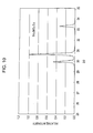
- Fig. 13 is a sectional view of a white light-emitting device (light-emitting device, white LED) that uses the phosphor in an embodiment of the present invention.
- an InGaN blue LED 14 is mounted on the bottom of a reflector cup disposed in a casing 11 and the blue LED 14 is connected to terminal electrodes 13 through bonding wires 15.
- the reflector cup has a depressed portion with a reflecting surface to improve the directivity of light emission by reflection.
- the terminal electrodes 13 are connected to an external power source (not shown).
- the blue LED 14 is sealed, for example, in a molding portion 16 containing a transparent epoxy resin and dispersed orange phosphor according to an embodiment of the present invention.
- a lens for adjusting a divergence angle of emission light may be disposed on the upper surfaces of the molding portion 16 and the casing 11.
- the orange phosphor emits orange fluorescence when excited with light in a blue-light wavelength range emitted from the blue LED 14.
- the orange fluorescence is mixed with the light in a blue-light wavelength range emitted from the blue LED 14, and the white light-emitting device 10 produces white light.
- White light emitted from an existing white light-emitting device achieved by combining a blue LED with a YAG phosphor that emits yellow fluorescence includes less red-light components and exhibits low color rendering in a red-color region.
- white light emitted from the white light-emitting device achieved by combining the blue LED and the orange phosphor according to an embodiment of the present invention is produced by mixing light in a blue-light wavelength range emitted from the blue LED with the orange fluorescence emitted from the orange phosphor, red-light components can be increased and color rendering can be improved.
- a white light-emitting device can be suitably used as a backlight of liquid crystal displays.
- the orange phosphor according to an embodiment of the present invention can be mixed with the YAG phosphor that emits yellow fluorescence.
- the orange phosphor according to an embodiment of the present invention and the YAG phosphor that emits yellow fluorescence can be mixed and dispersed, for example, in a resin constituting the molding portion 16 shown in Fig. 13 such as a transparent epoxy resin.
- This can further increase red-light components and improve color rendering to achieve a white light-emitting device with low color temperature.
- a white light-emitting device as a backlight of a liquid crystal display, a liquid crystal display with brighter light in a red-color region can be achieved.
- the abscissa indicates wavelengths (nm) and the ordinate indicates relative fluorescence intensities.
- (f) is a fluorescence spectrum of a yellow YAG phosphor.
- the Eu concentration of each of the phosphors is 8 mol%, and a method for synthesizing the phosphors (a) to (e) is described below (refer to the descriptions regarding Figs. 3 and 5 ).
- the excitation wavelength is 450 nm.
- the peak wavelengths (emission center wavelengths) of fluorescence spectra of the phosphors (a) to (f) are 595 nm, 602 nm, 610 nm, 608 nm, 588 nm, and 565 nm, respectively.
- the fluorescence spectra were measured with a measurement system Florog 3 available from JOBIN YVON that uses Xe as an excitation light source.
- Each of the emission center wavelengths ⁇ of the fluorescence spectra of (b) (Sr 0.25 , Ba 0.75 ) 3 SiO 5 :Eu, (c) (Sr 0.5 , Ba 0.5 ) 3 SiO 5 :Eu, and (d) (Sr 0.75 , Ba 0.25 ) 3 SiO 5 :Eu is 600 nm or more, which is in an orange-light wavelength range.
- the fluorescence spectra which contain the wavelength components of a yellow-light wavelength range and a red-light wavelength range, are broad.
- Figs. 2A and 2B are graphs showing a relationship between the composition x of a base material and fluorescence properties of (Sr 1-x , Ba x ) 3 SiO 5 :Eu phosphors in Example of the present invention, which are drawn by organizing the results shown in Fig. 1 .
- Fig. 2A shows the peak wavelength (emission center wavelength) of fluorescence spectra as a function of the composition x of a base material.
- Fig. 2B shows the relative fluorescence intensity of fluorescence spectra as a function of the composition x of a base material.
- the relative fluorescence intensity is given as a relative value such that the fluorescence intensities of different phosphors can be compared with each other. Thus, the peak intensity of any phosphor can be used as a reference.
- the amount of the shift reaches its peak and a maximum peak wavelength of about 610 nm is achieved.
- the emission wavelength shifts from the maximum peak wavelength to shorter wavelengths.
- ⁇ is 595 nm.
- each of the emission center wavelengths ⁇ of the fluorescence spectra of (Sr 1-x , Ba x ) 3 SiO 5 :Eu phosphors is longer than the emission center wavelengths ⁇ of the fluorescence spectra of Ba 3 SiO 5 :Eu and Sr 3 SiO 5 :Eu phosphors, and ⁇ is more than 595 nm and the maximum peak wavelength is 610 nm.
- each of the emission center wavelengths ⁇ of fluorescence spectra is 600 nm or more and the maximum peak wavelength is 610 nm.
- each of the emission center wavelengths ⁇ of fluorescence spectra is 606 nm or more and the maximum peak wavelength is 610 nm.
- the fluorescence intensity of a (Sr 1-x , Ba x ) 3 SiO 5 :Eu phosphor is about 1.20 times higher than that of a yellow YAG phosphor (Y 1.5 , Gd 1.5 )(Al 2 , Ga 3 )O 12 :Ce.
- the relative fluorescence intensity of the fluorescence spectra of (Sr 1-x , Ba x ) 3 SiO 5 :Eu phosphors is higher than that of Ba 3 SiO 5 :Eu and Sr 3 SiO 5 :Eu phosphors, and also higher than that of the yellow YAG phosphor (shown with a broken line).
- each of the emission center wavelengths ⁇ of fluorescence spectra is 600 nm or more, and the relative fluorescence intensity of fluorescence spectra is higher than that of any one of the Ba 3 SiO 5 :Eu phosphor, the Sr 3 SiO 5 :Eu phosphor, and the yellow YAG phosphor.
- each of the emission center wavelengths ⁇ of fluorescence spectra is 606 nm or more, and the relative fluorescence intensity of fluorescence spectra is higher than that of the yellow YAG phosphor.
- the fluorescence intensity of the (Sr 1-x , Ba x ) 3 SiO 5 :Eu phosphor is about 1.07 to about 1.20 times higher than that of the yellow YAG phosphor.
- a phosphor having an emission center wavelength of 600 nm or more, which is in an orange-light wavelength range, and a fluorescence spectrum with a broad distribution ranging from a yellow-light wavelength range to a red-light wavelength range was obtained by controlling the composition ratio of Sr and Ba. With this phosphor, color rendering in a red-color region can be improved.
- strontium carbonate, barium carbonate, silicon dioxide, and europium oxide were used as compounds respectively including Sr, Ba, Si, and Eu.
- the powders of these compounds were weighed and blended to prepare a mixture.
- Strontium carbonate, barium carbonate, silicon dioxide, and europium oxide available from Kojundo Chemical Laboratory Co., Ltd. were used.
- the abscissa indicates Eu concentrations (mol%) and the ordinate indicates relative emission intensities (peak fluorescence spectrum intensities) at an excitation wavelength of 450 nm.
- the relative emission intensity of phosphors at the peak wavelengths (emission center wavelengths) of their fluorescence spectra was measured with the excitation light source and the fluorescence spectrometer used for measuring the fluorescence spectra shown in Fig. 1 described above.
- the relative emission intensity slowly increases as the Eu concentration is changed from 2 mol% to 8 mol%. At these Eu concentrations, the emission intensity is about 1.8 to about 2 times higher than that at a Eu concentration of 10 mol%. After the Eu concentration exceeds 8 mol%, the relative emission intensity rapidly decreases.
- the Eu concentration is preferably 2 mol% or more and 8 mol% or less, more preferably 6 mol% or more and 8 mol% or less.
- the emission intensity of the phosphor is about 1.9 to about 2 times higher than that of a phosphor having a Eu concentration of 10 mol%.
- strontium carbonate, barium carbonate, silicon dioxide, and europium oxide were used as compounds respectively including Sr, Ba, Si, and Eu.
- the powders of these compounds were weighed and blended to prepare a mixture.
- Strontium carbonate, barium carbonate, silicon dioxide, and europium oxide available from Kojundo Chemical Laboratory Co., Ltd. were used.
- Phosphors including (Sr 1-x , Ba x ) 3 SiO 5 as a base material and Eu as an activator were synthesized as follows. After 20 g of the mixture prepared by weighing and blending compounds as shown in Figs. 3 and 5 was placed into a 500 mL plastic bottle, 200 ml of ethanol and 200 g of 5 ⁇ zirconia balls were added to the mixture. Ball mill mixing was then conducted at 50 rpm for 30 minutes. The ball-milled mixture was subjected to suction filtration and dried at 80°C for three hours.
- the atmosphere surrounding the dried mixture was created by supplying a homing gas (an inert gas (argon, nitrogen, etc.) containing 4% by volume or less of hydrogen) at 1 L/min and by raising the temperature at 300°C/min.
- a homing gas an inert gas (argon, nitrogen, etc.) containing 4% by volume or less of hydrogen
- the mixture was fired at 1600°C for four hours in the homing gas atmosphere.
- the resultant fired product was crushed and powder X-ray diffraction patterns shown in Figs. 6 to 10 were measured using an X-ray diffractometer (RADIII) available from Rigaku Co., Ltd. with a Ni filter and CuK ⁇ rays (wavelength 0.1541 nm).
- the abscissa indicates diffraction angles 2 ⁇ (degree) and the ordinate indicates relative diffraction intensities.
- Lattice constants a and c were determined as follows using the X-ray diffraction patterns shown in Figs. 6 to 10 , assuming that the (Sr 1-x , Ba x ) 3 SiO 5 :Eu phosphors are tetragonal. The unit of diffraction angle 2 ⁇ is degree.
- Fig. 11 measured X-ray diffraction patterns at a diffraction angle 2 ⁇ of 27° to 34° shown in Fig. 6 (Ba 3 SiO 5 :Eu phosphor), Fig. 8 ((Sr 0.5 , Ba 0.5 ) 3 SiO 5 :Eu phosphor), and Fig. 10 (Sr 3 SiO 5 :Eu phosphor) are superimposed on each other.
- Fig. 6 Ba 3 SiO 5 :Eu phosphor
- Fig. 8 ((Sr 0.5 , Ba 0.5 ) 3 SiO 5 :Eu phosphor) 3 SiO 5 :Eu phosphor)
- Fig. 10 Sr 3 SiO 5 :Eu phosphor
- the diffraction peak of the (Sr 0.5 , Ba 0.5 ) 3 SiO 5 :Eu phosphor is present between the diffraction peaks of the Sr 3 SiO 5 :Eu phosphor and the Ba 3 SiO 5 :Eu phosphor.
- Fig. 12 shows the derived lattice constants a and c (nm) as a function of the composition x of (Sr 1-x , Ba x ) 3 SiO 5 :Eu phosphors.
- the lattice constants a and c are plotted near dashed lines in the drawing and vary linearly with the composition x.
- Vegard's Law holds in this case, and a (Sr 1-x , Ba x ) 3 SiO 5 :Eu phosphor having a desired composition x is considered to have been synthesized.
Applications Claiming Priority (1)
| Application Number | Priority Date | Filing Date | Title |
|---|---|---|---|
| JP2008132705A JP4618330B2 (ja) | 2008-05-21 | 2008-05-21 | 蛍光体とその製造方法、及び、蛍光体を用いた発光デバイス並びに表示デバイス |
Publications (1)
| Publication Number | Publication Date |
|---|---|
| EP2128221A1 true EP2128221A1 (en) | 2009-12-02 |
Family
ID=40848801
Family Applications (1)
| Application Number | Title | Priority Date | Filing Date |
|---|---|---|---|
| EP09006731A Withdrawn EP2128221A1 (en) | 2008-05-21 | 2009-05-19 | Phosphor and method for manufacturing the same, and light-emitting device and display device using phosphor |
Country Status (6)
| Country | Link |
|---|---|
| US (1) | US9663714B2 (zh) |
| EP (1) | EP2128221A1 (zh) |
| JP (1) | JP4618330B2 (zh) |
| KR (1) | KR101612547B1 (zh) |
| CN (1) | CN101586025B (zh) |
| TW (1) | TW201000598A (zh) |
Cited By (1)
| Publication number | Priority date | Publication date | Assignee | Title |
|---|---|---|---|---|
| EP2516586A1 (en) * | 2009-12-21 | 2012-10-31 | Seoul Semiconductor Co., Ltd. | Strontium oxyorthosilicate phosphors having improved stability under a radiation load and resistance to atmospheric humidity |
Families Citing this family (16)
| Publication number | Priority date | Publication date | Assignee | Title |
|---|---|---|---|---|
| JP5748769B2 (ja) | 2009-12-21 | 2015-07-15 | ソウル セミコンダクター カンパニー リミテッド | ストロンチウムオキシオルトシリケート型の蛍光体を有する発光装置 |
| CN101838535B (zh) * | 2010-04-07 | 2013-01-16 | 江苏博睿光电有限公司 | 一种稀土荧光粉及其制造方法 |
| JP5409906B2 (ja) * | 2010-05-25 | 2014-02-05 | 住友金属鉱山株式会社 | Eu賦活アルカリ土類金属シリケート蛍光体の製造方法 |
| EP2591067A1 (de) * | 2010-07-09 | 2013-05-15 | Giesecke & Devrient GmbH | Sicherheitsmerkmal |
| US9614129B2 (en) | 2010-08-14 | 2017-04-04 | Seoul Semiconductor Co., Ltd. | Light emitting device having surface-modified luminophores |
| US9196785B2 (en) | 2010-08-14 | 2015-11-24 | Seoul Semiconductor Co., Ltd. | Light emitting device having surface-modified quantum dot luminophores |
| DE102010034322A1 (de) | 2010-08-14 | 2012-02-16 | Litec-Lp Gmbh | Oberflächenmodifizierter Silikatleuchtstoffe |
| US9234129B2 (en) | 2010-08-14 | 2016-01-12 | Seoul Semiconductor Co., Ltd. | Surface-modified quantum dot luminophores |
| JP5444271B2 (ja) * | 2011-02-24 | 2014-03-19 | 住友金属鉱山株式会社 | アルカリ土類金属シリケート蛍光体の製造方法 |
| TWI421328B (zh) | 2011-09-06 | 2014-01-01 | Ind Tech Res Inst | 螢光材料與白光發光裝置 |
| JP2013067710A (ja) * | 2011-09-21 | 2013-04-18 | Dexerials Corp | 被覆蛍光体の製造方法、被覆蛍光体及び白色光源 |
| CN102760821B (zh) * | 2012-07-10 | 2015-10-07 | 江苏博睿光电有限公司 | 一种白光led光源 |
| CN103811643A (zh) * | 2012-11-12 | 2014-05-21 | 中国航空工业第六一八研究所 | 一种光位移传感器用led光源的制作方法 |
| CN103923644B (zh) * | 2013-01-15 | 2016-08-03 | 兰州大学 | 天然矿物凹凸棒石制备黄色荧光粉Sr3SiO5∶M1,M2(M1=Ce3+或Eu2+,M2=Li+或Ba2+) |
| JP2016028170A (ja) * | 2015-11-11 | 2016-02-25 | デクセリアルズ株式会社 | 被覆蛍光体の製造方法、被覆蛍光体及び白色光源 |
| CN105586034B (zh) * | 2015-12-23 | 2017-11-10 | 上海大学 | 单一基质近紫外激发光色可调的荧光粉及其制备方法 |
Citations (6)
| Publication number | Priority date | Publication date | Assignee | Title |
|---|---|---|---|---|
| JP2005068269A (ja) | 2003-08-22 | 2005-03-17 | Gifu Univ | 蛍光体及びそれを応用した温度センサ |
| JP2006036943A (ja) | 2004-07-28 | 2006-02-09 | Tokyo Kagaku Kenkyusho:Kk | 橙色蛍光体 |
| US20070029526A1 (en) * | 2005-08-03 | 2007-02-08 | Intematix Corporation | Silicate-based orange phosphors |
| JP2007227928A (ja) | 2006-02-22 | 2007-09-06 | Samsung Electro-Mechanics Co Ltd | 白色発光装置 |
| US20080111472A1 (en) * | 2006-11-10 | 2008-05-15 | Intematix Corporation | Aluminum-silicate based orange-red phosphors with mixed divalent and trivalent cations |
| JP2008132705A (ja) | 2006-11-29 | 2008-06-12 | Toray Ind Inc | 炭素繊維積層体およびそれを用いた炭素繊維強化樹脂 |
Family Cites Families (5)
| Publication number | Priority date | Publication date | Assignee | Title |
|---|---|---|---|---|
| JP4690679B2 (ja) | 2004-09-02 | 2011-06-01 | 株式会社北電子 | スロットマシン |
| EP1935958A4 (en) * | 2005-08-10 | 2010-10-27 | Mitsubishi Chem Corp | PHOSPHOR AND LUMINESCENT DEVICE USING THE SAME |
| JP5245222B2 (ja) * | 2005-08-10 | 2013-07-24 | 三菱化学株式会社 | 蛍光体及びそれを用いた発光装置 |
| JP5118837B2 (ja) * | 2005-10-25 | 2013-01-16 | インテマティックス・コーポレーション | シリケート系オレンジ色蛍光体 |
| JP2008081631A (ja) * | 2006-09-28 | 2008-04-10 | Sharp Corp | 発光装置 |
-
2008
- 2008-05-21 JP JP2008132705A patent/JP4618330B2/ja active Active
-
2009
- 2009-04-22 TW TW098113337A patent/TW201000598A/zh unknown
- 2009-05-07 KR KR1020090039730A patent/KR101612547B1/ko active IP Right Grant
- 2009-05-19 EP EP09006731A patent/EP2128221A1/en not_active Withdrawn
- 2009-05-20 CN CN200910142987XA patent/CN101586025B/zh active Active
- 2009-05-20 US US12/469,315 patent/US9663714B2/en active Active
Patent Citations (6)
| Publication number | Priority date | Publication date | Assignee | Title |
|---|---|---|---|---|
| JP2005068269A (ja) | 2003-08-22 | 2005-03-17 | Gifu Univ | 蛍光体及びそれを応用した温度センサ |
| JP2006036943A (ja) | 2004-07-28 | 2006-02-09 | Tokyo Kagaku Kenkyusho:Kk | 橙色蛍光体 |
| US20070029526A1 (en) * | 2005-08-03 | 2007-02-08 | Intematix Corporation | Silicate-based orange phosphors |
| JP2007227928A (ja) | 2006-02-22 | 2007-09-06 | Samsung Electro-Mechanics Co Ltd | 白色発光装置 |
| US20080111472A1 (en) * | 2006-11-10 | 2008-05-15 | Intematix Corporation | Aluminum-silicate based orange-red phosphors with mixed divalent and trivalent cations |
| JP2008132705A (ja) | 2006-11-29 | 2008-06-12 | Toray Ind Inc | 炭素繊維積層体およびそれを用いた炭素繊維強化樹脂 |
Non-Patent Citations (2)
| Title |
|---|
| J. K. PARK ET AL.: "Embodiment of the warm white-light-emitting diodes by using a Ba2+ codoped Sr3SiO5:Eu phosphor", APPL. PHYS. LETT., vol. 88, 2006, pages 043511 - 1 |
| J.K. PARK ET.AL.: "Embodiment of the warm white-light-emitting diodes by using a Ba2+ codoped Sr3SiO5:Eu phosphor", PPLIED PHYSICS LETTERS, vol. 88, 2006, pages 043511-1 - 043511-3, XP002537705 * |
Cited By (2)
| Publication number | Priority date | Publication date | Assignee | Title |
|---|---|---|---|---|
| EP2516586A1 (en) * | 2009-12-21 | 2012-10-31 | Seoul Semiconductor Co., Ltd. | Strontium oxyorthosilicate phosphors having improved stability under a radiation load and resistance to atmospheric humidity |
| EP2516586A4 (en) * | 2009-12-21 | 2013-08-21 | Seoul Semiconductor Co Ltd | STRONTIUM OXYORTHOSILICATE PHOSPHERE OF INCREASED STABILITY UNDER RADIATION EXPOSURE AND STRENGTH TO ATMOSPHERIC HUMIDITY |
Also Published As
| Publication number | Publication date |
|---|---|
| JP4618330B2 (ja) | 2011-01-26 |
| KR101612547B1 (ko) | 2016-04-14 |
| US20090289546A1 (en) | 2009-11-26 |
| US9663714B2 (en) | 2017-05-30 |
| KR20090121207A (ko) | 2009-11-25 |
| TW201000598A (en) | 2010-01-01 |
| CN101586025A (zh) | 2009-11-25 |
| JP2009280664A (ja) | 2009-12-03 |
| CN101586025B (zh) | 2013-01-02 |
Similar Documents
| Publication | Publication Date | Title |
|---|---|---|
| US9663714B2 (en) | Phosphor and method for manufacturing the same, and light-emitting device and display device using phosphor | |
| JP5847908B2 (ja) | オキシ炭窒化物蛍光体およびこれを使用する発光素子 | |
| JP5643424B2 (ja) | 炭窒化物系蛍光体およびこれを使用する発光素子 | |
| TWI344220B (en) | White emitting led with definite color-temperature | |
| JP5779651B2 (ja) | ケイ素カルビドニトリドベースの蛍光体およびこれを使用する発光素子 | |
| US20110248303A1 (en) | METHOD FOR PREPARING A B-SiAION PHOSPHOR | |
| US8928005B2 (en) | Light-emitting device | |
| JP6528418B2 (ja) | 蛍光体及びこれを用いた発光装置 | |
| JP2008533233A (ja) | 放射線源とルミネッセンス材料を含む照明システム | |
| GB2474413A (en) | Method for producing a ß-SiA1ON phosphor | |
| JP2008095091A (ja) | 蛍光体及びその製造方法、蛍光体含有組成物、発光装置、並びに画像表示装置及び照明装置 | |
| CN107636113A (zh) | 荧光体及其制造方法、以及led灯 | |
| JP6094377B2 (ja) | 蛍光体、その蛍光体を用いた蛍光体含有組成物及び発光装置、並びに、その発光装置を用いた照明装置及び画像表示装置 | |
| JP2008007564A (ja) | 酸窒化物系蛍光体及びこれを用いた発光装置 |
Legal Events
| Date | Code | Title | Description |
|---|---|---|---|
| PUAI | Public reference made under article 153(3) epc to a published international application that has entered the european phase |
Free format text: ORIGINAL CODE: 0009012 |
|
| 17P | Request for examination filed |
Effective date: 20090519 |
|
| AK | Designated contracting states |
Kind code of ref document: A1 Designated state(s): AT BE BG CH CY CZ DE DK EE ES FI FR GB GR HR HU IE IS IT LI LT LU LV MC MK MT NL NO PL PT RO SE SI SK TR |
|
| 17Q | First examination report despatched |
Effective date: 20091204 |
|
| RAP1 | Party data changed (applicant data changed or rights of an application transferred) |
Owner name: DEXERIALS CORPORATION |
|
| STAA | Information on the status of an ep patent application or granted ep patent |
Free format text: STATUS: THE APPLICATION IS DEEMED TO BE WITHDRAWN |
|
| 18D | Application deemed to be withdrawn |
Effective date: 20160209 |