EP2119959A1 - Dispositif d'éclairage de véhicule - Google Patents
Dispositif d'éclairage de véhicule Download PDFInfo
- Publication number
- EP2119959A1 EP2119959A1 EP09002350A EP09002350A EP2119959A1 EP 2119959 A1 EP2119959 A1 EP 2119959A1 EP 09002350 A EP09002350 A EP 09002350A EP 09002350 A EP09002350 A EP 09002350A EP 2119959 A1 EP2119959 A1 EP 2119959A1
- Authority
- EP
- European Patent Office
- Prior art keywords
- reflecting surface
- reflecting
- light
- distribution pattern
- light distribution
- Prior art date
- Legal status (The legal status is an assumption and is not a legal conclusion. Google has not performed a legal analysis and makes no representation as to the accuracy of the status listed.)
- Granted
Links
- 238000009792 diffusion process Methods 0.000 claims description 21
- 230000003287 optical effect Effects 0.000 description 12
- 238000010586 diagram Methods 0.000 description 8
- 230000000694 effects Effects 0.000 description 7
- BQCADISMDOOEFD-UHFFFAOYSA-N Silver Chemical compound [Ag] BQCADISMDOOEFD-UHFFFAOYSA-N 0.000 description 3
- XAGFODPZIPBFFR-UHFFFAOYSA-N aluminium Chemical compound [Al] XAGFODPZIPBFFR-UHFFFAOYSA-N 0.000 description 3
- 229910052782 aluminium Inorganic materials 0.000 description 3
- 230000008020 evaporation Effects 0.000 description 3
- 238000001704 evaporation Methods 0.000 description 3
- 238000010422 painting Methods 0.000 description 3
- 229910052709 silver Inorganic materials 0.000 description 3
- 239000004332 silver Substances 0.000 description 3
- 239000000470 constituent Substances 0.000 description 2
- 238000005401 electroluminescence Methods 0.000 description 2
- 230000005855 radiation Effects 0.000 description 2
- 239000000758 substrate Substances 0.000 description 2
- 230000004907 flux Effects 0.000 description 1
- 238000005286 illumination Methods 0.000 description 1
- 238000004519 manufacturing process Methods 0.000 description 1
- 239000000463 material Substances 0.000 description 1
- 239000011347 resin Substances 0.000 description 1
- 229920005989 resin Polymers 0.000 description 1
- 239000004065 semiconductor Substances 0.000 description 1
Images


Classifications
-
- F—MECHANICAL ENGINEERING; LIGHTING; HEATING; WEAPONS; BLASTING
- F21—LIGHTING
- F21S—NON-PORTABLE LIGHTING DEVICES; SYSTEMS THEREOF; VEHICLE LIGHTING DEVICES SPECIALLY ADAPTED FOR VEHICLE EXTERIORS
- F21S41/00—Illuminating devices specially adapted for vehicle exteriors, e.g. headlamps
- F21S41/40—Illuminating devices specially adapted for vehicle exteriors, e.g. headlamps characterised by screens, non-reflecting members, light-shielding members or fixed shades
- F21S41/43—Illuminating devices specially adapted for vehicle exteriors, e.g. headlamps characterised by screens, non-reflecting members, light-shielding members or fixed shades characterised by the shape thereof
-
- F—MECHANICAL ENGINEERING; LIGHTING; HEATING; WEAPONS; BLASTING
- F21—LIGHTING
- F21S—NON-PORTABLE LIGHTING DEVICES; SYSTEMS THEREOF; VEHICLE LIGHTING DEVICES SPECIALLY ADAPTED FOR VEHICLE EXTERIORS
- F21S41/00—Illuminating devices specially adapted for vehicle exteriors, e.g. headlamps
- F21S41/10—Illuminating devices specially adapted for vehicle exteriors, e.g. headlamps characterised by the light source
- F21S41/14—Illuminating devices specially adapted for vehicle exteriors, e.g. headlamps characterised by the light source characterised by the type of light source
- F21S41/141—Light emitting diodes [LED]
- F21S41/147—Light emitting diodes [LED] the main emission direction of the LED being angled to the optical axis of the illuminating device
-
- F—MECHANICAL ENGINEERING; LIGHTING; HEATING; WEAPONS; BLASTING
- F21—LIGHTING
- F21S—NON-PORTABLE LIGHTING DEVICES; SYSTEMS THEREOF; VEHICLE LIGHTING DEVICES SPECIALLY ADAPTED FOR VEHICLE EXTERIORS
- F21S41/00—Illuminating devices specially adapted for vehicle exteriors, e.g. headlamps
- F21S41/10—Illuminating devices specially adapted for vehicle exteriors, e.g. headlamps characterised by the light source
- F21S41/14—Illuminating devices specially adapted for vehicle exteriors, e.g. headlamps characterised by the light source characterised by the type of light source
- F21S41/141—Light emitting diodes [LED]
- F21S41/155—Surface emitters, e.g. organic light emitting diodes [OLED]
-
- F—MECHANICAL ENGINEERING; LIGHTING; HEATING; WEAPONS; BLASTING
- F21—LIGHTING
- F21S—NON-PORTABLE LIGHTING DEVICES; SYSTEMS THEREOF; VEHICLE LIGHTING DEVICES SPECIALLY ADAPTED FOR VEHICLE EXTERIORS
- F21S41/00—Illuminating devices specially adapted for vehicle exteriors, e.g. headlamps
- F21S41/30—Illuminating devices specially adapted for vehicle exteriors, e.g. headlamps characterised by reflectors
- F21S41/32—Optical layout thereof
- F21S41/321—Optical layout thereof the reflector being a surface of revolution or a planar surface, e.g. truncated
-
- F—MECHANICAL ENGINEERING; LIGHTING; HEATING; WEAPONS; BLASTING
- F21—LIGHTING
- F21S—NON-PORTABLE LIGHTING DEVICES; SYSTEMS THEREOF; VEHICLE LIGHTING DEVICES SPECIALLY ADAPTED FOR VEHICLE EXTERIORS
- F21S41/00—Illuminating devices specially adapted for vehicle exteriors, e.g. headlamps
- F21S41/30—Illuminating devices specially adapted for vehicle exteriors, e.g. headlamps characterised by reflectors
- F21S41/32—Optical layout thereof
- F21S41/33—Multi-surface reflectors, e.g. reflectors with facets or reflectors with portions of different curvature
- F21S41/334—Multi-surface reflectors, e.g. reflectors with facets or reflectors with portions of different curvature the reflector consisting of patch like sectors
- F21S41/336—Multi-surface reflectors, e.g. reflectors with facets or reflectors with portions of different curvature the reflector consisting of patch like sectors with discontinuity at the junction between adjacent areas
-
- F—MECHANICAL ENGINEERING; LIGHTING; HEATING; WEAPONS; BLASTING
- F21—LIGHTING
- F21S—NON-PORTABLE LIGHTING DEVICES; SYSTEMS THEREOF; VEHICLE LIGHTING DEVICES SPECIALLY ADAPTED FOR VEHICLE EXTERIORS
- F21S41/00—Illuminating devices specially adapted for vehicle exteriors, e.g. headlamps
- F21S41/30—Illuminating devices specially adapted for vehicle exteriors, e.g. headlamps characterised by reflectors
- F21S41/32—Optical layout thereof
- F21S41/36—Combinations of two or more separate reflectors
- F21S41/365—Combinations of two or more separate reflectors successively reflecting the light
-
- F—MECHANICAL ENGINEERING; LIGHTING; HEATING; WEAPONS; BLASTING
- F21—LIGHTING
- F21S—NON-PORTABLE LIGHTING DEVICES; SYSTEMS THEREOF; VEHICLE LIGHTING DEVICES SPECIALLY ADAPTED FOR VEHICLE EXTERIORS
- F21S45/00—Arrangements within vehicle lighting devices specially adapted for vehicle exteriors, for purposes other than emission or distribution of light
- F21S45/40—Cooling of lighting devices
- F21S45/47—Passive cooling, e.g. using fins, thermal conductive elements or openings
-
- F—MECHANICAL ENGINEERING; LIGHTING; HEATING; WEAPONS; BLASTING
- F21—LIGHTING
- F21V—FUNCTIONAL FEATURES OR DETAILS OF LIGHTING DEVICES OR SYSTEMS THEREOF; STRUCTURAL COMBINATIONS OF LIGHTING DEVICES WITH OTHER ARTICLES, NOT OTHERWISE PROVIDED FOR
- F21V29/00—Protecting lighting devices from thermal damage; Cooling or heating arrangements specially adapted for lighting devices or systems
- F21V29/50—Cooling arrangements
- F21V29/70—Cooling arrangements characterised by passive heat-dissipating elements, e.g. heat-sinks
-
- F—MECHANICAL ENGINEERING; LIGHTING; HEATING; WEAPONS; BLASTING
- F21—LIGHTING
- F21W—INDEXING SCHEME ASSOCIATED WITH SUBCLASSES F21K, F21L, F21S and F21V, RELATING TO USES OR APPLICATIONS OF LIGHTING DEVICES OR SYSTEMS
- F21W2102/00—Exterior vehicle lighting devices for illuminating purposes
- F21W2102/10—Arrangement or contour of the emitted light
- F21W2102/17—Arrangement or contour of the emitted light for regions other than high beam or low beam
- F21W2102/18—Arrangement or contour of the emitted light for regions other than high beam or low beam for overhead signs
-
- F—MECHANICAL ENGINEERING; LIGHTING; HEATING; WEAPONS; BLASTING
- F21—LIGHTING
- F21W—INDEXING SCHEME ASSOCIATED WITH SUBCLASSES F21K, F21L, F21S and F21V, RELATING TO USES OR APPLICATIONS OF LIGHTING DEVICES OR SYSTEMS
- F21W2107/00—Use or application of lighting devices on or in particular types of vehicles
- F21W2107/10—Use or application of lighting devices on or in particular types of vehicles for land vehicles
-
- F—MECHANICAL ENGINEERING; LIGHTING; HEATING; WEAPONS; BLASTING
- F21—LIGHTING
- F21Y—INDEXING SCHEME ASSOCIATED WITH SUBCLASSES F21K, F21L, F21S and F21V, RELATING TO THE FORM OR THE KIND OF THE LIGHT SOURCES OR OF THE COLOUR OF THE LIGHT EMITTED
- F21Y2115/00—Light-generating elements of semiconductor light sources
- F21Y2115/10—Light-emitting diodes [LED]
Definitions
- the present invention relates to a vehicle lighting device employing a semiconductor-type light source as a light source and having a plurality of reflecting surfaces.
- a vehicle lighting device of this type is conventionally disclosed in Japanese Laid-open Patent Application No. 2008-41557 , for example.
- the conventional vehicle lighting device is provided with a semiconductor-type light source, a first reflecting surface, a second reflecting surface, a third reflecting surface, and a fourth reflecting surface.
- the semiconductor-type light source is intended to illuminate and emit light. Part of light radiated from the semiconductor-type light source is then reflected by the first reflecting surface. Part of the reflected light is reflected by the third reflecting surface, and is radiated on a road surface, as a light distribution pattern having a horizontal cut-line on an upper edge.
- the remainder of the reflected light from the first reflecting surface is mainly reflected by the second reflecting surface, and is radiated on a road surface, as a light distribution pattern having a hot spot portion superimposed in the light distribution pattern and a protrusive portion including an oblique cut-line projecting upwardly of the horizontal cut-line.
- the remainder of the light radiated from the semiconductor-type light source is mainly reflected by the fourth reflecting surface, and is radiated on an overhead sign or the like, as an overhead sign light distribution pattern. Therefore, in the conventional vehicle lighting device, an ideal light distribution pattern can be obtained by one lamp unit.
- a problem to be solved by the invention is to improve the conventional vehicle lighting device described previously.
- the invention according to a first aspect is characterised by a vehicle lighting device employing a semiconductor-type light source as a light source and having a plurality of reflecting surfaces, the device including: a first reflecting surface which is an elliptical reflecting surface; the semiconductor-type light source being disposed at or near a first focal point of the first reflecting surface; and parabolic reflecting surfaces for controlling reflected light from the first reflecting surface and reflecting the controlled reflected light as a predetermined light distribution pattern on a road surface, wherein the parabolic reflecting surface is a plurality of longitudinally divided surfaces.
- longitudinal steps are formed among a plurality of parabolic reflecting surfaces which are longitudinally divided.
- the vehicle lighting device of the invention if the reflected light from the first reflecting surface is incident to the longitudinal steps, the incident light is reflected in the lateral direction, i.e., in the transverse direction at the steps.
- the vehicle lighting device of the invention can prevent vertical stray light in comparison with the device in which the reflected light from the first reflecting surface is incident to horizontal steps among the plurality of parabolic reflecting surfaces which are laterally divided, and is reflected in the longitudinal direction, i.e., in the vertical direction at the steps.
- the vehicle lighting device of the invention an ideal light distribution pattern can be obtained by one lamp unit, making it possible to contribute to traffic safety.
- the vehicle lighting device of the invention is effective in a case where a light distribution pattern is a light distribution pattern for passing because the device can prevent vertical stray light.
- the invention according to a second aspect is characterised in that: among the plurality of parabolic reflecting surfaces, the parabolic reflecting surface of an opposite lane side (a lane side on which the other car runs oppositely) is positioned at a light reflecting direction relative to the parabolic reflecting surface of a driving lane side (a lane side on which one's own car runs oppositely).
- the longitudinal steps among the plurality of parabolic reflecting surfaces which are longitudinally divided are oriented to the driving lane side. Therefore, in the vehicle lighting device of the invention, if the reflected light from the first reflecting surface is incident to the longitudinal steps, the incident light is reflected in the lateral direction at the steps and in the direction of the driving lane side. As a result, the vehicle lighting device of the invention can prevent stray light in the lateral direction and in the direction of the opposite lane side. Therefore, the vehicle lighting device of the invention can further obtain an ideal light distribution pattern by one lamp unit, and can further contribute to traffic safety. In particular, the vehicle lighting device of the invention is effective in a case where a light distribution pattern is a light distribution pattern for passing because the device can prevent stray light in the lateral direction and in the direction of the opposite lane side.
- the invention according to a third aspect is characterised in that: the plurality of parabolic reflecting surfaces are made of a second reflecting surface as a middle reflecting surface and third and fourth reflecting surface as left and right reflecting surfaces, the parabolic reflecting surfaces being three longitudinally divided surfaces; the second reflecting surface is a reflecting surface for controlling reflected light from the first reflecting surface and reflecting the controlled reflected light as a light distribution pattern for concentrating light on a road surface; and the third and fourth reflecting surfaces are reflecting surfaces for controlling reflected light from the first reflecting surface and reflecting the controlled reflected light as a light distribution pattern for diffusion on a road surface.
- the second reflecting surface is positioned in the middle of the parabolic reflecting surfaces divided into three sections.
- this second reflecting surface is suitable for controlling the reflected light from the first reflecting surface as a light distribution pattern for concentrating light.
- the third and fourth reflecting surfaces are positioned at the left and right of the parabolic reflecting surfaces longitudinally divided into three sections.
- the third and fourth reflecting surfaces are suitable for controlling the reflected light from the first reflecting surface as a light distribution pattern for diffusion. Therefore, in the vehicle lighting device of the invention, the light distribution pattern for concentrating light, appropriately controlled on the second reflecting surface, are superimposed on the light distribution pattern for diffusion, appropriately controlled on the third and fourth reflecting surfaces.
- a further ideal light distribution pattern can be obtained by one lamp unit, making it possible to further contribute to traffic safety.
- the invention according to a fourth aspect is characterised in that: a shade for cutting off part of the reflected light from the first reflecting surface is provided at or near a second focal point of the first reflecting surface; a shade reflecting surface for reflecting part of the reflected light from the first reflecting surface on the parabolic reflecting surface, cut off by the shade, is provided at the shade; and the plurality of parabolic reflecting surfaces are reflecting surfaces, focal points of which are positioned at or near the second focal point of the first reflecting surface, and further, the reflected light from the first reflecting surface and the reflected light from the shade reflecting surface are controlled and reflected on a road surface, as a light distribution pattern for passing.
- part of the reflected light from the first reflecting surface is cut off by a shade, so that the light distribution pattern for passing, having a cutoff line, can be easily controlled on the parabolic reflecting surfaces longitudinally divided into a plurality of sections.
- part of the reflected light from the first reflecting surface, which is cut off by the shade is reflected by the parabolic reflecting surfaces longitudinally divided into a plurality of sections on the shade reflecting surface, thus making it possible to efficiently utilize the light radiated from the semiconductor-type light source. Therefore, in the vehicle lighting device of the invention, an ideal light distribution pattern for passing can be obtained by one lamp unit, making it possible to contribute to traffic safety.
- the invention according to a fifth aspect is characterised in that: a parabolic reflecting surface for overhead sign, focal points of which are positioned at or near the semiconductor-type light source and light from the semiconductor-type light source is controlled and reflected as a light distribution pattern for overhead sign, is provided upwardly of the plurality of parabolic reflecting surfaces.
- the parabolic reflecting surface for overhead sign is positioned upwardly of the parabolic reflecting surfaces longitudinally divided into a plurality of sections.
- this parabolic reflecting surface for overhead sign is suitable for controlling the light from the semiconductor-type light source as a light distribution pattern for overhead sign. Therefore, in the vehicle lighting device of the invention, ideal light distribution patterns for passing and overhead sign can be obtained by one lamp unit, making it possible to contribute to traffic safety.
- a symbol “F” denotes a vehicle front direction (vehicle forward-moving direction).
- a symbol “B” denotes a vehicle backward direction.
- a symbol “U” denotes an upward direction in which the front direction is seen from a driver's side.
- a symbol “D” denotes a downward direction in which the front direction is seen from the driver's side.
- a symbol “L” denotes a leftward direction in which the front direction is seen from the driver's side.
- a symbol “R” denotes a rightward direction in which the front direction is seen from the driver's side.
- H-H denotes a horizontal axis (an axis parallel to a vehicle forward-moving axis).
- the forward, backward, upward, downward, leftward, rightward, and horizontal directions are equivalent to those in a case where a vehicle is equipped with the vehicle lighting device according to the present invention.
- VU-VD denotes a vertical line of the top and bottom of a screen.
- a symbol “HL-HR” denotes a horizontal line of the left and right of the screen.
- the vehicle lighting device in the embodiment is a four-light system head lamp for passing (for low beam) of a reflector type (reflection type), for example, which is provided at each of the front left and right of a vehicle (automobile).
- the headlamp is used for left-hand traffic in Japan.
- a headlamp used for left-hand traffic in Europe has an arrangement which is substantially similar to that of the aforementioned headlamp.
- headlamps used for right-hand traffic in Europe and for right-hand traffic in North America have an arrangement which is substantially similar to that of the aforementioned headlamps, and are reversely laid out at the left and right.
- the vehicle lighting device in the embodiment is provided with: one lamp unit 1; a lamp housing (not shown); and a lamp lens which is not shown (such as transparent outer lens, for example).
- the lamp unit 1 is disposed in a light room (not shown) which is partitioned by the lamp housing and the lamp lens. Further, the lamp unit 1 is mounted in the lamp housing via a holder, a bracket (not shown), and an optical axis adjuster (not shown).
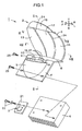
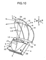
- the lamp unit 1 is made up of a reflector 2, a semiconductor-type light source 3, and a heat sink member 4, as shown in FIG. 1 .
- the reflector 2 is made up of a material such as a light-reflecting resin, for example.
- the reflector 2 is integrally made up of an elliptical portion 5, a parabolic portion 6, an inclined portion 7, and a horizontal portion 8, as shown in FIGS. 1 and 2 .
- the elliptical portion 5 is formed so that the elliptical shape of revolution is divided into four sections in the long-axis and short-axis directions.
- This elliptical portion has a first opening 9 in the long-axis direction and a second opening 10 in the short-axis direction.
- the inclined portion 7 is integrally provided at an edge of the first opening 9 of the elliptical portion 5.
- One edge (front end) of the horizontal portion 8 is integrally provided at one end (upper edge) of the inclined portion 7.
- One edge (lower edge) of the parabolic portion 6 is integrally provided at the other edge (rear edge) of the horizontal portion 8.
- the elliptical portion 5 is positioned at the frontally obliquely lower side relative to the parabolic portion 6.
- the parabolic portion 6 is opposite to the second opening 10 of the elliptical portion 5.
- the inclined portion 7, at one edge (upper edge), is inclined in a direction opposite to a light radiating direction of the lamp unit 1 (to the backside), and, at the other edge (lower edge), is inclined in the light radiating direction of the lamp unit 1 (to the front side), relative to the horizontal portion 8.
- the horizontal portion 8 is (substantially) parallel to the horizontal axis H-H.
- optical parts such as a first reflecting surface 11, a second reflecting surface 12, a third reflecting surface 13, a fourth reflecting surface 14, a fifth reflecting surface 15, a shade 16, and a shade reflecting surface 17, are integrally arranged.
- aluminum evaporation or silver painting is applied to an interior face opposite to the first and second openings 9 and 10 of the elliptical portion 5, and the first reflecting surface 11 is integrally formed.
- Aluminum evaporation or silver painting is applied to an interior face opposite to the second opening 10 and the first reflecting surface 11 of the parabolic portion 6, and the second, third, fourth, and fifth reflecting surfaces 12, 13, 14, and 15 are integrally formed.
- the shade 16 is integrally formed at one edge (upper edge) of the inclined portion 7.
- Aluminum evaporation or silver painting is applied to a face opposite to the second opening 10, the first reflecting surface 11, the second reflecting surface 12, the third reflecting surface 13, and the fourth reflecting surface 14 of the shade 16, and the shade reflecting surface 17 is integrally formed.
- the semiconductor-type light source 3 for example, a self-luminous semiconductor-type light source such as an LED or an electroluminescence (organic electroluminescence) (an LED in the embodiment) is used.
- the semiconductor-type light source 3, as shown in FIG 2 is made of: a substrate 18; a light source chip 19 which is provided on one face of the substrate 18; and a hemispherical (dome-shaped) optically transparent member (lens) 20 covering the light source chip 19.
- the light source chip 19 is formed in a rectangular shape in this example.
- the semiconductor-type light source 3 is fixed to the heat sink member 4 by means of a screw 22 via a holder 21.
- the inclined portion 7 of the reflector 2 is fixed to the heat sink member 4 by means of a screw 23.
- the lamp unit 1 is constituted.
- the first opening 9 of the elliptical portion 5 of the reflector 2 is closed by the heat sink member 4.
- the first reflecting surface 11 of the elliptical portion 5 of the reflector 2 is opposite to the semiconductor-type light source 3.
- the light source chip 19 formed in a rectangular shape, of the semiconductor-type light source 3, is (substantially) orthogonal to the horizontal axis (vehicle forward-moving axis) H-H.
- the semiconductor-type light source 3 has an arrangement which is similar to that of a transverse differential bulb (a bulb of which columnar filament is (substantially) orthogonal to the horizontal axis (vehicle forward-moving axis) H-H).
- a transverse differential bulb a bulb of which columnar filament is (substantially) orthogonal to the horizontal axis (vehicle forward-moving axis) H-H.
- two screws 23 for fixing the reflector 2 to the heat sink member 4 are shown, whereas two screws are not shown.
- the first reflecting surface 11 is an elliptical reflecting surface.
- the elliptical reflecting surface is a reflecting surface which is made up of a free curved surface with an ellipsoid being a key (base, reference) surface or is a reflecting surface which is made up of a surface having an ellipsoid of revolution.
- the reflecting surface made of a free curved surface with an ellipsoid being a key (base, reference) surface is a reflecting surface by which the vertical cross section of FIG. 2 forms an ellipsoid and a horizontal cross section (not shown) is made of a parabola, a deformed parabola or ellipsoid, or a combination thereof.
- the first reflecting surface 11 that is an elliptical reflecting surface has an optical axis Z1-Z1, a first focal point F11, and a second focal point (or second focal radiation) F12.
- the optical axis Z1-Z1 of the first reflecting surface 11 is inclined relative to the horizontal axis H-H when viewed from a side face.
- the first focal point F11 is positioned at the frontally obliquely lower side relative to the second focal point F12.
- the light source chip 19 of the semiconductor-type light source 3 is positioned at or near the first focal point F11 of the first reflecting surface 11.
- a majority L1 of light radiated from the light source chip 19 of the semiconductor-type light source 3 is reflected by the first reflecting surface 11, and converges (gathers) at or near the second focal point F12 of the first reflecting surface 11.
- the second, third, fourth, and fifth reflecting surfaces 12, 13, 14, and 15 are parabolic reflecting surfaces.
- the parabolic reflecting surfaces are reflecting surfaces which are made up of free curved surfaces with a parabola being a key (base, reference) surface or reflecting surfaces which are made of surfaces having a parabola of revolution.
- the reflecting surfaces made of free curved surfaces with a parabola being a key (base, reference) surface are reflecting surface by which the vertical cross section of FIG. 2 forms a parabola and a horizontal cross section (not shown) is made of an ellipsoid, a deformed ellipsoid or parabola, or a combination thereof.
- the second, third, fourth, and fifth reflecting surfaces 12, 13, 14, and 15, all of which are parabolic reflecting surfaces have optical axes Z2-Z2, Z3-Z3, Z4-Z4, Z5-Z5, and focal points (focal radiations) F2, F3, F4, F5.
- the optical axes Z2-Z2, Z3-Z3, Z4-Z4, Z5-Z5 of the second, third, fourth, and fifth reflecting surfaces 12, 13, 14, and 15 are (substantially) parallel to the horizontal axis H-H when viewed from the side face.
- the focal points F2, F3, F4 of the second, third, and fourth reflecting surfaces 12, 13, and 14 are positioned at or near the second focal point F12 of the first reflecting surface 11.
- a focal point F5 of the fifth reflecting surface 15 is positioned at or near the first focal point F11 of the first reflecting surface 11.
- the first reflecting surface 11 is positioned at the frontally obliquely lower side relative to the second, third, fourth, and fifth reflecting surfaces 12, 13, 14, and 15.
- An opening for passing reflected light from the first reflecting surface 11 and direct light from the semiconductor-type light source 3 to the second, third, fourth, and fifth reflecting surfaces 12, 13, 14, and 15, i.e., the second opening 10 is provided between a side on which the first reflecting surface 11 and the semiconductor light source 3 are present and a side on which the second, third, fourth, and fifth reflecting surfaces 12, 13, 14, and 15 are present.
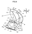
- the shade 16 cuts off part L3 of reflected light L2 from the first reflecting surface 11.
- An edge of the shade 16, i.e., a corner between the inclined portion 7 and the horizontal portion 8 is involved in forming a cutoff line of a light distribution pattern.
- the shade reflecting surface 17 reflects the part L3 of the reflected light L2 from the first reflecting surface 11, the part being cut off by the shade 16, on the second, third, and fourth reflecting surfaces 12, 13, and 14.
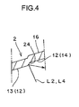
- the second, third, and fourth reflecting surfaces 12, 13, and 14 as parabolic reflecting surfaces are longitudinally divided as shown in FIG 1 .
- the second reflecting surface 12 is positioned between the third and fourth ones.
- the third reflecting surface 13 is positioned at the right side of the second reflecting surface 12.
- the fourth reflecting surface 14 is positioned at the left side of the second reflecting surface 12.
- the third reflecting surface 13 at the opposite lane side (right side) is positioned at the light reflecting direction (front side) relative to the second reflecting surface 12 of the driving lane side (left side).
- the second reflecting surface 12 at the opposite lane side (right side) is positioned at the light reflecting direction (front side) relative to the fourth reflecting surface 14 of the driving lane side (left side).
- longitudinal steps 24 among the longitudinally divided second, third, and fourth reflecting surfaces 12, 13, and 14 are oriented to the driving lane side (left side).
- the second, third, and fourth reflecting surfaces 12, 13, and 14 are reflecting surfaces by which reflected light L2 from the first reflecting surface 11 (reflected light L2 from the first reflecting surface 11 that has not been cut off by the shade 16) and reflected light L4 from the shade reflecting surface 17 (part L3 of reflected light L2 from the first reflecting surface 11 cut off by the shade 16) are controlled and reflected on a road surface, as a light distribution pattern LP for passing shown in FIGS. 5 and 12 .
- a horizontal cutoff line CL1 and an oblique cutoff line CL2 are formed at the upper edge of the light distribution pattern LP for passing.
- the horizontal cutoff line CL1 and the oblique cutoff line CL2, of the light distribution pattern LP for passing are formed by an edge of the shade 16 and the second, third, and fourth reflecting surfaces 12, 13, and 14.
- the horizontal cutoff line CL1 of the light distribution pattern LP for passing is positioned by about 0.57 degree lower than the horizontal left-right line HL-HR of a screen.
- the oblique cutoff line CL2 of the light distribution pattern LP for passing is inclined by about 15 to 45 degrees leftward from the vertical up-down line VU-VD of the screen of the horizontal cutoff line CL1.
- the second reflecting surface 12 is a reflecting surface by which the reflected light L2 from the first reflecting surface 11 and the reflected light L4 from the shade reflecting surface 17 are controlled and reflected on a road surface, as a light distribution pattern SP for concentrating light shown in FIG. 7 .
- the horizontal cutoff line CL1 and the oblique cutoff line CL2 are formed at the upper edge of the light distribution pattern SP for concentrating light.
- the horizontal cutoff line CL1 and the oblique cutoff line CL2, of the light distribution pattern SP for concentrating light are formed by an edge of the shade 16 and the second reflecting surface 12.
- the light distribution pattern SP for concentrating light is a hot spot of the light distribution pattern LP for passing, and satisfies main light distribution standards for the light distribution pattern LP for passing.
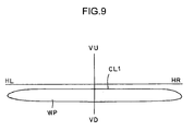
- the third and fourth reflecting surfaces 13 and 14 are reflecting surfaces by which the reflected light L2 from the first reflecting surface 11 and the reflected light L4 from the shade reflecting surface 17 are controlled and reflected on a road surface, as a light distribution pattern WP for diffusion, shown in FIG. 9 .
- the horizontal cutoff line CL1 is formed on the upper edge of the light distribution pattern WP for diffusion.
- the horizontal cutoff line CL1 of the light distribution pattern WP for diffusion is formed by an edge of the shade 16 and the third and fourth reflecting surfaces 13 and 14.
- the light distribution pattern WP for diffusion is horizontal diffusion of the light distribution pattern LP for passing, and forms diffused light distribution which improves marketability of the light distribution pattern LP for passing.
- the horizontal cutoff line CL1 of the light distribution pattern WP for diffusion may be set by about 0.3 to 1 degree lower than the horizontal cutoff line CL1 of the light distribution pattern SP for concentrating light.
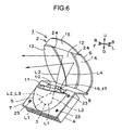
- the fifth reflecting surface 15, as shown in FIG. 1 is positioned upwardly of the second, third, and fourth reflecting surfaces 12, 13, and 14, all of which are those longitudinally divided.
- the fifth reflecting surface 15 is a reflecting surface by which light (direct light) L5 from the semiconductor-type light source 3 is controlled and reflected as a light distribution pattern OP for overhead sign.
- the light distribution pattern OP for overhead sign is positioned upwardly of the horizontal left-right lines HL-HR of a screen, and illuminates an overhead sign, although not shown.
- Parabolic reflecting surfaces are divided into four segments, the second, third, fourth, and fifth reflecting surfaces 12, 13, 14, and 15. Further, the second, third, fourth, and fifth reflecting surfaces 12, 13, 14, and 15 are made of single or multiple segments, in accordance with light distribution characteristics, respectively.
- a vehicle lighting device in the embodiment is made of constituent elements described above. Hereinafter, effects of the vehicle lighting device will be explained.
- a light source chip 19 of a semiconductor-type light source 3 of a lamp unit 1 is illuminated and light-emitted.
- a majority L1 of the light radiated from the light source chip 19 of the semiconductor-type light source 3 is then incident to a first reflecting surface 11.
- part L5 of the light radiated from the light source chip 19 of the semiconductor-type light source 3, as direct light, is mainly directly incident to the fifth reflecting surface 15 through a second opening 10 of a reflector 2.
- the light L1 incident to the first reflecting surface 11 is reflected by the first reflecting surface 11.
- the reflected light L2 reflected by the first reflecting surface 11 is prone to converge (gather) at or near a second focal point F 12 of the first reflecting surface 11.
- the reflected light L2 from the first reflecting surface 11, the reflected light having not been cut off by the shade 16, is mainly incident to the second, third, and fourth reflecting surfaces 12, 13, and 14 through the second opening 10 of the reflector 2.
- part L3 of the reflected light L2 from the first reflecting surface 11, the reflected light having been cut off by the shade 16, is reflected by a shade reflecting surface 17.
- Reflected light L4 from the shade reflecting surface 17 is mainly incident to the second, third, and fourth reflecting surfaces 12, 13, and 14 through the second opening 10 of the reflector 2.
- the reflected light from the second reflecting surface 12 is controlled and a road surface is radiated with the controlled reflected light as a light distribution pattern SP for concentrating light shown in FIG 7 , i.e., a light distribution pattern SP for concentrating light having a horizontal cutoff line CL1 and an oblique cutoff line CL2 at an upper edge.
- the reflected light L2 from the first reflecting surface 11 and the reflected light L4 from the shade reflecting surface 17, both of which are incident to the third and fourth reflecting surfaces 13 and 14, are reflected by the third and fourth reflecting surfaces 13 and 14.
- the rays of the reflected light from the third and fourth reflecting surfaces 13 and 14 are controlled on the third and fourth reflecting surfaces 13 and 14, and a road surface is radiated with the controlled reflected light as a light distribution pattern WP for diffusion shown in FIG 9 , i.e., as a light distribution pattern WP for diffusion having a horizontal cutoff line CL1 at an upper edge.
- the light distribution pattern SP for concentrating light shown in FIG. 7 and the light distribution pattern WP for diffusion, shown in FIG. 9 , are superimposed on each other, forming a light distribution pattern for passing, shown in FIG. 5 , i.e., a light distribution pattern LP for passing having a horizontal cutoff line CL1 and an oblique cutoff line CL2 on an upper edge.
- the reflected light from the fifth reflecting surface 15 is controlled on the fifth reflecting surface 15, as a light distribution pattern OP for overhead sign, and the overhead sign is radiated with the controlled reflected light.
- a light distribution pattern LP for passing formed in a state in which the light distribution pattern SP for concentrating light and the light distribution pattern WP for diffusion are superimposed on each other; and a light distribution pattern OP for overhead sign, are obtained.
- a light distribution pattern LP for passing (light distribution pattern SP for concentrating light and light distribution pattern WP for diffusion) having predetermined light distribution characteristics and a light distribution pattern OP for overhead sign, are obtained by one lamp unit 1.
- the vehicle lighting device in the embodiment is made of the constituent elements and effects. Hereinafter, advantageous effects of the device will be explained.
- the second, third, and fourth reflecting surfaces 12, 13, and 14 as parabolic reflecting surfaces are longitudinally divided, and longitudinal steps 24 are formed, respectively, between the second and third reflecting surfaces 12 and 13 and between the third and fourth reflecting surfaces 13 and 14.
- the incident rays of light are reflected on the steps 24 in a lateral direction, i.e., in a transverse direction.
- the vehicle lighting device (lamp unit 1) of the embodiment can prevent vertical stray light in comparison with a vehicle lighting device in which the reflected light from the first reflecting surface and that from the shade reflecting surface are incident to lateral steps between a plurality of parabolic reflecting surfaces, which are laterally divided, so that the light is reflected at the steps in a longitudinal direction, i.e., in a vertical direction. Therefore, in the vehicle lighting device (lamp unit 1) of the embodiment, an ideal light distribution pattern, i.e., a light distribution pattern LP for passing, can be obtained by one lamp unit, making it possible to contribute to traffic safety. In particular, the vehicle lighting device (lamp unit 1) of the embodiment is effective in a case where a light distribution pattern is a light distribution pattern LP for passing because the device can prevent vertical stray light.
- the third reflecting surface 13 of the opposite lane side (right side) is positioned in the light reflecting direction (front side) relative to the second reflecting surface 12 of the driving lane side (left side), and the second reflecting surface 12 of the opposite lane side (right side) is positioned in the light reflecting direction (front side) relative to the fourth reflecting surface 14 of the driving lane side (left side). Therefore, in the vehicle lighting device (lamp unit 1) of the embodiment, longitudinal steps 24 between the second and third reflecting surfaces 12 and 13 and between the third and fourth reflecting surfaces 13 and 14, which are longitudinally divided, are oriented to the driving lane side (left side). Therefore, in the vehicle lighting device (lamp unit 1) of the embodiment, as shown in FIG.
- the vehicle lighting device (lamp unit 1) of the embodiment can prevent stray light in the lateral direction and in the direction of the opposite lane side (right side), for example, in a range 26 shown in FIG.
- the vehicle lighting device (lamp unit 1) of the embodiment can further obtain an ideal light distribution pattern LP for passing by one lamp unit, and can further contribute to traffic safety.
- the vehicle lighting device (lamp unit 1) of the embodiment is effective in a case where a light distribution pattern is a light distribution pattern LP for passing because the device can prevent stray light in the lateral direction and in the direction of the opposite lane side (right side).
- the second reflecting surface 12 is positioned in the middle of the parabolic reflecting surface longitudinally divided into three sections.
- this second reflecting surface 12 is suitable for controlling the reflected light L2 from the first reflecting surface 11 and the reflected light L4 from the shade reflecting surface 17 as a light distribution pattern SP for concentrating light shown in FIG 7 .
- the third and fourth reflecting surfaces 13 and 14 are positioned at the left and right of the parabolic reflecting surface longitudinally divided into three sections.
- the third and fourth reflecting surfaces 13 and 14 are suitable for controlling the reflected light L2 from the first reflecting surface 11 and the reflected light L4 from the shade reflecting surface 17 as a light distribution pattern WP for diffusion shown in FIG. 9 . Therefore, in the vehicle lighting device (lamp unit 1) of the embodiment, the light distribution pattern SP for concentrating light, appropriately controlled on the second reflecting surface 12, and the light distribution pattern WP for diffusion appropriately controlled on the third and fourth reflecting surfaces 13 and 14, are superimposed on each other, thus allowing the vehicle lighting device to further obtain an ideal light distribution pattern LP for passing by one lamp unit 1, and to further contribute to traffic safety.
- the vehicle lighting device (lamp unit 1) of the embodiment cuts off part L3 of the reflected light L2 from the first reflecting surface 11 by means of the shade 16, so that the light distribution pattern LP for passing having the cutoff lines CL1, CL2 can be easily controlled on the second, third, and fourth reflecting surfaces 12, 13, and 14 as the parabolic reflecting surfaces that are longitudinally divided into three sections.
- part L3 of the reflected light L2 from the first reflecting surface 11, which has been cut off by the shade 16 is reflected by the second, third, and fourth reflecting surfaces 12, 13, and 14 as the parabolic reflecting surfaces, all of which are those longitudinally divided into three sections by means of the shade reflecting surface 17, so that the light L1 radiated from the semiconductor-type light source 3 can be efficiently utilized. Therefore, in the vehicle lighting device (lamp unit 1) of the embodiment, an ideal light distribution pattern LP for passing can be obtained by one lamp unit, making it possible to contribute to traffic safety.
- the fifth reflecting surface 15 as a parabolic reflecting surface for overhead sign is positioned upwardly of the second, third, and fourth reflecting surfaces 12, 13, and 14 as parabolic reflecting surfaces which are those longitudinally divided into three sections.
- the fifth reflecting surface 15 is suitable for controlling light L5 from the semiconductor-type light source 3 as a light distribution pattern OP for overhead sign, shown in FIG 11 . Therefore, in the vehicle lighting device (lamp unit 1) of the embodiment, ideal light distribution patterns LP and OP for passing and overhead sign can be obtained by one lamp unit 1, making it possible to contribute to traffic safety.
- the vehicle lighting device (lamp unit 1) of the embodiment optical parts such as the first, second, third, fourth, and fifth reflecting surfaces 11, 12, 13, 14, and 15, the shade 16, and the shade reflecting surface 17 are integrally arranged at the reflector 2 that is integrally made up of the elliptical portion 5, the parabolic portion 6, the inclined portion 7, and the horizontal portion 8. Therefore, the vehicle lighting device (lamp unit 1) of the embodiment can reduce the number of parts and main-hour, and can reduce manufacturing cost concurrently. Moreover, the vehicle lighting device (lamp unit 1) of the embodiment improves precision among the optical parts such as the first, second, third, fourth, and fifth reflecting surfaces 11, 12, 13, 14, and 15, the shade 16, and the shade reflecting surface 17. Concurrently, an optical position relationship between the optical parts is determined, optical adjustment is eliminated, and a light distribution pattern can be controlled with high precision.
- the light distribution pattern SP for concentrating light, of the light distribution pattern LP for passing was formed on the second reflecting surface 12 as a parabolic reflecting surface; a light distribution pattern WP for diffusion, of the light distribution pattern LP for passing, was formed on the third, and fourth reflecting surfaces 13 and 14 as parabolic reflecting surfaces; and a light distribution pattern OP for overhead sign was formed on the fifth reflecting surface 15 of the parabolic reflecting surface.
- predetermined light distribution patterns which are formed on parabolic reflecting surfaces, may be light distribution patterns other than the light distribution pattern LP for passing, the light distribution pattern SP for concentrating light, the light distribution pattern WP for diffusion, and the light distribution pattern OP for overhead sign.
- these patterns may be: a light distribution pattern for driving; a light distribution pattern for expressway; a light distribution pattern for fog lamp; a light distribution pattern for rain; and a light distribution pattern for additional lamp or the like.
- the third reflecting surface 13 of the opposite lane side (right side) was positioned in the light reflecting direction (front side) relative to the second reflecting surface 12 of the driving lane side (left side), and the second reflecting surface 12 of the opposite lane side (right side) was positioned in the light reflecting direction (front side) relative to the fourth reflecting surface 14 of the driving lane side (left side).
- the second, third, and fourth reflecting surfaces 12, 13, and 14 may not be positioned stepwise in front and in the rear.
- the parabolic reflecting surfaces was a plurality of surfaces longitudinally divided into three sections, and the second, third, and fourth reflecting surfaces 12, 13, and 14 were formed.
- the parabolic reflecting surfaces may be a plurality of surfaces divided into two or four or more sections.
- the shade 16 was provided, and the shade reflecting surface 17 was provided on the shade 16.
- the shade 16 may not be provided or the shade reflecting surface 17 may not be provided on the shade 16.
- the fifth reflecting surface 15 of the parabolic reflecting surface for overhead sign was provided upwardly of the longitudinally divided second, third, and fourth reflecting surfaces 12, 13, and 14.
- the fifth reflecting surface 15 may not be provided upwardly of the second, third, and fourth reflecting surfaces 12, 13, and 14, and the light reflecting pattern OP for overhead sign may not be formed.
Landscapes
- Engineering & Computer Science (AREA)
- General Engineering & Computer Science (AREA)
- Physics & Mathematics (AREA)
- Microelectronics & Electronic Packaging (AREA)
- Optics & Photonics (AREA)
- Non-Portable Lighting Devices Or Systems Thereof (AREA)
Applications Claiming Priority (1)
| Application Number | Priority Date | Filing Date | Title |
|---|---|---|---|
| JP2008127097A JP4735664B2 (ja) | 2008-05-14 | 2008-05-14 | 車両用灯具 |
Publications (2)
| Publication Number | Publication Date |
|---|---|
| EP2119959A1 true EP2119959A1 (fr) | 2009-11-18 |
| EP2119959B1 EP2119959B1 (fr) | 2012-01-25 |
Family
ID=40793107
Family Applications (1)
| Application Number | Title | Priority Date | Filing Date |
|---|---|---|---|
| EP09002350A Active EP2119959B1 (fr) | 2008-05-14 | 2009-02-19 | Dispositif d'éclairage de véhicule |
Country Status (4)
| Country | Link |
|---|---|
| US (1) | US7972046B2 (fr) |
| EP (1) | EP2119959B1 (fr) |
| JP (1) | JP4735664B2 (fr) |
| CN (1) | CN101581426B (fr) |
Cited By (3)
| Publication number | Priority date | Publication date | Assignee | Title |
|---|---|---|---|---|
| CN102162615A (zh) * | 2010-02-18 | 2011-08-24 | 市光工业株式会社 | 车辆用前照灯 |
| EP2465726A1 (fr) * | 2010-12-14 | 2012-06-20 | Koito Manufacturing Co., Ltd. | Lampe de véhicule |
| DE102011004569A1 (de) | 2011-02-23 | 2012-08-23 | Automotive Lighting Reutlingen Gmbh | Zum Einbau in einem Kraftfahrzeug vorgesehene Beleuchtungseinrichtung |
Families Citing this family (17)
| Publication number | Priority date | Publication date | Assignee | Title |
|---|---|---|---|---|
| JP5526453B2 (ja) * | 2010-09-13 | 2014-06-18 | スタンレー電気株式会社 | 車両用前照灯 |
| JP5678796B2 (ja) * | 2011-05-11 | 2015-03-04 | 市光工業株式会社 | 車両用前照灯 |
| FR2987102B1 (fr) * | 2012-02-16 | 2014-03-14 | Valeo Vision | Piece d'un projecteur comprenant un moyen de reflexion a coefficient de reflexion superieur a 90% |
| TWI565605B (zh) * | 2012-02-20 | 2017-01-11 | 鴻海精密工業股份有限公司 | 車前燈燈具模組 |
| CN103256542B (zh) * | 2012-02-21 | 2017-06-16 | 三营超精密光电(晋城)有限公司 | 车前灯灯具模组 |
| DE102012109491A1 (de) * | 2012-10-05 | 2014-04-10 | Hella Kgaa Hueck & Co. | Beleuchtungseinheit für ein Kraftfahrzeug |
| US8992060B2 (en) * | 2013-05-08 | 2015-03-31 | Ford Global Technologies, Llc | Uniform illumination of lamps |
| KR101529166B1 (ko) * | 2013-08-06 | 2015-06-16 | 현대모비스 주식회사 | 차량용 램프 |
| CN110094693B (zh) * | 2014-07-08 | 2022-03-04 | 三菱电机株式会社 | 前照灯模块 |
| JP6094663B2 (ja) * | 2015-02-27 | 2017-03-15 | 日亜化学工業株式会社 | 発光装置 |
| JP6693047B2 (ja) * | 2015-04-15 | 2020-05-13 | 市光工業株式会社 | 車両用灯具 |
| CN105278165B (zh) * | 2015-11-27 | 2018-02-13 | 深圳市华星光电技术有限公司 | 背光模块及具有该背光模块的液晶显示器 |
| CN106594624A (zh) * | 2016-12-20 | 2017-04-26 | 北京汽车股份有限公司 | 车灯以及车辆 |
| CN109058911B (zh) * | 2018-07-27 | 2021-05-11 | 北京汽车集团越野车有限公司 | 一种灯具配光结构、具有其的灯具和车辆 |
| EP3772610B1 (fr) | 2019-08-06 | 2022-04-20 | Nichia Corporation | Dispositif d'éclairage |
| JP7475997B2 (ja) | 2020-07-02 | 2024-04-30 | スタンレー電気株式会社 | 車両用灯具 |
| FR3141505A1 (fr) * | 2022-10-28 | 2024-05-03 | Valeo Vision | Dispositif d'éclairage pour un véhicule automobile |
Citations (5)
| Publication number | Priority date | Publication date | Assignee | Title |
|---|---|---|---|---|
| US20040022067A1 (en) * | 2002-05-13 | 2004-02-05 | Stanley Electric Co., Ltd. | Vehicle lamp and method |
| US20040228139A1 (en) * | 2000-12-05 | 2004-11-18 | Stanley Electric Co., Ltd. | Vehicle light with movable reflector portion and shutter portion for selectively switching an illuminated area of light incident on a predetermined portion of the vehicle light during driving |
| EP1528313A2 (fr) * | 2003-10-31 | 2005-05-04 | Valeo Vision | Projecteur pour véhicule automobile comportant une source lumineuse formée par une lampe à décharge. |
| JP2008041557A (ja) | 2006-08-09 | 2008-02-21 | Ichikoh Ind Ltd | 車両用前照灯用の灯具ユニット |
| JP2008127097A (ja) | 2006-11-17 | 2008-06-05 | Ryutsu Giken:Kk | 被装着体に立設する支柱の位置替えで、支柱間の内幅寸法と座屈強度の変更が可能なパレット枠。 |
Family Cites Families (20)
| Publication number | Priority date | Publication date | Assignee | Title |
|---|---|---|---|---|
| JPS5729445Y2 (fr) * | 1977-09-08 | 1982-06-28 | ||
| JPS5447282A (en) * | 1977-09-20 | 1979-04-13 | Hitachi Kiden Kogyo Ltd | Depalletizer |
| FR2460442A1 (fr) * | 1979-06-29 | 1981-01-23 | Cibie Projecteurs | Nouvelle structure de projecteur, notamment de projecteur d'automobile |
| JP3145924B2 (ja) * | 1996-07-17 | 2001-03-12 | 株式会社小糸製作所 | 車輌用前照灯 |
| JP3964089B2 (ja) * | 2000-01-12 | 2007-08-22 | 株式会社小糸製作所 | 車両用前照灯 |
| JP2001351408A (ja) | 2000-06-02 | 2001-12-21 | Stanley Electric Co Ltd | 車両用照明灯具 |
| JP3779173B2 (ja) * | 2001-04-24 | 2006-05-24 | 株式会社小糸製作所 | 車両用前照灯 |
| JP2004039545A (ja) * | 2002-07-05 | 2004-02-05 | Nissan Motor Co Ltd | 車両用灯具 |
| JP4024628B2 (ja) | 2002-09-03 | 2007-12-19 | 株式会社小糸製作所 | 車両用前照灯 |
| FR2849159B1 (fr) * | 2002-12-24 | 2005-02-18 | Valeo Vision | Projecteur a source lumineuse transversale pour vehicule automobile |
| JP4018016B2 (ja) * | 2003-03-31 | 2007-12-05 | 株式会社小糸製作所 | 車両用前照灯 |
| JP4407395B2 (ja) * | 2004-06-30 | 2010-02-03 | 市光工業株式会社 | 車両用灯具 |
| JP2006019051A (ja) * | 2004-06-30 | 2006-01-19 | Ichikoh Ind Ltd | 車両用灯具 |
| JP2006127856A (ja) | 2004-10-27 | 2006-05-18 | Koito Mfg Co Ltd | 車両用照明灯具 |
| JP4382643B2 (ja) * | 2004-11-24 | 2009-12-16 | スタンレー電気株式会社 | 可変配光型車両用前照灯 |
| FR2881509B1 (fr) * | 2005-02-01 | 2007-03-16 | Valeo Vision Sa | Projecteur verticalise pour vehicule automobile |
| JP2006216337A (ja) * | 2005-02-02 | 2006-08-17 | Koito Mfg Co Ltd | 車両用前照灯 |
| JP4771723B2 (ja) | 2005-03-24 | 2011-09-14 | 市光工業株式会社 | 車両用灯具 |
| CN1847053A (zh) * | 2005-04-13 | 2006-10-18 | 堤维西交通工业股份有限公司 | 车灯远近灯切换装置 |
| CN1854597A (zh) * | 2005-04-25 | 2006-11-01 | 堤维西交通工业股份有限公司 | 菲涅尔透镜投射式灯具结构 |
-
2008
- 2008-05-14 JP JP2008127097A patent/JP4735664B2/ja active Active
-
2009
- 2009-02-19 EP EP09002350A patent/EP2119959B1/fr active Active
- 2009-03-04 CN CN2009100044776A patent/CN101581426B/zh active Active
- 2009-03-13 US US12/403,764 patent/US7972046B2/en active Active
Patent Citations (5)
| Publication number | Priority date | Publication date | Assignee | Title |
|---|---|---|---|---|
| US20040228139A1 (en) * | 2000-12-05 | 2004-11-18 | Stanley Electric Co., Ltd. | Vehicle light with movable reflector portion and shutter portion for selectively switching an illuminated area of light incident on a predetermined portion of the vehicle light during driving |
| US20040022067A1 (en) * | 2002-05-13 | 2004-02-05 | Stanley Electric Co., Ltd. | Vehicle lamp and method |
| EP1528313A2 (fr) * | 2003-10-31 | 2005-05-04 | Valeo Vision | Projecteur pour véhicule automobile comportant une source lumineuse formée par une lampe à décharge. |
| JP2008041557A (ja) | 2006-08-09 | 2008-02-21 | Ichikoh Ind Ltd | 車両用前照灯用の灯具ユニット |
| JP2008127097A (ja) | 2006-11-17 | 2008-06-05 | Ryutsu Giken:Kk | 被装着体に立設する支柱の位置替えで、支柱間の内幅寸法と座屈強度の変更が可能なパレット枠。 |
Cited By (9)
| Publication number | Priority date | Publication date | Assignee | Title |
|---|---|---|---|---|
| CN102162615A (zh) * | 2010-02-18 | 2011-08-24 | 市光工业株式会社 | 车辆用前照灯 |
| CN102162615B (zh) * | 2010-02-18 | 2014-11-26 | 市光工业株式会社 | 车辆用前照灯 |
| EP2465726A1 (fr) * | 2010-12-14 | 2012-06-20 | Koito Manufacturing Co., Ltd. | Lampe de véhicule |
| CN102563488A (zh) * | 2010-12-14 | 2012-07-11 | 株式会社小糸制作所 | 车辆用照明灯具 |
| US8573821B2 (en) | 2010-12-14 | 2013-11-05 | Koito Manufacturing Co., Ltd. | Vehicle lamp |
| CN102563488B (zh) * | 2010-12-14 | 2014-11-26 | 株式会社小糸制作所 | 车辆用照明灯具 |
| DE102011004569A1 (de) | 2011-02-23 | 2012-08-23 | Automotive Lighting Reutlingen Gmbh | Zum Einbau in einem Kraftfahrzeug vorgesehene Beleuchtungseinrichtung |
| EP2492580A2 (fr) | 2011-02-23 | 2012-08-29 | Automotive Lighting Reutlingen GmbH | Dispositif d'éclairage prévu pour l'intégration dans un véhicule automobile |
| EP2492580B1 (fr) * | 2011-02-23 | 2019-01-16 | Automotive Lighting Reutlingen GmbH | Dispositif d'éclairage prévu pour l'intégration dans un véhicule automobile |
Also Published As
| Publication number | Publication date |
|---|---|
| US7972046B2 (en) | 2011-07-05 |
| CN101581426A (zh) | 2009-11-18 |
| CN101581426B (zh) | 2012-10-24 |
| JP2009277480A (ja) | 2009-11-26 |
| JP4735664B2 (ja) | 2011-07-27 |
| EP2119959B1 (fr) | 2012-01-25 |
| US20090284979A1 (en) | 2009-11-19 |
Similar Documents
| Publication | Publication Date | Title |
|---|---|---|
| EP2119959B1 (fr) | Dispositif d'éclairage de véhicule | |
| US7959336B2 (en) | Vehicle lighting device | |
| JP4582190B2 (ja) | 車両用灯具 | |
| EP1705422B1 (fr) | Lampe pour véhicule ezt projecteur pour véhicule utilisant cette lampe | |
| CN107435884B (zh) | 车辆用灯具 | |
| US8287167B2 (en) | Lamp unit | |
| JP5077543B2 (ja) | 車両用灯具ユニット | |
| US7553054B2 (en) | Vehicular lamp unit | |
| US9506616B2 (en) | Vehicle headlamp | |
| KR100706061B1 (ko) | 차량용 조명 등기구 | |
| US9133999B2 (en) | Vehicle headlamp | |
| US8801247B2 (en) | Vehicle headlamp | |
| US8491171B2 (en) | Vehicle headlamp | |
| JP2013152813A (ja) | 車両用前照灯及び導光レンズ | |
| US20110032722A1 (en) | Lamp unit for vehicular headlamp | |
| EP2484964B1 (fr) | Unité de lampe | |
| JP4407395B2 (ja) | 車両用灯具 | |
| JP2007317596A (ja) | 車両用灯具ユニット | |
| JP5251209B2 (ja) | 半導体光源を用いた車両用反射型灯具ユニット |
Legal Events
| Date | Code | Title | Description |
|---|---|---|---|
| PUAI | Public reference made under article 153(3) epc to a published international application that has entered the european phase |
Free format text: ORIGINAL CODE: 0009012 |
|
| AK | Designated contracting states |
Kind code of ref document: A1 Designated state(s): AT BE BG CH CY CZ DE DK EE ES FI FR GB GR HR HU IE IS IT LI LT LU LV MC MK MT NL NO PL PT RO SE SI SK TR |
|
| AX | Request for extension of the european patent |
Extension state: AL BA RS |
|
| 17P | Request for examination filed |
Effective date: 20100223 |
|
| AKX | Designation fees paid |
Designated state(s): DE FR GB |
|
| GRAP | Despatch of communication of intention to grant a patent |
Free format text: ORIGINAL CODE: EPIDOSNIGR1 |
|
| GRAS | Grant fee paid |
Free format text: ORIGINAL CODE: EPIDOSNIGR3 |
|
| GRAA | (expected) grant |
Free format text: ORIGINAL CODE: 0009210 |
|
| AK | Designated contracting states |
Kind code of ref document: B1 Designated state(s): DE FR GB |
|
| REG | Reference to a national code |
Ref country code: GB Ref legal event code: FG4D |
|
| REG | Reference to a national code |
Ref country code: DE Ref legal event code: R096 Ref document number: 602009004838 Country of ref document: DE Effective date: 20120322 |
|
| PLBE | No opposition filed within time limit |
Free format text: ORIGINAL CODE: 0009261 |
|
| STAA | Information on the status of an ep patent application or granted ep patent |
Free format text: STATUS: NO OPPOSITION FILED WITHIN TIME LIMIT |
|
| 26N | No opposition filed |
Effective date: 20121026 |
|
| REG | Reference to a national code |
Ref country code: DE Ref legal event code: R097 Ref document number: 602009004838 Country of ref document: DE Effective date: 20121026 |
|
| REG | Reference to a national code |
Ref country code: FR Ref legal event code: PLFP Year of fee payment: 8 |
|
| REG | Reference to a national code |
Ref country code: FR Ref legal event code: PLFP Year of fee payment: 9 |
|
| REG | Reference to a national code |
Ref country code: FR Ref legal event code: PLFP Year of fee payment: 10 |
|
| PGFP | Annual fee paid to national office [announced via postgrant information from national office to epo] |
Ref country code: FR Payment date: 20230220 Year of fee payment: 15 |
|
| PGFP | Annual fee paid to national office [announced via postgrant information from national office to epo] |
Ref country code: DE Payment date: 20240219 Year of fee payment: 16 Ref country code: GB Payment date: 20240219 Year of fee payment: 16 |