EP2114570B1 - Microfluidic device - Google Patents
Microfluidic device Download PDFInfo
- Publication number
- EP2114570B1 EP2114570B1 EP08701821.4A EP08701821A EP2114570B1 EP 2114570 B1 EP2114570 B1 EP 2114570B1 EP 08701821 A EP08701821 A EP 08701821A EP 2114570 B1 EP2114570 B1 EP 2114570B1
- Authority
- EP
- European Patent Office
- Prior art keywords
- film
- layer
- films
- reaction volume
- relatively
- Prior art date
- Legal status (The legal status is an assumption and is not a legal conclusion. Google has not performed a legal analysis and makes no representation as to the accuracy of the status listed.)
- Active
Links
Images


Classifications
-
- B—PERFORMING OPERATIONS; TRANSPORTING
- B01—PHYSICAL OR CHEMICAL PROCESSES OR APPARATUS IN GENERAL
- B01L—CHEMICAL OR PHYSICAL LABORATORY APPARATUS FOR GENERAL USE
- B01L3/00—Containers or dishes for laboratory use, e.g. laboratory glassware; Droppers
- B01L3/50—Containers for the purpose of retaining a material to be analysed, e.g. test tubes
- B01L3/502—Containers for the purpose of retaining a material to be analysed, e.g. test tubes with fluid transport, e.g. in multi-compartment structures
- B01L3/5027—Containers for the purpose of retaining a material to be analysed, e.g. test tubes with fluid transport, e.g. in multi-compartment structures by integrated microfluidic structures, i.e. dimensions of channels and chambers are such that surface tension forces are important, e.g. lab-on-a-chip
- B01L3/502707—Containers for the purpose of retaining a material to be analysed, e.g. test tubes with fluid transport, e.g. in multi-compartment structures by integrated microfluidic structures, i.e. dimensions of channels and chambers are such that surface tension forces are important, e.g. lab-on-a-chip characterised by the manufacture of the container or its components
-
- B—PERFORMING OPERATIONS; TRANSPORTING
- B32—LAYERED PRODUCTS
- B32B—LAYERED PRODUCTS, i.e. PRODUCTS BUILT-UP OF STRATA OF FLAT OR NON-FLAT, e.g. CELLULAR OR HONEYCOMB, FORM
- B32B27/00—Layered products comprising a layer of synthetic resin
- B32B27/06—Layered products comprising a layer of synthetic resin as the main or only constituent of a layer, which is next to another layer of the same or of a different material
-
- B—PERFORMING OPERATIONS; TRANSPORTING
- B01—PHYSICAL OR CHEMICAL PROCESSES OR APPARATUS IN GENERAL
- B01J—CHEMICAL OR PHYSICAL PROCESSES, e.g. CATALYSIS OR COLLOID CHEMISTRY; THEIR RELEVANT APPARATUS
- B01J19/00—Chemical, physical or physico-chemical processes in general; Their relevant apparatus
- B01J19/0093—Microreactors, e.g. miniaturised or microfabricated reactors
-
- B—PERFORMING OPERATIONS; TRANSPORTING
- B01—PHYSICAL OR CHEMICAL PROCESSES OR APPARATUS IN GENERAL
- B01L—CHEMICAL OR PHYSICAL LABORATORY APPARATUS FOR GENERAL USE
- B01L3/00—Containers or dishes for laboratory use, e.g. laboratory glassware; Droppers
- B01L3/50—Containers for the purpose of retaining a material to be analysed, e.g. test tubes
- B01L3/502—Containers for the purpose of retaining a material to be analysed, e.g. test tubes with fluid transport, e.g. in multi-compartment structures
- B01L3/5027—Containers for the purpose of retaining a material to be analysed, e.g. test tubes with fluid transport, e.g. in multi-compartment structures by integrated microfluidic structures, i.e. dimensions of channels and chambers are such that surface tension forces are important, e.g. lab-on-a-chip
- B01L3/502738—Containers for the purpose of retaining a material to be analysed, e.g. test tubes with fluid transport, e.g. in multi-compartment structures by integrated microfluidic structures, i.e. dimensions of channels and chambers are such that surface tension forces are important, e.g. lab-on-a-chip characterised by integrated valves
-
- B—PERFORMING OPERATIONS; TRANSPORTING
- B32—LAYERED PRODUCTS
- B32B—LAYERED PRODUCTS, i.e. PRODUCTS BUILT-UP OF STRATA OF FLAT OR NON-FLAT, e.g. CELLULAR OR HONEYCOMB, FORM
- B32B27/00—Layered products comprising a layer of synthetic resin
- B32B27/32—Layered products comprising a layer of synthetic resin comprising polyolefins
-
- B—PERFORMING OPERATIONS; TRANSPORTING
- B01—PHYSICAL OR CHEMICAL PROCESSES OR APPARATUS IN GENERAL
- B01L—CHEMICAL OR PHYSICAL LABORATORY APPARATUS FOR GENERAL USE
- B01L2200/00—Solutions for specific problems relating to chemical or physical laboratory apparatus
- B01L2200/12—Specific details about manufacturing devices
-
- B—PERFORMING OPERATIONS; TRANSPORTING
- B01—PHYSICAL OR CHEMICAL PROCESSES OR APPARATUS IN GENERAL
- B01L—CHEMICAL OR PHYSICAL LABORATORY APPARATUS FOR GENERAL USE
- B01L2300/00—Additional constructional details
- B01L2300/06—Auxiliary integrated devices, integrated components
- B01L2300/0627—Sensor or part of a sensor is integrated
- B01L2300/0645—Electrodes
-
- B—PERFORMING OPERATIONS; TRANSPORTING
- B01—PHYSICAL OR CHEMICAL PROCESSES OR APPARATUS IN GENERAL
- B01L—CHEMICAL OR PHYSICAL LABORATORY APPARATUS FOR GENERAL USE
- B01L2300/00—Additional constructional details
- B01L2300/08—Geometry, shape and general structure
- B01L2300/0887—Laminated structure
-
- B—PERFORMING OPERATIONS; TRANSPORTING
- B01—PHYSICAL OR CHEMICAL PROCESSES OR APPARATUS IN GENERAL
- B01L—CHEMICAL OR PHYSICAL LABORATORY APPARATUS FOR GENERAL USE
- B01L2300/00—Additional constructional details
- B01L2300/12—Specific details about materials
- B01L2300/123—Flexible; Elastomeric
-
- B—PERFORMING OPERATIONS; TRANSPORTING
- B01—PHYSICAL OR CHEMICAL PROCESSES OR APPARATUS IN GENERAL
- B01L—CHEMICAL OR PHYSICAL LABORATORY APPARATUS FOR GENERAL USE
- B01L2400/00—Moving or stopping fluids
- B01L2400/06—Valves, specific forms thereof
- B01L2400/0633—Valves, specific forms thereof with moving parts
- B01L2400/0638—Valves, specific forms thereof with moving parts membrane valves, flap valves
-
- B—PERFORMING OPERATIONS; TRANSPORTING
- B32—LAYERED PRODUCTS
- B32B—LAYERED PRODUCTS, i.e. PRODUCTS BUILT-UP OF STRATA OF FLAT OR NON-FLAT, e.g. CELLULAR OR HONEYCOMB, FORM
- B32B2307/00—Properties of the layers or laminate
- B32B2307/70—Other properties
- B32B2307/726—Permeability to liquids, absorption
- B32B2307/7265—Non-permeable
-
- B—PERFORMING OPERATIONS; TRANSPORTING
- B32—LAYERED PRODUCTS
- B32B—LAYERED PRODUCTS, i.e. PRODUCTS BUILT-UP OF STRATA OF FLAT OR NON-FLAT, e.g. CELLULAR OR HONEYCOMB, FORM
- B32B2323/00—Polyalkenes
- B32B2323/04—Polyethylene
-
- B—PERFORMING OPERATIONS; TRANSPORTING
- B32—LAYERED PRODUCTS
- B32B—LAYERED PRODUCTS, i.e. PRODUCTS BUILT-UP OF STRATA OF FLAT OR NON-FLAT, e.g. CELLULAR OR HONEYCOMB, FORM
- B32B2323/00—Polyalkenes
- B32B2323/10—Polypropylene
Definitions
- the invention relates to a microfluidic device, and a method of forming a said device.
- a microfluidic device is a device for manipulating and analysing a fluid sample on a micro-scale.
- a characterising feature of such devices is the presence of micro-scale volumes (often termed "microstructures") for holding and conducting fluids for analysis or testing or working on in some manner on the device.
- micro-scale volumes often termed "microstructures”
- volume and microstructure are used to refer to any structure which may be used to for example, contain, manipulate, control or direct the flow of fluids within a microfludic device. Examples of such microstructures are channels, reaction chambers, hybridization chambers, pumps and valves.
- microfluidic device utilises a substantially planar device format.
- the development of integrated systems based on such a planar microfluidic device format has been in progress for several decades. They can be used for the automation of research into molecular biology and the development of diagnostic systems.
- An important milestone with respect to chemical and biochemistry analysis was the publication of the concept of micro-Total Analysis Systems by A. Manz et al (Sensors and Actuators B, 1990, 1, 244-248 ).
- the work introduced the concept of integrating all of the required steps of an analytical operation onto a single planar substrate. In this manner all the required processing steps from sample preparation to analysis could be conducted with minimal human intervention. For instance, an entire laboratory's equipment could be miniaturized onto a single device, thereby enabling significant cost and time savings.
- Microfluidic devices can be fabricated from a variety of materials involving a range of processing steps. Materials such as glass and silicon are usually structured using semiconductor processing technology. Alternatively, polymer substrates are used to manufacture microfluidic devices. These can be structured with a wide array of technologies, for example, laser micromachining, hot embossing, thermoforming and injection moulding. Polymeric substrates are preferred in many systems over glass or silicon as they enable low cost mass fabrication.
- An example of a design for the fabrication of microfluidic devices from polymeric substrates is illustrated in US patent 5,932,799 in which multilayered laminated polyimide films are structured and bonded in an adhesive-less nature.
- thermoforming are useful in this regard, and the wide diversity of available thermoformable polymeric materials makes achieving specific functional requirements more easy.
- the sizes and shapes of such microstructures are key to the proper performance of these devices and any deviation, even by relatively small tolerances can impair proper functioning or impede it altogether.
- the use of thermoforming or thermobonding steps in manufacturing subsequent to microstructure formation which is often a requirement, all too easily causes loss of definition in thermoformed microstructures.
- the films once structured must be stable over time and permit reagents to be stored within the structures without leaching from the polymer, adsorption of reagents, and transmission of gases in order to provide a shelf-life acceptable by the commercial market. It is also desirable that the films are formed from a biocompatible material, so that the reaction to be conducted within the device is not affected, for instance ensuring minimal protein and nucleic acid adsorption to the inside of channels or reaction chambers.
- Claim 1 defines a microfluidic device according to the invention.
- the invention provides a microfluidic device which contains accurately sized and shaped microfluidic structures, which is straightforward and economical to assemble without deformation of the fluid containment volume.
- first film and the second film each comprises a coextruded film.
- Formation of the microfluidic device from coextruded films of the relatively higher softening temperature and relatively lower melt temperature thermoplastic polymeric materials provides a microfluidic device with a relatively high structural integrity which is straightforward to mass produce.
- the relatively lower melt temperature materials of the first film and the second film may each comprise the same material. This ensures that the fluid containment volume has a uniform internal surface.
- the relatively lower melt temperature materials of the first film and the second film may each comprise different materials, to provide a fluid containment volume with varying internal surface characteristics.
- One or each film may further comprise a structural layer disposed on the relatively higher softening temperature material.
- the structural layer comprises a material having a higher melting temperature than the relatively higher softening temperature material.
- the structural layer provides support to the other materials in the device, and where the films are coextruded, helps keep them flat during coextrusion. It can also assist during thermoforming of the fluid containment volume structure by preventing the relatively higher softening temperature material from sticking to the forming tool, and will also resist melting into imperfections in the tool which may affect optical clarity.
- One or each film may further comprise a gas-barrier layer.
- One or more layers may be combined to provide a tailored gas permeability. Examples of gas barrier materials are EVOH and Polyamide.
- the device will further comprise a reaction-mixture holding vessel.
- one or both films are optically clear, and that the relatively lower melt temperature material comprises a biocompatible, physiologically inert material.
- One or each film may also comprise a liquid barrier layer for enhancing the self-life and performance of pre-packaged reagents.
- One or more layers may be combined to provide a tailored moisture permeability.
- COC is an example of a liquid barrier.
- the relatively higher softening temperature material of the first and/or second film preferably comprises a cyclic olefin copolymer, a polycarbonate, a polyester, a polymethyl methacrylate, a polyamide or blends or copolymers thereof.
- the relatively lower melt temperature material preferably comprises polyethylene.
- Claim 20 defines a method of manufacturing a microfluidic device according to the invention. The method ensures that the integrity of the thermo-formed fluid containment structure is not affected by the process for attachment of the films.
- the method includes the step of forming the said first and second films by coextrusion of the relatively higher softening temperature and relatively lower melt temperature materials prior to thermoforming the fluid containment structure and melting together of the films.
- the method may further include the step of coextruding one or more further material with each film, such as a support layer, a gas barrier layer or a liquid barrier layer.
- the first and second thermoplastic films may be formed by coextrusion with the heat seal layer on one side and a support layer on the other and the method further include the step of forming the thermoformed reaction volume by (vacuum) forming in a tool with the support layer in contact with the tool surface.
- the reaction volume forming step is preferably a thermo-forming step, carried out at a lower temperature than the melting temperature of the support layer.
- the first and second films may be formed by coextrusion of a cyclic olefin copolymer with polyethylene, polymethyl methacrylate (PMMA), polyamides (PA) and blends of copolymers thereof.
- PMMA polymethyl methacrylate
- PA polyamides
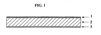
- the film shown in Figure 1 is a co-extruded unit comprising three layers 1, 2, 3.
- the first layer 1 is made from a polyethylene, Exact 0210 from DEX Plastics (Heerlenm, the Netherlands).
- the second layer 2 is made from a blend of COC, Topaz from Ticona. The blend is 70% Topaz 6013 and 30% Topaz 8007.
- the third layer 3 is made from a polypropylene, HP420M from Basell (Hoofdorp, The Netherlands). Extrusion may be carried out by any known process therefor.
- the second layer 2 is sandwiched between the two outer layers 1, 3 and may be formed by extrusion as a thin layer.
- the outer layers 1, 3 allow the film to be more robust and avoid breakage of thin layer 2.
- the film was made by co-extruding the three layers. The extruder was programmed to obtain a total film thickness of 160 ⁇ m with the center core of COC having a thickness of 130 ⁇ m.
- the film may be thermoformed to provide one or more microstructures (not shown).
- the microstructures may be conventional microstructures such as channels, reaction chambers, hybridization chambers, pumps and valves, or may be specially developed for use with the film of the present invention.
- the microstructures which are selected for any particular film will depend on the application of that film.
- the film of Figure 1 is for manufacturing a microfluidic device for use in DNA analysis.
- the film may include a microstructure which consists of a channel with a buffer chamber at either end. Within the buffer chambers are planar electrodes used to separate the DNA with an electrophoresis step.
- the electrodes are carbon electrodes which are screen printed onto the polyethylene layer (the melt seal layer).
- platinum and silver electrode may also be used, for example Ag/AgCl may be used as a reference electrode and Pt as a counter electrode.
- Electrodes must be encapsulated while being exposed at one point externally and at another point internally.
- an electrode By applying an electrode to a melt seal layer it becomes possible to laminate the melt seal layer to another layer or unit including a channel so that the electrode is exposed internally on one side. A hole may then be punched through the melt seal layer on the other side of the electrode so that the electrode is also exposed externally.
- Screen printed carbon electrodes can easily break upon application of heat and pressure during lamination of the films to form the microfluidic device, but this may be avoided by using a co-extruded film having an appropriate thickness of polyethylene and by using an appropriate pressure, temperature, and time for lamination. These variables combined enable the film to be laminated while ensuring that the polyethylene does not flow sufficiently to break the screen printed electrodes.
- FIG. 2 is used to describe the concept of inserting electrodes into the multilayer device.
- the device comprises polypropylene layer 4, COC layer 5, polyethylene layer 6, polyethylene layer 7, COC layer 8 and polypropylene layer 9.
- Area 10 is the hole to allow access to the electrode which is thereby accessible externally.
- Area 11 is a buffer chamber or some internal lumen where voltage is to be applied and finally area 12 is the electrode itself.
- the electrode may be applied by printing, and may consist of a printable conductive material. Such materials are carbon, graphite, and metallic based inks.
- the film of Figure 1 is for manufacturing a microfluidic device for use in a nucleic acid amplification reaction such as the Polymerase Chain Reaction (PCR).
- the film may include microstructures which consist of 1.5 ⁇ l reaction chambers.
- the specific design of the co-extruded polymer was stable for the high temperature requirements of PCR, whilst maintaining good lamination.
- the thin film enabled rapid heat transfer which is very important for conducting the reaction as fast as possible.
- the film properties enables the laminate to be slightly flexible which permitted a very tight fit between the reaction chamber and the heater, thereby facilitating rapid heat transfer.
- the selection of COC as the bulk layer and its excellent optical properties enables quantification with real-time PCR techniques commonly employed on much larger volumes.
- reagents used in PCR can absorb certain polymers and it is therefore important to control the surface properties to improve the reaction yield or even to attain a successful reaction, as explained for example in Liu et al., Lab on Chip, 2006, 769-775 .
- the PCR reaction can be conducted by thermo-cycling with any number of methods. These include but are not limited to thermoelectric heaters, water baths of varying temperatures, thin film heating elements, Infra-red based heating, continuous flow designs and hot air designs. The method of heating can be changed to suit the exact application, but often the basis of the design is to permit rapid heat transfer.
- the PCR reaction chamber was thermoformed using a hemispherical female tool with two channels. One channel was used for loading the reaction chamber with pre-mixed PCR reagents. The other channel was used as an air vent. The tape was then thermo-cycled and following this the PCR reagents were withdrawn and run on a electrophoresis gel for analysis of the PCR amplicons.
- Figure 3 illustrates a third embodiment, in which the device comprises polypropylene layer core polymer layer 14 (in this embodiment COC), polyethylene melt seal layers 15 and 16, bulk layer 17 with the formed channels and reaction chambers, polypropylene layer 18 and finally a hemispherical reaction chamber 19.
- Figure 4 is a photograph of the hemispherical reaction chambers of Figure 3 comprising two channels and loading chambers formed in the co-extruded films.
- Figure 5 shows the PCR reaction chamber 19 with the heater H used to conduct the thermo-cycling.
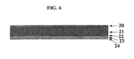
- the film shown in Figure 6 is a co-extruded unit comprising five layers 20, 21, 22, 23, 24.
- the first layer 20 is 15 ⁇ m thick, and is made from a polyethylene, Exact 0210, from DEX Plastics (Heerlenm, The Netherlands).
- the second layer 21 is 100 ⁇ m thick, and is made from the same blend of the COC, Topaz COC, as in the embodiment of Figure 1 .
- the third layer 22 is made from a blend of 80% Exact 0210 and 20% Bynel 47E710, a maleic anhydride grafted polyethylene from Dupont.
- the fourth layer 23 is 15 ⁇ m thick and is made from an ethylene vinyl alcohol (EVOH) Kurraray LCF101 from Mutsui.
- the fifth layer 24 is 15 ⁇ m thick and is made from a maleic anhydride grafted polypropylene 18707 from Arkema.
- the film was made by co-extruding the five layers.
- Layer 23 acts as a gas barrier.
- Layer 22 acts as a tie layer to tie layer 23 to layer 21.
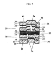
- the film shown in Figure 7 comprises a number of individual co-extruded units, which have been laminated together to form a larger more complex fluid control structure.
- the core elastomer unit 25 comprises three layers 26, 27, 28.
- the two outer layers 26, 28 are both made of a polyethylene, Exact 0210, from DEX Plastomers (Heerlen, The Netherlands).
- the central layer 27 is made of an elastomer, Adflex X100F, from Basell (Hoofddorp, The Netherlands).
- the three extrusion lines are run at appropriate speeds to produce a central layer 27 approximately 30 ⁇ m thick with 3.75 ⁇ m thick outer layers 26, 28.
- Each unit 29, 30 consisting of a layer 31 of COC co-extruded between two layers 32, 33 of the polyethylene, Exact 0210, are laminated to either side of the core elastomer unit 25.
- Each unit 29, 30 contains one or more microstructures in the form of vials 34 which extend through the entire unit 29, 30.
- Two further units 35, 36 each consisting of a layer 37 of COC co-extruded between a layer 38 of the polyethylene, Exact 0210 and a layer 39 of polypropylene, are laminated to either side of the two units 29, 30, and form the outermost units.
- Layers 31 and 37 are generally about 130 ⁇ m thick, layers 32, 33, 38, 39, each 15 ⁇ m thick.
- Three of the units 29, 35, 36 are shaped by thermoforming before lamination to provide a number of microstructures in the form of void areas 40 and channels 41 between the units.
- Lamination is conducted in such a manner that the units are bonded across the entire surface except in the area between and directly proximal to the vials 34, void areas 40 and channels 41.
- the outer units 35, 20 are elevated above their melting temperature so that the polyethylene layer 38 of each outer unit bonds with the adjacent polyethylene layer 32 of the inner units 29, 30.
- the core elastomer unit 25 remains substantially firm and thus maintains its integrity so that the polyethylene layers 26, 28 on the elastomer unit 25 do not flow into the microstructures 18, 23, 24 adjacent to the elastomer unit 25.
- fluid flow through the film may be controlled, for example, the movement upward of elastomer unit 25 (by negative pressure) can allow a fluid in lower channel 41 to pass through vials 34 thereby acting as a valve.
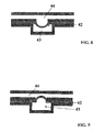
- FIG. 8 and 9 This is illustrated by the film shown in Figures 8 and 9 which comprised layer 42, made of an elastomer, Adflex X100F, from Basell (Hoofddorp, The Netherlands).
- layer 42 made of an elastomer, Adflex X100F, from Basell (Hoofddorp, The Netherlands).
- the density of moleculres at the surface of the elastomer layer may be altered, which has applications in controlling reactions and enhancing the signal to noise ratio.
- a void area 43 On one side of the elastomer layer 42 is a void area 43. On the other side of the elastomer layer 42 is a T-shaped channel 44, which contains biomolecules to be analysed with a surface bound reaction.
- a vacuum is applied to the void area 43, the elastomer layer 42 deforms into the void area 43 as shown in Figure 8 . This changes the density of biomolecules on the surface. This can be used to control the hybridization of nucleic acids, or to control antigen-antibody interactions or biotin-streptavidin complex formation. It can also enhance signal to noise ratio as it reduces the area under investigation and so concentrates the signal.
- pressure is applied to the void area 43, the elastomer layer 42 deforms into the T-shaped channel 44. This results in a larger surface area which will be better at binding the biomolecules in solution.
- Figure 10a is a plan view of a device according to the present invention and a-a represents the position of the cross section as shown in Figure 10b .
- the device comprises microfluidic channel b (hatched area), flexible polymer film c, metering chamber d and pneumatic control chamber e. It is pointed out that the circles in Figure 10b are merely voids generated in microscopy preparation.
Landscapes
- Chemical & Material Sciences (AREA)
- Health & Medical Sciences (AREA)
- Chemical Kinetics & Catalysis (AREA)
- Clinical Laboratory Science (AREA)
- General Health & Medical Sciences (AREA)
- Hematology (AREA)
- Analytical Chemistry (AREA)
- Dispersion Chemistry (AREA)
- Organic Chemistry (AREA)
- Physical Or Chemical Processes And Apparatus (AREA)
- Micromachines (AREA)
- Automatic Analysis And Handling Materials Therefor (AREA)
- Apparatus Associated With Microorganisms And Enzymes (AREA)
- Laminated Bodies (AREA)
Applications Claiming Priority (2)
| Application Number | Priority Date | Filing Date | Title |
|---|---|---|---|
| GB0700822A GB2445738A (en) | 2007-01-16 | 2007-01-16 | Microfluidic device |
| PCT/GB2008/000143 WO2008087405A1 (en) | 2007-01-16 | 2008-01-16 | Microfluidic device |
Publications (2)
| Publication Number | Publication Date |
|---|---|
| EP2114570A1 EP2114570A1 (en) | 2009-11-11 |
| EP2114570B1 true EP2114570B1 (en) | 2013-06-05 |
Family
ID=37810038
Family Applications (1)
| Application Number | Title | Priority Date | Filing Date |
|---|---|---|---|
| EP08701821.4A Active EP2114570B1 (en) | 2007-01-16 | 2008-01-16 | Microfluidic device |
Country Status (6)
| Country | Link |
|---|---|
| US (1) | US20100175999A1 (enExample) |
| EP (1) | EP2114570B1 (enExample) |
| JP (1) | JP5579443B2 (enExample) |
| CN (1) | CN101674888B (enExample) |
| GB (1) | GB2445738A (enExample) |
| WO (1) | WO2008087405A1 (enExample) |
Families Citing this family (39)
| Publication number | Priority date | Publication date | Assignee | Title |
|---|---|---|---|---|
| JP4685329B2 (ja) * | 2000-10-24 | 2011-05-18 | ハンス イエンセン ルブリカトーズ アクティーゼルスカブ | 分配装置 |
| JP4362532B2 (ja) | 2004-04-07 | 2009-11-11 | ウォードロウ パートナーズ エルピー | 生体液を分析する使い捨てチャンバ |
| US8715446B2 (en) * | 2004-10-13 | 2014-05-06 | Rheonix, Inc. | Latent solvent-based microfluidic apparatus, methods, and applications |
| US7731901B2 (en) | 2005-10-19 | 2010-06-08 | Abbott Laboratories | Apparatus and method for performing counts within a biologic fluid sample |
| GB2445739A (en) | 2007-01-16 | 2008-07-23 | Lab901 Ltd | Polymeric laminates containing heat seals |
| DE502008001596D1 (de) * | 2008-06-02 | 2010-12-02 | Boehringer Ingelheim Micropart | Mikrofluidische Folienstruktur zum Dosierren von Flüssigkeiten |
| JP2011030522A (ja) * | 2009-08-04 | 2011-02-17 | Aida Engineering Ltd | マイクロ流体デバイス |
| CN102762289B (zh) | 2009-12-18 | 2016-08-03 | 艾博特健康公司 | 生物流体分析卡盒 |
| CN103097883B (zh) * | 2010-03-09 | 2016-03-02 | 网络百奥有限公司 | 提供样本输入至结果输出处理的单体生物芯片以及制造方法 |
| US8720036B2 (en) | 2010-03-09 | 2014-05-13 | Netbio, Inc. | Unitary biochip providing sample-in to results-out processing and methods of manufacture |
| CN101823686B (zh) * | 2010-04-21 | 2012-07-04 | 大连理工大学 | 一种热塑性聚合物多层微流控芯片封合方法 |
| JP5582049B2 (ja) * | 2010-05-31 | 2014-09-03 | 横河電機株式会社 | 化学処理用カートリッジシステム |
| US9522520B2 (en) | 2010-09-01 | 2016-12-20 | Boehringer Ingelheim Microparts Gmbh | Process for producing a microfluidic apparatus and related laminating devices |
| US9873118B2 (en) | 2010-12-30 | 2018-01-23 | Abbott Point Of Care, Inc. | Biologic fluid analysis cartridge with sample handling portion and analysis chamber portion |
| US20130137144A1 (en) * | 2011-06-08 | 2013-05-30 | Bio-Rad Laboratories, Inc. LSG - GXD Division | Thermal block with built-in thermoelectric elements |
| CN103890590B (zh) | 2011-08-24 | 2016-03-09 | 艾博特健康公司 | 生物流体样品分析盒 |
| WO2013102071A1 (en) * | 2011-12-30 | 2013-07-04 | Abbott Molecular, Inc. | Chemical reaction vessels |
| JP6033959B2 (ja) * | 2013-01-09 | 2016-11-30 | テカン・トレーディング・アクチェンゲゼルシャフトTECAN Trading AG | マイクロ流体システム用使い捨てカートリッジ |
| WO2014116951A2 (en) | 2013-01-24 | 2014-07-31 | Sabic Innovative Plastics Ip B.V. | Polycarbonate microfluidic articles |
| CN104955576A (zh) | 2013-01-24 | 2015-09-30 | 沙特基础全球技术有限公司 | 由聚酯-聚碳酸酯制成的微孔板 |
| EP2948251A1 (en) | 2013-01-24 | 2015-12-02 | SABIC Global Technologies B.V. | Microwell plate made from a polyester-polycarbonate |
| JP6012518B2 (ja) * | 2013-03-21 | 2016-10-25 | 株式会社日立ハイテクノロジーズ | 生化学カートリッジ用温調機構、温調ブロック及び生化学処理装置 |
| US10006444B2 (en) | 2014-04-11 | 2018-06-26 | President And Fellows Of Harvard College | High throughput fabrication of soft machines |
| CN104607256A (zh) * | 2014-12-31 | 2015-05-13 | 北京同方生物芯片技术有限公司 | 等离子体辅助热压键合微流控芯片及其制备方法 |
| US11285478B2 (en) | 2016-04-04 | 2022-03-29 | Combinati Incorporated | Microfluidic siphoning array for nucleic acid quantification |
| US9845499B2 (en) * | 2016-04-04 | 2017-12-19 | Combinati Incorporated | Microfluidic siphoning array for nucleic acid quantification |
| AU2017363076B2 (en) | 2016-11-17 | 2021-04-29 | Combinati Incorporated | Methods and systems for nucleic acid analysis and quantification |
| EP3384987A3 (en) * | 2017-04-03 | 2018-10-24 | CSEM Centre Suisse d'Electronique et de Microtechnique SA - Recherche et Développement | Vessel for performing electrochemical measurements and method for manufacturing such vessel |
| US11253852B2 (en) | 2017-08-17 | 2022-02-22 | Abbott Point Of Care Inc. | Devices, systems, and methods for performing optical assays |
| CN110869746B (zh) | 2017-08-17 | 2023-08-11 | 雅培医护站股份有限公司 | 利用通用电路系统执行光学和电化学测定的技术 |
| US11067526B2 (en) | 2017-08-17 | 2021-07-20 | Abbott Point Of Care Inc. | Devices, systems, and methods for performing optical and electrochemical assays |
| CN107739706B (zh) | 2017-09-26 | 2020-04-14 | 南京岚煜生物科技有限公司 | 主动控制流路的多通量微流控核酸检测芯片及其使用方法 |
| DE102018217907B3 (de) | 2018-10-19 | 2019-12-19 | SpinDiag GmbH | Probenbehälter |
| AU2019397371B2 (en) | 2018-12-10 | 2025-09-18 | Combinati Incorporated | Microfluidic array for sample digitization |
| US12590896B2 (en) | 2019-05-28 | 2026-03-31 | Robert A. Levine | Apparatus and method for transferring and analyzing suspended particles in a liquid sample |
| WO2020261086A1 (en) | 2019-06-28 | 2020-12-30 | 3M Innovative Properties Company | Articles having conformal layers and methods of making same |
| CN112569881B (zh) * | 2020-07-24 | 2021-07-20 | 苏州恒瑞宏远医疗科技有限公司 | 一种反应装置及其加工方法 |
| DE102020202767B3 (de) * | 2020-03-04 | 2021-05-27 | Hahn-Schickard-Gesellschaft für angewandte Forschung e.V. | Herstellung eines Verbunds aus Polymersubstraten und gesiegelte mikrofluidische Kartusche |
| CN116368213A (zh) | 2020-09-28 | 2023-06-30 | 康比纳蒂股份有限公司 | 用于样品处理的装置和方法 |
Citations (4)
| Publication number | Priority date | Publication date | Assignee | Title |
|---|---|---|---|---|
| US20030118804A1 (en) * | 2001-05-02 | 2003-06-26 | 3M Innovative Properties Company | Sample processing device with resealable process chamber |
| WO2004061418A2 (en) * | 2002-12-26 | 2004-07-22 | Meso Scale Technologies, Llc. | Assay cartridges and methods of using the same |
| WO2006081558A2 (en) * | 2005-01-28 | 2006-08-03 | Duke University | Apparatuses and methods for manipulating droplets on a printed circuit board |
| WO2007002480A2 (en) * | 2005-06-24 | 2007-01-04 | Board Of Regents, The University Of Texas System | Systems and methods including self-contained cartridges with detection systems and fluid delivery systems |
Family Cites Families (22)
| Publication number | Priority date | Publication date | Assignee | Title |
|---|---|---|---|---|
| US4333968A (en) * | 1980-01-25 | 1982-06-08 | Mobil Oil Corporation | Thermoplastic packaging films with improved heat-seal characteristics |
| WO1994026414A1 (en) * | 1993-05-17 | 1994-11-24 | Syntex (U.S.A.) Inc. | Reaction container for specific binding assays and method for its use |
| US5500071A (en) * | 1994-10-19 | 1996-03-19 | Hewlett-Packard Company | Miniaturized planar columns in novel support media for liquid phase analysis |
| US5658413A (en) * | 1994-10-19 | 1997-08-19 | Hewlett-Packard Company | Miniaturized planar columns in novel support media for liquid phase analysis |
| US5525405A (en) * | 1994-12-14 | 1996-06-11 | E. I. Du Pont De Nemours And Company | Adhesiveless aromatic polyimide laminate |
| JP3839524B2 (ja) * | 1995-06-07 | 2006-11-01 | アジレント・テクノロジーズ・インク | 小型化全分析システム |
| US5932799A (en) * | 1997-07-21 | 1999-08-03 | Ysi Incorporated | Microfluidic analyzer module |
| US6375871B1 (en) * | 1998-06-18 | 2002-04-23 | 3M Innovative Properties Company | Methods of manufacturing microfluidic articles |
| US6627159B1 (en) * | 2000-06-28 | 2003-09-30 | 3M Innovative Properties Company | Centrifugal filling of sample processing devices |
| WO2002081934A2 (en) * | 2001-04-03 | 2002-10-17 | Micronics, Inc. | Pneumatic valve interface for use in microfluidic structures |
| EP1390624A1 (en) * | 2001-04-25 | 2004-02-25 | President And Fellows Of Harvard College | Fluidic switches and method for controlling flow in fluidic systems |
| JP2003028877A (ja) * | 2001-07-17 | 2003-01-29 | Sekisui Chem Co Ltd | 反応チップ用担体及び反応チップ |
| GB0128350D0 (en) * | 2001-11-27 | 2002-01-16 | Lab901 Ltd | Non-rigid apparatus for microfluidic applications |
| JP2003220330A (ja) * | 2002-01-31 | 2003-08-05 | Asahi Kasei Corp | 透明ポリマーチップ |
| AR038590A1 (es) * | 2002-02-22 | 2005-01-19 | Clopay Plastic Prod Co | Hoja laminada de pelicula y metodos para su fabricacion |
| US20040101657A1 (en) * | 2002-08-19 | 2004-05-27 | Moles Donald R. | Method of microfluidic construction using composite polymer films |
| US7431888B2 (en) * | 2002-09-20 | 2008-10-07 | The Regents Of The University Of California | Photoinitiated grafting of porous polymer monoliths and thermoplastic polymers for microfluidic devices |
| CA2515075C (en) * | 2003-02-05 | 2012-10-02 | Iquum, Inc. | Sample processing |
| CA2521171C (en) * | 2003-04-03 | 2013-05-28 | Fluidigm Corp. | Microfluidic devices and methods of using same |
| JP2006076246A (ja) * | 2004-09-13 | 2006-03-23 | Rohm Co Ltd | 基板の貼り合わせ方法、その貼り合わせ方法を用いたチップ形成方法及びチップ |
| JP4547216B2 (ja) * | 2004-09-17 | 2010-09-22 | 東洋製罐株式会社 | ガスバリアー性及び層間接着性に優れた多層容器 |
| US20060272716A1 (en) * | 2005-05-12 | 2006-12-07 | University Of Washington | Method of adhesiveless lamination of polymer films into microfluidic networks with high dimensional fidelity |
-
2007
- 2007-01-16 GB GB0700822A patent/GB2445738A/en not_active Withdrawn
-
2008
- 2008-01-16 EP EP08701821.4A patent/EP2114570B1/en active Active
- 2008-01-16 US US12/523,500 patent/US20100175999A1/en not_active Abandoned
- 2008-01-16 JP JP2009545993A patent/JP5579443B2/ja active Active
- 2008-01-16 CN CN2008800065615A patent/CN101674888B/zh active Active
- 2008-01-16 WO PCT/GB2008/000143 patent/WO2008087405A1/en not_active Ceased
Patent Citations (4)
| Publication number | Priority date | Publication date | Assignee | Title |
|---|---|---|---|---|
| US20030118804A1 (en) * | 2001-05-02 | 2003-06-26 | 3M Innovative Properties Company | Sample processing device with resealable process chamber |
| WO2004061418A2 (en) * | 2002-12-26 | 2004-07-22 | Meso Scale Technologies, Llc. | Assay cartridges and methods of using the same |
| WO2006081558A2 (en) * | 2005-01-28 | 2006-08-03 | Duke University | Apparatuses and methods for manipulating droplets on a printed circuit board |
| WO2007002480A2 (en) * | 2005-06-24 | 2007-01-04 | Board Of Regents, The University Of Texas System | Systems and methods including self-contained cartridges with detection systems and fluid delivery systems |
Also Published As
| Publication number | Publication date |
|---|---|
| GB0700822D0 (en) | 2007-02-21 |
| CN101674888B (zh) | 2012-06-13 |
| JP5579443B2 (ja) | 2014-08-27 |
| GB2445738A (en) | 2008-07-23 |
| CN101674888A (zh) | 2010-03-17 |
| JP2010515924A (ja) | 2010-05-13 |
| WO2008087405A1 (en) | 2008-07-24 |
| EP2114570A1 (en) | 2009-11-11 |
| US20100175999A1 (en) | 2010-07-15 |
Similar Documents
| Publication | Publication Date | Title |
|---|---|---|
| EP2114570B1 (en) | Microfluidic device | |
| US9283561B2 (en) | Liquid channel device and production method therefor | |
| JP6498125B2 (ja) | 流体回路および関連する製造方法 | |
| US6527003B1 (en) | Micro valve actuator | |
| US8137624B2 (en) | Method and apparatus for attaching a fluid cell to a planar substrate | |
| US20030118804A1 (en) | Sample processing device with resealable process chamber | |
| WO2008037485A1 (en) | Disposable fluidic device having a reversibly closable fluid valve and a system to operate such a device | |
| WO2003050035A2 (en) | Adhesiveless microfluidic device fabrication | |
| US9283562B2 (en) | Liquid channel device and production method therefor | |
| JP2012524268A (ja) | マイクロ流体デバイスをマクロ流体デバイスに接続するための装置及び方法 | |
| JP5948248B2 (ja) | マイクロチップ、及び、マイクロチップの製造方法 | |
| KR20220088758A (ko) | 분석 장치 및 제조 방법 | |
| JP2008008880A (ja) | プラスチック製マイクロチップ、及びその製造方法、並びにそれを利用したバイオチップ又はマイクロ分析チップ | |
| KR101853602B1 (ko) | 단층 구조의 생체 분자 농축 장치 및 그 제조방법 | |
| JP2008304352A (ja) | 流路デバイス用基板の接合方法および流路デバイス | |
| JPWO2010016370A1 (ja) | マイクロチップ、マイクロチップの製造方法及びマイクロチップの製造装置 | |
| EP1572364A1 (en) | Sample processing device with resealable process chamber | |
| KR100779083B1 (ko) | 플라스틱 미세가열 시스템, 그 미세가열 시스템을 이용한랩온어칩, 및 그 미세가열 시스템의 제조방법 | |
| EP4140582A1 (en) | Method for sealing microfluidic structures by means of a hybrid-foil membrane | |
| Czurratis | Long-term on-chip storage and release of liquids for pressure driven Lab-on-a-Chip platforms | |
| KR20150050770A (ko) | 다층 형상을 포함하는 미세 구조의 제조 방법 및 그 활용. | |
| Kong | Fully Integrated Molecular Diagnostic CD Platform Based on Thermal Control |
Legal Events
| Date | Code | Title | Description |
|---|---|---|---|
| PUAI | Public reference made under article 153(3) epc to a published international application that has entered the european phase |
Free format text: ORIGINAL CODE: 0009012 |
|
| 17P | Request for examination filed |
Effective date: 20090720 |
|
| AK | Designated contracting states |
Kind code of ref document: A1 Designated state(s): AT BE BG CH CY CZ DE DK EE ES FI FR GB GR HR HU IE IS IT LI LT LU LV MC MT NL NO PL PT RO SE SI SK TR |
|
| 17Q | First examination report despatched |
Effective date: 20091120 |
|
| DAX | Request for extension of the european patent (deleted) | ||
| RIN1 | Information on inventor provided before grant (corrected) |
Inventor name: THOMSON, DAVID Inventor name: POLWART, STUART Inventor name: MACNAMARA, KEN Inventor name: BARLOW, DAVID |
|
| GRAP | Despatch of communication of intention to grant a patent |
Free format text: ORIGINAL CODE: EPIDOSNIGR1 |
|
| GRAS | Grant fee paid |
Free format text: ORIGINAL CODE: EPIDOSNIGR3 |
|
| GRAA | (expected) grant |
Free format text: ORIGINAL CODE: 0009210 |
|
| AK | Designated contracting states |
Kind code of ref document: B1 Designated state(s): AT BE BG CH CY CZ DE DK EE ES FI FR GB GR HR HU IE IS IT LI LT LU LV MC MT NL NO PL PT RO SE SI SK TR |
|
| REG | Reference to a national code |
Ref country code: GB Ref legal event code: FG4D |
|
| REG | Reference to a national code |
Ref country code: CH Ref legal event code: EP Ref country code: CH Ref legal event code: PUE Owner name: AGILENT TECHNOLOGIES, INC., US Free format text: FORMER OWNER: LAB 901 LIMITED, GB |
|
| REG | Reference to a national code |
Ref country code: AT Ref legal event code: REF Ref document number: 615312 Country of ref document: AT Kind code of ref document: T Effective date: 20130615 |
|
| REG | Reference to a national code |
Ref country code: IE Ref legal event code: FG4D |
|
| REG | Reference to a national code |
Ref country code: DE Ref legal event code: R096 Ref document number: 602008025133 Country of ref document: DE Effective date: 20130801 |
|
| REG | Reference to a national code |
Ref country code: FR Ref legal event code: TP Owner name: AGILENT TECHNOLOGIES, INC., US Effective date: 20130719 |
|
| RAP2 | Party data changed (patent owner data changed or rights of a patent transferred) |
Owner name: AGILENT TECHNOLOGIES, INC. |
|
| REG | Reference to a national code |
Ref country code: GB Ref legal event code: 732E Free format text: REGISTERED BETWEEN 20130815 AND 20130821 |
|
| REG | Reference to a national code |
Ref country code: CH Ref legal event code: NV Representative=s name: RIEDERER HASLER AND PARTNER PATENTANWAELTE AG, LI |
|
| REG | Reference to a national code |
Ref country code: DE Ref legal event code: R081 Ref document number: 602008025133 Country of ref document: DE Owner name: AGILENT TECHNOLOGIES INC., SANTA CLARA, US Free format text: FORMER OWNER: LAB 901 LIMITED, MIDLOTHIAN, GB Effective date: 20130808 Ref country code: DE Ref legal event code: R081 Ref document number: 602008025133 Country of ref document: DE Owner name: AGILENT TECHNOLOGIES INC., US Free format text: FORMER OWNER: LAB 901 LIMITED, MIDLOTHIAN, GB Effective date: 20130808 |
|
| REG | Reference to a national code |
Ref country code: AT Ref legal event code: MK05 Ref document number: 615312 Country of ref document: AT Kind code of ref document: T Effective date: 20130605 |
|
| PG25 | Lapsed in a contracting state [announced via postgrant information from national office to epo] |
Ref country code: GR Free format text: LAPSE BECAUSE OF FAILURE TO SUBMIT A TRANSLATION OF THE DESCRIPTION OR TO PAY THE FEE WITHIN THE PRESCRIBED TIME-LIMIT Effective date: 20130906 Ref country code: NO Free format text: LAPSE BECAUSE OF FAILURE TO SUBMIT A TRANSLATION OF THE DESCRIPTION OR TO PAY THE FEE WITHIN THE PRESCRIBED TIME-LIMIT Effective date: 20130905 Ref country code: FI Free format text: LAPSE BECAUSE OF FAILURE TO SUBMIT A TRANSLATION OF THE DESCRIPTION OR TO PAY THE FEE WITHIN THE PRESCRIBED TIME-LIMIT Effective date: 20130605 Ref country code: AT Free format text: LAPSE BECAUSE OF FAILURE TO SUBMIT A TRANSLATION OF THE DESCRIPTION OR TO PAY THE FEE WITHIN THE PRESCRIBED TIME-LIMIT Effective date: 20130605 Ref country code: SE Free format text: LAPSE BECAUSE OF FAILURE TO SUBMIT A TRANSLATION OF THE DESCRIPTION OR TO PAY THE FEE WITHIN THE PRESCRIBED TIME-LIMIT Effective date: 20130605 Ref country code: ES Free format text: LAPSE BECAUSE OF FAILURE TO SUBMIT A TRANSLATION OF THE DESCRIPTION OR TO PAY THE FEE WITHIN THE PRESCRIBED TIME-LIMIT Effective date: 20130916 Ref country code: SI Free format text: LAPSE BECAUSE OF FAILURE TO SUBMIT A TRANSLATION OF THE DESCRIPTION OR TO PAY THE FEE WITHIN THE PRESCRIBED TIME-LIMIT Effective date: 20130605 Ref country code: LT Free format text: LAPSE BECAUSE OF FAILURE TO SUBMIT A TRANSLATION OF THE DESCRIPTION OR TO PAY THE FEE WITHIN THE PRESCRIBED TIME-LIMIT Effective date: 20130605 |
|
| REG | Reference to a national code |
Ref country code: NL Ref legal event code: VDEP Effective date: 20130605 |
|
| REG | Reference to a national code |
Ref country code: LT Ref legal event code: MG4D |
|
| PG25 | Lapsed in a contracting state [announced via postgrant information from national office to epo] |
Ref country code: PL Free format text: LAPSE BECAUSE OF FAILURE TO SUBMIT A TRANSLATION OF THE DESCRIPTION OR TO PAY THE FEE WITHIN THE PRESCRIBED TIME-LIMIT Effective date: 20130605 Ref country code: BG Free format text: LAPSE BECAUSE OF FAILURE TO SUBMIT A TRANSLATION OF THE DESCRIPTION OR TO PAY THE FEE WITHIN THE PRESCRIBED TIME-LIMIT Effective date: 20130905 Ref country code: HR Free format text: LAPSE BECAUSE OF FAILURE TO SUBMIT A TRANSLATION OF THE DESCRIPTION OR TO PAY THE FEE WITHIN THE PRESCRIBED TIME-LIMIT Effective date: 20130605 |
|
| PG25 | Lapsed in a contracting state [announced via postgrant information from national office to epo] |
Ref country code: LV Free format text: LAPSE BECAUSE OF FAILURE TO SUBMIT A TRANSLATION OF THE DESCRIPTION OR TO PAY THE FEE WITHIN THE PRESCRIBED TIME-LIMIT Effective date: 20130605 |
|
| PG25 | Lapsed in a contracting state [announced via postgrant information from national office to epo] |
Ref country code: PT Free format text: LAPSE BECAUSE OF FAILURE TO SUBMIT A TRANSLATION OF THE DESCRIPTION OR TO PAY THE FEE WITHIN THE PRESCRIBED TIME-LIMIT Effective date: 20131007 Ref country code: EE Free format text: LAPSE BECAUSE OF FAILURE TO SUBMIT A TRANSLATION OF THE DESCRIPTION OR TO PAY THE FEE WITHIN THE PRESCRIBED TIME-LIMIT Effective date: 20130605 Ref country code: BE Free format text: LAPSE BECAUSE OF FAILURE TO SUBMIT A TRANSLATION OF THE DESCRIPTION OR TO PAY THE FEE WITHIN THE PRESCRIBED TIME-LIMIT Effective date: 20130605 Ref country code: CZ Free format text: LAPSE BECAUSE OF FAILURE TO SUBMIT A TRANSLATION OF THE DESCRIPTION OR TO PAY THE FEE WITHIN THE PRESCRIBED TIME-LIMIT Effective date: 20130605 Ref country code: SK Free format text: LAPSE BECAUSE OF FAILURE TO SUBMIT A TRANSLATION OF THE DESCRIPTION OR TO PAY THE FEE WITHIN THE PRESCRIBED TIME-LIMIT Effective date: 20130605 Ref country code: IS Free format text: LAPSE BECAUSE OF FAILURE TO SUBMIT A TRANSLATION OF THE DESCRIPTION OR TO PAY THE FEE WITHIN THE PRESCRIBED TIME-LIMIT Effective date: 20131005 |
|
| PG25 | Lapsed in a contracting state [announced via postgrant information from national office to epo] |
Ref country code: NL Free format text: LAPSE BECAUSE OF FAILURE TO SUBMIT A TRANSLATION OF THE DESCRIPTION OR TO PAY THE FEE WITHIN THE PRESCRIBED TIME-LIMIT Effective date: 20130605 Ref country code: RO Free format text: LAPSE BECAUSE OF FAILURE TO SUBMIT A TRANSLATION OF THE DESCRIPTION OR TO PAY THE FEE WITHIN THE PRESCRIBED TIME-LIMIT Effective date: 20130605 |
|
| PLBE | No opposition filed within time limit |
Free format text: ORIGINAL CODE: 0009261 |
|
| STAA | Information on the status of an ep patent application or granted ep patent |
Free format text: STATUS: NO OPPOSITION FILED WITHIN TIME LIMIT |
|
| PG25 | Lapsed in a contracting state [announced via postgrant information from national office to epo] |
Ref country code: DK Free format text: LAPSE BECAUSE OF FAILURE TO SUBMIT A TRANSLATION OF THE DESCRIPTION OR TO PAY THE FEE WITHIN THE PRESCRIBED TIME-LIMIT Effective date: 20130605 |
|
| 26N | No opposition filed |
Effective date: 20140306 |
|
| PG25 | Lapsed in a contracting state [announced via postgrant information from national office to epo] |
Ref country code: IT Free format text: LAPSE BECAUSE OF FAILURE TO SUBMIT A TRANSLATION OF THE DESCRIPTION OR TO PAY THE FEE WITHIN THE PRESCRIBED TIME-LIMIT Effective date: 20130605 |
|
| REG | Reference to a national code |
Ref country code: DE Ref legal event code: R097 Ref document number: 602008025133 Country of ref document: DE Effective date: 20140306 |
|
| PG25 | Lapsed in a contracting state [announced via postgrant information from national office to epo] |
Ref country code: MC Free format text: LAPSE BECAUSE OF FAILURE TO SUBMIT A TRANSLATION OF THE DESCRIPTION OR TO PAY THE FEE WITHIN THE PRESCRIBED TIME-LIMIT Effective date: 20130605 Ref country code: LU Free format text: LAPSE BECAUSE OF FAILURE TO SUBMIT A TRANSLATION OF THE DESCRIPTION OR TO PAY THE FEE WITHIN THE PRESCRIBED TIME-LIMIT Effective date: 20140116 |
|
| REG | Reference to a national code |
Ref country code: IE Ref legal event code: MM4A |
|
| PG25 | Lapsed in a contracting state [announced via postgrant information from national office to epo] |
Ref country code: IE Free format text: LAPSE BECAUSE OF NON-PAYMENT OF DUE FEES Effective date: 20140116 |
|
| REG | Reference to a national code |
Ref country code: FR Ref legal event code: PLFP Year of fee payment: 9 |
|
| PG25 | Lapsed in a contracting state [announced via postgrant information from national office to epo] |
Ref country code: MT Free format text: LAPSE BECAUSE OF FAILURE TO SUBMIT A TRANSLATION OF THE DESCRIPTION OR TO PAY THE FEE WITHIN THE PRESCRIBED TIME-LIMIT Effective date: 20130605 |
|
| PG25 | Lapsed in a contracting state [announced via postgrant information from national office to epo] |
Ref country code: CY Free format text: LAPSE BECAUSE OF FAILURE TO SUBMIT A TRANSLATION OF THE DESCRIPTION OR TO PAY THE FEE WITHIN THE PRESCRIBED TIME-LIMIT Effective date: 20130605 |
|
| PG25 | Lapsed in a contracting state [announced via postgrant information from national office to epo] |
Ref country code: HU Free format text: LAPSE BECAUSE OF FAILURE TO SUBMIT A TRANSLATION OF THE DESCRIPTION OR TO PAY THE FEE WITHIN THE PRESCRIBED TIME-LIMIT; INVALID AB INITIO Effective date: 20080116 Ref country code: TR Free format text: LAPSE BECAUSE OF FAILURE TO SUBMIT A TRANSLATION OF THE DESCRIPTION OR TO PAY THE FEE WITHIN THE PRESCRIBED TIME-LIMIT Effective date: 20130605 |
|
| REG | Reference to a national code |
Ref country code: FR Ref legal event code: PLFP Year of fee payment: 10 |
|
| REG | Reference to a national code |
Ref country code: FR Ref legal event code: PLFP Year of fee payment: 11 |
|
| P01 | Opt-out of the competence of the unified patent court (upc) registered |
Effective date: 20230527 |
|
| PGFP | Annual fee paid to national office [announced via postgrant information from national office to epo] |
Ref country code: GB Payment date: 20251127 Year of fee payment: 19 |
|
| PGFP | Annual fee paid to national office [announced via postgrant information from national office to epo] |
Ref country code: FR Payment date: 20251124 Year of fee payment: 19 |
|
| REG | Reference to a national code |
Ref country code: CH Ref legal event code: U11 Free format text: ST27 STATUS EVENT CODE: U-0-0-U10-U11 (AS PROVIDED BY THE NATIONAL OFFICE) Effective date: 20260201 |
|
| PGFP | Annual fee paid to national office [announced via postgrant information from national office to epo] |
Ref country code: DE Payment date: 20251119 Year of fee payment: 19 |
|
| PGFP | Annual fee paid to national office [announced via postgrant information from national office to epo] |
Ref country code: CH Payment date: 20260201 Year of fee payment: 19 |