EP2113432B1 - Essuie-glace, en particulier pour véhicules automobiles - Google Patents
Essuie-glace, en particulier pour véhicules automobiles Download PDFInfo
- Publication number
- EP2113432B1 EP2113432B1 EP08008320.7A EP08008320A EP2113432B1 EP 2113432 B1 EP2113432 B1 EP 2113432B1 EP 08008320 A EP08008320 A EP 08008320A EP 2113432 B1 EP2113432 B1 EP 2113432B1
- Authority
- EP
- European Patent Office
- Prior art keywords
- wiper arm
- wiper
- side walls
- linking part
- connecting part
- Prior art date
- Legal status (The legal status is an assumption and is not a legal conclusion. Google has not performed a legal analysis and makes no representation as to the accuracy of the status listed.)
- Active
Links
Images


Classifications
-
- B—PERFORMING OPERATIONS; TRANSPORTING
- B60—VEHICLES IN GENERAL
- B60S—SERVICING, CLEANING, REPAIRING, SUPPORTING, LIFTING, OR MANOEUVRING OF VEHICLES, NOT OTHERWISE PROVIDED FOR
- B60S1/00—Cleaning of vehicles
- B60S1/02—Cleaning windscreens, windows or optical devices
- B60S1/04—Wipers or the like, e.g. scrapers
- B60S1/32—Wipers or the like, e.g. scrapers characterised by constructional features of wiper blade arms or blades
- B60S1/38—Wiper blades
- B60S1/3848—Flat-type wiper blade, i.e. without harness
- B60S1/3849—Connectors therefor; Connection to wiper arm; Attached to blade
- B60S1/3851—Mounting of connector to blade assembly
- B60S1/3856—Gripping the blade
-
- B—PERFORMING OPERATIONS; TRANSPORTING
- B60—VEHICLES IN GENERAL
- B60S—SERVICING, CLEANING, REPAIRING, SUPPORTING, LIFTING, OR MANOEUVRING OF VEHICLES, NOT OTHERWISE PROVIDED FOR
- B60S1/00—Cleaning of vehicles
- B60S1/02—Cleaning windscreens, windows or optical devices
- B60S1/04—Wipers or the like, e.g. scrapers
- B60S1/32—Wipers or the like, e.g. scrapers characterised by constructional features of wiper blade arms or blades
- B60S1/38—Wiper blades
- B60S1/3806—Means, or measures taken, for influencing the aerodynamic quality of the wiper blades
- B60S1/381—Spoilers mounted on the squeegee or on the vertebra
-
- B—PERFORMING OPERATIONS; TRANSPORTING
- B60—VEHICLES IN GENERAL
- B60S—SERVICING, CLEANING, REPAIRING, SUPPORTING, LIFTING, OR MANOEUVRING OF VEHICLES, NOT OTHERWISE PROVIDED FOR
- B60S1/00—Cleaning of vehicles
- B60S1/02—Cleaning windscreens, windows or optical devices
- B60S1/04—Wipers or the like, e.g. scrapers
- B60S1/32—Wipers or the like, e.g. scrapers characterised by constructional features of wiper blade arms or blades
- B60S1/38—Wiper blades
- B60S1/3848—Flat-type wiper blade, i.e. without harness
- B60S1/3849—Connectors therefor; Connection to wiper arm; Attached to blade
- B60S1/386—Connectors therefor; Connection to wiper arm; Attached to blade made in two halves
-
- B—PERFORMING OPERATIONS; TRANSPORTING
- B60—VEHICLES IN GENERAL
- B60S—SERVICING, CLEANING, REPAIRING, SUPPORTING, LIFTING, OR MANOEUVRING OF VEHICLES, NOT OTHERWISE PROVIDED FOR
- B60S1/00—Cleaning of vehicles
- B60S1/02—Cleaning windscreens, windows or optical devices
- B60S1/04—Wipers or the like, e.g. scrapers
- B60S1/32—Wipers or the like, e.g. scrapers characterised by constructional features of wiper blade arms or blades
- B60S1/38—Wiper blades
- B60S1/3848—Flat-type wiper blade, i.e. without harness
- B60S1/3849—Connectors therefor; Connection to wiper arm; Attached to blade
- B60S1/387—Connectors therefor; Connection to wiper arm; Attached to blade the connector being suitable for receiving different types of adapter
-
- B—PERFORMING OPERATIONS; TRANSPORTING
- B60—VEHICLES IN GENERAL
- B60S—SERVICING, CLEANING, REPAIRING, SUPPORTING, LIFTING, OR MANOEUVRING OF VEHICLES, NOT OTHERWISE PROVIDED FOR
- B60S1/00—Cleaning of vehicles
- B60S1/02—Cleaning windscreens, windows or optical devices
- B60S1/04—Wipers or the like, e.g. scrapers
- B60S1/32—Wipers or the like, e.g. scrapers characterised by constructional features of wiper blade arms or blades
- B60S1/40—Connections between blades and arms
- B60S1/4038—Connections between blades and arms for arms provided with a channel-shaped end
- B60S1/4045—Connections between blades and arms for arms provided with a channel-shaped end comprising a detachable intermediate element mounted on the channel-shaped end
- B60S1/4048—Connections between blades and arms for arms provided with a channel-shaped end comprising a detachable intermediate element mounted on the channel-shaped end the element being provided with retention means co-operating with the channel-shaped end of the arm
- B60S2001/4051—Connections between blades and arms for arms provided with a channel-shaped end comprising a detachable intermediate element mounted on the channel-shaped end the element being provided with retention means co-operating with the channel-shaped end of the arm the intermediate element engaging the side walls of the arm
-
- B—PERFORMING OPERATIONS; TRANSPORTING
- B60—VEHICLES IN GENERAL
- B60S—SERVICING, CLEANING, REPAIRING, SUPPORTING, LIFTING, OR MANOEUVRING OF VEHICLES, NOT OTHERWISE PROVIDED FOR
- B60S1/00—Cleaning of vehicles
- B60S1/02—Cleaning windscreens, windows or optical devices
- B60S1/04—Wipers or the like, e.g. scrapers
- B60S1/32—Wipers or the like, e.g. scrapers characterised by constructional features of wiper blade arms or blades
- B60S1/40—Connections between blades and arms
- B60S1/4038—Connections between blades and arms for arms provided with a channel-shaped end
- B60S1/4045—Connections between blades and arms for arms provided with a channel-shaped end comprising a detachable intermediate element mounted on the channel-shaped end
- B60S1/4048—Connections between blades and arms for arms provided with a channel-shaped end comprising a detachable intermediate element mounted on the channel-shaped end the element being provided with retention means co-operating with the channel-shaped end of the arm
- B60S2001/4054—Connections between blades and arms for arms provided with a channel-shaped end comprising a detachable intermediate element mounted on the channel-shaped end the element being provided with retention means co-operating with the channel-shaped end of the arm the intermediate element engaging the back part of the arm
-
- B—PERFORMING OPERATIONS; TRANSPORTING
- B60—VEHICLES IN GENERAL
- B60S—SERVICING, CLEANING, REPAIRING, SUPPORTING, LIFTING, OR MANOEUVRING OF VEHICLES, NOT OTHERWISE PROVIDED FOR
- B60S1/00—Cleaning of vehicles
- B60S1/02—Cleaning windscreens, windows or optical devices
- B60S1/04—Wipers or the like, e.g. scrapers
- B60S1/32—Wipers or the like, e.g. scrapers characterised by constructional features of wiper blade arms or blades
- B60S1/40—Connections between blades and arms
- B60S1/4038—Connections between blades and arms for arms provided with a channel-shaped end
- B60S2001/4061—Connections between blades and arms for arms provided with a channel-shaped end covered by a removable cover mounted on the blade
Definitions
- the present invention relates to a windscreen wiper, in particular for a windscreen of a motor vehicle, having a drivable wiper arm and a flat wiper blade connected thereto in accordance with the preamble of claim 1 (see, for example, FIGS DE 103 47 637 A1 ).
- Devices for connecting a wiper blade to a wiper arm of the first type according to the features in the preamble of claim 1 are known from EP 186 88 60 B1 and from the EP 167 32 64 A0 (the WO 2005 039 944 A1 accordingly).
- the wiper arm at its connectable to the wiper blade end in each case the same construction.
- This consists of a substantially U-shaped cross-sectional profile with a top wall and two side walls, at the bottom, in the mounted state to the wiper blade facing ends in each case an inwardly bent bar is formed.
- an opening is provided in the top wall of the wiper arm end.
- the lower strips of Wischerarmendes act in the above EP 186 88 60 B1 and the EP 167 32 64 A0 each as Schmidtraststoff.
- the wiper arm end is snapped in the vertical direction on a hinged to the wiper blade connector.
- laterally projecting spring tongues are formed laterally on the connecting piece, which are pressed laterally inwards when placing the Wischerarmendes through the strips of Wischerarmendes before they finally engage in the final assembly position behind the strips or lock with them.
- a device for connecting a wiper blade with a wiper arm of the second type according to claim 1 and some additional features of the dependent claim 7 is shown in EP 156 53 59 B1 known.
- the connectable to the wiper blade end of the wiper arm is U-shaped and has a top wall and two side walls.
- V-shaped undercuts are provided on the side walls of the wiper arm end, whose oblique boundary edges enclose an acute angle with the longitudinal axis of the wiper arm.
- edges of these undercuts act as locking edges, which lock in the assembly of wiper blade with wiper arm on lateral locking tongues of a floating mounted on the wiper blade connecting element.
- a tongue-shaped portion is formed at the tip of the wiper arm end which is inserted into an opening in the top wall of the connecting element, this tongue-shaped insertion portion rests in final assembly position against the inside of the top wall of the connecting element.
- Locking elements Due to the method of assembly, in which the wiper blade is first attached and then pivoted about this point, lateral locking elements on the connecting element of the wiper blade are indispensable. Locking elements, however, have, as already noted in the prior art described above, the disadvantage that they are subject as elastic elements during assembly and disassembly regularly a mechanical load and thus a possible damage.
- the object of the present invention is to improve the connection of a flat wiper blade with two wiper arm end constructions mentioned in the preamble of claim 1 and claim 8 to the effect that the assembly of flat wiper blade is achieved with two wiper arm ends without lateral elastic latching elements, but instead positive insertion or insertion and still done quickly and easily.
- the advantage achieved by the invention is that a pivotally arranged on the central connecting part of the flat wiper blade connection part is used, which, unlike the known from the prior art connectors or elements no longer or no longer exclusively via a locking or Clip connection is connected to the two known Wischerarmenden.
- the lateral spring tongues have been replaced by solid, not to be bent during assembly molding.
- Another advantage is that the spring tongue in the top wall of the connecting part in the present invention in a defined manner when horizontally inserted into the opening of the Wischerarmendes. A possible non-clash of spring tongue and opening during vertical latching is not possible here.
- the flat wiper blade or the connecting part of the flat wiper blade must be pivoted to the wiper arm in the longitudinal direction, that the outer pins of the connecting part in the undercuts of the Side walls of the wiper arm can be introduced first. Only then is the flat wiper blade pivoted against the wiper arm until it reaches a longitudinal axis-parallel position about the journal axis, which is now also the assembly pivot axis. Finally, the hood part is placed on the connecting part to secure, wherein the hood part simultaneously clamps the wiper arm end against the connecting part and thus also the flat wiper blade.
- a further advantage is that a universal connecting part, which combines both the features of claim 1 and the features of claims 7 and 8, can be used.
- the user thus has the opportunity to mount a flat wiper blade of the same type on the two different wiper arm types according to the preamble of claim 1 and the features of claims 7 and 8 using a common connecting part.
- the expansion of the range of use for the flat wiper blade lowers the manufacturing costs for the same, which is reflected in the final purchaser in lower acquisition costs.
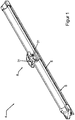
- a flat wiper blade 4 is shown, which according to the present invention by connection to a wiper arm 2a, 2b, either the in Fig. 6 or the in Fig. 11 shown end construction may become a windshield wiper 1 according to the invention.
- Flat wiper blades have long been known from the prior art and have as an elastic element at least one band-shaped elongated spring rail 6, which serves as a support means for the underlying arranged wiper rubber 5, which in turn rests in the operating state on the disc to be cleaned.
- the flat wiper blade 4 At the side facing away from the squeegee 5, the flat wiper blade 4 has an aerodynamically shaped spoiler cover.
- connection part 8 Central on Flat wiper blade 4 is arranged a connection part 8, which has a box-shaped, open-top structure of two end and two side walls and in whose two side walls each aligned through holes 31 are introduced.
- the flat wiper blade 4 is shown only by the connecting part 8, that is, the elongated facial expressions of the flat wiper blade 4 with spring rail 6, wiper blade 5, etc. has been omitted for clarity in the illustrations.
- this is purely a graphic tool and does not mean that in the assembly steps shown below, the connection part 8 would be separated from the flat wiper blade 4.
- a clamp-shaped recess is provided for the usually formed in the form of a spring rail 6 support means.
- the spring rail 6 guided there is then inseparable, for example by soldering or by riveting, connected to the connection part 8.
- the connecting means 7 of the flat wiper blade 4 for connecting the flat wiper blade 4 to the coupling sections of the two wiper arm ends 3a, 3b are formed by this connecting part 8 as a permanent component of the flat wiper blade 4 and an additional connecting part 9, which is detachably attached to this connecting part 8 and in Fig. 2 and Fig. 3 is first shown in dissolved from the connector 8 and then mounted in the connector part 8 state.
- the connecting part 9 has in cross-section substantially a U-shaped structure of two side walls 17 and a top wall 10, wherein in the main direction of the connecting part 9 and thus also the flat wiper blade 4 aligned side walls 17 clearly, in about 4 to 5 times, longer are as the transverse to the main extension direction facing top wall 10.
- the length of the side walls 17 of the connecting part 9 is also clear, approximately twice, as large as the side wall lengths of the connecting part eighth
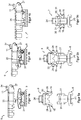
- FIGS. 4a to 4c and 5a to 5c is shown in longitudinal and front view, as the connecting part 9 is connected to the connecting part 8.
- the connecting part 9 according to the FIGS. 4a and 5a positioned to the connecting part 8, that the open bottom side of the cross-sectionally U-shaped connecting part 9 to the connecting part 8 has.
- the connecting part has 9 between the side walls 17 an inner width which approximately corresponds to the outer width of the connecting part 8.
- the connecting part 9 has on its two side walls 17 in each case an inwardly pointing pin 30 which is aligned with one another.
- the inner pins 30 initially cause the side walls 17 of the connecting part 9 to bend outwards. Since the side walls 17 are connected to each other only by the top wall 10 and a thin web at one longitudinal end, this elasticity is given. Finally, the inner pins 30 of the connecting part 9 then fall into the bearing bores 31 of the connecting part 8, and a firm, but rotatable connection between the connecting part 9 and the connecting part 8 is achieved.
- the side walls 17 have to be bent in a simple manner only slightly outwards in order to disengage the inner pins 30 and bearing bores 31. Then, the connecting part 9 can be released again by pushing up from the connection part 8.
- Fig. 6 shows the construction of a according to the preamble of claim 1 with the flat wiper blade 4 Fig. 1 Wischerarmendes first type 3a to be coupled rotatably.
- the wiper arm end 3a on various coupling means which are required in the assembled state with corresponding negative feedback means of the connecting part 9 to achieve a solid, but always releasable connection of the connecting part 9 and wiper arm 2a.
- the connecting part 9 is in turn rotatably connected to the flat wiper blade 4, thus a solid but oscillating compensatory movements in the operating state permitting connection of flat wiper blade 4 and wiper arm 2a is achieved.
- the wiper arm end 3a is similar to the connecting part 9 in its cross section substantially U-shaped and consists of a top wall 13a and two side walls 14a.
- As a coupling means in the top wall 13a an approximately square opening 12 and at the lower ends of the side walls 14a each an approximately at right angles inwardly facing bar 15 is provided.
- FIGS. 7a to 7d The assembled connecting means 7 of the flat wiper blade 4 will now be according to the FIGS. 7a to 7d connected to the wiper arm 2a.
- the connecting part 9 is lower in its height than the connecting part 8.
- Fig. 7a and 7b becomes clear, even for the first assembly steps for connection to the wiper arm end 3a required.
- the flat wiper blade 4 is aligned along the longitudinal axis parallel to the wiper arm 2a-longitudinal axis, the open underside of the wiper arm end 3a facing the connecting means 7 of the flat wiper blade 4.
- the connecting part 9 is now inserted into the open end face 16 of the wiper arm end 3a.
- a spring tongue 11 is formed, which expands obliquely upwards out of the top wall level and has a nose-shaped elevation 34 at its end.
- This spring tongue 11 Due to this spring tongue 11, it is not possible to insert the connecting part 9 directly in its longitudinal axis with the wiper arm 2a - longitudinal axis aligned, since in this case the spring tongue 11 would collide against the top wall 13a of the wiper arm end 3a. To prevent this, either, as in the FIGS. 7a and 7b shown, only the connecting part 9 or the entire flat wiper blade 4 together with the connecting part 9 to the wiper arm 2a inclined so that between the two longitudinal axes, a mounting angle ⁇ is formed.
- This mounting angle ⁇ is in the range of 0 ° to 90 °, preferably in the range of 0 ° to 45 °.
- the connecting part 9 can now be inserted into the wiper arm end 3a.
- Fig. 7c After the obliquely oriented insertion, the connecting part 9 is pivoted back again into a position in which the longitudinal axes of the connecting part 9 and wiper arm end 3a are aligned with one another. In this pivoting back the spring tongue 11 is bent by the abutment of the locking lug 34 of the connecting part 9 on the inside of the top wall 13 a of the wiper arm end 3 a down into the interior of the connecting part 9. Now the connecting part 9 can be inserted in the longitudinal direction.
- the connecting part 9 at the lower end of its two side walls 17 at right angles to the outside facing slide strips 18, the on are serving as a guide strips 15 of the wiper arm end 3a slidably mounted, so that the connecting part 9 can be inserted horizontally on these guide rails 15.
- the measured between the end faces 28 of the two outer pins 27 width of the connecting part 9 corresponds to the width between the inner sides of the two side walls 14a of the Wischerarmendes 3a, so that even during insertion, the end faces 28 of the two outer pins 27 on the inner sides of the two side walls 14a of Wischerarmendes 3a abut.
- the connecting part 9 of the flat wiper blade 4 is pushed so far until the latch 34 of the integrally formed on the top wall 10 of the connecting part 9 spring tongue 11 engages in the opening 12 of the top wall 13 a of the wiper arm end 3 a.
- the locking lug 34 also has approximately the same dimensions as the Wischerarmö réelle 12, so that the outer sides of the latching lug 34 are supported against the inner sides of the opening 12, whereby a positionally stable fixation of wiper arm 2a and connecting part 9 and thus also flat wiper blade 4 is reached.
- the two lateral sliding strips 18 of the connecting part 9 each have a downwardly molded base 25, which are matched in their longitudinal position to the longitudinal position of the locking lug 34, that in the assembled state, the base 25 respectively on the lateral guide rails 15 of the wiper arm end 3a abut the front side.
- Fig. 8 With the final assembly position after Fig. 8 is an operational connection of wiper arm 3a and flat wiper blade 4 before. However, it is visible that after insertion still a large part, about half the length of the connecting part 9, still remains outside the wiper arm end 3a. This is the windshield wiper 1 a length and width offset in the coupling region of wiper arm 2a and flat wiper blade 4 noted. This is on the one hand unaesthetic and aerodynamically not favorable on the other hand, because at these offset edges easily undesirable turbulence may arise, which would be reflected in driving in an increase in flow noise.
- a Hood-shaped cover part 19 which is also U-shaped in cross section and is composed of a top wall 20, two side walls 21 and an end wall 22, snapped onto the exposed end of the connecting part 9.
- the hood part 19 comprises with its four walls 20, 21, 22, the exposed walls 10, 17 of the connecting part, wherein the outer geometry of the open longitudinal end of the hood part 19 is adapted to the end edges of the wiper arm end 3a, that the hood part 19 is a flush termination of Wiperarmendes 3a forms.
- To accomplish the Aufrastinstitut have hood part 19 and connecting part 9 cooperating locking means 23, 24 with each other.
- the hood part 19 has on the inside of its side walls 21 for this purpose two vertically extending, spaced-apart locking tongues 23.
- the connecting part 9 in turn has on the outside of its side walls 17 three equally spaced, vertically extending locking grooves 24, the interval distance corresponds to the distance of the hood part 19 - locking tongues 23.
- the hood part 19 can thus be latched onto the two wiper arm end 3a facing the two longitudinally viewed from the wiper arm end 3a or remote from the wiper arm end 3a of the connecting part 9.
- the latching takes place on the two locking grooves 24 facing the wiper arm end 3a, so that a final assembly of the wiper arm 2a and the flat wiper blade 4 accordingly Fig. 10 is reached.
- the side walls 21 of the hood part 19 are bent by contact of the locking tongues 23 with the outer sides of the connecting part 19 when placed first outwards until form-fitting final formations on the locking tongues 23 and locking grooves 24 engage in final assembly position and the side walls 21 of the hood part 19 then back to plan the side walls 17 of the connecting part 9 abut.
- the latching lug 34 of the connecting part 9 can be pressed quasi as an actuating button, then to dismantle the flat wiper blade 4 this just in reverse order of the mounting sequence of the FIGS. 7a to 7d to push out.
- the hood part 19 has on its end wall 22 has a V-shaped, symmetrical slot 36, whose contour approximately the outer contour of the spoiler cover of the flat wiper blade 4 from Fig. 1 equivalent. Through this slot 36 allows that provided with the hood part 19 connecting part 9 continues, at least limited, can rotate relative to the flat wiper blade 4.
- FIG. 11 are shown in perspective view the already described connecting means 7 of the flat wiper blade 4 and a wiper arm of the second type 2b according to claims 7 and 8.
- a wiper arm 2b has at its end 3b also coupling means for connection from above, as a so-called "top-lock" closure, on a flat wiper blade 4.
- the wiper arm 2b at its end 3b has a substantially U-shaped cross-section.
- the type of coupling agent differs.
- This wiper arm carries on its top wall 13b no opening, but has in its two side walls 14b each have a V-shaped, rounded undercut 29.
- the wiper arm 2b at its front end a tongue-shaped extension 32 on.
- the connecting part 9 in turn has, for cooperation with the coupling means of the wiper arm end 3b, corresponding countercoupling means which, in connection with the aforementioned wiper arm 2a (FIG. Fig. 6 ) have exercised according to claim 1 still another function or partly no function at all.
- the negative feedback means of the connecting part 9, which make the connection with the in Fig. 6 Ensure wiper arm 2a shown in claim 1, in the connection described in the following with the in Fig. 11 illustrated wiper arm 2b according to claim 8 also partly a different or partially no function.
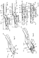
- FIGS. 12a to 12c show the assembly process for connecting the flat wiper blade 4 to the wiper arm 2b.
- the connecting means 7 of the flat wiper blade 4 are aligned with the wiper arm end 3 b so that the open underside of the wiper arm end 3 b faces these connecting means 7.
- the connecting part 9 is inclined with respect to the wiper arm 2b - longitudinal axis, that the formed on the outer sides of the two side walls 17 of the connecting part 9 pin 27 can be inserted into the undercuts 29 on the side walls 14b of the wiper arm end 3b.
- the oblique inclination necessary for the assembly by the angle ⁇ between connecting part 9 and wiper arm 2b longitudinal axis can be provided either by rotation of the connecting part 9 about the axis of rotation 30, 31 to the connecting part 8 or by rotation of the entire flat wiper blade 4.
- the mounting angle ⁇ is in the range of 0 ° to 90 °, preferably in the range of 0 ° to 20 °.
- Fig. 13 represents the pre-assembly position between wiper arm 2b and flat wiper blade 4 in half-section through the wiper arm end 3b and the connecting means 7 of the Flat wiper blade 4 dar.
- the spring tongue 11 is bent on the top wall 10 of the connecting part 9 by the abutment of the locking lug 34 on the inside of the top wall 13 b of the wiper arm end 3 b inwardly, without it still exerts a Verrastungsfunktion.
- Fig. 14 again shows a perspective view of the connection between the wiper arm 2b and connecting part 9 of the flat wiper blade 4 in a pre-assembly position.
- the wiper arm of the second type 2b has at its end 3b a smaller inner width than the previously described wiper arm of the first type 2a Fig. 6 according to the preamble of claim 1 on. Therefore, the lateral outer edges 18 of the connecting part 9 are no longer now, as to the FIGS. 7a to 7d described lying as a slide strips in the interior of the wiper arm end 3a, but now run outwardly flush with the side walls 14b of the wiper arm end 3b.
- the side walls 14b of the wiper arm end 3b lie with their undersides almost flush on the outer strips 18 of the connecting part 9, whereby an advantageous optical impression is achieved.
- FIGS. 9a to 9c already described hood part 19 on the wiper arm 3b facing away from the longitudinal end of the connecting part 9 according to the FIGS. 15a and 15b snapped.
- the top wall 20 of the hood part 19 is no longer only, as in the wiper arm 2a from the FIGS. 9a to 9c described, on the top wall 10 of the connecting part 9, but also supports with the underside of its top wall 20 and the tongue-shaped end portion 32 of the wiper arm end 3b from above.
- the hood part 19 has on the underside of its top wall 20 a survey 35, which is approximately trapezoidal in cross section, and in the partial sectional view Fig. 15b partly hidden by a latching tongue 23 can be seen.
- the elevation 35 on the hood part 19 - inside has a form-complementary shape to the tongue-shaped end portion 32 of the wiper arm 2b, so that when snapped hood part 19 elevation 35 and tongue-shaped end portion 32 abut each other flat.
- the connection of hood part 19 and connecting part 9 is done as described above by latching hood part locking tongues 23 in connecting part locking grooves 24.
- the wiper arm 2b in the form of its tongue-shaped end portion 32 against the connecting part 9 and herewith the flat wiper blade 4 is securely held down by the hood part 19, and there is now a reliable connection of flat wiper blade 4 and wiper arm 2b.
- the hood part 19 must first be removed, which is done manually simply by widening its side walls 21 and subsequently pushing the hood part 19 upwards. Then, in reverse order of the FIGS. 12a to 12c the flat wiper blade 4 can be released from the wiper arm end 3b by pivoting out.
- FIGS. 15a and 15b happens the latching of hood part 19 on connecting part 9 in a relative longitudinal position to each other, in which both latching tongues 23 of the hood part 19 engage in the two wiper arm 3b remote from the locking grooves 24 of the connecting part 9.
- Out Fig. 15b It is clear that between the end wall 22 of the hood part 19 and the hood part 19 covered end face of the connecting part 9 is a free distance, while the free end face of the top wall 20 of the hood part 19 on the end face of the top wall 13b of the wiper arm 3b is flush.
- the two "top-lock" connections described here ie connections between a wiper blade and a wiper arm arranged above it, take place between a common flat wiper blade 4 and two different wiper arm constructions 2 a, 2 b. It is for a common, universal connector 9 is used. Through the use of the universal connection part 9, the application range of a flat wiper blade 4 according to Fig. 1 can also be extended by mounting it now with two different wiper arms 2a, 2b is possible.
Claims (15)
- Essuie-glace (1), en particulier pour une vitre d'un véhicule automobile, avec un bras d'essuie-glace motorisable d'un premier type (2a) ou un bras d'essuie-glace motorisable d'un deuxième type (2b), et avec un balai d'essuie-glace plat (4) qui peut être disposé à l'extrémité libre (3a ; 3b) du bras d'essuie-glace du premier type (2a) ou du bras d'essuie-glace du deuxième type (2b) et qui comprend une lame caoutchouc (5), un moyen porteur (6), soutenant la lame caoutchouc (5) et réalisé de préférence sous la forme d'une barrette élastique oblongue du genre bande, et des moyens de liaison (7) pour rattacher le balai d'essuie-glace plat (4) à l'extrémité libre (3a ; 3b) du bras d'essuie-glace du premier type (2a) ou du bras d'essuie-glace du deuxième type (2b), sachant que ces moyens de liaison (7) sont constitués d'une pièce de raccordement (8) disposée fixement sur le moyen porteur (6) et d'une pièce de liaison (9) disposée à rotation sur la pièce de raccordement (8), sachant que cette pièce de liaison (9) possède un profil de section essentiellement en forme de U avec deux parois latérales (27) et porte, sur sa paroi de recouvrement (10) tournée vers le bras d'essuie-glace du premier type (2a), une languette flexible (11) qui, dans l'état monté, s'engage dans une ouverture (12) dans une paroi de recouvrement (13a) de l'extrémité (3a) du bras d'essuie-glace du premier type, sachant que l'extrémité (3a) du bras d'essuie-glace du premier type possède un profil de section essentiellement en forme de U et sachant qu'un rail de guidage respectif (15), courbé vers l'intérieur, est formé aux extrémités inférieures de ses deux parois latérales (14a), caractérisé en ce que les deux parois latérales (17) de la pièce de liaison (9) présentent un biais d'introduction respectif (26) aux extrémités longitudinales tournées vers le bras d'essuie-glace du premier type (2a), et en ce que, pour le montage du balai d'essuie-glace plat (4) avec le bras d'essuie-glace du premier type (2a), la pièce de liaison (9) du balai d'essuie-glace plat (4) peut être introduite et rentrée par coulissement en direction longitudinale dans le côté frontal ouvert (16) de l'extrémité (3a) du bras d'essuie-glace du premier type sous un angle de montage α formé entre l'axe longitudinal de la pièce de liaison (9) et l'axe longitudinal du bras d'essuie-glace (2a), par le fait que la pièce de liaison (9) est, par deux glissières (18) dirigées vers l'extérieur sur les deux parois latérales (17), montée à coulissement sur les deux rails de guidage (15) à l'intérieur de l'extrémité (3a) du bras d'essuie-glace du premier type, et peut être rentrée par coulissement jusqu'à ce que la languette flexible (11) s'enclenche dans l'ouverture (12).
- Essuie-glace selon la revendication 1, caractérisé en ce qu'une pièce formant capot (19), qui possède un profil de section essentiellement en forme de U et qui est constituée d'une paroi de recouvrement (20), de deux parois latérales (21) et d'une paroi frontale (22), peut être enclenchée par le dessus sur la pièce de liaison (9) au moyen d'une liaison par enclenchement amovible.
- Essuie-glace selon la revendication 2, caractérisé en ce que la liaison par enclenchement est réalisée par des languettes d'enclenchement (23) formées sur le côté intérieur de la pièce formant capot (19) et des rainures d'enclenchement (24) formées sur le côté extérieur de la pièce de liaison (9).
- Essuie-glace selon l'une des revendications précédentes, caractérisé en ce qu'une embase (25) respective dirigée vers le bas est formée sur les deux glissières (18) de la pièce de liaison (9), embase qui, dans l'état monté, s'applique respectivement contre le rail de guidage (15) de l'extrémité (3a) du bras d'essuie-glace du premier type.
- Essuie-glace selon l'une des revendications précédentes, caractérisé en ce que l'angle de montage α, formé entre les axes longitudinaux de la pièce de liaison (9) et du bras d'essuie-glace (2a) pour l'introduction de la pièce de liaison (9) du balai d'essuie-glace plat (4) dans l'extrémité (3a) du bras d'essuie-glace du premier type, est compris entre 0° et 90°, de préférence entre 0° et 45°.
- Essuie-glace selon l'une des revendications précédentes, caractérisé en ce qu'un tenon extérieur (27) respectif est formé sur les deux parois latérales (17) de la pièce de liaison (9), tenon dont les faces frontales (28), dans l'état rentré par coulissement, s'appliquent contre le côté intérieur des parois latérales (14a) de l'extrémité (3a) du bras d'essuie-glace du premier type, sachant que ces tenons extérieurs (27) facilitent, en tant que moyens de centrage transversal, l'introduction des moyens de liaison (7) du balai d'essuie-glace plat (4) dans l'extrémité (3a) du bras d'essuie-glace du premier type.
- Essuie-glace (1) selon la revendication 1, caractérisé en ce que l'extrémité (3b) du bras d'essuie-glace du deuxième type, réalisée en forme de U en coupe transversale, comprend une paroi de recouvrement (13b) et deux parois latérales (14b) et ces deux parois latérales (14b) présentent sur leur bord inférieur une contre-dépouille respective (29) en forme de V, et en ce qu'un tenon extérieur (27) respectif est formé sur les côtés extérieurs des deux parois latérales (17) de la pièce de liaison (9), tenons qui peuvent être respectivement introduits dans les contre-dépouilles (29) en forme de V des parois latérales (14b) de l'extrémité (3b) du bras d'essuie-glace du deuxième type, de sorte que ces tenons extérieurs (27) forment, dans l'état monté, un axe de pivotement entre le balai d'essuie-glace plat (4) et le bras d'essuie-glace du deuxième type (2b).
- Essuie-glace selon la revendication 7, caractérisé en ce qu'une pièce formant capot (19), réalisée en forme de U en coupe transversale, peut être posée sur la pièce de liaison (9) et cette pièce formant capot (19) maintient alors en même temps le bras d'essuie-glace du deuxième type (2b) pressé sur le balai d'essuie-glace plat (4), par le fait que le côté inférieur de la paroi de recouvrement (20) de la pièce formant capot (19) repose au moins partiellement sur la face supérieure de l'extrémité (3b) du bras d'essuie-glace du deuxième type.
- Essuie-glace selon la revendication 8, caractérisé en ce que la pièce formant capot (19) est constituée d'une paroi de recouvrement (20), de deux parois latérales (21) et d'une paroi frontale (22), et peut être enclenchée par le dessus sur la pièce de liaison (9) au moyen d'une liaison par enclenchement amovible.
- Essuie-glace selon la revendication 9, caractérisé en ce que la liaison par enclenchement est réalisée par des languettes d'enclenchement (23) formées sur le côté intérieur de la pièce formant capot (19) et des rainures d'enclenchement (24) formées sur le côté extérieur de la pièce de liaison (9).
- Essuie-glace selon l'une des revendications 8 à 10, caractérisé en ce que la pièce formant capot (19) présente, sur le côté inférieur de sa paroi de recouvrement (20), un bossage (35) qui coopère avec une partie complémentaire (32) de l'extrémité (3b) du bras d'essuie-glace du deuxième type.
- Essuie-glace selon l'une des revendications 8 à 11, caractérisé en ce que, pour l'engagement des tenons extérieurs (27) de la pièce de liaison (9) dans les contre-dépouilles (29) en forme de V des parois latérales (14b) de l'extrémité (3b) du bras d'essuie-glace du deuxième type, la pièce de liaison (9) est pivotée en direction du bras d'essuie-glace du deuxième type (2b) de telle sorte qu'un angle de montage β de 0° à 90°, de préférence de 0° à 20°, est présent entre leurs deux axes longitudinaux.
- Essuie-glace selon la revendication 3 ou 10, caractérisé en ce que la pièce de liaison (9) présente trois rainures d'enclenchement verticales équidistantes respectives (24) sur les côtés extérieurs des parois latérales (17) et la pièce formant capot (19) présente deux languettes d'enclenchement verticales équidistantes respectives (23) sur les côtés intérieurs des parois latérales (21), de sorte que la liaison entre la pièce formant capot (19) et la pièce de liaison (9) peut avoir lieu dans deux positions longitudinales relatives d'une pièce par rapport à l'autre.
- Essuie-glace selon l'une des revendications précédentes, caractérisé en ce que deux tenons intérieurs (30), mutuellement alignés en direction transversale, sont formés sur les côtés intérieurs des parois latérales (17) de la pièce de liaison (9), tenons qui, dans l'état monté, sont respectivement introduits dans un perçage de palier (31) de la pièce de raccordement (8), de sorte qu'une liaison pivotante est réalisée entre la pièce de raccordement (8) et la pièce de liaison (9).
- Essuie-glace selon l'une des revendications précédentes, caractérisé en ce que la pièce formant capot (19) présente sur sa paroi frontale (22) une fente (36), afin de permettre une rotation limitée de la pièce de liaison (9) pourvue de la pièce formant capot (19) par rapport au balai d'essuie-glace plat (4).
Priority Applications (2)
| Application Number | Priority Date | Filing Date | Title |
|---|---|---|---|
| EP08008320.7A EP2113432B2 (fr) | 2008-05-02 | 2008-05-02 | Essuie-glace, en particulier pour véhicules automobiles |
| BRPI0901324-5A BRPI0901324B1 (pt) | 2008-05-02 | 2009-04-24 | Limpador de pára-brisa |
Applications Claiming Priority (1)
| Application Number | Priority Date | Filing Date | Title |
|---|---|---|---|
| EP08008320.7A EP2113432B2 (fr) | 2008-05-02 | 2008-05-02 | Essuie-glace, en particulier pour véhicules automobiles |
Publications (3)
| Publication Number | Publication Date |
|---|---|
| EP2113432A1 EP2113432A1 (fr) | 2009-11-04 |
| EP2113432B1 true EP2113432B1 (fr) | 2017-11-15 |
| EP2113432B2 EP2113432B2 (fr) | 2021-03-24 |
Family
ID=39832780
Family Applications (1)
| Application Number | Title | Priority Date | Filing Date |
|---|---|---|---|
| EP08008320.7A Active EP2113432B2 (fr) | 2008-05-02 | 2008-05-02 | Essuie-glace, en particulier pour véhicules automobiles |
Country Status (2)
| Country | Link |
|---|---|
| EP (1) | EP2113432B2 (fr) |
| BR (1) | BRPI0901324B1 (fr) |
Families Citing this family (23)
| Publication number | Priority date | Publication date | Assignee | Title |
|---|---|---|---|---|
| KR101766939B1 (ko) | 2010-06-23 | 2017-08-23 | 페더랄-모굴 에스.아. | 차창용 와이퍼 장치 |
| TWM404153U (en) | 2010-09-07 | 2011-05-21 | Zhi-Ming Yang | Joining structure applicable for windshield wiper |
| US9457768B2 (en) | 2011-04-21 | 2016-10-04 | Pylon Manufacturing Corp. | Vortex damping wiper blade |
| US9174609B2 (en) | 2011-04-21 | 2015-11-03 | Pylon Manufacturing Corp. | Wiper blade with cover |
| MX345011B (es) | 2011-07-28 | 2017-01-11 | Pylon Mfg Corp | Adaptador, conector y conjunto de limpiaparabrisas. |
| US8806700B2 (en) | 2011-07-29 | 2014-08-19 | Pylon Manufacturing Corporation | Wiper blade connector |
| US9108595B2 (en) | 2011-07-29 | 2015-08-18 | Pylon Manufacturing Corporation | Windshield wiper connector |
| US20130219649A1 (en) | 2012-02-24 | 2013-08-29 | Pylon Manufacturing Corp. | Wiper blade |
| CA2865292C (fr) | 2012-02-24 | 2018-03-13 | Pylon Manufacturing Corp. | Balai d'essuie-glaces |
| FR2994146B1 (fr) * | 2012-08-02 | 2015-07-03 | Valeo Systemes Dessuyage | Systeme de connexion entre un bras d'essuyage et un balai d'essuyage |
| US10829092B2 (en) | 2012-09-24 | 2020-11-10 | Pylon Manufacturing Corp. | Wiper blade with modular mounting base |
| US10166951B2 (en) | 2013-03-15 | 2019-01-01 | Pylon Manufacturing Corp. | Windshield wiper connector |
| CN104228775B (zh) * | 2013-06-14 | 2017-12-15 | 博世汽车部件(长沙)有限公司 | 雨刮器系统 |
| US20160250999A1 (en) * | 2013-08-06 | 2016-09-01 | Daimler Ag | Apparatus for connecting a wiper blade to a wiper arm of a motor vehicle and wiper blade |
| US9505380B2 (en) | 2014-03-07 | 2016-11-29 | Pylon Manufacturing Corp. | Windshield wiper connector and assembly |
| USD777079S1 (en) | 2014-10-03 | 2017-01-24 | Pylon Manufacturing Corp. | Wiper blade frame |
| CN107107875B (zh) * | 2014-10-17 | 2019-11-26 | 费德罗-莫格尔汽车配件有限责任公司 | 挡风玻璃雨刮装置 |
| WO2016061461A1 (fr) * | 2014-10-17 | 2016-04-21 | Federal-Mogul Motorparts Corporation | Dispositif d'essuie-glace |
| US20160107616A1 (en) * | 2014-10-17 | 2016-04-21 | Federal-Mogul Motorparts Corporation | Windscreen wiper device |
| BR102015007588B1 (pt) | 2015-04-06 | 2022-04-26 | Dyna Indústria E Comércio Ltda | Conexão de palheta de limpador de pára-brisa para multiplos tipos de braços |
| US10363905B2 (en) | 2015-10-26 | 2019-07-30 | Pylon Manufacturing Corp. | Wiper blade |
| FR3043043B1 (fr) * | 2015-11-04 | 2018-10-12 | Valeo Systemes D'essuyage | Adaptateur pour balai d’essuyage de vitre, et dispositif de raccordement correspondant entre un balai et un bras d’entrainement |
| US11040705B2 (en) | 2016-05-19 | 2021-06-22 | Pylon Manufacturing Corp. | Windshield wiper connector |
Citations (15)
| Publication number | Priority date | Publication date | Assignee | Title |
|---|---|---|---|---|
| FR2759048A1 (fr) | 1997-01-31 | 1998-08-07 | Valeo Systemes Dessuyage | Essuie-glace de vehicule automobile comportant des moyens perfectionnes d'articulation d'un balai d'essuie-glace sur un bras d'essuie-glace |
| FR2788027A1 (fr) | 1998-12-30 | 2000-07-07 | Valeo Systemes Dessuyage | Essuie-glace de vehicule automobile comportant des moyens perfectionnes d'articulation du balai sur le bras d'essuie-glace |
| WO2002040328A1 (fr) | 2000-11-18 | 2002-05-23 | Robert Bosch Gmbh | Dispositif de fixation liberable d'un essuie-glace pour le nettoyage de vitres, en particulier de vehicules a moteur, sur un bras d'essuie-glace |
| WO2004098962A1 (fr) | 2003-05-09 | 2004-11-18 | Volkswagen Aktiengesellschaft | Dispositif de raccordement servant a monter une raclette sur un bras d'essuie-glace d'un systeme d'essuie-glace |
| DE10347637A1 (de) | 2003-10-09 | 2005-05-12 | Bosch Gmbh Robert | Vorrichtung zum Verbinden eines Wischblatts mit einem Wischerarm sowie ein Wischblatt, einen Wischerarm und ein entsprechendes Verbindungsstück |
| WO2005082691A1 (fr) | 2004-02-26 | 2005-09-09 | Federal-Mogul S.A. | Dispositif de type essuie-glace |
| WO2006013152A1 (fr) | 2004-08-03 | 2006-02-09 | Federal-Mogul S.A. | Essuie-glace de pare-brise |
| WO2006087271A1 (fr) | 2005-02-17 | 2006-08-24 | Federal-Mogul S.A. | Vehicule dote d'au moins deux dispositifs d'essuie-glace |
| WO2006106006A1 (fr) | 2005-04-08 | 2006-10-12 | Robert Bosch Gmbh | Dispositif pour relier de façon articulee un balai d'essuie-glace a un bras d'essuie-glace |
| WO2006128763A1 (fr) | 2005-06-01 | 2006-12-07 | Robert Bosch Gmbh | Dispositif de connexion articulee d'un balai d'essuie-glace a un bras d'essuie-glace |
| KR100692371B1 (ko) | 2006-02-23 | 2007-03-12 | 주식회사 캄코 | 와이퍼 연결장치의 커넥터 |
| KR100692369B1 (ko) | 2006-02-23 | 2007-03-12 | 주식회사 캄코 | 와이퍼 연결장치의 와이퍼 암 연결체 |
| FR2890925A1 (fr) | 2005-09-21 | 2007-03-23 | Valeo Systemes Dessuyage | Connecteur de montage et d'articulation d'un balai d'essuyage sur l'extremite d'un bras d'entrainement |
| KR100725988B1 (ko) | 2006-02-23 | 2007-06-08 | 주식회사 캄코 | 와이퍼 연결장치 |
| EP1795406A1 (fr) | 2005-12-09 | 2007-06-13 | Federal-Mogul S.A. | Dispositif d'essuie-glace |
Family Cites Families (2)
| Publication number | Priority date | Publication date | Assignee | Title |
|---|---|---|---|---|
| AU2003288140A1 (en) | 2002-11-26 | 2004-06-18 | Valeo Wischersysteme Gmbh | Device for detachably linking a wiper blade with a driven wiper arm |
| DE10362341B3 (de) * | 2002-11-26 | 2023-02-09 | Valeo Wischersysteme Gmbh | Wischerblatt |
-
2008
- 2008-05-02 EP EP08008320.7A patent/EP2113432B2/fr active Active
-
2009
- 2009-04-24 BR BRPI0901324-5A patent/BRPI0901324B1/pt active IP Right Grant
Patent Citations (15)
| Publication number | Priority date | Publication date | Assignee | Title |
|---|---|---|---|---|
| FR2759048A1 (fr) | 1997-01-31 | 1998-08-07 | Valeo Systemes Dessuyage | Essuie-glace de vehicule automobile comportant des moyens perfectionnes d'articulation d'un balai d'essuie-glace sur un bras d'essuie-glace |
| FR2788027A1 (fr) | 1998-12-30 | 2000-07-07 | Valeo Systemes Dessuyage | Essuie-glace de vehicule automobile comportant des moyens perfectionnes d'articulation du balai sur le bras d'essuie-glace |
| WO2002040328A1 (fr) | 2000-11-18 | 2002-05-23 | Robert Bosch Gmbh | Dispositif de fixation liberable d'un essuie-glace pour le nettoyage de vitres, en particulier de vehicules a moteur, sur un bras d'essuie-glace |
| WO2004098962A1 (fr) | 2003-05-09 | 2004-11-18 | Volkswagen Aktiengesellschaft | Dispositif de raccordement servant a monter une raclette sur un bras d'essuie-glace d'un systeme d'essuie-glace |
| DE10347637A1 (de) | 2003-10-09 | 2005-05-12 | Bosch Gmbh Robert | Vorrichtung zum Verbinden eines Wischblatts mit einem Wischerarm sowie ein Wischblatt, einen Wischerarm und ein entsprechendes Verbindungsstück |
| WO2005082691A1 (fr) | 2004-02-26 | 2005-09-09 | Federal-Mogul S.A. | Dispositif de type essuie-glace |
| WO2006013152A1 (fr) | 2004-08-03 | 2006-02-09 | Federal-Mogul S.A. | Essuie-glace de pare-brise |
| WO2006087271A1 (fr) | 2005-02-17 | 2006-08-24 | Federal-Mogul S.A. | Vehicule dote d'au moins deux dispositifs d'essuie-glace |
| WO2006106006A1 (fr) | 2005-04-08 | 2006-10-12 | Robert Bosch Gmbh | Dispositif pour relier de façon articulee un balai d'essuie-glace a un bras d'essuie-glace |
| WO2006128763A1 (fr) | 2005-06-01 | 2006-12-07 | Robert Bosch Gmbh | Dispositif de connexion articulee d'un balai d'essuie-glace a un bras d'essuie-glace |
| FR2890925A1 (fr) | 2005-09-21 | 2007-03-23 | Valeo Systemes Dessuyage | Connecteur de montage et d'articulation d'un balai d'essuyage sur l'extremite d'un bras d'entrainement |
| EP1795406A1 (fr) | 2005-12-09 | 2007-06-13 | Federal-Mogul S.A. | Dispositif d'essuie-glace |
| KR100692371B1 (ko) | 2006-02-23 | 2007-03-12 | 주식회사 캄코 | 와이퍼 연결장치의 커넥터 |
| KR100692369B1 (ko) | 2006-02-23 | 2007-03-12 | 주식회사 캄코 | 와이퍼 연결장치의 와이퍼 암 연결체 |
| KR100725988B1 (ko) | 2006-02-23 | 2007-06-08 | 주식회사 캄코 | 와이퍼 연결장치 |
Also Published As
| Publication number | Publication date |
|---|---|
| EP2113432B2 (fr) | 2021-03-24 |
| BRPI0901324A2 (pt) | 2010-04-06 |
| BRPI0901324B1 (pt) | 2020-08-11 |
| EP2113432A1 (fr) | 2009-11-04 |
Similar Documents
| Publication | Publication Date | Title |
|---|---|---|
| EP2113432B1 (fr) | Essuie-glace, en particulier pour véhicules automobiles | |
| DE102008011449B4 (de) | Wischarm/Wischblattverbindung | |
| EP2259954B1 (fr) | Raclette d essuie-glace | |
| EP1732792B1 (fr) | Raclette d'essuie-glace | |
| EP2736775B1 (fr) | Dispositif de raccordement pour la liaison articulée d'une raclette à un porte-balais et un adaptateur | |
| DE4439109B4 (de) | Mit einer Windleitvorrichtung komplettierbares Wischblatt | |
| EP2614203B1 (fr) | Deviateur pour cable pour lève-vitre à câble | |
| DE102009002764A1 (de) | Anschlussvorrichtung zum gelenkigen Verbinden eines mit einem Wischarm fest verbundenen Verbindungselement | |
| EP2321160A1 (fr) | Dispositif de liaison articulée entre un balai d essuie-glace et un bras d essuie-glace | |
| EP2331372B1 (fr) | Raclette d'essuie-glace et assemblage realise entre un bras et une raclette d'un essuie-glace | |
| DE10043427B4 (de) | Wischvorrichtung | |
| EP2179901B1 (fr) | Dispositif de raccordement pour la liaison articulée d'une lame d'essuyage conçue sous la forme d'une barre plate avec un bras d'essuyage | |
| DE202006020521U1 (de) | Schienenverbindungsanordnung | |
| DE4032427B4 (de) | Verbindungsvorrichtung für ein Wischblatt, insbesondere an einem Kraftfahrzeug | |
| DE2839587A1 (de) | Wischblatt, insbesondere fue scheibenreinigungsanlagen in kraftfahrzeugen | |
| EP2108552B1 (fr) | Essuie-glace, en particulier pour véhicules automobiles | |
| DE4438223A1 (de) | Wischvorrichtung für Scheiben von Kraftfahrzeugen | |
| DE102019112612B3 (de) | Halterahmen und Steckverbinder mit einem derartigen Halterahmen | |
| DE102011053088A1 (de) | Wischblatt für eine Wischeinrichtung eines Kraftfahrzeugs | |
| EP2101029A2 (fr) | Connecteur à fiches | |
| DE112014005838T5 (de) | Trageinrichtung für ein Wischsystem einer Fahrzeugscheibe | |
| DE4228284A1 (de) | Scheibenwischerleiste mit mitteln zur laengsarretierung des wischblatts | |
| DE3225698C2 (fr) | ||
| DE202010004995U1 (de) | Befestiger zur Befestigung eines ersten Bauteils an einem zweiten Bauteil | |
| DE10016571B4 (de) | Spoiler für ein Scheibenwischerblatt |
Legal Events
| Date | Code | Title | Description |
|---|---|---|---|
| PUAI | Public reference made under article 153(3) epc to a published international application that has entered the european phase |
Free format text: ORIGINAL CODE: 0009012 |
|
| AK | Designated contracting states |
Kind code of ref document: A1 Designated state(s): AT BE BG CH CY CZ DE DK EE ES FI FR GB GR HR HU IE IS IT LI LT LU LV MC MT NL NO PL PT RO SE SI SK TR |
|
| AX | Request for extension of the european patent |
Extension state: AL BA MK RS |
|
| 17P | Request for examination filed |
Effective date: 20100218 |
|
| 17Q | First examination report despatched |
Effective date: 20100317 |
|
| AKX | Designation fees paid |
Designated state(s): AT BE BG CH CY CZ DE DK EE ES FI FR GB GR HR HU IE IS IT LI LT LU LV MC MT NL NO PL PT RO SE SI SK TR |
|
| REG | Reference to a national code |
Ref country code: DE Ref legal event code: R079 Ref document number: 502008015721 Country of ref document: DE Free format text: PREVIOUS MAIN CLASS: B60S0001400000 Ipc: B60S0001380000 |
|
| GRAP | Despatch of communication of intention to grant a patent |
Free format text: ORIGINAL CODE: EPIDOSNIGR1 |
|
| STAA | Information on the status of an ep patent application or granted ep patent |
Free format text: STATUS: GRANT OF PATENT IS INTENDED |
|
| RIC1 | Information provided on ipc code assigned before grant |
Ipc: B60S 1/38 20060101AFI20170503BHEP Ipc: B60S 1/40 20060101ALI20170503BHEP |
|
| INTG | Intention to grant announced |
Effective date: 20170601 |
|
| GRAJ | Information related to disapproval of communication of intention to grant by the applicant or resumption of examination proceedings by the epo deleted |
Free format text: ORIGINAL CODE: EPIDOSDIGR1 |
|
| STAA | Information on the status of an ep patent application or granted ep patent |
Free format text: STATUS: EXAMINATION IS IN PROGRESS |
|
| GRAR | Information related to intention to grant a patent recorded |
Free format text: ORIGINAL CODE: EPIDOSNIGR71 |
|
| GRAS | Grant fee paid |
Free format text: ORIGINAL CODE: EPIDOSNIGR3 |
|
| STAA | Information on the status of an ep patent application or granted ep patent |
Free format text: STATUS: GRANT OF PATENT IS INTENDED |
|
| GRAA | (expected) grant |
Free format text: ORIGINAL CODE: 0009210 |
|
| STAA | Information on the status of an ep patent application or granted ep patent |
Free format text: STATUS: THE PATENT HAS BEEN GRANTED |
|
| INTC | Intention to grant announced (deleted) | ||
| INTG | Intention to grant announced |
Effective date: 20171005 |
|
| AK | Designated contracting states |
Kind code of ref document: B1 Designated state(s): AT BE BG CH CY CZ DE DK EE ES FI FR GB GR HR HU IE IS IT LI LT LU LV MC MT NL NO PL PT RO SE SI SK TR |
|
| REG | Reference to a national code |
Ref country code: CH Ref legal event code: EP Ref country code: GB Ref legal event code: FG4D Free format text: NOT ENGLISH Ref country code: AT Ref legal event code: REF Ref document number: 945936 Country of ref document: AT Kind code of ref document: T Effective date: 20171115 |
|
| REG | Reference to a national code |
Ref country code: IE Ref legal event code: FG4D Free format text: LANGUAGE OF EP DOCUMENT: GERMAN |
|
| REG | Reference to a national code |
Ref country code: DE Ref legal event code: R096 Ref document number: 502008015721 Country of ref document: DE |
|
| REG | Reference to a national code |
Ref country code: NL Ref legal event code: MP Effective date: 20171115 |
|
| REG | Reference to a national code |
Ref country code: LT Ref legal event code: MG4D |
|
| PG25 | Lapsed in a contracting state [announced via postgrant information from national office to epo] |
Ref country code: FI Free format text: LAPSE BECAUSE OF FAILURE TO SUBMIT A TRANSLATION OF THE DESCRIPTION OR TO PAY THE FEE WITHIN THE PRESCRIBED TIME-LIMIT Effective date: 20171115 Ref country code: NL Free format text: LAPSE BECAUSE OF FAILURE TO SUBMIT A TRANSLATION OF THE DESCRIPTION OR TO PAY THE FEE WITHIN THE PRESCRIBED TIME-LIMIT Effective date: 20171115 Ref country code: LT Free format text: LAPSE BECAUSE OF FAILURE TO SUBMIT A TRANSLATION OF THE DESCRIPTION OR TO PAY THE FEE WITHIN THE PRESCRIBED TIME-LIMIT Effective date: 20171115 Ref country code: ES Free format text: LAPSE BECAUSE OF FAILURE TO SUBMIT A TRANSLATION OF THE DESCRIPTION OR TO PAY THE FEE WITHIN THE PRESCRIBED TIME-LIMIT Effective date: 20171115 Ref country code: NO Free format text: LAPSE BECAUSE OF FAILURE TO SUBMIT A TRANSLATION OF THE DESCRIPTION OR TO PAY THE FEE WITHIN THE PRESCRIBED TIME-LIMIT Effective date: 20180215 Ref country code: SE Free format text: LAPSE BECAUSE OF FAILURE TO SUBMIT A TRANSLATION OF THE DESCRIPTION OR TO PAY THE FEE WITHIN THE PRESCRIBED TIME-LIMIT Effective date: 20171115 |
|
| PG25 | Lapsed in a contracting state [announced via postgrant information from national office to epo] |
Ref country code: LV Free format text: LAPSE BECAUSE OF FAILURE TO SUBMIT A TRANSLATION OF THE DESCRIPTION OR TO PAY THE FEE WITHIN THE PRESCRIBED TIME-LIMIT Effective date: 20171115 Ref country code: HR Free format text: LAPSE BECAUSE OF FAILURE TO SUBMIT A TRANSLATION OF THE DESCRIPTION OR TO PAY THE FEE WITHIN THE PRESCRIBED TIME-LIMIT Effective date: 20171115 Ref country code: GR Free format text: LAPSE BECAUSE OF FAILURE TO SUBMIT A TRANSLATION OF THE DESCRIPTION OR TO PAY THE FEE WITHIN THE PRESCRIBED TIME-LIMIT Effective date: 20180216 Ref country code: BG Free format text: LAPSE BECAUSE OF FAILURE TO SUBMIT A TRANSLATION OF THE DESCRIPTION OR TO PAY THE FEE WITHIN THE PRESCRIBED TIME-LIMIT Effective date: 20180215 |
|
| PG25 | Lapsed in a contracting state [announced via postgrant information from national office to epo] |
Ref country code: DK Free format text: LAPSE BECAUSE OF FAILURE TO SUBMIT A TRANSLATION OF THE DESCRIPTION OR TO PAY THE FEE WITHIN THE PRESCRIBED TIME-LIMIT Effective date: 20171115 Ref country code: CY Free format text: LAPSE BECAUSE OF FAILURE TO SUBMIT A TRANSLATION OF THE DESCRIPTION OR TO PAY THE FEE WITHIN THE PRESCRIBED TIME-LIMIT Effective date: 20171115 Ref country code: EE Free format text: LAPSE BECAUSE OF FAILURE TO SUBMIT A TRANSLATION OF THE DESCRIPTION OR TO PAY THE FEE WITHIN THE PRESCRIBED TIME-LIMIT Effective date: 20171115 Ref country code: SK Free format text: LAPSE BECAUSE OF FAILURE TO SUBMIT A TRANSLATION OF THE DESCRIPTION OR TO PAY THE FEE WITHIN THE PRESCRIBED TIME-LIMIT Effective date: 20171115 Ref country code: CZ Free format text: LAPSE BECAUSE OF FAILURE TO SUBMIT A TRANSLATION OF THE DESCRIPTION OR TO PAY THE FEE WITHIN THE PRESCRIBED TIME-LIMIT Effective date: 20171115 |
|
| REG | Reference to a national code |
Ref country code: DE Ref legal event code: R026 Ref document number: 502008015721 Country of ref document: DE |
|
| PLBI | Opposition filed |
Free format text: ORIGINAL CODE: 0009260 |
|
| PG25 | Lapsed in a contracting state [announced via postgrant information from national office to epo] |
Ref country code: IT Free format text: LAPSE BECAUSE OF FAILURE TO SUBMIT A TRANSLATION OF THE DESCRIPTION OR TO PAY THE FEE WITHIN THE PRESCRIBED TIME-LIMIT Effective date: 20171115 Ref country code: RO Free format text: LAPSE BECAUSE OF FAILURE TO SUBMIT A TRANSLATION OF THE DESCRIPTION OR TO PAY THE FEE WITHIN THE PRESCRIBED TIME-LIMIT Effective date: 20171115 Ref country code: PL Free format text: LAPSE BECAUSE OF FAILURE TO SUBMIT A TRANSLATION OF THE DESCRIPTION OR TO PAY THE FEE WITHIN THE PRESCRIBED TIME-LIMIT Effective date: 20171115 |
|
| 26 | Opposition filed |
Opponent name: VALEO SYSTEMES D'ESSUYAGE Effective date: 20180801 |
|
| PG25 | Lapsed in a contracting state [announced via postgrant information from national office to epo] |
Ref country code: MT Free format text: LAPSE BECAUSE OF FAILURE TO SUBMIT A TRANSLATION OF THE DESCRIPTION OR TO PAY THE FEE WITHIN THE PRESCRIBED TIME-LIMIT Effective date: 20171115 |
|
| PLAX | Notice of opposition and request to file observation + time limit sent |
Free format text: ORIGINAL CODE: EPIDOSNOBS2 |
|
| PG25 | Lapsed in a contracting state [announced via postgrant information from national office to epo] |
Ref country code: SI Free format text: LAPSE BECAUSE OF FAILURE TO SUBMIT A TRANSLATION OF THE DESCRIPTION OR TO PAY THE FEE WITHIN THE PRESCRIBED TIME-LIMIT Effective date: 20171115 |
|
| REG | Reference to a national code |
Ref country code: CH Ref legal event code: PL |
|
| GBPC | Gb: european patent ceased through non-payment of renewal fee |
Effective date: 20180502 |
|
| REG | Reference to a national code |
Ref country code: BE Ref legal event code: MM Effective date: 20180531 |
|
| PG25 | Lapsed in a contracting state [announced via postgrant information from national office to epo] |
Ref country code: MC Free format text: LAPSE BECAUSE OF FAILURE TO SUBMIT A TRANSLATION OF THE DESCRIPTION OR TO PAY THE FEE WITHIN THE PRESCRIBED TIME-LIMIT Effective date: 20171115 |
|
| PLBB | Reply of patent proprietor to notice(s) of opposition received |
Free format text: ORIGINAL CODE: EPIDOSNOBS3 |
|
| REG | Reference to a national code |
Ref country code: IE Ref legal event code: MM4A |
|
| PG25 | Lapsed in a contracting state [announced via postgrant information from national office to epo] |
Ref country code: LI Free format text: LAPSE BECAUSE OF NON-PAYMENT OF DUE FEES Effective date: 20180531 Ref country code: CH Free format text: LAPSE BECAUSE OF NON-PAYMENT OF DUE FEES Effective date: 20180531 |
|
| PG25 | Lapsed in a contracting state [announced via postgrant information from national office to epo] |
Ref country code: LU Free format text: LAPSE BECAUSE OF NON-PAYMENT OF DUE FEES Effective date: 20180502 |
|
| PG25 | Lapsed in a contracting state [announced via postgrant information from national office to epo] |
Ref country code: IE Free format text: LAPSE BECAUSE OF NON-PAYMENT OF DUE FEES Effective date: 20180502 Ref country code: FR Free format text: LAPSE BECAUSE OF NON-PAYMENT OF DUE FEES Effective date: 20180531 Ref country code: GB Free format text: LAPSE BECAUSE OF NON-PAYMENT OF DUE FEES Effective date: 20180502 |
|
| PG25 | Lapsed in a contracting state [announced via postgrant information from national office to epo] |
Ref country code: BE Free format text: LAPSE BECAUSE OF NON-PAYMENT OF DUE FEES Effective date: 20180531 |
|
| REG | Reference to a national code |
Ref country code: AT Ref legal event code: MM01 Ref document number: 945936 Country of ref document: AT Kind code of ref document: T Effective date: 20180502 |
|
| PG25 | Lapsed in a contracting state [announced via postgrant information from national office to epo] |
Ref country code: AT Free format text: LAPSE BECAUSE OF NON-PAYMENT OF DUE FEES Effective date: 20180502 |
|
| PG25 | Lapsed in a contracting state [announced via postgrant information from national office to epo] |
Ref country code: TR Free format text: LAPSE BECAUSE OF FAILURE TO SUBMIT A TRANSLATION OF THE DESCRIPTION OR TO PAY THE FEE WITHIN THE PRESCRIBED TIME-LIMIT Effective date: 20171115 |
|
| PG25 | Lapsed in a contracting state [announced via postgrant information from national office to epo] |
Ref country code: PT Free format text: LAPSE BECAUSE OF FAILURE TO SUBMIT A TRANSLATION OF THE DESCRIPTION OR TO PAY THE FEE WITHIN THE PRESCRIBED TIME-LIMIT Effective date: 20171115 Ref country code: HU Free format text: LAPSE BECAUSE OF FAILURE TO SUBMIT A TRANSLATION OF THE DESCRIPTION OR TO PAY THE FEE WITHIN THE PRESCRIBED TIME-LIMIT; INVALID AB INITIO Effective date: 20080502 |
|
| PG25 | Lapsed in a contracting state [announced via postgrant information from national office to epo] |
Ref country code: IS Free format text: LAPSE BECAUSE OF FAILURE TO SUBMIT A TRANSLATION OF THE DESCRIPTION OR TO PAY THE FEE WITHIN THE PRESCRIBED TIME-LIMIT Effective date: 20180315 |
|
| PUAH | Patent maintained in amended form |
Free format text: ORIGINAL CODE: 0009272 |
|
| STAA | Information on the status of an ep patent application or granted ep patent |
Free format text: STATUS: PATENT MAINTAINED AS AMENDED |
|
| 27A | Patent maintained in amended form |
Effective date: 20210324 |
|
| AK | Designated contracting states |
Kind code of ref document: B2 Designated state(s): AT BE BG CH CY CZ DE DK EE ES FI FR GB GR HR HU IE IS IT LI LT LU LV MC MT NL NO PL PT RO SE SI SK TR |
|
| REG | Reference to a national code |
Ref country code: DE Ref legal event code: R102 Ref document number: 502008015721 Country of ref document: DE |
|
| PGFP | Annual fee paid to national office [announced via postgrant information from national office to epo] |
Ref country code: DE Payment date: 20230504 Year of fee payment: 16 |