EP2110232B1 - Vorrichtung zum Einlegen von Einlegern in Matrizen einer Rundläufer-Tablettenpresse - Google Patents
Vorrichtung zum Einlegen von Einlegern in Matrizen einer Rundläufer-Tablettenpresse Download PDFInfo
- Publication number
- EP2110232B1 EP2110232B1 EP09158068.8A EP09158068A EP2110232B1 EP 2110232 B1 EP2110232 B1 EP 2110232B1 EP 09158068 A EP09158068 A EP 09158068A EP 2110232 B1 EP2110232 B1 EP 2110232B1
- Authority
- EP
- European Patent Office
- Prior art keywords
- core
- inserts
- distributor
- rotor
- tablet press
- Prior art date
- Legal status (The legal status is an assumption and is not a legal conclusion. Google has not performed a legal analysis and makes no representation as to the accuracy of the status listed.)
- Not-in-force
Links
Images


Classifications
-
- B—PERFORMING OPERATIONS; TRANSPORTING
- B30—PRESSES
- B30B—PRESSES IN GENERAL
- B30B11/00—Presses specially adapted for forming shaped articles from material in particulate or plastic state, e.g. briquetting presses, tabletting presses
- B30B11/34—Presses specially adapted for forming shaped articles from material in particulate or plastic state, e.g. briquetting presses, tabletting presses for coating articles, e.g. tablets
-
- B—PERFORMING OPERATIONS; TRANSPORTING
- B30—PRESSES
- B30B—PRESSES IN GENERAL
- B30B11/00—Presses specially adapted for forming shaped articles from material in particulate or plastic state, e.g. briquetting presses, tabletting presses
- B30B11/02—Presses specially adapted for forming shaped articles from material in particulate or plastic state, e.g. briquetting presses, tabletting presses using a ram exerting pressure on the material in a moulding space
- B30B11/08—Presses specially adapted for forming shaped articles from material in particulate or plastic state, e.g. briquetting presses, tabletting presses using a ram exerting pressure on the material in a moulding space co-operating with moulds carried by a turntable
-
- Y—GENERAL TAGGING OF NEW TECHNOLOGICAL DEVELOPMENTS; GENERAL TAGGING OF CROSS-SECTIONAL TECHNOLOGIES SPANNING OVER SEVERAL SECTIONS OF THE IPC; TECHNICAL SUBJECTS COVERED BY FORMER USPC CROSS-REFERENCE ART COLLECTIONS [XRACs] AND DIGESTS
- Y10—TECHNICAL SUBJECTS COVERED BY FORMER USPC
- Y10T—TECHNICAL SUBJECTS COVERED BY FORMER US CLASSIFICATION
- Y10T29/00—Metal working
- Y10T29/49—Method of mechanical manufacture
- Y10T29/49826—Assembling or joining
-
- Y—GENERAL TAGGING OF NEW TECHNOLOGICAL DEVELOPMENTS; GENERAL TAGGING OF CROSS-SECTIONAL TECHNOLOGIES SPANNING OVER SEVERAL SECTIONS OF THE IPC; TECHNICAL SUBJECTS COVERED BY FORMER USPC CROSS-REFERENCE ART COLLECTIONS [XRACs] AND DIGESTS
- Y10—TECHNICAL SUBJECTS COVERED BY FORMER USPC
- Y10T—TECHNICAL SUBJECTS COVERED BY FORMER US CLASSIFICATION
- Y10T29/00—Metal working
- Y10T29/53—Means to assemble or disassemble
Definitions
- JP 59 144599 A and GB 845 033 A are known devices for inserting inserts in matrices of rotary tablet presses, in which the depositors are guided by acted upon by a vacuum suction arms.
- the invention has for its object to provide a device of the generic type, by means of which in a simple manner, a safe and accurate delivery of inserts in matrices of rotary tablet presses is possible.
- the object is achieved by a device having the features mentioned in claim 1.
- Characterized in that the at least one Kernaufsmelling by compressed air pneumatically controllable gripping elements for receiving the depositors, centering the depositors, for transporting the depositors and ejecting the depositor includes and valves are controlled via a fixed cam of the core distributor is advantageously possible, the deposit individually to supply specifically to the matrices.
- a transfer or insertion of the inserts (cores) in the matrices takes place in a defined point within the range in which overlap the trajectories of Kernaufrich and the matrices.
- the device for inserting the inserts can thus be provided as an additional module for rotary tablet presses and is einjust Schlieren once.
- the device is so far radially on the rotor of the rotary tablet press to move that the overlap of the trajectory of the at least one core and the matrices results in a defined point on the radial on which the device with respect to the rotor Rotary tablet press is aligned.
- the Kernaufsacrificing comprises gripping elements for receiving the depositors, for centering the depositors, for transporting the depositors and for ejecting the depositors, a very targeted and reliable supply of depositors to the matrices is possible. Due to the multifunctionality of the gripping elements, the construction of the feed device, in particular of the core distributor, is simple and robust.
- the gripping elements are pneumatically controlled by means of compressed air, wherein preferably the core distributor comprises a pneumatic connection which is in operative connection with valves, which serve to control the gripping elements, a very reliable and robust control of the gripping elements is possible.
- each gripping element four valves are assigned, namely for opening or closing of grippers and for receiving and ejecting the depositors.
- the rotor of the core distributor by a controllable drive, preferably by a stepper motor is driven.
- a controllable drive preferably by a stepper motor is driven.
- the feed device comprises a core feed device which forms a feed chain for the inserts (cores) with a core separator and the core distributor.
- the core feed device comprises a rotatable conveyor which individually feeds the cores to the core distributor, wherein preferably the conveyor has positioning pockets for self-positioning of the separated inserts (cores).
- the present invention thus proposes to make the transfer of the cores, or generally the preferably solid depositors into the matrices by means of a so-called core distributor.
- This core distributor has a rotor over its circumference a desired number, for example 18, Kernaufêt comprises.
- the core distributor and the die table of the tablet press overlap in a partial circle so that the core receivers can be brought into a precisely definable position above the dies of the die table.
- the Kernaufsacrificing have gripping elements by means of which the cores can be accommodated at a receiving position, the cores can be transported and can be delivered at the dispensing position above the matrices.
- the grippers are preferably pneumatically driven, so that the functions of the grippers, namely picking up the cores, centering of the cores, transporting the cores and ejecting the cores are possible by controlling corresponding valves.
- the rotor of the core distributor is preferably driven electrically, for example by means of a servomotor.
- a rotational speed of the rotor of the core distributor can be synchronized with the rotational speed of the rotor or die table of the tablet press.
- Other drives are conceivable.
- a coordinated control can take place, so that the exact positioning of the cores to the matrices is possible and these can thus be very centered in the matrices.
- FIG. 1 shows a schematic perspective view of a generally designated 10 feed device for cores to a generally designated 12 rotary tablet press. Structure and function of rotary tablet presses are well known, so that in the context of the present description will not be discussed in detail.
- the core and subject of the invention is in particular the feeding device 10, which can be combined with a rotary tablet press 12.
- the feeder 10 comprises a core distributor 14, a core feeder 16 and a core separator 18.
- the Kernaughter 18 leads individually, for example via an endless conveyor, the cores from a reservoir of the feeder 10 to.
- the cores are then individually transferred to the Kernzu slaughter Indiana 16.
- the core feeder 16 includes a rotatable conveyor 20 having openings 22 on a circumferential line. Below the conveyor 20 is a fixed guide surface 24, for example, a disc or arranged in the region of the opening 22 ring arranged. This results in through the openings 22 conveyor pockets, in which the cores are inserted through the Kernegozeler 18.
- In each of the openings 22 (pockets) exactly one core comes to rest. Due to the design of the openings 22 - seen in plan view - these are brought into a precisely defined position during the transport movement of the cores.
- the cores are almost pushed over the guide surface 24 and come on - viewed in the direction of rotation behind - end of the openings 22 to a positioning stop.
- the direction of rotation is indicated by an arrow.
- the core distributor 14 comprises a rotor 26 which has gripping elements 28 over its circumference.
- the gripping elements 28 have pincer-like grippers, which are pneumatically controllable. Via a pneumatic connection 30 indicated here, a compressed air supply to the core distributor 14 takes place.
- Valves 32 which are arranged in the core distributor 14 and can be activated via control cams 34, actuate the gripping elements 28.
- a defined driving of the valves 32 of the gripping elements 28 take place.
- four control valves 32 are provided which on the one hand open, close the grippers (grippers 44, FIG. 4 ), or a recording and ejection of the cores allow.
- the rotor 26 of the core distributor 14 can be driven by a controllable drive, not shown in detail. This makes it possible to synchronize the speed or the stepping speed with which the rotor 26 changes its position to the rotation of the rotor 36 of the rotary tablet press 12.
- the rotary tablet press 12 is known to comprise a die table 38 which has dies 40 arranged on a peripheral line. Each die 40 is a lower punch and an upper punch assigned, of which schematically three upper punch 42 are indicated. About curves, the lifting movement of the lower and upper punches is known to be realized, so that it comes to filling the matrices 40, for pressing the filled into the matrices 40 media and for ejecting the finished tablets.
- FIG. 1 illustrates that the core distributor 14 engages the rotor 36, wherein this is arranged above the die table 38 and below the upper punch 42.
- the gripping elements 28 can be brought into coincidence with the matrices 40, without the rotational movement of the rotor 36 of the tablet press 12 or the rotational movement of the rotor 26 of the core distributor 14 being impaired.
- FIG. 2 illustrates the transfer region between the Kernzu slaughter 16 and the core distributor 14.
- the rotor 26 of the core distributor 14 has a fixed guide surface 46 perforated by the Kernzu slaughter 16 at least in the transfer of the cores and can be acted upon by a negative pressure. As a result, the cores are sucked virtually to the guide surface 46 and held in position.
- the grippers 44 are then closed by operating the associated pneumatic control valves 32 via the cams 34, as shown in FIG FIG. 2 from the open position 44 and the closed position 44 'becomes clear.
- the gripper tongs 44 then transport the cores into the region of the rotor 36 of the tablet press 12.
- the receiving region of the gripper tongs 44 is hereby guided over in each case one die 40 that is just passing past it. If the receiving region of the gripping tongs 44 is located above a die 40, a plunger 48 located above the receiving region of the gripping tongs 44 is controlled via the pneumatic control of the core distributor 14. This pushes the core down from the tongs 44 out into the corresponding die 40. The plunger 48 is also driven via the cam 34.
- the arrangement of the core distributor 14 enables a continuous supply of cores to the dies 40.
- the synchronized control of both the core distributor 14 and the Kernzu slaughter 16 is the drive control of the rotor 36 of the rotary tablet press accurate and accurate feeding each core into a die 40 possible, in which case in particular a central, that is defined, placement of the Cores takes place.
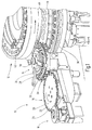
- FIGS. 3 to 7 different views of the core distributor 14 are shown.
- a series of gripping elements 28, in this case 18 pieces, are arranged in a star shape over the circumference of the rotor 26. These are all controllable by a central compressed air port 30 by four associated compressed air valves.
- a simple pneumatic control of the gripping elements 28 can be realized.
Description
- Es ist bekannt, mit Rundläufer-Tablettenpressen Mehrschicht-Tabletten herzustellen. Diese bestehen üblicherweise aus zwei oder mehr Schichten, die aufeinander folgend gepresst werden. Beispielsweise ist über den Umfang des Rotors der Rundläufer-Tablettenpresse eine entsprechende Anzahl Fülleinrichtungen mit anschließenden Druckstationen angeordnet.
- Es ist weiterhin bekannt Ein- oder Mehrschichttabletten mit einem Kern, so genannte Einleger, zu versehen. Diese Kerne werden einzeln den Matrizen zugeführt und in ein zu pressendes Medium, insbesondere Pulver, eingepresst oder von diesem ummantelt. Entscheidend bei derartigen Rundläufer-Tablettenpressen ist, dass die Kerne einzeln und definiert jeweils einer Matrize zugeführt werden, damit diese dort in eine gewünschte Position, die vorteilhaft zentriert in der Matrize ist, eingebracht werden können.
- Aus
DE 38 19 821 C2 ist bekannt, derartige Kerne mittels eines Übergabestern mit rotierenden Zuführarmen zu positionieren, wobei die Kerne an einem Haltebereich der Zuführarme durch Unterdruck gehalten werden, so dass ein Ablegen durch Abstellen des Unterdrucks möglich wird. - Ferner ist aus
DE 103 21 754 B4 bekannt, die Kerne auf einem Endlosförderer zu positionieren und den Endlosförderer über einen Teilkreis des Rotors der Tablettenpresse mitzuführen und durch die Oberstempel der Tablettenpresse in die Matrizen einzustoßen. Das Mitführen der Kerne über einen Teilkreis des Rotors führt zu aufwändigen Maßnahmen für die Positionierung der Kerne und der Synchronisierung der Bewegung der Kerne und der Matrizen. - Aus das eine Vorrichtung mit den Merkmalen des Oberbegriffs des Anspruchs 1 offenbart,
JP 59 144599 A GB 845 033 A -
DE 10 23 191 B undUS 2 879 724 A zeigen Vorrichtungen zum Einlegen von Einlegern in Matrizen von Rundläufer-Tablettenpressen bei denen Kernverteiler über Getriebe mit dem Rotor der Rundläufer-Tablettenpresse gekoppelt sind. - Der Erfindung liegt die Aufgabe zugrunde, eine Vorrichtung der gattungsgemäßen Art anzugeben, mittels derer in einfacher Weise eine sichere und zielgenaue Zuführung von Einlegern in Matrizen von Rundläufer-Tablettenpressen möglich ist.
- Erfindungsgemäß wird die Aufgabe durch eine Vorrichtung mit den im Anspruch 1 genannten Merkmalen gelöst. Dadurch, dass der wenigstens eine Kernaufnehmer durch Druckluft pneumatisch ansteuerbare Greifelemente zum Aufnehmen der Einleger, zum Zentrieren der Einleger, zum Transportieren der Einleger und zum Ausstoßen der Einleger umfasst und Ventile über eine ortsfeste Steuerkurve des Kernverteilers ansteuerbar sind, ist vorteilhaft möglich, die Einleger einzeln gezielt den Matrizen zuzuführen. Eine Übergabe beziehungsweise Einlegen der Einleger (Kerne) in die Matrizen erfolgt in einem definierten Punkt innerhalb des Bereiches, in dem sich die Bewegungsbahnen der Kernaufnehmer und der Matrizen überschneiden. Die Vorrichtung zum Einlegen der Einleger kann somit als Zusatzmodul für Rundläufer-Tablettenpressen bereitgestellt werden und ist einmalig einzujustieren. Hierzu ist die Vorrichtung so weit radial auf den Rotor der Rundläufer-Tablettenpresse zu zu bewegen, dass sich die Überschneidung der Bewegungsbahn des wenigstens einen Kernaufnehmers und der Matrizen in einem definierten Punkt auf der Radialen ergibt, auf der die Vorrichtung in Bezug auf den Rotor der Rundläufer-Tablettenpresse ausgerichtet ist.
- Dadurch, dass der Kernaufnehmer Greifelemente zum Aufnehmen der Einleger, zum Zentrieren der Einleger, zum Transportieren der Einleger und zum Ausstoßen der Einleger umfasst, wird eine sehr zielsichere und zuverlässige Zuführung der Einleger zu den Matrizen möglich. Durch die Multifunktionalität der Greifelemente ist der Aufbau der Zuführeinrichtung, insbesondere des Kernverteilers einfach und robust.
- Dadurch, dass die Greifelemente mittels Druckluft pneumatisch ansteuerbar sind, wobei vorzugsweise der Kernverteiler einen pneumatischen Anschluss umfasst, der mit Ventilen in Wirkverbindung steht, die der Ansteuerung der Greifelemente dienen, wird eine sehr zuverlässige und robuste Ansteuerung der Greifelemente möglich.
- Es wird einerseits erreicht, dass die Ansteuerung der Ventile sicher und zuverlässig immer zum richtigen Zeitpunkt erfolgt und über die Auswahl der Steuerkurve auf die zuzuführenden Einleger (Kern) abgestimmt werden kann.
- Ferner ist in bevorzugter Ausgestaltung der Erfindung vorgesehen, dass jedem Greifelement vier Ventile zugeordnet sind, nämlich zum Öffnen beziehungsweise Schließen von Greifzangen und zum Aufnehmen und Ausstoßen der Einleger. Durch Zuordnung jeder der vier Ventile einer einzelnen Funktion wird die Zuverlässigkeit der Zuführeinrichtung insbesondere des Kernverteilers sichergestellt.
- Darüber hinaus ist in bevorzugter Ausgestaltung vorgesehen, dass der Rotor des Kernverteilers durch einen steuerbaren Antrieb, vorzugsweise durch einen Schrittmotor antreibbar ist. Hierdurch wird möglich, in einfacher Weise die Drehzahl des Kernverteilers und die Drehzahl des Rotors der Rundläufer-Tablettenpresse zu synchronisieren. Somit wird eine sehr genaue Positionierung der Einleger (Kerne) in den Matrizen möglich.
- Ferner ist in bevorzugter Ausgestaltung der Erfindung vorgesehen, dass die Zuführeinrichtung eine Kernzuführeinrichtung umfasst, die mit einem Kernvereinzeler und dem Kernverteiler eine Zuführkette für die Einleger (Kerne) bildet. Hierdurch wird eine kontinuierliche Zuführung von Einlegern aus einem Vorrat mit einer unbestimmten Anzahl von Einlegern zu den Matrizen möglich.
- Es ist bevorzugt vorgesehen, dass die Kernzufuhreinrichtung einen rotierbaren Förderer umfasst, der die Kerne einzeln dem Kernverteiler definiert zuführt, wobei vorzugsweise der Förderer Positioniertaschen zur Selbstpositionierung der vereinzelten Einleger (Kerne) aufweist. Hierdurch wird vorteilhaft möglich, die Einleger zunächst zu vereinzeln und in eine definierte Position zu bringen, so dass diese von dem Kernverteiler, insbesondere von den Greifzangen der Greifelemente des Kernverteilers exakt positioniert aufgenommen werden können, so dass sichergestellt ist, dass exakt ein Einleger aufgenommen wird und dieser eine Einleger der definierten Übergabeposition zu der Matrize zugeführt wird.
- Weitere bevorzugte Ausgestaltung der Erfindung ergeben sich aus den übrigen, in den Unteransprüchen genannten Merkmalen.
- Die vorliegende Erfindung schlägt also vor, die Übergabe der Kerne, beziehungsweise allgemein der vorzugsweise festen Einleger, in die Matrizen mittels eines so genannten Kernverteilers vorzunehmen. Dieser Kernverteiler besitzt einen Rotor, der über seinen Umfang eine gewünschte Anzahl, beispielsweise 18, Kernaufnehmer umfasst. Der Kernverteiler und der Matrizentisch der Tablettenpresse überschneiden sich in einem Teilkreis, so dass die Kernaufnehmer in eine exakt definierbare Position oberhalb der Matrizen des Matrizentisches gebracht werden können.
- Die Kernaufnehmer besitzen Greifelemente, mittels denen die Kerne an einer Aufnahmeposition aufgenommen werden können, die Kerne transportiert werden können und an der Abgabeposition oberhalb der Matrizen abgegeben werden können. Die Greifer sind vorzugsweise pneumatisch antreibbar, so dass durch Ansteuerung entsprechender Ventile die Funktionen der Greifer, nämlich Aufnehmen der Kerne, Zentrieren der Kerne, Transportieren der Kerne und Ausstoßen der Kerne, möglich sind.
- Der Rotor des Kernverteilers ist vorzugsweise elektrisch, beispielsweise mittels eines Servomotors, angetrieben. So ist in einfacher Weise eine Drehzahl des Rotors des Kernverteilers synchronisierbar mit der Umdrehungsgeschwindigkeit des Rotors beziehungsweise Matrizentisches der Tablettenpresse. Auch andere Antriebe sind denkbar. Zum Beispiel über vorgesehene Inkrementalgeber kann hier ein aufeinander abgestimmtes Ansteuern erfolgen, so dass die exakte Positionierung der Kerne zu den Matrizen möglich ist und diese somit sehr zentriert in die Matrizen eingebracht werden können.
- Die Erfindung wird nachfolgend anhand der zugehörigen Zeichnung näher erläutert. Es zeigen:
- Figur 1
- eine schematische Perspektivansicht einer Zuführanrichtung von Kernen/Einlegern zu einer Tablettenpresse;
- Figur 2
- eine schematische Perspektivansicht eines Aufnahmebereichs des Kernverteilers und
- Figuren 3 bis 7
- verschiedene Ansichten des Kernverteilers.
-
Figur 1 zeigt eine schematische Perspektivansicht einer insgesamt mit 10 bezeichneten Zuführeinrichtung für Kerne zu einer insgesamt mit 12 bezeichneten Rundläufer-Tablettenpresse. Aufbau und Funktion von Rundläufer-Tablettenpressen sind allgemein bekannt, so dass im Rahmen der vorliegenden Beschreibung hierauf im Detail nicht eingegangen werden soll. - Kern und Gegenstand der Erfindung ist insbesondere die Zuführeinrichtung 10, die mit einer Rundläufer-Tablettenpresse 12 kombiniert werden kann.
- Die Zuführeinrichtung 10 umfasst einen Kernverteiler 14, eine Kernzuführung 16 und einen Kernvereinzeler 18.
- Der Kernvereinzeler 18 führt einzeln, beispielsweise über einen Endlosförderer, die Kerne aus einem Vorratsbehälter der Zuführeinrichtung 10 zu. Die Kerne werden dann einzeln der Kernzuführeinrichtung 16 übergeben. Die Kernzuführeinrichtung 16 umfasst einen rotierbaren Förderer 20, der Öffnungen 22 auf einer Umfangslinie aufweist. Unterhalb des Förderers 20 ist eine feststehende Führungsfläche 24, beispielsweise eine Scheibe oder ein im Bereich der Öffnung 22 angeordneter Ring, angeordnet. Hierdurch entstehen durch die Öffnungen 22 Fördertaschen, in die die Kerne durch den Kernvereinzeler 18 eingelegt werden. In jeder der Öffnungen 22 (Taschen) kommt genau ein Kern zum Liegen. Durch die Formgestaltung der Öffnungen 22 - in Draufsicht gesehen - werden während der Transportbewegung der Kerne diese in eine exakt definierte Position gebracht. Die Kerne werden quasi über die Führungsfläche 24 geschoben und kommen am - in Drehrichtung betrachtet hinten liegenden - Ende der Öffnungen 22 zu einem Positionieranschlag. Die Drehrichtung ist durch ein Pfeil angedeutet.
- Der Kernverteiler 14 umfasst einen Rotor 26, der über seinen Umfang Greifelemente 28 aufweist. Die Greifelemente 28 besitzen zangenartige Greifer, die pneumatisch ansteuerbar sind. Über einen hier angedeuteten Pneumatikanschluss 30 erfolgt eine Druckluftzufuhr zu dem Kernverteiler 14. Über, im Kernverteiler 14 angeordnete, Ventile 32, die über Steuerkurven 34 ansteuerbar sind werden die Greifelemente 28 betätigt. Somit kann während der Rotation des Rotors 26 ein definiertes Ansteuern der Ventile 32 der Greifelemente 28 erfolgen. Für jedes Greifelement 28 sind vier Steuerventile 32 vorgesehen, die einerseits ein Öffnen, ein Schließen der Greifer (Greifzangen 44,
Figur 4 ), beziehungsweise ein Aufnehmen und ein Ausstoßen der Kerne ermöglichen. - Der Rotor 26 des Kernverteilers 14 ist durch einen im Detail nicht dargestellten steuerbaren Antrieb antreibbar. Hierdurch wird es möglich, die Drehzahl beziehungsweise die Schrittgeschwindigkeit, mit welcher der Rotor 26 seine Position verändert, an die Umdrehung des Rotors 36 der Rundläufer-Tablettenpresse 12 zu synchronisieren. Die Rundläufer-Tablettenpresse 12 umfasst bekanntermaßen einen Matrizentisch 38, der, auf einer Umfangslinie angeordnete, Matrizen 40 aufweist. Jeder Matrize 40 ist ein Unterstempel und ein Oberstempel zugeordnet, von den hier schematisch drei Oberstempel 42 angedeutet sind. Über Kurven wird die Hubbewegung der Unter- und Oberstempel bekannterweise realisiert, so dass es zum Füllen der Matrizen 40, zum Pressen der in die Matrizen 40 eingefüllten Medien und zum Auswerfen der fertigen Tabletten kommt.
- Die Darstellung in
Figur 1 verdeutlicht, dass der Kernverteiler 14 in den Rotor 36 eingreift, wobei dieser oberhalb des Matrizentisches 38 und unterhalb der Oberstempel 42 angeordnet ist. Hierdurch können die Greifelemente 28 in Überdeckung mit den Matrizen 40 gebracht werden, ohne dass es zu einer Beeinträchtigung der Drehbewegung des Rotors 36 der Tablettenpresse 12 beziehungsweise der Drehbewegung des Rotors 26 des Kernverteilers 14 kommt. - Die in
Figur 1 dargestellte Anordnung zeigt folgende Funktion: - Die in die Matrizen einzulegenden Kerne werden über den Kernvereinzeler 18 der Kernzuführeinrichtung 16 zugeführt. Die Kerne werden hier einzeln in die Öffnungen 22 eingebracht und zu dem Kernverteiler 14 transportiert. Im Bereich des Kernverteilers 14 ist die Führungsfläche 24 unterbrochen, so dass die Kerne quasi nach unten durchfallen und hier von Greifzangen 44 der Greifelemente 28 aufgenommen werden können. Die Greifzangen 44 bilden einen Aufnahmebereich aus der an die Größe und Form der einzulegenden Kerne angepasst ist. Die Greifzangen 44 können austauschbar sein, so dass eine Umrüstung auf unterschiedliche Kerngrößen und Kernformen ohne Probleme möglich ist.
-
Figur 2 verdeutlicht den Übergabebereich zwischen der Kernzuführeinrichtung 16 und dem Kernverteiler 14. Der Rotor 26 des Kernverteilers 14 besitzt eine feststehende Führungsfläche 46 die zumindest im Bereich der Übergabe der Kerne von der Kernzuführeinrichtung 16 perforiert und mit einem Unterdruck beaufschlagbar ist. Hierdurch werden die Kerne quasi an die Führungsfläche 46 angesaugt und in Position gehalten. Die Greifzangen 44 werden dann durch Betätigen der zugeordneten pneumatischen Steuerventile 32 über die Steuerkurven 34 geschlossen, wie dies inFigur 2 anhand der geöffneten Position 44 und der geschlossenen Position 44' deutlich wird. Die Greifzangen 44 transportieren dann die Kerne in den Bereich des Rotors 36 der Tablettenpresse 12. Der Aufnahmebereich der Greifzangen 44 wird hierbei über jeweils eine gerade vorbeirotierende Matrize 40 geführt. Befindet sich der Aufnahmebereich der Greifzangen 44 über einer Matrize 40, wird über die pneumatische Steuerung des Kernverteilers 14 ein oberhalb des Aufnahmebereiches der Greifzangen 44 befindlicher Stößel 48 angesteuert. Dieser stößt den Kern nach unten aus den Greifzangen 44 heraus in die entsprechende Matrize 40. Der Stößel 48 wird ebenfalls über die Kurvenscheibe 34 angesteuert. - Es wird deutlich, dass durch die Anordnung des Kernverteilers 14 eine kontinuierliche Zuführung von Kernen zu den Matrizen 40 möglich ist. Durch die synchronisierte Ansteuerung sowohl des Kernverteilers 14 als auch der Kernzuführeinrichtung 16 wird mit der Antriebssteuerung des Rotors 36 der Rundläufer-Tablettenpresse ein zielgenaues und exaktes Zuführen jeweils eines Kernes in eine Matrize 40 möglich, wobei hier insbesondere eine mittige, das heißt definierte, Platzierung der Kerne erfolgt.
- In den
Figuren 3 bis 7 sind verschiedene Ansichten des Kernverteilers 14 gezeigt. Es wird insbesondere deutlich, dass über den Umfang des Rotors 26 sternförmig eine Reihe von Greifelemente 28, hier 18 Stück, angeordnet sind. Diese sind alle durch einen zentralen Druckluftanschluss 30 durch jeweils vier zugeordnete Druckluftventile steuerbar. Über feststehende Kurvenscheiben lässt sich so eine einfache pneumatische Steuerung der Greifelemente 28 realisieren. Insbesondere ist eine definierte Aufnahme der Kerne, ein sicherer Transport und eine definierte, den einzelnen Matrizen 40 zugeordnete, Abgabe der Kerne in sicherer Weise möglich. -
- 10
- Zuführeinrichtung
- 12
- Rundläufer-Tablettenpresse
- 14
- Kernverteiler
- 16
- Kernzuführeinrichtung
- 18
- Kernvereinzeler
- 20
- rotierbarer Förderer
- 22
- Öffnung
- 24
- feststehende Führungsfläche
- 26
- Rotor des Kernverteilers 14
- 28
- Greifelemente
- 30
- zentraler Druckluftanschluss
- 32
- Steuerventile
- 34
- Steuerkurven
- 36
- Rotor
- 38
- Matrizentisch
- 40
- Matrize
- 42
- Oberstempel
- 44
- Greifzangen
- 44'
- geschlossene Position
- 46
- Führungsfläche
- 48
- Stößel
Claims (7)
- Vorrichtung zum Einlegen von Einlegern in Matrizen (40) einer Rundläufer-Tablettenpresse (12) mit einer Zuführeinrichtung, über die vereinzelte Einleger in Überdeckung mit einer Matrize der Rundläufer-Tablettenpresse gebracht werden, die Zuführeinrichtung (10) einen Kernverteiler (14) umfasst, der Kernverteiler (14) einen antreibbaren Rotor (26) besitzt, der über seinen Umfang wenigstens einen Kernaufnehmer umfasst, und eine Bewegungsbahn des wenigstens einen Kernaufnehmers und eine Bewegungsbahn der Matrizen (40) der Rundläufer-Tablettenpresse sich in einem Teilkreis überschneiden,
dadurch gekennzeichnet, dass
der wenigstens eine Kernaufnehmer durch Druckluft pneumatisch ansteuerbare Greifelemente (28) zum Aufnehmen der Einleger, zum Zentrieren der Einleger, zum Transportieren der Einleger und zum Ausstoßen der Einleger umfasst und der Kernverteiler (14) einen Pneumatikanschluss (30) umfasst, der mit den Ventilen (32) in Wirkverbindung steht, die der Ansteuerung der Greifelemente (28) dienen und wobei die Ventile (32) zur Ansteuerung der Greifelemente über eine ortsfeste Steuerkurve (34) des Kernverteilers (14) ansteuerbar sind. - Vorrichtung nach einem der vorhergehenden Ansprüche,
dadurch gekennzeichnet, dass
jedem Greifelement (28) vier Ventile (32) zugeordnet sind, zum Öffnen beziehungsweise Schließen von Greifzangen (44) und zum Aufnehmen und Ausstoßen der Einleger. - Vorrichtung nach einem der vorhergehenden Ansprüche,
dadurch gekennzeichnet, dass
der Rotor (26) des Kernverteilers (14) durch einen steuerbaren Antrieb antreibbar ist. - Vorrichtung nach Anspruch 3,
dadurch gekennzeichnet, dass
der Rotor (26) durch einen Schrittmotor antreibbar ist. - Vorrichtung nach einem der vorhergehenden Ansprüche,
dadurch gekennzeichnet, dass
die Zuführeinrichtung (10) eine Kernzuführeinrichtung (16) umfasst, der mit einem Kernvereinzeler (18) und dem Kernverteiler (14) eine Zuführkette für die Einleger bildet. - Vorrichtung nach einem der vorhergehenden Ansprüche,
dadurch gekennzeichnet, dass
die Kernzuführeinrichtung (16) einen rotierbaren Förderer (20) umfasst, der die Einleger einzeln den Kernverteiler (14) definiert zuführt. - Vorrichtung nach Anspruch 6,
dadurch gekennzeichnet, dass
der Förderer (20) Positioniertaschen (22) zur Selbstpositionierung der vereinzelten Einleger aufweist.
Applications Claiming Priority (1)
| Application Number | Priority Date | Filing Date | Title |
|---|---|---|---|
| DE102008020758 | 2008-04-18 |
Publications (3)
| Publication Number | Publication Date |
|---|---|
| EP2110232A2 EP2110232A2 (de) | 2009-10-21 |
| EP2110232A3 EP2110232A3 (de) | 2011-04-27 |
| EP2110232B1 true EP2110232B1 (de) | 2016-09-14 |
Family
ID=40679435
Family Applications (1)
| Application Number | Title | Priority Date | Filing Date |
|---|---|---|---|
| EP09158068.8A Not-in-force EP2110232B1 (de) | 2008-04-18 | 2009-04-16 | Vorrichtung zum Einlegen von Einlegern in Matrizen einer Rundläufer-Tablettenpresse |
Country Status (4)
| Country | Link |
|---|---|
| US (1) | US9114585B2 (de) |
| EP (1) | EP2110232B1 (de) |
| DE (1) | DE102009002450A1 (de) |
| ES (1) | ES2605615T3 (de) |
Families Citing this family (33)
| Publication number | Priority date | Publication date | Assignee | Title |
|---|---|---|---|---|
| US8912908B2 (en) | 2005-04-28 | 2014-12-16 | Proteus Digital Health, Inc. | Communication system with remote activation |
| US8802183B2 (en) | 2005-04-28 | 2014-08-12 | Proteus Digital Health, Inc. | Communication system with enhanced partial power source and method of manufacturing same |
| US8836513B2 (en) | 2006-04-28 | 2014-09-16 | Proteus Digital Health, Inc. | Communication system incorporated in an ingestible product |
| EP2392258B1 (de) | 2005-04-28 | 2014-10-08 | Proteus Digital Health, Inc. | Pharma-Informatiksystem |
| US9270025B2 (en) | 2007-03-09 | 2016-02-23 | Proteus Digital Health, Inc. | In-body device having deployable antenna |
| KR101214453B1 (ko) | 2008-08-13 | 2012-12-24 | 프로테우스 디지털 헬스, 인코포레이티드 | 복용 가능한 회로 |
| CN102458236B (zh) | 2009-04-28 | 2016-01-27 | 普罗秋斯数字健康公司 | 高可靠性的可摄入事件标记器及其使用方法 |
| WO2010132331A2 (en) | 2009-05-12 | 2010-11-18 | Proteus Biomedical, Inc. | Ingestible event markers comprising an ingestible component |
| WO2011127252A2 (en) | 2010-04-07 | 2011-10-13 | Proteus Biomedical, Inc. | Miniature ingestible device |
| JP2014504902A (ja) | 2010-11-22 | 2014-02-27 | プロテウス デジタル ヘルス, インコーポレイテッド | 医薬品を有する摂取可能なデバイス |
| CN102225626A (zh) * | 2011-03-25 | 2011-10-26 | 湘潭华诚机械有限公司 | 多工位立式回转工作台全自动等静压成型机 |
| WO2015112603A1 (en) | 2014-01-21 | 2015-07-30 | Proteus Digital Health, Inc. | Masticable ingestible product and communication system therefor |
| US9756874B2 (en) | 2011-07-11 | 2017-09-12 | Proteus Digital Health, Inc. | Masticable ingestible product and communication system therefor |
| WO2014018454A1 (en) * | 2012-07-23 | 2014-01-30 | Proteus Digital Health, Inc. | Techniques for manufacturing ingestible event markers comprising an ingestible component |
| JP5869736B2 (ja) | 2012-10-18 | 2016-02-24 | プロテウス デジタル ヘルス, インコーポレイテッド | 通信デバイス用の電源において電力消失およびブロードキャスト電力を適応的に最適化するための装置、システム、および方法 |
| TWI659994B (zh) | 2013-01-29 | 2019-05-21 | 美商普羅托斯數位健康公司 | 高度可膨脹之聚合型薄膜及包含彼之組成物 |
| DE102013001451A1 (de) * | 2013-01-29 | 2014-07-31 | Korsch Ag | Übergabe- und Positioniervorrichtung für eine Tablette oder einen Tablettenrohling |
| JP5941240B2 (ja) | 2013-03-15 | 2016-06-29 | プロテウス デジタル ヘルス, インコーポレイテッド | 金属検出器装置、システム、および方法 |
| DE102013104344B4 (de) | 2013-04-29 | 2015-07-09 | Kilian Tableting Gmbh | Vorrichtung zum Einlegen von Einlegern in Matrizen einer Tablettenpresse |
| CN104411283B (zh) * | 2013-05-16 | 2019-01-04 | 科施股份公司 | 用于将薄膜放置在压片机中的装置和方法 |
| ES2637382T3 (es) * | 2013-07-11 | 2017-10-13 | Korsch Ag | Dispositivo y procedimiento para insertar películas en prensas para comprimidos |
| US9796576B2 (en) | 2013-08-30 | 2017-10-24 | Proteus Digital Health, Inc. | Container with electronically controlled interlock |
| US10084880B2 (en) | 2013-11-04 | 2018-09-25 | Proteus Digital Health, Inc. | Social media networking based on physiologic information |
| DE102014107026B4 (de) | 2014-05-19 | 2017-07-13 | Romaco Kilian Gmbh | Vorrichtung zum Herstellen von Kerntabletten sowie Mantelkerntabletten (Doppelkern- oder Mehrfachkerntablette) |
| US11051543B2 (en) | 2015-07-21 | 2021-07-06 | Otsuka Pharmaceutical Co. Ltd. | Alginate on adhesive bilayer laminate film |
| US20170151743A1 (en) * | 2015-12-01 | 2017-06-01 | Kikusui Seisakusho Ltd. | Molded product discharge device |
| KR20210018961A (ko) | 2016-07-22 | 2021-02-18 | 프로테우스 디지털 헬스, 인코포레이티드 | 섭취 가능한 이벤트 마커의 전자기 감지 및 검출 |
| IL265827B2 (en) | 2016-10-26 | 2023-03-01 | Proteus Digital Health Inc | Methods for producing capsules with ingestible event markers |
| JP6968417B2 (ja) * | 2018-02-05 | 2021-11-17 | 株式会社菊水製作所 | 粉体圧縮成形機とモジュールとの連結構造 |
| EP3599087A1 (de) * | 2018-07-25 | 2020-01-29 | Korsch AG | Vorrichtung zur bereitstellung von einlegern an eine tablettiermaschine, sowie ein verfahren zur herstellung eines presslings, der einen einleger aufweist |
| CN108973152A (zh) * | 2018-09-01 | 2018-12-11 | 韦美芬 | 一种用于装配led灯的塑胶件送料机构 |
| CN110948202A (zh) * | 2019-12-02 | 2020-04-03 | 张美华 | 一种用于电连接件焊接的焊接插片组装装置及其方法 |
| WO2023222688A1 (de) | 2022-05-18 | 2023-11-23 | Korsch Ag | Vorrichtung zum einlegen von mindestens einem objekt in mindestens eine matrize einer tablettiermaschine |
Citations (2)
| Publication number | Priority date | Publication date | Assignee | Title |
|---|---|---|---|---|
| US3872203A (en) * | 1972-06-07 | 1975-03-18 | Kureha Chemical Ind Co Ltd | Method for producing biaxially stretched receptacles by blow molding |
| EP1155811A2 (de) * | 2000-05-17 | 2001-11-21 | Wilhelm Fette GmbH | Rundläufer-Tablettenpresse für die Herstellung von mehrschichtigen Tabletten |
Family Cites Families (16)
| Publication number | Priority date | Publication date | Assignee | Title |
|---|---|---|---|---|
| DE1023191B (de) * | 1954-04-15 | 1958-01-23 | John Holroyd & Co Ltd | Verfahren und Vorrichtung zum Herstellen ueberzogener Tabletten |
| US2879724A (en) * | 1954-07-20 | 1959-03-31 | Stokes F J Corp | Tablet coating machine |
| US2946298A (en) * | 1957-11-13 | 1960-07-26 | Arthur Colton Company | Compression coating tablet press |
| GB845033A (en) * | 1957-12-14 | 1960-08-17 | John Holroyd And Company Ltd | Improvements in or relating to machines for making coated tablets |
| US2963993A (en) * | 1959-01-20 | 1960-12-13 | John Holroyd & Company Ltd | Machines for making coated tablets by compression |
| US4011039A (en) * | 1975-04-07 | 1977-03-08 | Beloit Corporation | Parison transfer device |
| JPS59120399A (ja) | 1982-12-27 | 1984-07-11 | Kikusui Seisakusho:Kk | 回転式有核錠剤機における核のセンタリング装置 |
| JPS59144598A (ja) * | 1983-02-03 | 1984-08-18 | Hata Tekkosho:Kk | 回転式粉末成形機の物品供給装置 |
| JPS59144599A (ja) * | 1983-02-03 | 1984-08-18 | Hata Tekkosho:Kk | 回転式粉末成形機の物品供給装置 |
| US5088915A (en) * | 1988-06-08 | 1992-02-18 | Korsch Ohg Maschinenfabrik | Coated-core press |
| DE4025484C1 (de) * | 1990-08-08 | 1991-10-10 | Korsch Maschfab | |
| US5376313A (en) * | 1992-03-27 | 1994-12-27 | Abbott Laboratories | Injection molding a plastic assay cuvette having low birefringence |
| US6176699B1 (en) * | 1999-04-28 | 2001-01-23 | Walbro Corporation | Parison handling device |
| US6767200B2 (en) * | 2001-09-28 | 2004-07-27 | Mcneil-Ppc, Inc. | Systems, methods and apparatuses for manufacturing dosage forms |
| DE10321754B4 (de) | 2003-05-15 | 2006-03-02 | Fette Gmbh | Verfahren und Vorrichtung zum Einlegen von festen Bestandteilen (Einleger) in Matrizen einer Rundläufer-Tablettierpresse |
| DE102007039043A1 (de) | 2007-08-17 | 2009-02-19 | Grünenthal GmbH | Sternverteiler |
-
2009
- 2009-04-16 ES ES09158068.8T patent/ES2605615T3/es active Active
- 2009-04-16 DE DE200910002450 patent/DE102009002450A1/de not_active Withdrawn
- 2009-04-16 US US12/424,540 patent/US9114585B2/en not_active Expired - Fee Related
- 2009-04-16 EP EP09158068.8A patent/EP2110232B1/de not_active Not-in-force
Patent Citations (2)
| Publication number | Priority date | Publication date | Assignee | Title |
|---|---|---|---|---|
| US3872203A (en) * | 1972-06-07 | 1975-03-18 | Kureha Chemical Ind Co Ltd | Method for producing biaxially stretched receptacles by blow molding |
| EP1155811A2 (de) * | 2000-05-17 | 2001-11-21 | Wilhelm Fette GmbH | Rundläufer-Tablettenpresse für die Herstellung von mehrschichtigen Tabletten |
Also Published As
| Publication number | Publication date |
|---|---|
| US9114585B2 (en) | 2015-08-25 |
| EP2110232A3 (de) | 2011-04-27 |
| DE102009002450A1 (de) | 2009-10-22 |
| US20090260212A1 (en) | 2009-10-22 |
| ES2605615T3 (es) | 2017-03-15 |
| EP2110232A2 (de) | 2009-10-21 |
Similar Documents
| Publication | Publication Date | Title |
|---|---|---|
| EP2110232B1 (de) | Vorrichtung zum Einlegen von Einlegern in Matrizen einer Rundläufer-Tablettenpresse | |
| EP2825465B1 (de) | Vorrichtung und verfahren zur herstellung von filtern und einsetzen der filter in portionskapseln zur getränkezubereitung | |
| DE4106014C2 (de) | Verfahren und Vorrichtung zum Formen, Umformen und Bördeln von Deckeln in einer einzelnen Presse | |
| DE3617259C2 (de) | ||
| EP0008379B1 (de) | Einrichtung für das Aufnehmen/Ablegen und Transportieren von kleinen Werkstücken | |
| DE1627733A1 (de) | Werkstuecktransportmechanismus fuer Montagemaschinen od.dgl. | |
| EP0444547A1 (de) | Verfahren und Vorrichtung zum Fördern von Banderolen zwecks Übergabe an Packungen | |
| EP0320731B1 (de) | Prägeautomat für Ring-Kern-Münzen | |
| EP3374104B1 (de) | Zuführvorrichtung für rondenringe | |
| DE3416078A1 (de) | Anlage, verfahren und vorrichtung zur herstellung von behaeltern | |
| EP2049063A1 (de) | Vorrichtung und verfahren zum ausstossen zumindest einer kapsel | |
| WO2017162848A1 (de) | Rundlaufpresse mit stempeln mit mindestens zwei höhengestaffelten stempelspitzen zum ausführen von mehreren pressvorgängen während eines rundlaufes | |
| EP3429799B1 (de) | Einsetzvorrichtung und verfahren zum einsetzen eines rondenrings in einen aussenring einer ronde | |
| DE2823838A1 (de) | Signatur oder heftmaschinen | |
| DE10026731C2 (de) | Rundläufer-Tablettenpresse für die Herstellung von mehrschichtigen Tabletten | |
| DE10321754B4 (de) | Verfahren und Vorrichtung zum Einlegen von festen Bestandteilen (Einleger) in Matrizen einer Rundläufer-Tablettierpresse | |
| EP3349992B1 (de) | Transportvorrichtung zum transportieren von münzrohlingen und verfahren zur herstellung einer münze | |
| EP1593633B1 (de) | Vorrichtung zum Bilden von Stapeln aus Druckprodukten | |
| DE10057000A1 (de) | Vorrichtung zum Herstellen von "Zwei- oder Multimetallmünzen" aus unterschiedlichen Metallen | |
| DE2250682C3 (de) | Vorrichtung zum Einbringen von Gegenständen in einen Verpackungskarton | |
| DE2009138A1 (en) | Sheet stamping transfer device | |
| DE102022126031A1 (de) | Mechatronische und modulare kapselmaschine für nahrungsmittel- oder getränkebehälter | |
| DE1940567A1 (de) | Vorrichtung zur vollautomatischen Montage elektrischer Bauteile | |
| EP1473234B1 (de) | Verpackungseinrichtung für Stapel von Flachteilen | |
| DE1704801C3 (de) | Automatische Schallplattenpresse |
Legal Events
| Date | Code | Title | Description |
|---|---|---|---|
| PUAI | Public reference made under article 153(3) epc to a published international application that has entered the european phase |
Free format text: ORIGINAL CODE: 0009012 |
|
| AK | Designated contracting states |
Kind code of ref document: A2 Designated state(s): AT BE BG CH CY CZ DE DK EE ES FI FR GB GR HR HU IE IS IT LI LT LU LV MC MK MT NL NO PL PT RO SE SI SK TR |
|
| PUAL | Search report despatched |
Free format text: ORIGINAL CODE: 0009013 |
|
| AK | Designated contracting states |
Kind code of ref document: A3 Designated state(s): AT BE BG CH CY CZ DE DK EE ES FI FR GB GR HR HU IE IS IT LI LT LU LV MC MK MT NL NO PL PT RO SE SI SK TR |
|
| 17P | Request for examination filed |
Effective date: 20110926 |
|
| 17Q | First examination report despatched |
Effective date: 20131204 |
|
| GRAP | Despatch of communication of intention to grant a patent |
Free format text: ORIGINAL CODE: EPIDOSNIGR1 |
|
| INTG | Intention to grant announced |
Effective date: 20160304 |
|
| GRAJ | Information related to disapproval of communication of intention to grant by the applicant or resumption of examination proceedings by the epo deleted |
Free format text: ORIGINAL CODE: EPIDOSDIGR1 |
|
| GRAJ | Information related to disapproval of communication of intention to grant by the applicant or resumption of examination proceedings by the epo deleted |
Free format text: ORIGINAL CODE: EPIDOSDIGR1 |
|
| GRAS | Grant fee paid |
Free format text: ORIGINAL CODE: EPIDOSNIGR3 |
|
| GRAP | Despatch of communication of intention to grant a patent |
Free format text: ORIGINAL CODE: EPIDOSNIGR1 |
|
| INTC | Intention to grant announced (deleted) | ||
| GRAA | (expected) grant |
Free format text: ORIGINAL CODE: 0009210 |
|
| INTG | Intention to grant announced |
Effective date: 20160729 |
|
| AK | Designated contracting states |
Kind code of ref document: B1 Designated state(s): AT BE BG CH CY CZ DE DK EE ES FI FR GB GR HR HU IE IS IT LI LT LU LV MC MK MT NL NO PL PT RO SE SI SK TR |
|
| REG | Reference to a national code |
Ref country code: GB Ref legal event code: FG4D Free format text: NOT ENGLISH |
|
| REG | Reference to a national code |
Ref country code: CH Ref legal event code: EP |
|
| REG | Reference to a national code |
Ref country code: IE Ref legal event code: FG4D Free format text: LANGUAGE OF EP DOCUMENT: GERMAN |
|
| REG | Reference to a national code |
Ref country code: AT Ref legal event code: REF Ref document number: 828473 Country of ref document: AT Kind code of ref document: T Effective date: 20161015 |
|
| REG | Reference to a national code |
Ref country code: DE Ref legal event code: R096 Ref document number: 502009013087 Country of ref document: DE |
|
| REG | Reference to a national code |
Ref country code: LT Ref legal event code: MG4D |
|
| REG | Reference to a national code |
Ref country code: NL Ref legal event code: MP Effective date: 20160914 |
|
| PG25 | Lapsed in a contracting state [announced via postgrant information from national office to epo] |
Ref country code: LT Free format text: LAPSE BECAUSE OF FAILURE TO SUBMIT A TRANSLATION OF THE DESCRIPTION OR TO PAY THE FEE WITHIN THE PRESCRIBED TIME-LIMIT Effective date: 20160914 Ref country code: HR Free format text: LAPSE BECAUSE OF FAILURE TO SUBMIT A TRANSLATION OF THE DESCRIPTION OR TO PAY THE FEE WITHIN THE PRESCRIBED TIME-LIMIT Effective date: 20160914 Ref country code: FI Free format text: LAPSE BECAUSE OF FAILURE TO SUBMIT A TRANSLATION OF THE DESCRIPTION OR TO PAY THE FEE WITHIN THE PRESCRIBED TIME-LIMIT Effective date: 20160914 Ref country code: NO Free format text: LAPSE BECAUSE OF FAILURE TO SUBMIT A TRANSLATION OF THE DESCRIPTION OR TO PAY THE FEE WITHIN THE PRESCRIBED TIME-LIMIT Effective date: 20161214 |
|
| PG25 | Lapsed in a contracting state [announced via postgrant information from national office to epo] |
Ref country code: NL Free format text: LAPSE BECAUSE OF FAILURE TO SUBMIT A TRANSLATION OF THE DESCRIPTION OR TO PAY THE FEE WITHIN THE PRESCRIBED TIME-LIMIT Effective date: 20160914 Ref country code: GR Free format text: LAPSE BECAUSE OF FAILURE TO SUBMIT A TRANSLATION OF THE DESCRIPTION OR TO PAY THE FEE WITHIN THE PRESCRIBED TIME-LIMIT Effective date: 20161215 Ref country code: SE Free format text: LAPSE BECAUSE OF FAILURE TO SUBMIT A TRANSLATION OF THE DESCRIPTION OR TO PAY THE FEE WITHIN THE PRESCRIBED TIME-LIMIT Effective date: 20160914 Ref country code: LV Free format text: LAPSE BECAUSE OF FAILURE TO SUBMIT A TRANSLATION OF THE DESCRIPTION OR TO PAY THE FEE WITHIN THE PRESCRIBED TIME-LIMIT Effective date: 20160914 |
|
| REG | Reference to a national code |
Ref country code: ES Ref legal event code: FG2A Ref document number: 2605615 Country of ref document: ES Kind code of ref document: T3 Effective date: 20170315 |
|
| PG25 | Lapsed in a contracting state [announced via postgrant information from national office to epo] |
Ref country code: RO Free format text: LAPSE BECAUSE OF FAILURE TO SUBMIT A TRANSLATION OF THE DESCRIPTION OR TO PAY THE FEE WITHIN THE PRESCRIBED TIME-LIMIT Effective date: 20160914 Ref country code: EE Free format text: LAPSE BECAUSE OF FAILURE TO SUBMIT A TRANSLATION OF THE DESCRIPTION OR TO PAY THE FEE WITHIN THE PRESCRIBED TIME-LIMIT Effective date: 20160914 |
|
| PG25 | Lapsed in a contracting state [announced via postgrant information from national office to epo] |
Ref country code: PT Free format text: LAPSE BECAUSE OF FAILURE TO SUBMIT A TRANSLATION OF THE DESCRIPTION OR TO PAY THE FEE WITHIN THE PRESCRIBED TIME-LIMIT Effective date: 20170116 Ref country code: CZ Free format text: LAPSE BECAUSE OF FAILURE TO SUBMIT A TRANSLATION OF THE DESCRIPTION OR TO PAY THE FEE WITHIN THE PRESCRIBED TIME-LIMIT Effective date: 20160914 Ref country code: BG Free format text: LAPSE BECAUSE OF FAILURE TO SUBMIT A TRANSLATION OF THE DESCRIPTION OR TO PAY THE FEE WITHIN THE PRESCRIBED TIME-LIMIT Effective date: 20161214 Ref country code: IS Free format text: LAPSE BECAUSE OF FAILURE TO SUBMIT A TRANSLATION OF THE DESCRIPTION OR TO PAY THE FEE WITHIN THE PRESCRIBED TIME-LIMIT Effective date: 20170114 Ref country code: PL Free format text: LAPSE BECAUSE OF FAILURE TO SUBMIT A TRANSLATION OF THE DESCRIPTION OR TO PAY THE FEE WITHIN THE PRESCRIBED TIME-LIMIT Effective date: 20160914 Ref country code: SK Free format text: LAPSE BECAUSE OF FAILURE TO SUBMIT A TRANSLATION OF THE DESCRIPTION OR TO PAY THE FEE WITHIN THE PRESCRIBED TIME-LIMIT Effective date: 20160914 |
|
| REG | Reference to a national code |
Ref country code: DE Ref legal event code: R097 Ref document number: 502009013087 Country of ref document: DE |
|
| PLBE | No opposition filed within time limit |
Free format text: ORIGINAL CODE: 0009261 |
|
| STAA | Information on the status of an ep patent application or granted ep patent |
Free format text: STATUS: NO OPPOSITION FILED WITHIN TIME LIMIT |
|
| PG25 | Lapsed in a contracting state [announced via postgrant information from national office to epo] |
Ref country code: DK Free format text: LAPSE BECAUSE OF FAILURE TO SUBMIT A TRANSLATION OF THE DESCRIPTION OR TO PAY THE FEE WITHIN THE PRESCRIBED TIME-LIMIT Effective date: 20160914 |
|
| 26N | No opposition filed |
Effective date: 20170615 |
|
| REG | Reference to a national code |
Ref country code: DE Ref legal event code: R119 Ref document number: 502009013087 Country of ref document: DE |
|
| PG25 | Lapsed in a contracting state [announced via postgrant information from national office to epo] |
Ref country code: SI Free format text: LAPSE BECAUSE OF FAILURE TO SUBMIT A TRANSLATION OF THE DESCRIPTION OR TO PAY THE FEE WITHIN THE PRESCRIBED TIME-LIMIT Effective date: 20160914 |
|
| REG | Reference to a national code |
Ref country code: CH Ref legal event code: PL |
|
| GBPC | Gb: european patent ceased through non-payment of renewal fee |
Effective date: 20170416 |
|
| REG | Reference to a national code |
Ref country code: IE Ref legal event code: MM4A |
|
| REG | Reference to a national code |
Ref country code: FR Ref legal event code: ST Effective date: 20171229 |
|
| PG25 | Lapsed in a contracting state [announced via postgrant information from national office to epo] |
Ref country code: MC Free format text: LAPSE BECAUSE OF FAILURE TO SUBMIT A TRANSLATION OF THE DESCRIPTION OR TO PAY THE FEE WITHIN THE PRESCRIBED TIME-LIMIT Effective date: 20160914 Ref country code: DE Free format text: LAPSE BECAUSE OF NON-PAYMENT OF DUE FEES Effective date: 20171103 Ref country code: FR Free format text: LAPSE BECAUSE OF NON-PAYMENT OF DUE FEES Effective date: 20170502 |
|
| PG25 | Lapsed in a contracting state [announced via postgrant information from national office to epo] |
Ref country code: CH Free format text: LAPSE BECAUSE OF NON-PAYMENT OF DUE FEES Effective date: 20170430 Ref country code: LU Free format text: LAPSE BECAUSE OF NON-PAYMENT OF DUE FEES Effective date: 20170416 Ref country code: GB Free format text: LAPSE BECAUSE OF NON-PAYMENT OF DUE FEES Effective date: 20170416 Ref country code: LI Free format text: LAPSE BECAUSE OF NON-PAYMENT OF DUE FEES Effective date: 20170430 |
|
| REG | Reference to a national code |
Ref country code: BE Ref legal event code: MM Effective date: 20170430 |
|
| PG25 | Lapsed in a contracting state [announced via postgrant information from national office to epo] |
Ref country code: IE Free format text: LAPSE BECAUSE OF NON-PAYMENT OF DUE FEES Effective date: 20170416 |
|
| PG25 | Lapsed in a contracting state [announced via postgrant information from national office to epo] |
Ref country code: BE Free format text: LAPSE BECAUSE OF NON-PAYMENT OF DUE FEES Effective date: 20170430 Ref country code: IT Free format text: LAPSE BECAUSE OF NON-PAYMENT OF DUE FEES Effective date: 20170416 |
|
| REG | Reference to a national code |
Ref country code: AT Ref legal event code: MM01 Ref document number: 828473 Country of ref document: AT Kind code of ref document: T Effective date: 20170416 |
|
| REG | Reference to a national code |
Ref country code: ES Ref legal event code: FD2A Effective date: 20180703 |
|
| PG25 | Lapsed in a contracting state [announced via postgrant information from national office to epo] |
Ref country code: ES Free format text: LAPSE BECAUSE OF NON-PAYMENT OF DUE FEES Effective date: 20170417 |
|
| PG25 | Lapsed in a contracting state [announced via postgrant information from national office to epo] |
Ref country code: AT Free format text: LAPSE BECAUSE OF NON-PAYMENT OF DUE FEES Effective date: 20170416 |
|
| PG25 | Lapsed in a contracting state [announced via postgrant information from national office to epo] |
Ref country code: MT Free format text: LAPSE BECAUSE OF FAILURE TO SUBMIT A TRANSLATION OF THE DESCRIPTION OR TO PAY THE FEE WITHIN THE PRESCRIBED TIME-LIMIT Effective date: 20160914 |
|
| PG25 | Lapsed in a contracting state [announced via postgrant information from national office to epo] |
Ref country code: HU Free format text: LAPSE BECAUSE OF FAILURE TO SUBMIT A TRANSLATION OF THE DESCRIPTION OR TO PAY THE FEE WITHIN THE PRESCRIBED TIME-LIMIT; INVALID AB INITIO Effective date: 20090416 |
|
| PG25 | Lapsed in a contracting state [announced via postgrant information from national office to epo] |
Ref country code: CY Free format text: LAPSE BECAUSE OF NON-PAYMENT OF DUE FEES Effective date: 20160914 |
|
| PG25 | Lapsed in a contracting state [announced via postgrant information from national office to epo] |
Ref country code: MK Free format text: LAPSE BECAUSE OF FAILURE TO SUBMIT A TRANSLATION OF THE DESCRIPTION OR TO PAY THE FEE WITHIN THE PRESCRIBED TIME-LIMIT Effective date: 20160914 |
|
| PG25 | Lapsed in a contracting state [announced via postgrant information from national office to epo] |
Ref country code: TR Free format text: LAPSE BECAUSE OF FAILURE TO SUBMIT A TRANSLATION OF THE DESCRIPTION OR TO PAY THE FEE WITHIN THE PRESCRIBED TIME-LIMIT Effective date: 20160914 |