EP2108418A1 - Gelenkstruktur für ein Spielzeug - Google Patents
Gelenkstruktur für ein Spielzeug Download PDFInfo
- Publication number
- EP2108418A1 EP2108418A1 EP09156603A EP09156603A EP2108418A1 EP 2108418 A1 EP2108418 A1 EP 2108418A1 EP 09156603 A EP09156603 A EP 09156603A EP 09156603 A EP09156603 A EP 09156603A EP 2108418 A1 EP2108418 A1 EP 2108418A1
- Authority
- EP
- European Patent Office
- Prior art keywords
- block
- section
- ball portion
- toy
- ball
- Prior art date
- Legal status (The legal status is an assumption and is not a legal conclusion. Google has not performed a legal analysis and makes no representation as to the accuracy of the status listed.)
- Withdrawn
Links
Images


Classifications
-
- A—HUMAN NECESSITIES
- A63—SPORTS; GAMES; AMUSEMENTS
- A63H—TOYS, e.g. TOPS, DOLLS, HOOPS OR BUILDING BLOCKS
- A63H3/00—Dolls
- A63H3/36—Details; Accessories
- A63H3/46—Connections for limbs
-
- A—HUMAN NECESSITIES
- A63—SPORTS; GAMES; AMUSEMENTS
- A63H—TOYS, e.g. TOPS, DOLLS, HOOPS OR BUILDING BLOCKS
- A63H11/00—Self-movable toy figures
- A63H11/10—Figure toys with single- or multiple-axle undercarriages, by which the figures perform a realistic running motion when the toy is moving over the floor
-
- A—HUMAN NECESSITIES
- A63—SPORTS; GAMES; AMUSEMENTS
- A63H—TOYS, e.g. TOPS, DOLLS, HOOPS OR BUILDING BLOCKS
- A63H11/00—Self-movable toy figures
- A63H11/18—Figure toys which perform a realistic walking motion
Definitions
- the present invention relates to a joint structure of a toy, and in particular, a joint structure of a toy to enable members connected to each other to be in a state locked with each other and in a state free of each other.
- an animal toy, etc. where an arm section, leg section, etc. are swingably supported with respect to a body section.
- a rotating plate is provided to the body section, a shaft is installed upright at an eccentric position of the rotating plate, the shaft is rotatably fitted in the leg section and a portion of the leg section is linked with respect to the body section to move the leg section to the front and back (for example, Japanese Patent Application Laid-Open Publication No. 2003-265870 , FIG. 2 to FIG. 5 ).
- the present invention has been made in consideration of the above situation, and seeks to provide a joint structure for a toy to allow a toy to take a posture freely when the toy is placed as a figure.
- a joint structure of a toy including:
- the present invention also provides a toy incorporating a joint structure as described above.
- FIG. 1 is a perspective view showing a toy using the joint structure of the toy of an embodiment of the present invention
- FIG. 2 and FIG. 3 are conceptual cross-section views showing a joint structure of the leg base section of the toy.
- a toy shown in FIG. 1 is a robot toy 1 representing a dinosaur.
- a body section (block) 2 internally includes a power source, motor and power transmission mechanism.
- the robot toy 1 is structured so that the leg section (block) 3 moves with a swinging movement in a front and back direction with respect to the body section 2 by motor power to move the robot toy 1 forward.
- a rotating shaft 4 which is driven by motor power is provided on a side face of the body section 2 of the robot toy 1 and a disk 5 is provided fixed to the rotating shaft 4.
- a ball portion 11 composing one side of a ball joint is mounted to a position eccentric from the rotating shaft 4.
- a shaft 6 is provided on the ball portion 11 and the shaft 6 is inserted in a shaft hole provided in the disk 5.
- a large diameter stopper 9 is formed at an end section opposite the above-described ball portion 11, and a circular projection (engaging section) 7 is provided on a circumferential face in an intermediate section in a shaft line direction.
- the shaft hole is broadly divided between a small diameter shaft hole portion and a large diameter shaft hole portion 10, and a circular concave section (engaging section) 8 is formed in the small diameter shaft hole portion.
- the circular projection 7 of the shaft 6 is fit in the circular concave section 8 of the shaft hole and the stopper 9 of the shaft 6 is set in the large diameter shaft hole portion 10 of the shaft hole.
- This state is the proper position of the ball portion 11.
- the proper position is the position taken by the robot toy 1 when it is in its original form.
- the ball portion 11 takes the "predetermined position" described in claim 1.
- the shaft 6 can move in the shaft line direction. At least a portion of the circumferential wall of the shaft hole from the circular concave section 8 to the shaft hole opening has elasticity to enable the shaft 6 to move.
- the above-described stopper 9 has a function to prevent the shaft 6 from separating from the disk 5.
- the ball portion 11 of the tip of the shaft 6 is accommodated in a ball shaped bearing (ball shaped accommodating section) 12 formed on the leg section 3 composing the other side of the ball joint.
- the side of the opening of the ball shaped bearing 12 is a hole opening widening.
- a guide rod (engaging section) 13 is rotatably provided by the shaft 14 on the body section 2.
- a guide piece (engaging section) 16 including a slit 15 is installed upright on the top edge section of the leg section 3. The slit 15 of the guide piece 16 is fitted to the guide rod 13.
- the leg section 3 can be separated with respect to the body section 2.
- the projection 7 of the shaft 6 is removed from the circular concave section 8 of the shaft hole, and the shaft 6 moves in the shaft line direction.
- the stopper 9 of the shaft 6 reaches to the other end of the large diameter shaft hole portion 10, it is stopped there.
- the ball portion 11 takes the "separated position" described in claim 1.
- the guide rod 13 is rotated upward with respect to shaft 14 and the rod is removed from the slit 15 of the guide piece 16.
- the guide piece 16 can be bendable in a direction away from the body section 2 and the guide piece 16 can be bent.
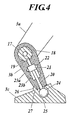
- FIG. 4 and FIG. 5 are conceptual cross-section views showing the joint structure of the B section shown in FIG. 1 .
- the joint structure is composed so that the upper leg section (block) 3a, lower leg section (block) 3b and foot section (block) 3c are integrally connected so as to operate integrally.
- a support shaft 17 is provided on a bottom edge section of the upper leg section 3a.
- a later-described concave section 19 to accommodate a shaft 20 is formed on the support shaft 17.
- a bearing 18 is provided on the lower leg section 3b. Then, the support shaft 17 of the upper leg section 3a is rotatably fitted in the bearing 18.
- a shaft 20 provided to the ball portion 24 composing one side of a ball joint is provided in the lower leg section 3b with the shaft 20 inserted in the shaft hole.
- the shaft 20 can move in the shaft line direction.
- a large diameter stopper 21 is formed on the circumferential face of the shaft 20.
- a circular projection (engaging section) 22 is formed on the circumferential face of the stopper 21.
- the shaft hole extends from the bearing 18 to the foot section 3c.
- An intermediate portion in the shaft line direction of the shaft hole is a large diameter shaft hole portion.
- a first circular concave section (engaging section) 23a and second circular concave section 23b are formed apart in the large diameter shaft hole portion at two points in the shaft line direction.
- the state where the projection 22 of the shaft 20 is fitted in the first circular concave section 23a is the proper position.
- the proper position is the position taken by the robot toy 1 when it is in its original form.
- the ball portion 24 takes the "predetermined position" described in claim 1.
- a portion of the circumferential wall of the shaft hole from the first circular concave section 23a to the second circular concave section 23b has elasticity and enables the shaft 20 to move.
- a ball shaped bearing (ball shaped accommodating section) 25 composing the other side of the ball joint is formed in the foot section 3c.
- the ball portion 24 is accommodated in the ball shaped bearing 25.
- a claw (engaging section) 27 is provided on the ankle of the foot section 3c.
- a notch (engaging section) 26 which can be engaged with the claw 27 is formed in the lower leg section 3b. Then, when the shaft 20 is in the proper position, the claw 27 and the notch 26 are engaged to each other to fix the ankle.
- the foot section 3c can be separated from the lower leg section 3b.
- the claw 27 of the foot section 3c is removed from the notch 26 of the lower leg section 3b, and the upper edge section of the shaft 20 is removed from the concave section 19 of the support shaft 17 of the upper leg section 3a.
- the projection 22 of the shaft 20 reaches the second circular concave section 23b of the lower leg section 3b, it is stopped there.
- the lower leg section 3b can be rotated with respect to the upper leg section 3a, and as shown in FIG. 5 with alternate long and two short dashed line, the position of the foot section 3c can be moved in a free direction with respect to the ball 24.
- leg section 3 of the present invention is shown, however, application is not limited to the leg section 3 and can be applied to other parts such as an arm section, head section, tail section, etc.
- the engaging section can be composed of a cylindrical body provided on a first block and a fitting section provided on a second block to fit to an outer side of the cylindrical body, and the ball portion can be provided to project from a tip of the cylindrical body.
- a joint structure of a toy comprising:
- the ball portion is structured as a head of an eccentric pin projected at an eccentric position of a rotating body provided on the first block; and the engaging section includes:
- the present invention can be used in a part where an eccentric rotating movement is changed to a swinging movement, for example between a body section and a leg section of a robot toy representing a dinosaur, and the leg section with respect to the body section can be in a state other than the original state of the toy.
- the joint structure of the toy further comprises:
- the present invention can be used in a part where three blocks are connected in a line, for example, a leg section or an arm section, and each portion of the leg section and the arm section can be in a state other than the original state of the toy.
- rotating power can be transmitted from the cylindrical body to the second block.
- the first block and the second block are connected to each other in a predetermined position, and when the toy is used as a figure, the first block is connected to the second block only by a ball joint to enable the second block to take a free position.
Landscapes
- Toys (AREA)
Applications Claiming Priority (1)
| Application Number | Priority Date | Filing Date | Title |
|---|---|---|---|
| JP2008100123A JP2009247656A (ja) | 2008-04-08 | 2008-04-08 | 玩具の関節構造 |
Publications (1)
| Publication Number | Publication Date |
|---|---|
| EP2108418A1 true EP2108418A1 (de) | 2009-10-14 |
Family
ID=40942492
Family Applications (1)
| Application Number | Title | Priority Date | Filing Date |
|---|---|---|---|
| EP09156603A Withdrawn EP2108418A1 (de) | 2008-04-08 | 2009-03-30 | Gelenkstruktur für ein Spielzeug |
Country Status (4)
| Country | Link |
|---|---|
| US (1) | US20090253348A1 (de) |
| EP (1) | EP2108418A1 (de) |
| JP (1) | JP2009247656A (de) |
| CN (1) | CN101554532A (de) |
Cited By (1)
| Publication number | Priority date | Publication date | Assignee | Title |
|---|---|---|---|---|
| EP2942092A1 (de) * | 2014-05-07 | 2015-11-11 | Bandai Co., Ltd. | Modell |
Families Citing this family (11)
| Publication number | Priority date | Publication date | Assignee | Title |
|---|---|---|---|---|
| CN101780337B (zh) * | 2010-03-25 | 2013-01-02 | 王代囊 | 玩具的壳体结构 |
| JP5148003B1 (ja) * | 2012-05-16 | 2013-02-20 | 株式会社バンダイ | 人形玩具の関節構造 |
| WO2018029450A1 (en) * | 2016-08-11 | 2018-02-15 | Ironburg Inventions Limited | Input apparatus for a computer |
| JP6745717B2 (ja) * | 2016-12-28 | 2020-08-26 | 株式会社バンダイ | 人形玩具の手首関節構造及び人形玩具 |
| KR102080992B1 (ko) * | 2018-07-03 | 2020-05-22 | 주식회사 초이락컨텐츠팩토리 | 액션 피규어 |
| JP6731029B2 (ja) * | 2018-11-16 | 2020-07-29 | 株式会社バンダイ | 人型玩具 |
| JP6818824B2 (ja) * | 2019-08-02 | 2021-01-20 | 株式会社バンダイ | 人形体の足首の関節構造および人形体 |
| JP7090138B2 (ja) * | 2020-11-13 | 2022-06-23 | 株式会社バンダイ | 腕構造及び人型玩具 |
| JP7038236B1 (ja) * | 2021-01-29 | 2022-03-17 | 株式会社バンダイ | 玩具部品、人形玩具、及び、カバー部材 |
| USD968530S1 (en) * | 2021-06-21 | 2022-11-01 | Shenzhen Dabosi Industrial Co., Ltd. | Dinosaur toy set |
| USD981497S1 (en) * | 2022-06-21 | 2023-03-21 | Guangzhou Xinyi Business Technology Co., Ltd. | Inflatable toy |
Citations (4)
| Publication number | Priority date | Publication date | Assignee | Title |
|---|---|---|---|---|
| GB190923277A (en) * | 1909-10-12 | 1910-02-17 | Albert Day | Improvements in or relating to the Arms of Display Busts or Stands for Dressmakers' and other uses. |
| US5423708A (en) * | 1994-08-15 | 1995-06-13 | Allen; Roger D. | Multi-legged, walking toy robot |
| JP2003265870A (ja) | 2002-03-12 | 2003-09-24 | Yuukashiya:Kk | 二足歩行玩具駆動モジュール |
| US20060178081A1 (en) * | 2005-02-10 | 2006-08-10 | Parviz Daftari | Magnetic joints and toy figurines made therefrom |
-
2008
- 2008-04-08 JP JP2008100123A patent/JP2009247656A/ja active Pending
-
2009
- 2009-03-30 EP EP09156603A patent/EP2108418A1/de not_active Withdrawn
- 2009-03-31 US US12/385,159 patent/US20090253348A1/en not_active Abandoned
- 2009-04-08 CN CNA2009101340635A patent/CN101554532A/zh active Pending
Patent Citations (4)
| Publication number | Priority date | Publication date | Assignee | Title |
|---|---|---|---|---|
| GB190923277A (en) * | 1909-10-12 | 1910-02-17 | Albert Day | Improvements in or relating to the Arms of Display Busts or Stands for Dressmakers' and other uses. |
| US5423708A (en) * | 1994-08-15 | 1995-06-13 | Allen; Roger D. | Multi-legged, walking toy robot |
| JP2003265870A (ja) | 2002-03-12 | 2003-09-24 | Yuukashiya:Kk | 二足歩行玩具駆動モジュール |
| US20060178081A1 (en) * | 2005-02-10 | 2006-08-10 | Parviz Daftari | Magnetic joints and toy figurines made therefrom |
Cited By (2)
| Publication number | Priority date | Publication date | Assignee | Title |
|---|---|---|---|---|
| EP2942092A1 (de) * | 2014-05-07 | 2015-11-11 | Bandai Co., Ltd. | Modell |
| US9511301B2 (en) | 2014-05-07 | 2016-12-06 | Bandai Co., Ltd. | Model |
Also Published As
| Publication number | Publication date |
|---|---|
| CN101554532A (zh) | 2009-10-14 |
| JP2009247656A (ja) | 2009-10-29 |
| US20090253348A1 (en) | 2009-10-08 |
Similar Documents
| Publication | Publication Date | Title |
|---|---|---|
| EP2108418A1 (de) | Gelenkstruktur für ein Spielzeug | |
| KR100366473B1 (ko) | 신축형 진공 청소기 흡입관 | |
| JP2012061111A (ja) | 人形体の関節構造 | |
| JP2010501385A (ja) | 特に航空機における構造部分の着脱可能な連結のための装置および方法 | |
| JP2020534110A (ja) | 注射器の注射針挿入機構 | |
| JP2001083964A (ja) | オルゴール装置 | |
| JPWO2020129442A1 (ja) | 操作装置 | |
| JP2013542884A (ja) | 車両シートの調節装置用自動ロック段階的切替機構 | |
| JP2005306106A (ja) | シフトレバー装置 | |
| JP3156463U (ja) | 人形体 | |
| JP2002002455A (ja) | ワイパ装置におけるアームヘッドのカバー体 | |
| CN112826636B (zh) | 人工晶体推注器 | |
| JP2009162048A (ja) | ヒンジ、ヒンジ本体 | |
| JP6475154B2 (ja) | 押出しラッチ装置 | |
| JP5477986B1 (ja) | 玩具体における連結機構、玩具体および人形体 | |
| JP5106466B2 (ja) | 係止具および係止具を用いた係止構造ならびに係止具を用いたコンテナ | |
| JP2554195B2 (ja) | 取手装置 | |
| JP2008143383A (ja) | シートトラックのロック解除機構 | |
| JP2004033316A (ja) | 電動歯ブラシ | |
| JP2010125955A (ja) | 車両用スライドレール装置 | |
| JP5390313B2 (ja) | シートトラック装置のハンドル保持構造及び回動操作部材の保持構造 | |
| JP2003237552A (ja) | 足踏みパーキングブレーキ装置 | |
| JP2012524218A (ja) | ラインガイドデバイス用クロスビーム | |
| JP5297367B2 (ja) | 肘掛ユニット | |
| JP2022186074A (ja) | 車両用ドアハンドル装置 |
Legal Events
| Date | Code | Title | Description |
|---|---|---|---|
| PUAI | Public reference made under article 153(3) epc to a published international application that has entered the european phase |
Free format text: ORIGINAL CODE: 0009012 |
|
| AK | Designated contracting states |
Kind code of ref document: A1 Designated state(s): AT BE BG CH CY CZ DE DK EE ES FI FR GB GR HR HU IE IS IT LI LT LU LV MC MK MT NL NO PL PT RO SE SI SK TR |
|
| AX | Request for extension of the european patent |
Extension state: AL BA RS |
|
| AKX | Designation fees paid | ||
| REG | Reference to a national code |
Ref country code: DE Ref legal event code: 8566 |
|
| STAA | Information on the status of an ep patent application or granted ep patent |
Free format text: STATUS: THE APPLICATION IS DEEMED TO BE WITHDRAWN |
|
| 18D | Application deemed to be withdrawn |
Effective date: 20100415 |