EP2107170B1 - Hydraulische antriebsanordnung für eine zivilbau- oder erdbewegungsmaschine. - Google Patents
Hydraulische antriebsanordnung für eine zivilbau- oder erdbewegungsmaschine. Download PDFInfo
- Publication number
- EP2107170B1 EP2107170B1 EP09159713A EP09159713A EP2107170B1 EP 2107170 B1 EP2107170 B1 EP 2107170B1 EP 09159713 A EP09159713 A EP 09159713A EP 09159713 A EP09159713 A EP 09159713A EP 2107170 B1 EP2107170 B1 EP 2107170B1
- Authority
- EP
- European Patent Office
- Prior art keywords
- control valve
- valve
- reserve
- actuator
- directional control
- Prior art date
- Legal status (The legal status is an assumption and is not a legal conclusion. Google has not performed a legal analysis and makes no representation as to the accuracy of the status listed.)
- Expired - Lifetime
Links
- 238000010276 construction Methods 0.000 title claims description 30
- 238000011144 upstream manufacturing Methods 0.000 claims description 8
- 230000001276 controlling effect Effects 0.000 description 21
- 238000010586 diagram Methods 0.000 description 19
- 230000000875 corresponding effect Effects 0.000 description 11
- 230000007935 neutral effect Effects 0.000 description 11
- 238000011109 contamination Methods 0.000 description 3
- 230000007423 decrease Effects 0.000 description 3
- 230000002596 correlated effect Effects 0.000 description 2
- 230000000694 effects Effects 0.000 description 2
- 238000001514 detection method Methods 0.000 description 1
- 238000004519 manufacturing process Methods 0.000 description 1
- 230000002265 prevention Effects 0.000 description 1
Images


Classifications
-
- E—FIXED CONSTRUCTIONS
- E02—HYDRAULIC ENGINEERING; FOUNDATIONS; SOIL SHIFTING
- E02F—DREDGING; SOIL-SHIFTING
- E02F9/00—Component parts of dredgers or soil-shifting machines, not restricted to one of the kinds covered by groups E02F3/00 - E02F7/00
- E02F9/20—Drives; Control devices
-
- E—FIXED CONSTRUCTIONS
- E02—HYDRAULIC ENGINEERING; FOUNDATIONS; SOIL SHIFTING
- E02F—DREDGING; SOIL-SHIFTING
- E02F9/00—Component parts of dredgers or soil-shifting machines, not restricted to one of the kinds covered by groups E02F3/00 - E02F7/00
- E02F9/20—Drives; Control devices
- E02F9/22—Hydraulic or pneumatic drives
- E02F9/2264—Arrangements or adaptations of elements for hydraulic drives
- E02F9/2267—Valves or distributors
-
- E—FIXED CONSTRUCTIONS
- E02—HYDRAULIC ENGINEERING; FOUNDATIONS; SOIL SHIFTING
- E02F—DREDGING; SOIL-SHIFTING
- E02F9/00—Component parts of dredgers or soil-shifting machines, not restricted to one of the kinds covered by groups E02F3/00 - E02F7/00
- E02F9/20—Drives; Control devices
- E02F9/22—Hydraulic or pneumatic drives
- E02F9/2221—Control of flow rate; Load sensing arrangements
- E02F9/2239—Control of flow rate; Load sensing arrangements using two or more pumps with cross-assistance
- E02F9/2242—Control of flow rate; Load sensing arrangements using two or more pumps with cross-assistance including an electronic controller
-
- E—FIXED CONSTRUCTIONS
- E02—HYDRAULIC ENGINEERING; FOUNDATIONS; SOIL SHIFTING
- E02F—DREDGING; SOIL-SHIFTING
- E02F9/00—Component parts of dredgers or soil-shifting machines, not restricted to one of the kinds covered by groups E02F3/00 - E02F7/00
- E02F9/20—Drives; Control devices
- E02F9/22—Hydraulic or pneumatic drives
- E02F9/2264—Arrangements or adaptations of elements for hydraulic drives
- E02F9/2271—Actuators and supports therefor and protection therefor
-
- E—FIXED CONSTRUCTIONS
- E02—HYDRAULIC ENGINEERING; FOUNDATIONS; SOIL SHIFTING
- E02F—DREDGING; SOIL-SHIFTING
- E02F9/00—Component parts of dredgers or soil-shifting machines, not restricted to one of the kinds covered by groups E02F3/00 - E02F7/00
- E02F9/20—Drives; Control devices
- E02F9/22—Hydraulic or pneumatic drives
- E02F9/2278—Hydraulic circuits
- E02F9/2292—Systems with two or more pumps
Landscapes
- Engineering & Computer Science (AREA)
- Mining & Mineral Resources (AREA)
- Civil Engineering (AREA)
- General Engineering & Computer Science (AREA)
- Structural Engineering (AREA)
- Physics & Mathematics (AREA)
- Fluid Mechanics (AREA)
- Fluid-Pressure Circuits (AREA)
- Operation Control Of Excavators (AREA)
Claims (3)
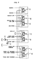
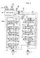
- Hydraulisches Antriebssystem für eine Hoch- und Tiefbau- oder Baumaschine, wobei das System ausgestattet ist mit einer ersten Hydraulikpumpe (1) und einer zweiten Hydraulikpumpe (2), einer ersten Steuerventilgruppe (15a), die mit der ersten Hydraulikpumpe (1) verbunden ist und and ihrer am weitesten stromabwärts liegenden Seite mit einem Bypass-Ein/Aus-Ventil (7) ausgestattet ist, welches eine offene Position und eine geschlossene Position zum wahlweisen Herstellen oder Unterdrücken eines Bypassdurchgangs, und eine zweite Steuerventilgruppe (15b), die mit der zweiten Hydraulikpumpe (2) verbunden ist und mehrere Richtungssteuerungsventile (8, 9, 10, 11, 13) umfasst, die ein ReserveRichtungssteuerungsventil (11) umfasst,
dadurch gekennzeichnet, dass das System ausgestattet ist mit:einer Verbindungsleitung (13), die eine am weitesten stromaufwärts liegende Seite der ersten Steuerventilgruppe (15a) mit einer Versorgungsleitung mit dem Reserverichtungssteuerungsventil (11) verbindet,ein Kombinationssteuerventil (14) mit einer offenen Position und einer geschlossenen Position, um wahlweise eine Verbindung der Verbindungsleitung (13) herzustellen oder zu unterbrechen,ein Verknüpfungs-Steuerungsmittel (26, 27), welches eine Betätigung zum Umschalten des Kombinationssteuerungsventils (14) in die offene Position und des Bypass-Ein/Aus-Ventils (17) in die geschlossene Position im Zusammenhang mit einer Umschaltbetätigung eines Reservesteuerungsventils (14) zum Umschalten des Reserverichtungssteuerungsventils (11) ermöglicht,ein selektives Umschaltmittel (28a), das wahlweise einen von mehreren Zuständen annehmen kann, in welchen die Umschaltbetätigung des Kombinationssteuerungsventils (14) in die offene Position durch das Verknüpfungs-Steuerungsmittel (26, 27) möglich ist, sowie einen anderen Zustand, in welchem der Umschaltvorgang des Kombinationssteuerungsventils (14) in die offene Position mittels des Verknüpfungs-Steuerungsmittels (26, 27) unmöglich ist, undeinem Ventilöffnungsflächensteuerungsmittel (40, 50, 51, 52) zur Steuerung des Antriebs des Kombinationssteuerungsventils (14) derart, dass dann, wenn ein spezielles Richtungssteuerungsventil (3, 5, 6) in der ersten Steuerventilgruppe (15a) zur Steuerung des Antriebs eines Aktuators, auf welchen ein Lastdruck ausgeübt werden kann, der größer als ein Lastdruck eines von dem Reserverichtungssteuerungsventil (11) gesteuerten Aktuators ist, gemeinsam mit einem Umschaltvorgang des Reserverichtungssteuerungsventils (11) durch die Reservesteuerungsvorrichtung (24) betätigt wird, eine Ventilöffnungsfläche des Kombinationssteuerungsventils (14) auf eine vorgegebene kleine Ventilöffnungsfläche geändert wird und das Verknüpfungssteuerungsmittel (25, 27) dahingehend wirkt, dass das Bypass-Ein/Aus-Ventil (17) in der geschlossenen Position gehalten wird, wenn eine Umschaltbetätigung des Reservesteuerungsventils (24) erfolgt, selbst wenn das spezielle Richtungssteuerungsventil (3, 5, 6) betätigt wird und die Öffnungsfläche des Kombinationssteuerungsventils (14) durch das Ventilöffnungsflächensteuermittel (40, 50, 51, 52) verringert wurde. - Hydraulisches Antriebssystem nach Anspruch 1, wobei das Reserverichtungssteuerungsventil (11) ein hydraulisch betätigtes Pilotventil umfasst, Die Reservesteuervorrichtung eine pilotbetätigte Steuervorrichtung zur Ausgabe eines Pilotdrucks zum Umschalten des Reserverichtungssteuerungsventils (11) umfasst und das Kombinationssteuerungsventil (14) und das Bypass-Ein/Aus-Ventil (7) jeweils hydraulisch betätigte Pilotventile umfassen,
das Verknüpfungs-Steuerungsmittel (26, 27) ein Shuttle-Ventil (26) umfasst, welches einen von der Reservesteuerungsvorrichtung (24) ausgegebenen Pilotdruck detektieren kann und diesen Pilotdruck als ein Drucksignal zum Umschalten des Kombinationssteuerungsventils (14) in die offene Position und des Bypass-Ein/Aus-Ventils (7) in die geschlossene Position ausgeben kann, und eine Pilotleitung (27), welche das Shuttle-Ventil (26) mit den jeweiligen Antriebsbereichen des Kombinationssteuerungsventils (14) und des Bypass-Ein/Aus-Ventils (7) verbindet, und
das selektive Umschaltmittel ein selektives Steuerventil (28) umfasst, welches in einem ersten Teil der Pilotleitung (27) angeordnet ist, welcher das Shuttle-Ventil (26) mit dem Antriebsbereich des Kombinationssteuerungsventils (14) verbindet und das wahlweise entweder einen ersten Zustand annehmen kann, in welchem der von dem Shuttle-Ventil (26) ausgegebene Pilotdruck in dem Antriebsbereich des Verbindungssteuerungsventils (14) eingespeist wird sowie einen zweiten Zustand, in welchem der von dem Shuttle-Ventil (26) ausgegebene Pilotdruck nicht in den Antriebsbereich des Kombinationssteuerungsventils (14) eingespeist werden kann. - Hydraulisches Antriebssystem nach Anspruch 2, wobei:das selektive Steuerventil (28) ein Spulenventil umfasst; unddas Ventilöffnungsflächensteuermittel umfasst:ein spezifisches Betätigungs-Detektionsmittel (50, 51, 52) zur Detektion der Betätigung des spezifischen Richtungssteuerungsventils (3, 5, 6), welches in der ersten Steuerventilgruppe (15a) enthalten ist und zum Ausgeben eines elektrischen Signals undeine Steuereinheit (40) zum Durchführen einer vorgegebenen Berechnung auf Grundlage des elektrischen Signals, welches von den spezifischen Betätigungs-Detektionsmittel (50, 51, 52) ausgegeben wurde und zum Ausgeben eines Steuersignals (6), welches den Ergebnissen dieser Berechnungen entspricht, als ein Signal zum Betreiben des selektiven Steuerventils.
Applications Claiming Priority (3)
| Application Number | Priority Date | Filing Date | Title |
|---|---|---|---|
| JP1083399 | 1999-01-19 | ||
| JP29263799A JP3943779B2 (ja) | 1999-01-19 | 1999-10-14 | 土木・建設機械の油圧駆動装置 |
| EP00900432A EP1178157B1 (de) | 1999-01-19 | 2000-01-18 | Hydraulische antriebsanordnung für eine zivilbau- oder erdbewegungsmaschine. |
Related Parent Applications (2)
| Application Number | Title | Priority Date | Filing Date |
|---|---|---|---|
| EP00900432A Division EP1178157B1 (de) | 1999-01-19 | 2000-01-18 | Hydraulische antriebsanordnung für eine zivilbau- oder erdbewegungsmaschine. |
| EP00900432.6 Division | 2000-01-18 |
Publications (4)
| Publication Number | Publication Date |
|---|---|
| EP2107170A2 EP2107170A2 (de) | 2009-10-07 |
| EP2107170A3 EP2107170A3 (de) | 2009-11-11 |
| EP2107170B1 true EP2107170B1 (de) | 2012-03-21 |
| EP2107170B8 EP2107170B8 (de) | 2012-04-25 |
Family
ID=26346178
Family Applications (2)
| Application Number | Title | Priority Date | Filing Date |
|---|---|---|---|
| EP09159713A Expired - Lifetime EP2107170B8 (de) | 1999-01-19 | 2000-01-18 | Hydraulische antriebsanordnung für eine zivilbau- oder erdbewegungsmaschine. |
| EP00900432A Expired - Lifetime EP1178157B1 (de) | 1999-01-19 | 2000-01-18 | Hydraulische antriebsanordnung für eine zivilbau- oder erdbewegungsmaschine. |
Family Applications After (1)
| Application Number | Title | Priority Date | Filing Date |
|---|---|---|---|
| EP00900432A Expired - Lifetime EP1178157B1 (de) | 1999-01-19 | 2000-01-18 | Hydraulische antriebsanordnung für eine zivilbau- oder erdbewegungsmaschine. |
Country Status (7)
| Country | Link |
|---|---|
| US (1) | US6619037B1 (de) |
| EP (2) | EP2107170B8 (de) |
| JP (1) | JP3943779B2 (de) |
| KR (1) | KR100441715B1 (de) |
| CN (1) | CN1143923C (de) |
| DE (1) | DE60045683D1 (de) |
| WO (1) | WO2000043601A1 (de) |
Families Citing this family (29)
| Publication number | Priority date | Publication date | Assignee | Title |
|---|---|---|---|---|
| JP4565759B2 (ja) * | 2001-03-19 | 2010-10-20 | カヤバ工業株式会社 | 油圧制御装置 |
| KR100923396B1 (ko) | 2004-02-23 | 2009-10-23 | 현대중공업 주식회사 | 굴삭기 작업장치의 가변우선 시스템 |
| KR100594856B1 (ko) | 2005-03-08 | 2006-06-30 | 볼보 컨스트럭션 이키프먼트 홀딩 스웨덴 에이비 | 복합조작이 가능한 합류시스템 |
| JP4781708B2 (ja) * | 2005-04-21 | 2011-09-28 | 株式会社クボタ | 作業車輌の油圧システム |
| KR101250083B1 (ko) * | 2005-12-29 | 2013-04-02 | 두산인프라코어 주식회사 | 로그로더 굴삭기의 유압제어장치 |
| JP4232784B2 (ja) * | 2006-01-20 | 2009-03-04 | コベルコ建機株式会社 | 作業機械の油圧制御装置 |
| KR101063126B1 (ko) | 2006-02-17 | 2011-09-07 | 현대중공업 주식회사 | 소형 굴삭기의 유량배분 장치 |
| US9074352B2 (en) | 2006-03-27 | 2015-07-07 | John R. Ramun | Universal control scheme for mobile hydraulic equipment and method for achieving the same |
| EP1999316A2 (de) * | 2006-03-27 | 2008-12-10 | John R. Ramun | Universelles steuerungsschema für eine mobile hydraulische vorrichtung und verfahren zu dessen erhalt |
| KR101637575B1 (ko) * | 2009-12-24 | 2016-07-07 | 두산인프라코어 주식회사 | 건설기계의 유압제어장치 |
| JP5779256B2 (ja) * | 2010-12-27 | 2015-09-16 | ボルボ コンストラクション イクイップメント アーベー | 建設機械の油圧システム |
| JP5481408B2 (ja) * | 2011-02-14 | 2014-04-23 | 日立建機株式会社 | 作業機械の油圧駆動装置 |
| US20140158235A1 (en) * | 2011-08-09 | 2014-06-12 | Volvo Construction Equipment Ab | Hydraulic control system for construction machinery |
| JP5803587B2 (ja) * | 2011-11-09 | 2015-11-04 | コベルコ建機株式会社 | 建設機械の油圧回路 |
| CN102536932A (zh) * | 2012-01-11 | 2012-07-04 | 中联重科股份有限公司 | 压缩垃圾车及其液压系统 |
| JP5901378B2 (ja) * | 2012-03-23 | 2016-04-06 | Kyb株式会社 | 走行制御バルブ |
| JP5778086B2 (ja) * | 2012-06-15 | 2015-09-16 | 住友建機株式会社 | 建設機械の油圧回路及びその制御装置 |
| JP5758348B2 (ja) * | 2012-06-15 | 2015-08-05 | 住友建機株式会社 | 建設機械の油圧回路 |
| JP5985276B2 (ja) * | 2012-07-02 | 2016-09-06 | 住友建機株式会社 | 建設機械の油圧回路及びその制御装置 |
| JP5978056B2 (ja) * | 2012-08-07 | 2016-08-24 | 住友建機株式会社 | 建設機械の油圧回路及びその制御装置 |
| JP6283195B2 (ja) * | 2012-12-04 | 2018-02-21 | 住友精密工業株式会社 | 脚揚降用電動油圧アクチュエータシステム |
| JP2014173614A (ja) * | 2013-03-06 | 2014-09-22 | Caterpillar Sarl | 油圧装置の合流回路 |
| JP6196499B2 (ja) * | 2013-08-20 | 2017-09-13 | ナブテスコ株式会社 | 建設機械の多連方向切換弁 |
| JP6220228B2 (ja) * | 2013-10-31 | 2017-10-25 | 川崎重工業株式会社 | 建設機械の油圧駆動システム |
| CN104564868B (zh) * | 2014-11-24 | 2017-03-01 | 徐州重型机械有限公司 | 合流控制系统、方法及起重机 |
| JP6569852B2 (ja) | 2015-06-25 | 2019-09-04 | ヤンマー株式会社 | 油圧装置 |
| JP6564754B2 (ja) * | 2016-09-30 | 2019-08-21 | 日立建機株式会社 | 土木・建設機械 |
| JP6940403B2 (ja) * | 2017-12-28 | 2021-09-29 | 日立建機株式会社 | 作業機械の油圧駆動装置 |
| US11624452B2 (en) | 2019-04-12 | 2023-04-11 | Barko Hydraulics, LLC | System for adjusting rate of spool centering in a pilot-controlled hydraulic spool valve |
Family Cites Families (16)
| Publication number | Priority date | Publication date | Assignee | Title |
|---|---|---|---|---|
| DE1952034A1 (de) * | 1969-10-15 | 1971-04-22 | Linde Ag | Steuereinrichtung fuer eine hydraulische Anlage und Ventil hierzu |
| JPS58149403A (ja) * | 1982-02-27 | 1983-09-05 | Kayaba Ind Co Ltd | 油圧制御回路とその多連切換弁 |
| EP0235545B1 (de) * | 1986-01-25 | 1990-09-12 | Hitachi Construction Machinery Co., Ltd. | Hydraulisches Antriebssystem |
| WO1989012756A1 (en) * | 1988-06-17 | 1989-12-28 | Kabushiki Kaisha Kobe Seiko Sho | Fluid control mechanism for power shovels |
| JP2642972B2 (ja) | 1988-12-21 | 1997-08-20 | 東芝機械株式会社 | アタッチメント用切換弁の油圧回路 |
| JPH086354B2 (ja) * | 1989-10-31 | 1996-01-24 | 株式会社小松製作所 | 油圧式掘削機の油圧回路 |
| JP2716607B2 (ja) * | 1991-09-09 | 1998-02-18 | 日立建機株式会社 | 建設機械の油圧回路 |
| JPH05187041A (ja) * | 1992-01-09 | 1993-07-27 | Shin Caterpillar Mitsubishi Ltd | 建設機械車輌の減速防止方法 |
| JP2892939B2 (ja) * | 1994-06-28 | 1999-05-17 | 日立建機株式会社 | 油圧掘削機の油圧回路装置 |
| JP3013225B2 (ja) * | 1995-01-11 | 2000-02-28 | 新キャタピラー三菱株式会社 | 吊り作業制御装置 |
| JP3153118B2 (ja) * | 1996-02-01 | 2001-04-03 | 新キャタピラー三菱株式会社 | 油圧式作業機械の油圧回路 |
| KR0185493B1 (ko) * | 1996-03-30 | 1999-04-01 | 토니헬샴 | 중장비용 유량 합류장치 |
| JP3730715B2 (ja) * | 1996-07-11 | 2006-01-05 | 東芝機械株式会社 | 油圧制御弁装置 |
| JP3425844B2 (ja) * | 1996-09-30 | 2003-07-14 | コベルコ建機株式会社 | 油圧ショベル |
| JP3764249B2 (ja) * | 1997-06-18 | 2006-04-05 | 株式会社加藤製作所 | 建設車両のアクチュエータ作動回路 |
| JPH1116174A (ja) | 1997-06-20 | 1999-01-22 | Sony Corp | 光ディスク装置 |
-
1999
- 1999-10-14 JP JP29263799A patent/JP3943779B2/ja not_active Expired - Lifetime
-
2000
- 2000-01-18 US US09/889,612 patent/US6619037B1/en not_active Expired - Lifetime
- 2000-01-18 EP EP09159713A patent/EP2107170B8/de not_active Expired - Lifetime
- 2000-01-18 CN CNB00804287XA patent/CN1143923C/zh not_active Expired - Lifetime
- 2000-01-18 EP EP00900432A patent/EP1178157B1/de not_active Expired - Lifetime
- 2000-01-18 DE DE60045683T patent/DE60045683D1/de not_active Expired - Lifetime
- 2000-01-18 WO PCT/JP2000/000201 patent/WO2000043601A1/ja active IP Right Grant
- 2000-01-18 KR KR10-2001-7009019A patent/KR100441715B1/ko active IP Right Grant
Also Published As
| Publication number | Publication date |
|---|---|
| JP2000273916A (ja) | 2000-10-03 |
| KR20010092781A (ko) | 2001-10-26 |
| CN1143923C (zh) | 2004-03-31 |
| EP2107170B8 (de) | 2012-04-25 |
| KR100441715B1 (ko) | 2004-07-23 |
| EP1178157B1 (de) | 2011-03-02 |
| WO2000043601A1 (fr) | 2000-07-27 |
| CN1341185A (zh) | 2002-03-20 |
| JP3943779B2 (ja) | 2007-07-11 |
| EP2107170A2 (de) | 2009-10-07 |
| EP1178157A1 (de) | 2002-02-06 |
| DE60045683D1 (de) | 2011-04-14 |
| US6619037B1 (en) | 2003-09-16 |
| EP1178157A4 (de) | 2008-05-07 |
| EP2107170A3 (de) | 2009-11-11 |
Similar Documents
| Publication | Publication Date | Title |
|---|---|---|
| EP2107170B1 (de) | Hydraulische antriebsanordnung für eine zivilbau- oder erdbewegungsmaschine. | |
| US6799424B2 (en) | Hydraulic circuit | |
| EP1790859B1 (de) | Hydraulische Steuerung für eine Bearbeitungsmaschine | |
| EP1760326B1 (de) | Hydraulische Steuervorrichtung für eine Baumaschine | |
| EP0235545A2 (de) | Hydraulisches Antriebssystem | |
| EP1811185A2 (de) | Hydraulische Steuervorrichtung für eine Baumaschine | |
| US6176126B1 (en) | Engine speed control system for construction machine | |
| US11649610B2 (en) | Hydraulic system of construction machine | |
| EP1970571B1 (de) | Hydraulikschaltung einer Baumaschine | |
| US5680759A (en) | Straight travelling apparatus for heavy construction equipment | |
| EP0709579A2 (de) | Vorrichtung für Geradeausfahrt bei schweren Baumaschinen | |
| JP2002265187A (ja) | 旋回制御装置 | |
| JP2555287B2 (ja) | 油圧制御装置 | |
| JPH0449196A (ja) | クレーン用油圧回路 | |
| JP3142640B2 (ja) | 油圧作業機の油圧回路 | |
| JPH09158903A (ja) | 油圧アクチュエータの流量制御装置 | |
| KR100240081B1 (ko) | 중장비용 선회모터의 릴리이프압력 가변제어장치 | |
| JPH02261903A (ja) | クローズドセンタ・ロードセンシングシステムにおける油圧回路 | |
| JP5366485B2 (ja) | 建設機械の油圧制御装置 | |
| JP2000220602A (ja) | 建設機械の油圧回路 | |
| JPH09111799A (ja) | 作業機の干渉防止制御回路装置 | |
| JPH10131237A (ja) | 建設機械の制御回路 | |
| JP2011236971A (ja) | 作業機械の油圧システム | |
| JPH10218557A (ja) | 作業機械の油圧回路 | |
| JPH10281112A (ja) | 流体制御方法およびその装置 |
Legal Events
| Date | Code | Title | Description |
|---|---|---|---|
| PUAI | Public reference made under article 153(3) epc to a published international application that has entered the european phase |
Free format text: ORIGINAL CODE: 0009012 |
|
| 17P | Request for examination filed |
Effective date: 20090507 |
|
| AC | Divisional application: reference to earlier application |
Ref document number: 1178157 Country of ref document: EP Kind code of ref document: P |
|
| AK | Designated contracting states |
Kind code of ref document: A2 Designated state(s): AT BE CH CY DE DK ES FI FR GB GR IE IT LI LU MC NL PT SE |
|
| PUAL | Search report despatched |
Free format text: ORIGINAL CODE: 0009013 |
|
| AK | Designated contracting states |
Kind code of ref document: A3 Designated state(s): AT BE CH CY DE DK ES FI FR GB GR IE IT LI LU MC NL PT SE |
|
| RIN1 | Information on inventor provided before grant (corrected) |
Inventor name: HIRATA, TOICHI Inventor name: TOYOOKA, TSUKASA Inventor name: NAKAMURA, TSUYOSHI Inventor name: ISHIKAWA, KOUJI Inventor name: NISHIMURA, MASAO Inventor name: SUGIYAMA, GENROKU |
|
| 17Q | First examination report despatched |
Effective date: 20100526 |
|
| RBV | Designated contracting states (corrected) |
Designated state(s): DE FR GB IT SE |
|
| RTI1 | Title (correction) |
Free format text: HYDRAULIC DRIVE SYSTEM FOR A CIVIL ENGINEERING OR CONSTRUCTION MACHINE. |
|
| GRAP | Despatch of communication of intention to grant a patent |
Free format text: ORIGINAL CODE: EPIDOSNIGR1 |
|
| GRAS | Grant fee paid |
Free format text: ORIGINAL CODE: EPIDOSNIGR3 |
|
| GRAA | (expected) grant |
Free format text: ORIGINAL CODE: 0009210 |
|
| AC | Divisional application: reference to earlier application |
Ref document number: 1178157 Country of ref document: EP Kind code of ref document: P |
|
| AK | Designated contracting states |
Kind code of ref document: B1 Designated state(s): DE FR GB IT SE |
|
| REG | Reference to a national code |
Ref country code: GB Ref legal event code: FG4D |
|
| RAP2 | Party data changed (patent owner data changed or rights of a patent transferred) |
Owner name: HITACHI CONSTRUCTION MACHINERY CO., LTD. |
|
| REG | Reference to a national code |
Ref country code: DE Ref legal event code: R096 Ref document number: 60047020 Country of ref document: DE Effective date: 20120516 |
|
| REG | Reference to a national code |
Ref country code: SE Ref legal event code: TRGR |
|
| PLBE | No opposition filed within time limit |
Free format text: ORIGINAL CODE: 0009261 |
|
| STAA | Information on the status of an ep patent application or granted ep patent |
Free format text: STATUS: NO OPPOSITION FILED WITHIN TIME LIMIT |
|
| 26N | No opposition filed |
Effective date: 20130102 |
|
| REG | Reference to a national code |
Ref country code: DE Ref legal event code: R097 Ref document number: 60047020 Country of ref document: DE Effective date: 20130102 |
|
| REG | Reference to a national code |
Ref country code: FR Ref legal event code: PLFP Year of fee payment: 17 |
|
| REG | Reference to a national code |
Ref country code: FR Ref legal event code: PLFP Year of fee payment: 18 |
|
| REG | Reference to a national code |
Ref country code: FR Ref legal event code: PLFP Year of fee payment: 19 |
|
| PGFP | Annual fee paid to national office [announced via postgrant information from national office to epo] |
Ref country code: FR Payment date: 20181213 Year of fee payment: 20 |
|
| PGFP | Annual fee paid to national office [announced via postgrant information from national office to epo] |
Ref country code: DE Payment date: 20190108 Year of fee payment: 20 Ref country code: IT Payment date: 20190121 Year of fee payment: 20 Ref country code: GB Payment date: 20190116 Year of fee payment: 20 |
|
| PGFP | Annual fee paid to national office [announced via postgrant information from national office to epo] |
Ref country code: SE Payment date: 20190110 Year of fee payment: 20 |
|
| REG | Reference to a national code |
Ref country code: DE Ref legal event code: R071 Ref document number: 60047020 Country of ref document: DE |
|
| REG | Reference to a national code |
Ref country code: GB Ref legal event code: PE20 Expiry date: 20200117 |
|
| REG | Reference to a national code |
Ref country code: SE Ref legal event code: EUG |
|
| PG25 | Lapsed in a contracting state [announced via postgrant information from national office to epo] |
Ref country code: GB Free format text: LAPSE BECAUSE OF EXPIRATION OF PROTECTION Effective date: 20200117 |