EP2107170B1 - Hydraulic drive system for a civil engineering or construction machine. - Google Patents
Hydraulic drive system for a civil engineering or construction machine. Download PDFInfo
- Publication number
- EP2107170B1 EP2107170B1 EP09159713A EP09159713A EP2107170B1 EP 2107170 B1 EP2107170 B1 EP 2107170B1 EP 09159713 A EP09159713 A EP 09159713A EP 09159713 A EP09159713 A EP 09159713A EP 2107170 B1 EP2107170 B1 EP 2107170B1
- Authority
- EP
- European Patent Office
- Prior art keywords
- control valve
- valve
- reserve
- actuator
- directional control
- Prior art date
- Legal status (The legal status is an assumption and is not a legal conclusion. Google has not performed a legal analysis and makes no representation as to the accuracy of the status listed.)
- Expired - Lifetime
Links
- 238000010276 construction Methods 0.000 title claims description 30
- 238000011144 upstream manufacturing Methods 0.000 claims description 8
- 230000001276 controlling effect Effects 0.000 description 21
- 238000010586 diagram Methods 0.000 description 19
- 230000000875 corresponding effect Effects 0.000 description 11
- 230000007935 neutral effect Effects 0.000 description 11
- 238000011109 contamination Methods 0.000 description 3
- 230000007423 decrease Effects 0.000 description 3
- 230000002596 correlated effect Effects 0.000 description 2
- 230000000694 effects Effects 0.000 description 2
- 238000001514 detection method Methods 0.000 description 1
- 238000004519 manufacturing process Methods 0.000 description 1
- 230000002265 prevention Effects 0.000 description 1
Images


Classifications
-
- E—FIXED CONSTRUCTIONS
- E02—HYDRAULIC ENGINEERING; FOUNDATIONS; SOIL SHIFTING
- E02F—DREDGING; SOIL-SHIFTING
- E02F9/00—Component parts of dredgers or soil-shifting machines, not restricted to one of the kinds covered by groups E02F3/00 - E02F7/00
- E02F9/20—Drives; Control devices
-
- E—FIXED CONSTRUCTIONS
- E02—HYDRAULIC ENGINEERING; FOUNDATIONS; SOIL SHIFTING
- E02F—DREDGING; SOIL-SHIFTING
- E02F9/00—Component parts of dredgers or soil-shifting machines, not restricted to one of the kinds covered by groups E02F3/00 - E02F7/00
- E02F9/20—Drives; Control devices
- E02F9/22—Hydraulic or pneumatic drives
- E02F9/2264—Arrangements or adaptations of elements for hydraulic drives
- E02F9/2267—Valves or distributors
-
- E—FIXED CONSTRUCTIONS
- E02—HYDRAULIC ENGINEERING; FOUNDATIONS; SOIL SHIFTING
- E02F—DREDGING; SOIL-SHIFTING
- E02F9/00—Component parts of dredgers or soil-shifting machines, not restricted to one of the kinds covered by groups E02F3/00 - E02F7/00
- E02F9/20—Drives; Control devices
- E02F9/22—Hydraulic or pneumatic drives
- E02F9/2221—Control of flow rate; Load sensing arrangements
- E02F9/2239—Control of flow rate; Load sensing arrangements using two or more pumps with cross-assistance
- E02F9/2242—Control of flow rate; Load sensing arrangements using two or more pumps with cross-assistance including an electronic controller
-
- E—FIXED CONSTRUCTIONS
- E02—HYDRAULIC ENGINEERING; FOUNDATIONS; SOIL SHIFTING
- E02F—DREDGING; SOIL-SHIFTING
- E02F9/00—Component parts of dredgers or soil-shifting machines, not restricted to one of the kinds covered by groups E02F3/00 - E02F7/00
- E02F9/20—Drives; Control devices
- E02F9/22—Hydraulic or pneumatic drives
- E02F9/2264—Arrangements or adaptations of elements for hydraulic drives
- E02F9/2271—Actuators and supports therefor and protection therefor
-
- E—FIXED CONSTRUCTIONS
- E02—HYDRAULIC ENGINEERING; FOUNDATIONS; SOIL SHIFTING
- E02F—DREDGING; SOIL-SHIFTING
- E02F9/00—Component parts of dredgers or soil-shifting machines, not restricted to one of the kinds covered by groups E02F3/00 - E02F7/00
- E02F9/20—Drives; Control devices
- E02F9/22—Hydraulic or pneumatic drives
- E02F9/2278—Hydraulic circuits
- E02F9/2292—Systems with two or more pumps
Definitions
- This invention relates to a hydraulic drive system for a civil engineering or construction machine such as a hydraulic excavator, which is suitable for arrangement in the civil engineering or construction machine and has a first control valve group connected to a first hydraulic pump and including plural directional control valves and a second control valve group connected to a second hydraulic pump and including plural directional control valves.
- JP 2642972 B2 As conventional art of this type, there is, for example, one disclosed in JP 2642972 B2 .
- This conventional art relates to a hydraulic circuit for a civil engineering or construction machine, and is provided with a first hydraulic pump and a second hydraulic pump.
- a first control valve group Connected to the first hydraulic pump is a first control valve group, which is provided on a most downstream side with a bypass on/off valve having an open position and a closed position for selectively maintaining a bypass passage in or out of communication and makes up a single housing including a revolving-controlling directional control valve, an arm-controlling directional control valve, and a travel-controlling directional control valve for one of traveling motors.
- the individual directional control valves in this first control valve group are connected parallel to the first hydraulic pump.
- a second control valve group Connected to the second hydraulic pump is a second control valve group, which makes up another housing including, in addition to a reserve directional control valve as an attachment-controlling directional control valve for controlling an attachment actuator for driving an attachment such as a hydraulic breaker or a hydraulic venchure, a boom-controlling directional control valve, a bucket-controlling directional control valve, and a travel-controlling directional control valve for the other traveling motor.
- the individual directional control valves in this second control valve group, except for the reserve directional control valve, are connected parallel to the second hydraulic pump.
- a communication line is arranged to communicate a delivery line from the first hydraulic pump and a supply line to the reserve directional control valve with each other.
- This communication line is connected at one end thereof to the housing of the first control valve group and at an opposite end thereof to the housing of the second control valve group.
- the communication line is arranged as an external piping outside the respective housings.
- a shuttle valve is also arranged.
- the shuttle valve detects a pilot pressure which serves to change over the reserve directional control valve, and the shuttle valve takes it out as a control pressure for changing over the above-mentioned bypass on/off valve to the closed position.
- the reserve directional control valve When the reserve directional control valve is changed over in the conventional art constructed as described above, its operating pressure is applied as a control pressure to a drive portion of the bypass on/off valve in the first control valve group via the shuttle valve, and the bypass on/off valve is changed over to the closed position. Pressure oil from the first hydraulic pump is, therefore, supplied to the communication line arranged outside the two housings. This pressure oil is supplied further to the reserve directional control valve, and then to the attachment actuator controlled by the reserve directional control valve. Accordingly, the attachment actuator controlled by the reserve directional control valve is driven by the pressure oil from the first hydraulic pump rather than pressure oil from the second hydraulic pump connected to the second control valve group to which the reserve directional control valve belongs.
- the communication line through which the pressure oil from the first hydraulic pump is guided to the reserve directional control valve is a line arranged outside the housings in which the first control valve group and the second control valve group are accommodated, respectively, in other words, is an external line.
- the communication line therefore, tends to become longer, leading to problems that a pressure loss tends to become large and the accuracy of control of attachment actuators tends to drop.
- the above-mentioned communication line is connected at the one end thereof to the housing in which the first control valve group is accommodated and at the opposite end thereof to the housing in which the second control valve group is accommodated. Oil leakage, therefore, tends to occur at both of the connected parts. Occurrence of such oil leakage leads to insufficiency in the amount of oil in the circuit and also to contamination of surrounding equipment with the oil.
- the present invention has been completed in view of the above-described circumstances of the conventional art, and an object of the present invention is to provide a hydraulic drive system for civil engineering or construction machine, which can change the maximum value of the operating speed of an actuator controlled by a reserve directional control valve and can also achieve good combined operation of the actuator, which is controlled by the reserve directional control valve, and an actuator which is controlled by a specific directional control valve belonging to a control valve group without the reserve directional control valve and may be applied with a load pressure higher than a load pressure to the actuator controlled by the reserve directional control valve.
- the present invention also provides in an first aspect thereof a hydraulic drive system for a civil engineering or construction machine, said system being provided with a first hydraulic pump and a second hydraulic pump, a first control valve group connected to the first hydraulic pump, provided on a most downstream side thereof with a bypass on/off valve having an open position and a closed position for selectively maintaining a bypass passage in or out of communication, and a second control valve group connected to the second hydraulic pump and comprised of plural directional control valves including a reserve directional control valve, characterized in that the system is provided with a communication line communicating a most upstream side of the first control valve group with a supply line to the reserve directional control valve, a merge control valve having an open position and a closed position to selectively maintain the communication line in or out of communication, an interlocked control means for permitting an operation to change over the merge control valve to the open position and the bypass on/off valve to the closed position in association with a change-over operation of a reserve control device for changing over the reserve directional control
- the reserve directional control valve is changed over from a neutral position when the reserve control device is operated to operate the actuator controlled by the reserve directional control valve, for example, in a state that the selective change-over moans has boon operated to permit a change-over operation of the merge control valve to the open position by the interlocked control means.
- the interlocked control means is operated to change over the merge control valve and the bypass on/off valve to the open position and the closed position, respectively. Accordingly, the pressure oil from the first hydraulic pump is guided to the supply line to the reserve directional control valve via the merge control valve and the communication line.
- the pressure oil from the first hydraulic pump and the pressure oil from the second hydraulic pump are both supplied to the reserve directional control valve and further to the actuator controlled by the reserve directional control valve.
- the actuator controlled by the reserve directional control valve can be operated at a fast speed accordingly.
- the valve opening area control means operates such that the valve opening area of the merge control valve is controlled to the predetermined small valve open area.
- the merge control valve is controlled such that the supply of the pressure oil from the first hydraulic pump to the reserve directional control valve via the merge control valve is reduced, and therefore, a sufficient portion of the pressure oil from the first hydraulic pump can be supplied to the specific directional control valve.
- the actuator controlled by the specific directional control valve in other words, the actuator to which a load pressure higher than that to be applied to the actuator controlled by the reserve directional control valve may be applied can be driven together with the actuator controlled by the reserve directional control valve, thereby making it possible to achieve a good combined operation of these actuators.
- the present invention also provides in a second aspect thereof a hydraulic drive system as described above in connection with the first aspect, wherein the reserve directional control valve comprises a hydraulically-operated pilot valve, the reserve control device comprises a pilot-operated control device for outputting a pilot pressure to change over the reserve directional control valve, and the merge control valve and the bypass on/off valve comprise hydraulically-operated pilot valves, respectively,
- the interlocked control means includes a shuttle valve, which can detect a pilot pressure outputted from the reserve control device and can output the pilot pressure as a pressure signal for changing over the merge control valve to the open position and the bypass on/off valve to the closed position, and a pilot line communicating the shuttle valve with respective drive portions of the merge control valve and the bypass on/off valve
- the selective change-over means includes a selective control valve arranged in a part of the pilot line, which communicates the shuttle valve with the drive portion of the merge control valve, and capable of selectively taking one of a first state in which a pilot pressure outputted from the shuttle valve can be
- the present invention also provides in a third aspect thereof a hydraulic drive system as described above in connection with the second aspect, wherein the selective control valve comprises a solenoid valve; and the valve opening area control means includes a specific operation detecting means for detecting an operation of the specific directional control valve, which is included in the first control valve group, and outputting an electrical signal, and a controller for performing a predetermined computation based on the electrical signal outputted from the specific operation detecting means and outputting a control signal, which is commensurate with results of the computation, as a signal for driving the selective control valve.
- the selective control valve comprises a solenoid valve
- the valve opening area control means includes a specific operation detecting means for detecting an operation of the specific directional control valve, which is included in the first control valve group, and outputting an electrical signal, and a controller for performing a predetermined computation based on the electrical signal outputted from the specific operation detecting means and outputting a control signal, which is commensurate with results of the computation, as a signal for driving the
- the controller when an operation of the specific directional control valve included in the first control valve group is detected by the specific operation detecting means, an electrical signal is outputted to the controller from the specific operation detecting means.
- the controller outputs a control signal, which is commensurate with the electrical signal, to the drive portion of the selective control valve, and accordingly, the shuttle valve is restricted such that a pilot pressure to be supplied from the shuttle valve to the drive portion of the merge control valve becomes lower.
- the merge control valve is controlled such that its valve opening area is reduced to a predetermined small valve opening area.
- FIGS. 1 and 2 are explanatory diagrams showing the first hydraulic drive system not according to the present invention for the civil engineering or construction machine, in which FIG. 1 is the hydraulic circuit diagram showing the construction of the first hydraulic drive system and FIG. 2 is the diagram illustrating the pilot control device arranged in the first hydraulic drive system shown in FIG. 1 .
- the first hydraulic drive system depicted in FIGS. 1 and 2 is suited for arrangement, for example, in a hydraulic excavator, and is provided with a first hydraulic pump 1, a second hydraulic pump 2, a first control valve group 15a connected to the first hydraulic pump 1, and a second control valve group 15b connected to the second hydraulic pump 2.
- the first control valve group 15a includes, on a most downstream side thereof, a bypass on/off valve 7 having an open position and a closed position for selectively maintaining a bypass line either in or out of communication, and also includes plural directional control valves such as a bucket-controlling, directional control valve 4 for controlling drive of a bucket cylinder, a boom-controlling, first directional control valve 5 for controlling drive of a boom cylinder and a arm-controlling, second directional control valve 6 for controlling drive of an arm cylinder, in addition to a travel-controlling, right directional control valve 3 arranged on a most upstream side for controlling one of travel motors.
- plural directional control valves such as a bucket-controlling, directional control valve 4 for controlling drive of a bucket cylinder, a boom-controlling, first directional control valve 5 for controlling drive of a boom cylinder and a arm-controlling, second directional control valve 6 for controlling drive of an arm cylinder, in addition to a travel-controlling, right directional control valve 3
- the second control valve group 15b includes, in addition to a revolving-controlling, directional control valve 8 arranged on a most upstream side thereof for controlling drive of a revolving motor, an arm-controlling, first directional control valve 9 for controlling drive of the above-mentioned arm cylinder, a boom-controlling, second directional control valve 10 for controlling drive of the above-mentioned boom cylinder, the reserve-actuator-controlling, directional control valve 11 for controlling drive of an attachment actuator, and a travel-controlling, left directional control valve 12 for controlling drive of the other traveling motor.
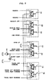
- the above-mentioned, directional control valves 3-6,8-12 comprise, for example, hydraulically-operated pilot valves, respectively, and are change-over controlled by the corresponding pilot control devices depicted in FIG. 2 .
- the above-mentioned travel-controlling, right directional control valve 3 is controlled by a right travel motor control device 18, the travel-controlling, left directional control valve 12 is controlled by a left travel motor control device 19, the bucket-controlling, directional control valve 4 is controlled by a bucket control motor 20, the boom-controlling, first directional control valve 5 and the boom-controlling, second directional control valve 10 are controlled by a boom control device 21, the arm-controlling, first directional control valve 9 and the arm-controlling, second directional control valve 10 are controlled by an arm control device 22, the revolving-controlling, directional control valve 8 is controlled by a revolving control device 23, and the reserve-actuator-controlling, directional control valve 11 is controlled by the reserve actuator control device 24.
- a communication line 13 communicating the most upstream side of the first control valve group 15a with a supply line 11a to the reserve-actuator-controlling, directional control valve 11 and a merge control valve 14 having an open position and a closed position for selectively maintaining the communication line 13 in or out of communication.
- an interlocked control means which can change over the merge control valve 14 to the open position and the bypass on/off valve 7 to the closed position, respectively, in association with the change-over operation of the reserve actuator control device 24 to change over the reserve-actuator-controlling, directional control valve 11.
- This interlocked control means includes a shuttle valve 26 and a pilot line 27 communicating the shuttle valve 26 with respective drive portions of the merge control valve 14 and bypass on/off valve 7.
- the shuttle valve 26 can detect a pilot pressure, which is outputted, for example, from the reserve actuator control device 24, via a control line 25a or control line 25b through which the pilot pressure is guided to change over the reserve-actuator-controlling, directional control valve 11, and can output as a pressure signal for changing over the merge control valve 14 to the open position and the bypass on/off valve 7 to the closed position, respectively.
- a selective change-over means for selectively changing over to one of a state in which the above-mentioned change-over operation of the merge control valve 14 to the open position by the interlocked control means is feasible and another state in which this change-over operation is infeasible.
- This selective change-over means comprises a selective control valve 28 and a selector switch 29.
- the selective control valve 28 is arranged in the pilot line 27, and serves to selectively change over to one of a first state, in which a pilot pressure outputted from the shuttle valve 26 can be supplied to the drive portion of the merge control valve 14, and a second state in which the pilot pressure cannot be supplied to the drive portion of the merge control valve 14.
- the selector switch 29 outputs an electrical signal to selectively operate the selective control valve 28 such that it is maintained in one of the above-mentioned first state and second state.
- This hydraulic drive system is also constructed such that the first control valve group 15a including the bypass on/off valve 7, the second control valve group 15b including the reserve-actuator-controlling, directional control valve 11, the communication line 13 and the merge control valve 14, all of which have been mentioned above, are arranged in a single housing 15.
- This first hydraulic drive system is operated as will be described hereinafter.
- the selective control valve 28 With the selector switch 29 not operated, for example, the selective control valve 28 is maintained in the closed position which is a lower changed-over position as viewed in FIG. 1 . During this time, the pilot line 27 is maintained out of communication. Described specifically, the connections between the shuttle valve 26 and the respective drive portions of the merge control valve 14 and bypass on/off valve 7 are cut off. It is, therefore, impossible to change over the merge control valve 14 to the open position, which is an upper changed-over position as viewed in FIG. 1 , by a pilot pressure outputted from the reserve actuator control device 24.
- the selective control valve 28 When the selector switch 29 is operated, the selective control valve 28 is changed over to the open position which is the upper changed-over position as viewed in FIG. 1 . At this time, the pilot line 27 is communicated. Described specifically, the shuttle valve 26 is brought into communication with the respective drive portions of the merge control valve 14 and bypass on/off valve 7. This makes it possible to change over the merge control valve 14 to the open position, which is the upper changed-over position as viewed in FIG. 1 , by a pilot pressure outputted from the reserve actuator control device 24.
- the reserve-actuator-controlling directional control valve 11 When the reserve actuator control device 24 is operated in this state with a view to operating the actuator controlled by the reserve-actuator-controlling directional control valve 11, the reserve-actuator-controlling directional control valve 11 is changed over from the neutral position by a pilot pressure outputted from the reserve actuator control device 24. Concurrently with this, the pilot pressure outputted from the reserve actuator control device 24 is applied to the drive portion of the merge control valve 14 and the drive portion of the bypass on/off valve 7 via the shuttle valve 26, the selective control valve 28 and the pilot line 27, so that the merge control valve 14 and the bypass on/off valve 7 are changed over to the open position and the closed position, respectively.
- the pressure oil from the first hydraulic pump 1 is guided to the supply line 11a to the reserve-actuator-controlling, directional control valve 11 via the merge control valve 14 and the communication line 13.
- the pressure oil from the first hydraulic pump 1 and the pressure oil from the second hydraulic pump 2 are both supplied to the reserve-actuator-controlling, directional control valve 11, and further to the actuator controlled by the reserve-actuator-controlling, directional control valve 11. Accordingly, the actuator controlled by the reserve-actuator-controlling, directional control valve 11 can be operated at a fast speed faster than the above-mentioned operating speed.
- a change-over operation of the selective control valve 28 by an operation of the selector switch 29 makes it possible to selectively change the maximum value of the operating speed of the actuator, which is controlled by the reserve-actuator-controlling, directional control valve 11, either to a slow speed available by the supply of only the pressure oil from the second hydraulic pump 2 or to a fast speed available by the merging of the pressure oil from the first hydraulic pump 1 with the pressure oil from the second hydraulic pump 2.
- the communication line 13 is not an external line so that it is not arranged surrounding the housing 15. Owing to these features, the length of the communication line 13 can be set extremely short.
- the communication line 13 is arranged within the housing 15, and a connection part at the most upstream side of the first control valve group 15a, to which connection part the communication line 13 is connected at an end thereof, and a connection part of the supply line 11a to the reserve-actuator-controlling, directional control valve 11, to which connection part the communication line 13 is connected at an opposite end thereof, are both located within the housing 15. It is, therefore, possible to prevent leakage of oil supplied to the communication line 13, in other words, leakage of oil from the housing 15.
- connection part at the most upstream side of the first control valve group 15, to which connection part the communication line 13 is connected at the one end thereof, and the connection part of the supply line 11a to the reserve-actuator-controlling, directional control valve 11, to which connection part the communication line 13 is connected at the opposite end thereof, can be both formed upon fabrication of the housing 15. No additional line connecting work is therefore needed for the communication line 13.
- the actuator which is controlled by the reserve-actuator-controlling, directional control valve 11 connected to the second hydraulic pump 2, the actuator for the boom cylinder or the like, which is controlled by the boom-controlling, first directional control valve connected to the first hydraulic pump 1, can be achieved while surely retaining their own independence.
- directional control valve 11 As the maximum value of the operating speed of the actuator controlled by the reserve-actuator-controlling, directional control valve 11 can be changed, the actuator can be controlled, for example, at two speeds consisting of a slow speed and a fast speed, and control to the fast speed makes it possible to improve the efficiency of work by an attachment or the like, said work being performed by the operation of the actuator.
- the successful prevention of leakage of oil supplied to the communication line 13 makes it possible to decrease occurrence of insufficiency in the amount of oil in the circuit and also to prevent contamination of surrounding equipment by such oil leakage.
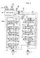
- FIGS. 3 and 4 are explanatory diagrams showing the hydraulic drive system according to the second hydraulic drive system not according to the present invention for the civil engineering or construction machine, in which FIG. 3 is the hydraulic circuit diagram showing the construction of the second hydraulic drive system and FIG. 4 is the diagram illustrating the shuttle block arranged in the second hydraulic drive system shown in FIG. 3 .
- the second hydraulic drive system depicted in FIGS. 3 and 4 is also provided with an interlocked control means which can change over the merge control valve 14 to the open position and the bypass on/off valve 7 to the closed position, respectively, in association with the change-over operation of the reserve actuator control device 24 to change over the reserve-actuator-controlling, directional control valve 11.
- This interlocked control means includes a first shuttle valve, that is, a shuttle valve 26 and a first pilot line connecting the shuttle valve 26 with the respective drive portions of the merge control valve 14 and bypass on/off valve 7.
- the first shuttle valve can detect a pilot pressure outputted from the reserve actuator control device 24 and can output as a pressure signal for changing over the merge control valve 14 to the open position and the bypass on/off valve 7 to the closed position, respectively.
- This selective change-over means includes a selective control valve 28, which is arranged in the above-mentioned first pilot line, that is, the pilot line 27 and selectively changes over to one of a first state, in which a pilot pressure outputted from the above-mentioned first shuttle valve, that is, the shuttle valve 26 can be supplied to the drive portion of the merge control valve 14, and a second state in which the pilot pressure cannot be supplied to the drive portion of the merge control valve 14.
- this second hydraulic drive system is provided with a merge control valve control means for performing control such that the merge control valve 14 is changed over to the closed position upon operation of a predetermined directional control valve included in the first control valve group 15a connected to the first hydraulic pump 1, for example, the bucket-controlling, directional control valve 4, the boom-controlling, first directional control valve 5 or the arm-controlling, second directional control valve 6.
- This merge control valve control means is constructed to include second shuttle valves 33, 34, 35,36,37,38 depicted in FIG. 4 and a second pilot line 31.
- the second shuttle valves 33,34,35,36,37,38 detect, for example, pilot pressures outputted from control devices for the corresponding directional control valves, such as the above-mentioned bucket control device 20, boom control device 21 and arm control device 22, and output them as control signals for controlling the merge control valve 14.
- the second pilot line 31 communicates these second shuttle valves 33-38 to the drive portion of the merge control valve 14, said drive portion serving to change over the merge control valve to the closed position, specifically to a drive portion forming a spring compartment.
- designated at numeral 32 in FIG. 4 is a shuttle valve for detecting a pilot pressure which is outputted upon operation of the right travel motor control device 18 or left travel motor control device 19. This shuttle valve 32 is arranged, for example, in communication with the second shuttle valve 38.
- the above-mentioned first shuttle valve namely, the shuttle valve 26, the second shuttle valves 33-38 and the shuttle valve 32 are accommodated within a shuttle block 30 formed of a single housing.
- the remaining construction is similar to the corresponding construction of the above-mentioned first hydraulic drive system shown in FIGS. 1 and 2 .
- This second hydraulic drive system is operated as will be described hereinafter.
- the selective control valve 28 With the selector switch 29 not operated, for example, the selective control valve 28 is maintained in the closed position which is a lower changed-over position as viewed in FIG. 1 . During this time, the pilot line 27 is maintained out of communication. Described specifically, the connections between the shuttle valve 26 and the respective drive portions of the merge control valve 14 and bypass on/off valve 7 are cut off. It is, therefore, impossible to change over the merge control valve 14 to the open position, which is an upper changed-over position as viewed in FIG. 1 , by a pilot pressure outputted from the reserve actuator control device 24.
- the selective control valve 28 When the selector switch 29 is operated, the selective control valve 28 is changed over to the open position which is the upper changed-over position as viewed in FIG. 1 . At this time, the pilot line 27 is communicated. Described specifically, the shuttle valve 26 is brought into communication with the respective drive portions of the merge control valve 14 and bypass on/off valve 7. This makes it possible to change over the merge control valve 14 to the open position, which is the upper changed-over position as viewed in FIG. 1 , by a pilot pressure outputted from the reserve actuator control device 24.
- the reserve-actuator-controlling directional control valve 11 is changed over from the neutral position by a pilot pressure outputted from the reserve actuator control device 24.
- the pilot pressure outputted from the reserve actuator control device 24 is applied to the drive portion of the merge control valve 14, specifically to a drive portion not forming the spring compartment and the drive portion of the bypass on/off valve 7 via the first shuttle valve, namely, the shuttle valve 26, the selective control valve 28 and the first pilot line, namely, the pilot line 27, so that the merge control valve 14 and the bypass on/off valve 7 are changed over to the open position and the closed position, respectively.
- the pressure oil from the first hydraulic pump 1 is guided to the supply line 11a to the reserve-actuator-controlling, directional control valve 11 via the merge control valve 14 and the communication line 13.
- the pressure oil from the first hydraulic pump 1 and the pressure oil from the second hydraulic pump 2 are both supplied to the reserve-actuator-controlling, directional control valve 11, and further to the actuator controlled by the reserve-actuator-controlling, directional control valve 11. Accordingly, the actuator controlled by the reserve-actuator-controlling, directional control valve 11 can be operated at a fast speed faster than the above-mentioned operating speed.
- the boom control device 21 When a control device for a predetermined directional control valve, for example, the boom control device 21 is operated, for example, in a state that the pressure oil from the first hydraulic pump 1 and the pressure oil from the second hydraulic pump 2 are both being supplied to the reserve-actuator-controlling, directional control valve 11, the boom-controlling, first directional control valve 5 belonging to the first control valve group 15a in which the reserve-actuator-controlling, directional control valve 11 is not included is changed over from the neutral position by a pilot pressure outputted from the boom control device 21. Concurrently with this, the pilot pressure outputted from the boom control device 21 is detected at the second shuttle valves 34,36,37,38, and is applied via the second pilot line 31 to the drive portion forming the spring compartment of the merge control valve 14.
- the merge control valve 14 is changed over from the open position to the closed position. Accordingly, the pressure oil from the first hydraulic pump 1 is blocked by the merge control valve 14 and is no longer supplied to the reserve-actuator-controlling, directional control valve 11. Namely, the pressure oil from the first hydraulic pump 1 is supplied to the boom-controlling, first directional control valve 5, and only the pressure oil from the second hydraulic pump 2 is supplied to the reserve-actuator-controlling, directional control valve 11.
- first directional control valve 5 when the boom-controlling, first directional control valve 5 is operated, the boom cylinder controlled by the boom-controlling, first directional control valve 5 can be operated by the pressure oil 1 from the first hydraulic pump and further, the maximum value of the operating speed of the actuator controlled by the reserve-actuator-controlling, directional control valve 11 is controlled to a slow speed which relies upon only the pressure oil from the second hydraulic pump 2.
- the second hydraulic drive system constructed as described above brings about similar advantageous effects as the above-mentioned first hydraulic drive system. Moreover, especially when a control device for a predetermined directional control valve such as the boom control device 21 is operated in the state that the pressure oil from the first hydraulic pump 1 and the pressure oil from the first hydraulic pump 2 are both being supplied to the reserve-actuator-controlling, directional control valve 11, the pressure oil from the first hydraulic pump 1 and the pressure oil from the second hydraulic pump 2 are supplied to predetermined directional control valve such as the boom-controlling, first directional control valve 5 and the reserve-actuator-controlling, directional control valve 11, respectively, without needing an operation of the selector switch 29, thereby permitting an automatic transfer to a combined operation of the actuator controlled by the predetermined directional control valve and the actuator controlled by the reserve-actuator-controlling, directional control valve 11. Excellent operability is thus obtained.
- a control device for a predetermined directional control valve such as the boom control device 21 is operated in the state that the pressure oil from the first hydraulic pump 1 and the
- the shuttle valve 26 as the first shuttle valve, the second shuttle valves 33-38 and the shuttle valve 32 are accommodated within the shuttle block 30 which forms a single housing.
- a group of shuttle valves can be arranged together, thereby realizing the construction of the whole system into a compact structure.
- first hydraulic drive system and second hydraulic drive system are each constructed such that the selective control switch 28 is changed over responsive to an operation of the selector switch 29 and also such that the merge control valve 14 and the bypass on/off valve 7 are changed over responsive to a pilot pressure produced by an operation of the reserve actuator control device 24 for the control of the reserve-actuator-controlling, directional control valve 11.
- the present invention is limited neither to the construction that the selector switch 29 is arranged as described above nor to the construction that the merge control valve 14 and the bypass on/off valve 7 are changed over responsive to the pilot pressure produced by the operation of the reserve actuator control device 24 for the control of the reserve-actuator-controlling, directional control valve 11.
- the present invention may be constructed, for example, such that the merge control valve 14 and the bypass on/off valve 7 are formed of hydraulically-operated pilot valves, respectively, as in the above-mentioned embodiments;
- the interlocked control means includes a predetermined hydraulic pressure source, such as a pilot pump, and a pilot line for guiding a pilot pressure, which has been outputted from the predetermined hydraulic pressure source, as a pressure signal for changing over the merge control valve 14 to the open position and at the same time, as a pressure signal for changing over the bypass on/off valve 7 to the closed position, without interposition of any shuttle valve;
- the selective change-over means is arranged in the part of a pilot line, through which the predetermined hydraulic pressure source and the drive portion of the merge control valve 14 are communicated with each other, and includes the selective control valve 28, which is composed of a solenoid valve for selectively changing over to one of a first state in which the above-mentioned pilot pressure outputted from the predetermined hydraulic source can be supplied to the drive portion
- an operation of the reserve actuator control device 24 with a view to operating the actuator controlled by the reserve-actuator controlling, directional control valve 11 changes over the reserve-actuator-controlling, directional control valve 11 from the neutral position, provided that the selective control valve 28 is set to inhibit a change-over operation of the merge control valve 14 to the open position by a pilot pressure, which is outputted from the predetermined hydraulic pressure source, when the operation detecting means detects an operation of the reserve actuator control device 24, for example.
- the merge control valve 14 is maintained in the closed position by the selective control valve 28 as mentioned above.
- the pressure oil from the first hydraulic pump 1 cannot be supplied to the supply line 11a to the reserve-actuator-controlling, directional control valve 11 via the merge control valve 14 and the communication line 13, and only the pressure oil from the second hydraulic pump 2 is supplied to the reserve-actuator-controlling, directional control valve 11. Namely, only the pressure oil from the second hydraulic pump 2 is supplied to the actuator controlled by the reserve-actuator-controlling, directional control valve 11, and the actuator can be operated at a relatively slow speed.
- An operation of the reserve actuator control device 24 with a view to operating the actuator controlled by the reserve-actuator-controlling, directional control valve 11 changes over the reserve-actuator-controlling, directional control valve 11 from the neutral position, provided that the selective control valve 28 is set to permit a change-over operation of the merge control valve 11 to the open position by a pilot pressure, which is outputted from the predetermined hydraulic pressure source, when the operation detecting means detects an operation of the reserve actuator control device 24, for example.
- the operation of the reserve actuator control device 24 is detected by the operation detection means, the pilot pressure outputted from the predetermined hydraulic pressure source is applied to the drive portion of the merge control valve 14 and the drive portion of the bypass on/off valve 7 via the selective control valve 28 and the pilot line 27, so that the merge control valve 14 and the bypass on/off valve 7 are changed over to the open position and the closed position, respectively.
- the pressure oil from the first hydraulic pump 1 is guided to the supply line 11a to the reserve-actuator-controlling, directional control valve 11 via the merge control valve 14 and the communication line 13.
- the pressure oil from the first hydraulic pump 1 and the pressure oil from the second hydraulic pump 2 are both supplied to the reserve-actuator-controlling, directional control valve 11, and further to the actuator controlled by the reserve-actuator-controlling, directional control valve 11. Accordingly, the actuator controlled by the reserve-actuator-controlling, directional control valve 11 can be operated at a fast speed faster than the above-mentioned operating speed.
- the hydraulic drive system constructed as described above it is also possible to selectively change the maximum value of the operating speed of the actuator, which is controlled by the reserve-actuator-controlling, directional control valve 11, either to a slow speed available by the supply of only the pressure oil from the second hydraulic pump 2 or to a fast speed available by the merging of the pressure oil from the first hydraulic pump 1 with the pressure oil from the second hydraulic pump 2.
- the second hydraulic drive system can, therefore, bring about similar effects as the above-mentioned first hydraulic drive system.
- FIGS. 5 , 6 and 7 are diagrams for explaining the hydraulic drive system according to an embodiment of the present invention for the civil engineering or construction machine, in which FIG. 5 is the hydraulic circuit diagram showing the construction of the embodiment of the present invention, FIG. 6 is the diagram illustrating the pilot control device arranged in the embodiment shown in FIG. 5 , and FIG. 7 is a diagram depicting the construction of the controller arranged in the embodiment shown in FIG. 5 .
- this embodiment corresponds to the first, second and third aspects described above.
- a branch line 27a is arranged on the pilot line 27 connected to the shuttle valve 26 which constitutes the interlocked control means for permitting changing over the merge control valve 14 and the bypass on/off valve 7 to the open position and the closed position, respectively.
- a selective control valve 28a Arranged in this branch line 27a is a selective control valve 28a, which constitutes a selective change-over means for selectively changing over to one of a state, in which the above-mentioned change-over operation of the merge control valve 14 to the open position by the interlocked control means is feasible, and another state, in which the change-over operation is infeasible, and is composed of a solenoid valve, for example.
- the embodiment is provided with a valve opening area control means for controlling drive of the merge control valve 14 such that the valve opening area of the merge control valve 14 is changed to a predetermined valve opening area smaller than the valve opening area in its fully open position when, concurrently with a change-over operation of the reserve-actuator-controlling, directional control valve 11 by the reserve actuator control device 24, an actuator, which is included in the first control valve group 15a communicated to the first hydraulic pump 1 and may be applied with a load pressure higher than a load pressure to the actuator controlled by the reserve-actuator-controlling, directional control valve 11, for example, the boom-controlling, first directional control valve 5 for controlling drive of the unillustrated boom cylinder is operated, the arm-controlling, second directional control valve 6 for controlling drive of the unillustrated arm cylinder is operated or the travel-controlling, right directional control valve 3 for controlling drive of the unillustrated right drive motor is operated.
- an actuator which is included in the first control valve group 15a communicated to the first hydraulic pump 1 and may be applied
- This valve opening area control means includes a specific operation detecting means for detecting, for example, an operation of the boom-controlling, first directional control valve 5, the arm-controlling, second directional control valve 6 or the travel-controlling, right directional control valve 3 and outputting an electrical signal, and a controller 40 for performing a predetermined computation based on the above-mentioned electrical signal outputted from the specific operation detecting means and outputting a control signal, which is commensurate with results of the computation, as a signal for driving the selective control valve 28a.
- a specific operation detecting means for detecting, for example, an operation of the boom-controlling, first directional control valve 5, the arm-controlling, second directional control valve 6 or the travel-controlling, right directional control valve 3 and outputting an electrical signal
- a controller 40 for performing a predetermined computation based on the above-mentioned electrical signal outputted from the specific operation detecting means and outputting a control signal, which is commensurate with results of the computation, as a signal
- the above-mentioned specific operation detecting means includes a first pressure sensor 50 for detecting a pilot pressure, for example, upon operation of the arm control device 22 to have the unillustrated arm cylinder extended, namely, an arm-dumping pilot pressure Pa and outputting as an electrical signal to the controller 40, a second pressure sensor 51 for detecting a pilot pressure upon operation of the boom control device 21 to have the unillustrated boom cylinder extended, namely, a boom-raising pilot pressure Pb and outputting it as an electrical signal to the controller 40, and a third pressure sensor 52 for detecting a pilot pressure upon operation of the right travel motor control device 18 to have the unillustrated right travel motor driven, namely, a right travel pilot pressure Pt and outputting it as an electrical signal to the controller 40.
- a first pressure sensor 50 for detecting a pilot pressure, for example, upon operation of the arm control device 22 to have the unillustrated arm cylinder extended, namely, an arm-dumping pilot pressure Pa and outputting as an electrical signal to the controller 40
- the above-mentioned controller 40 includes, as shown in FIG. 7 , an arm-dumping function generator unit 41, a boom-raising function generator unit 42, a right-travel-motor-driving function generator unit 43, a minimum target value selector unit 44, and a control signal generator unit 45.
- the arm-dumping function generator unit 41 generates a target value Aa, which gradually becomes smaller as the value of the electrical signal outputted from the first pressure sensor 50, namely, the arm-dumping pilot pressure Pa increases.
- the boom-raising function generator unit 42 generates a target value Ab, which gradually becomes smaller as the value of the electrical signal outputted from the second pressure sensor 51, namely, the boom-raising pilot pressure Pb increases.
- the right-travel-motor-driving function generator unit 43 generates a target value At, which gradually becomes smaller as the value of the electrical signal outputted from the third pressure sensor 52, namely, the right travel pilot pressure Pt increases.
- the minimum target value selector unit 44 selects the smallest value of the target values Aa, Ab, At outputted from these function generator units 41, 42, 43 and outputs it as a minimum target value Am.
- the control signal generator unit 45 generates an input current i which gradually becomes larger as the minimum target value Am outputted from the minimum target value selector unit 44 decreases, that is, a control signal for controlling drive of the selective control valve 28a.
- the remaining fundamental construction is similar to the corresponding construction in the above-mentioned first hydraulic drive system shown in FIG. 1 .
- the selective control valve 28a is maintained in an open position, which is a lower changed-over position as viewed in FIG. 1 , when the input current i, namely, the control signal is not applied to the drive portion of the selective control valve 28a.
- the branch line 27a of the pilot line 27 is communicated.
- the shuttle valve 26 is connected to the drive portion of the merge control valve 14. This makes it possible to change over the merge control valve 14 to the open position, which is the upper changed-over position as viewed in FIG. 1 , by a pilot pressure outputted from the reserve actuator control device 24.
- the bypass on/off valve 7 is changed over to the closed position. Accordingly, the pressure oil from the first hydraulic pump 1 is guided to the supply line 11a to the reserve-actuator-controlling, directional control valve 11 via the merge control valve 14 and the communication line 13. Described specifically, the pressure oil from the first hydraulic pump 1 and the pressure oil from the second hydraulic pump 2 are both supplied to the reserve-actuator-controlling, directional control valve 11, and further to the actuator controlled by the reserve-actuator-controlling, directional control valve 11. Accordingly, the actuator controlled by the reserve-actuator-controlling, directional control valve 11 can be operated at a fast speed by the pressure oil from the two hydraulic pumps 1, 2.
- the value of the detected arm-dumping pilot pressure Pa, boom-dumping pilot pressure Pb or right travel pilot pressure Pt becomes large.
- the value of the corresponding one of the target values Aa, Ab, At becomes smaller.
- the target value Aa, Ab or Ac of the small value is inputted to the minimum target value selector unit 44, where the small value is selected as a minimum target value Am.
- This minimum target value Am is inputted to the control signal generator unit 45.
- this minimum target value Am is relatively small so that the input current i takes a large value.
- the input current i of the large value is fed as control signal from the controller 40 to the drive portion of the selective control valve 28a.
- the selective control valve 28a is changed over in accordance with the value of the control signal, namely, the input signal i toward the upper changed-over position as viewed in FIG. 5 , in other words, toward the closed position, and the branch line 27a is brought into a constricted state with a reduced opening area.
- An output pressure Pr guided through the shuttle valve 26, the pilot line 27 and the branch line 27a and outputted from the selective control valve 28a takes a relatively small value and therefore, drives the merge control valve 14 such that its valve opening area is reduced.
- FIG. 8 illustrates a relationship between the input current i fed from the above-mentioned controller 40 to the drive portion of the selective control valve 28a and the output Pr outputted from the selective control valve 28a. They are correlated such that the output pressure Pr becomes lower as the value of the input current i becomes greater.
- FIG. 9 illustrates a relationship between the above-mentioned output pressure Pr and the valve opening area Ar of the merge control valve 14. They are correlated such that the valve opening area Ar becomes smaller as the output pressure Pr becomes lower.
- the pressure oil from the first hydraulic pump 1 is restricted at the merge control valve 14 in this state, the amount of the pressure oil to be supplied from the first hydraulic pump to the reserve-actuator-controlling, directional control valve 11 via the communication line 13 and the supply line 11a is changed to a smaller amount.
- a substantial portion of the pressure oil from the first hydraulic pump 1 can, therefore, be supplied to the desired one of the arm-controlling, second directional control valve 6, the boom-controlling, first directional control valve 5 and the travel-controlling, right directional control valve 3.
- the actuator controlled by the specific directional control valve consisting of the arm-controlling, second directional control valve 6, the boom-controlling, first directional control valve 5 or the travel-controlling, right directional control valve 3, namely, the actuator to which a load pressure higher than that applied to the actuator controlled by the reserve-actuator-controlling directional control valve 11 can be driven together with the actuator controlled by the reserve-actuator-controlling directional control valve 11, thereby making it possible to achieve a good combined operation of these actuators and hence to improve the efficiency of the relevant work.
- the pressure oil supplied to the reserve-actuator-controlling directional control valve 11 during the combined operation of the actuator controlled by the specific directional control valve and the actuator controlled by the reserve-actuator-controlling directional control valve 11 is primarily the pressure oil delivered from the second hydraulic pump 2.
- the operating speed of the actuator controlled by the reserve-actuator-controlling directional control valve 11 is relatively slow.
- both of the pressure oil from the first hydraulic pump 1 and the pressure oil from the second hydraulic pump 2 can be supplied to the reserve-actuator-controlling directional control valve 11.
- the actuator controlled by the reserve-actuator-controlling directional control valve 11 can be operated at a fast speed.
- the embodiment also makes it possible to change the maximum value of the operating speed of the actuator controlled by the reserve-actuator-controlling directional control valve 11 and, especially when the actuator controlled by the reserve-actuator-controlling directional control valve 11 is singly operated, to efficiently perform the intended work via the actuator.
- the present invention can change the maximum value of the operating speed of the actuator controlled by the reserve-actuator-controlling, directional control valve and hence, can control the actuator at two speeds consisting of a slow speed and a fast speed.
- the efficiency of work by an attachment or the like, said work being performed by the operation of the actuator can be improved.
- the length of the communication line through which the first hydraulic pump and the reserve-actuator-controlling, directional control valve are connected with each other can be shortened, a pressure loss through the communication line can be reduced, and the actuator controlled by the reserve-actuator-controlling, directional control valve can be controlled with high accuracy.
- leakage of oil supplied to the communication line 13 can be prevented. This makes it possible to decrease occurrence of insufficiency in the amount of oil in the circuit and also to prevent contamination of surrounding equipment by such oil leakage. Moreover, line connecting work for the communication line can be obviated. This makes it possible to reduce the irksomeness of assembly work of the hydraulic drive system and hence to improve the efficiency of the assembly work.
- the merge control valve control means is operated, the pressure oil from the first hydraulic pump and the pressure oil from the second hydraulic pump are supplied to the predetermined directional control valve and the reserve-actuator-controlling, directional control valve, thereby permitting an automatic transfer to a combined operation of the actuator controlled by the predetermined directional control valve and the actuator controlled by the reserve-actuator-controlling, directional control valve. Excellent operability is thus obtained.
- the first shuttle valve and the second shuttle valve are accommodated within the shuttle block which forms a single housing.
- a group of shuttle valves can be arranged together, thereby making it possible to realize the construction of the whole system into a compact structure.
- the present invention it is also possible to change the maximum value of the operating speed of the actuator controlled by the reserve-actuator-controlling directional control valve. This makes it possible to drive the actuator at a relatively fast speed. When the actuator is driven at such a fast speed, the efficiency of work by an attachment or the like to be performed by operating the actuator can be improved. It is also possible to achieve a good combined operation of the actuator controlled by the reserve-actuator-controlling, directional control valve and the actuator controlled by a specific directional control valve belonging to the control valve group, in which the reserve-actuator-controlling, directional control valve is not included, and possibly applied with a load pressure higher than that applied to the actuator controlled by the reserve-actuator-controlling, directional control valve. Work intended to be performed by operating these actuators can, therefore, be performed with good efficiency.
Landscapes
- Engineering & Computer Science (AREA)
- Mining & Mineral Resources (AREA)
- Civil Engineering (AREA)
- General Engineering & Computer Science (AREA)
- Structural Engineering (AREA)
- Physics & Mathematics (AREA)
- Fluid Mechanics (AREA)
- Fluid-Pressure Circuits (AREA)
- Operation Control Of Excavators (AREA)
Description
- This invention relates to a hydraulic drive system for a civil engineering or construction machine such as a hydraulic excavator, which is suitable for arrangement in the civil engineering or construction machine and has a first control valve group connected to a first hydraulic pump and including plural directional control valves and a second control valve group connected to a second hydraulic pump and including plural directional control valves.
- As conventional art of this type, there is, for example, one disclosed in
JP 2642972 B2 - Connected to the first hydraulic pump is a first control valve group, which is provided on a most downstream side with a bypass on/off valve having an open position and a closed position for selectively maintaining a bypass passage in or out of communication and makes up a single housing including a revolving-controlling directional control valve, an arm-controlling directional control valve, and a travel-controlling directional control valve for one of traveling motors. The individual directional control valves in this first control valve group are connected parallel to the first hydraulic pump.
- Connected to the second hydraulic pump is a second control valve group, which makes up another housing including, in addition to a reserve directional control valve as an attachment-controlling directional control valve for controlling an attachment actuator for driving an attachment such as a hydraulic breaker or a hydraulic venchure, a boom-controlling directional control valve, a bucket-controlling directional control valve, and a travel-controlling directional control valve for the other traveling motor. The individual directional control valves in this second control valve group, except for the reserve directional control valve, are connected parallel to the second hydraulic pump.
- Further, a communication line is arranged to communicate a delivery line from the first hydraulic pump and a supply line to the reserve directional control valve with each other.
- This communication line is connected at one end thereof to the housing of the first control valve group and at an opposite end thereof to the housing of the second control valve group. In other words, the communication line is arranged as an external piping outside the respective housings.
- In addition, a shuttle valve is also arranged. The shuttle valve detects a pilot pressure which serves to change over the reserve directional control valve, and the shuttle valve takes it out as a control pressure for changing over the above-mentioned bypass on/off valve to the closed position.
- When the reserve directional control valve is changed over in the conventional art constructed as described above, its operating pressure is applied as a control pressure to a drive portion of the bypass on/off valve in the first control valve group via the shuttle valve, and the bypass on/off valve is changed over to the closed position. Pressure oil from the first hydraulic pump is, therefore, supplied to the communication line arranged outside the two housings. This pressure oil is supplied further to the reserve directional control valve, and then to the attachment actuator controlled by the reserve directional control valve. Accordingly, the attachment actuator controlled by the reserve directional control valve is driven by the pressure oil from the first hydraulic pump rather than pressure oil from the second hydraulic pump connected to the second control valve group to which the reserve directional control valve belongs.
- In the above-mentioned conventional art, the communication line through which the pressure oil from the first hydraulic pump is guided to the reserve directional control valve is a line arranged outside the housings in which the first control valve group and the second control valve group are accommodated, respectively, in other words, is an external line. The communication line, therefore, tends to become longer, leading to problems that a pressure loss tends to become large and the accuracy of control of attachment actuators tends to drop. Further, the above-mentioned communication line is connected at the one end thereof to the housing in which the first control valve group is accommodated and at the opposite end thereof to the housing in which the second control valve group is accommodated. Oil leakage, therefore, tends to occur at both of the connected parts. Occurrence of such oil leakage leads to insufficiency in the amount of oil in the circuit and also to contamination of surrounding equipment with the oil.
- Additional work is required to connect the one end of the communication line to the housing in which the first control valve group is accommodated and also to connect the opposite end of the communication line to the housing in which the second control valve group is accommodated. Accordingly, assembly work of the hydraulic circuit, that is, the hydraulic drive system becomes irksome, thereby leading to a reduction in the efficiency of the assembly work.
- In the above-mentioned conventional art, it is only the pressure oil delivered from the first hydraulic pump that is supplied to the reserve directional control valve. The operating speed of the attachment actuator controlled by the reserve directional control valve is, therefore, limited in a wholesale manner to a slow speed (the first speed). It is, therefore, impossible to change the maximum value of the operating speed of the attachment actuator, for example, to set the operating speed of the attachment actuator at two speeds consisting of a slow speed and a fast speed. This has led to a problem that no improvement can be expected in the efficiency of work to be performed by the operation of the attachment actuator.
- The present invention has been completed in view of the above-described circumstances of the conventional art, and an object of the present invention is to provide a hydraulic drive system for civil engineering or construction machine, which can change the maximum value of the operating speed of an actuator controlled by a reserve directional control valve and can also achieve good combined operation of the actuator, which is controlled by the reserve directional control valve, and an actuator which is controlled by a specific directional control valve belonging to a control valve group without the reserve directional control valve and may be applied with a load pressure higher than a load pressure to the actuator controlled by the reserve directional control valve.
- To achieve the object, on the other hand, the present invention also provides in an first aspect thereof a hydraulic drive system for a civil engineering or construction machine, said system being provided with a first hydraulic pump and a second hydraulic pump, a first control valve group connected to the first hydraulic pump, provided on a most downstream side thereof with a bypass on/off valve having an open position and a closed position for selectively maintaining a bypass passage in or out of communication, and a second control valve group connected to the second hydraulic pump and comprised of plural directional control valves including a reserve directional control valve, characterized in that the system is provided with a communication line communicating a most upstream side of the first control valve group with a supply line to the reserve directional control valve, a merge control valve having an open position and a closed position to selectively maintain the communication line in or out of communication, an interlocked control means for permitting an operation to change over the merge control valve to the open position and the bypass on/off valve to the closed position in association with a change-over operation of a reserve control device for changing over the reserve directional control valve, a selective change-over means capable of selectively taking one of a state, in which the operation to change over the merge control valve to the open position by the interlocked control means is feasible, and another state in which the operation to change over the merge control valve to the open position by the interlocked control means is infeasible, and a valve opening area control means for controlling drive of the merge control valve such that, when a specific directional control valve included in the first control valve group for controlling drive of an actuator to which a load pressure higher than a load pressure to an actuator controlled by the reserve directional control valve may be applied is operated concurrently with a change-over operation of the reserve directional control valve by the reserve control device, a valve opening area of the merge control valve is changed to a predetermined small valve opening area and said interlocked control means acts to hold said bypass on/off valve at said closed position in response to a change-over operation of said reserve control device even when said specific directional control valve is operated and said opening area of said merge control valve is made smaller by said valve opening area control means.
- In the first aspect constructed as described above, the reserve directional control valve is changed over from a neutral position when the reserve control device is operated to operate the actuator controlled by the reserve directional control valve, for example, in a state that the selective change-over moans has boon operated to permit a change-over operation of the merge control valve to the open position by the interlocked control means. Concurrently with this, the interlocked control means is operated to change over the merge control valve and the bypass on/off valve to the open position and the closed position, respectively. Accordingly, the pressure oil from the first hydraulic pump is guided to the supply line to the reserve directional control valve via the merge control valve and the communication line. Namely, the pressure oil from the first hydraulic pump and the pressure oil from the second hydraulic pump are both supplied to the reserve directional control valve and further to the actuator controlled by the reserve directional control valve. The actuator controlled by the reserve directional control valve can be operated at a fast speed accordingly.
- When, as mentioned above, the specific directional control valve included in the first control valve group is operated and changed over either after the reserve control device has been operated and the reserve directional control valve has been changed over from the neutral position or concurrently with a change-over operation of the reserve directional control valve from the neutral position in a state that the selective change-over means has been operated to permit a change-over operation of the merge control valve to the open position by the interlocked control means, the valve opening area control means operates such that the valve opening area of the merge control valve is controlled to the predetermined small valve open area.
- As a result, the merge control valve is controlled such that the supply of the pressure oil from the first hydraulic pump to the reserve directional control valve via the merge control valve is reduced, and therefore, a sufficient portion of the pressure oil from the first hydraulic pump can be supplied to the specific directional control valve. Accordingly, the actuator controlled by the specific directional control valve, in other words, the actuator to which a load pressure higher than that to be applied to the actuator controlled by the reserve directional control valve may be applied can be driven together with the actuator controlled by the reserve directional control valve, thereby making it possible to achieve a good combined operation of these actuators.
- To achieve the object, the present invention also provides in a second aspect thereof a hydraulic drive system as described above in connection with the first aspect, wherein the reserve directional control valve comprises a hydraulically-operated pilot valve, the reserve control device comprises a pilot-operated control device for outputting a pilot pressure to change over the reserve directional control valve, and the merge control valve and the bypass on/off valve comprise hydraulically-operated pilot valves, respectively, the interlocked control means includes a shuttle valve, which can detect a pilot pressure outputted from the reserve control device and can output the pilot pressure as a pressure signal for changing over the merge control valve to the open position and the bypass on/off valve to the closed position, and a pilot line communicating the shuttle valve with respective drive portions of the merge control valve and the bypass on/off valve, and the selective change-over means includes a selective control valve arranged in a part of the pilot line, which communicates the shuttle valve with the drive portion of the merge control valve, and capable of selectively taking one of a first state in which a pilot pressure outputted from the shuttle valve can be supplied to the drive portion of the merge control valve and a second state in which a pilot pressure outputted from the shuttle valve cannot be supplied to the drive portion of the merge control valve.
- To achieve the object, the present invention also provides in a third aspect thereof a hydraulic drive system as described above in connection with the second aspect, wherein the selective control valve comprises a solenoid valve; and the valve opening area control means includes a specific operation detecting means for detecting an operation of the specific directional control valve, which is included in the first control valve group, and outputting an electrical signal, and a controller for performing a predetermined computation based on the electrical signal outputted from the specific operation detecting means and outputting a control signal, which is commensurate with results of the computation, as a signal for driving the selective control valve.
- In the third aspect constructed as described above, when an operation of the specific directional control valve included in the first control valve group is detected by the specific operation detecting means, an electrical signal is outputted to the controller from the specific operation detecting means. The controller outputs a control signal, which is commensurate with the electrical signal, to the drive portion of the selective control valve, and accordingly, the shuttle valve is restricted such that a pilot pressure to be supplied from the shuttle valve to the drive portion of the merge control valve becomes lower. As a consequence, the merge control valve is controlled such that its valve opening area is reduced to a predetermined small valve opening area.
-
-
FIG. 1 is a hydraulic circuit diagram showing the construction of a first hydraulic drive system not according to the present invention for a civil engineering or construction machine; -
FIG. 2 is a diagram illustrating a pilot control device arranged in the first hydraulic drive system shown inFIG. 1 ; -
FIG. 3 is a hydraulic circuit diagram showing the construction of a second hydraulic drive system not according to the present invention; -
FIG. 4 is a diagram illustrating a shuttle block arranged in the second hydraulic drive system shown inFIG. 3 ; -
FIG. 5 is a hydraulic circuit diagram showing the construction of an embodiment of a hydraulic drive system according to the present invention; -
FIG. 6 is a diagram illustrating a pilot control device arranged in the embodiment shown inFIG. 5 ; -
FIG. 7 is a diagram illustrating a controller arranged in the embodiment shown inFIG. 5 ; -
FIG. 8 is a diagram illustrating output pressure characteristics of a selective control valve arranged in the embodiment shown inFIG. 5 ; and -
FIG. 9 is a diagram illustrating characteristics on a valve opening area of a merge control valve arranged in the embodiment shown inFIG. 5 . - An embodiment of the hydraulic drive system according to the present invention for the civil engineering or construction machine will hereinafter be described based on the drawings.
-
FIGS. 1 and2 are explanatory diagrams showing the first hydraulic drive system not according to the present invention for the civil engineering or construction machine, in whichFIG. 1 is the hydraulic circuit diagram showing the construction of the first hydraulic drive system andFIG. 2 is the diagram illustrating the pilot control device arranged in the first hydraulic drive system shown inFIG. 1 . - The first hydraulic drive system depicted in
FIGS. 1 and2 is suited for arrangement, for example, in a hydraulic excavator, and is provided with a firsthydraulic pump 1, a secondhydraulic pump 2, a firstcontrol valve group 15a connected to the firsthydraulic pump 1, and a secondcontrol valve group 15b connected to the secondhydraulic pump 2. - The first
control valve group 15a includes, on a most downstream side thereof, a bypass on/offvalve 7 having an open position and a closed position for selectively maintaining a bypass line either in or out of communication, and also includes plural directional control valves such as a bucket-controlling,directional control valve 4 for controlling drive of a bucket cylinder, a boom-controlling, firstdirectional control valve 5 for controlling drive of a boom cylinder and a arm-controlling, seconddirectional control valve 6 for controlling drive of an arm cylinder, in addition to a travel-controlling, rightdirectional control valve 3 arranged on a most upstream side for controlling one of travel motors. - The second
control valve group 15b includes, in addition to a revolving-controlling,directional control valve 8 arranged on a most upstream side thereof for controlling drive of a revolving motor, an arm-controlling, firstdirectional control valve 9 for controlling drive of the above-mentioned arm cylinder, a boom-controlling, seconddirectional control valve 10 for controlling drive of the above-mentioned boom cylinder, the reserve-actuator-controlling,directional control valve 11 for controlling drive of an attachment actuator, and a travel-controlling, leftdirectional control valve 12 for controlling drive of the other traveling motor. - The above-mentioned, directional control valves 3-6,8-12 comprise, for example, hydraulically-operated pilot valves, respectively, and are change-over controlled by the corresponding pilot control devices depicted in
FIG. 2 . Described specifically, the above-mentioned travel-controlling, rightdirectional control valve 3 is controlled by a right travelmotor control device 18, the travel-controlling, leftdirectional control valve 12 is controlled by a left travelmotor control device 19, the bucket-controlling,directional control valve 4 is controlled by abucket control motor 20, the boom-controlling, firstdirectional control valve 5 and the boom-controlling, seconddirectional control valve 10 are controlled by aboom control device 21, the arm-controlling, firstdirectional control valve 9 and the arm-controlling, seconddirectional control valve 10 are controlled by anarm control device 22, the revolving-controlling,directional control valve 8 is controlled by a revolvingcontrol device 23, and the reserve-actuator-controlling,directional control valve 11 is controlled by the reserveactuator control device 24. Each of these pilot control devices outputs an output pressure of apilot pump 16, said output pressure being specified by a pilot pressure relief valve 17 in accordance with its stroke, as a pilot pressure for changing over the corresponding directional control valve. - Also arranged is a
communication line 13 communicating the most upstream side of the firstcontrol valve group 15a with asupply line 11a to the reserve-actuator-controlling,directional control valve 11 and amerge control valve 14 having an open position and a closed position for selectively maintaining thecommunication line 13 in or out of communication. Arranged further is an interlocked control means which can change over themerge control valve 14 to the open position and the bypass on/offvalve 7 to the closed position, respectively, in association with the change-over operation of the reserveactuator control device 24 to change over the reserve-actuator-controlling,directional control valve 11. This interlocked control means includes ashuttle valve 26 and apilot line 27 communicating theshuttle valve 26 with respective drive portions of themerge control valve 14 and bypass on/offvalve 7. Theshuttle valve 26 can detect a pilot pressure, which is outputted, for example, from the reserveactuator control device 24, via acontrol line 25a orcontrol line 25b through which the pilot pressure is guided to change over the reserve-actuator-controlling,directional control valve 11, and can output as a pressure signal for changing over themerge control valve 14 to the open position and the bypass on/offvalve 7 to the closed position, respectively. - Arranged still further is a selective change-over means for selectively changing over to one of a state in which the above-mentioned change-over operation of the
merge control valve 14 to the open position by the interlocked control means is feasible and another state in which this change-over operation is infeasible. This selective change-over means comprises aselective control valve 28 and aselector switch 29. Theselective control valve 28 is arranged in thepilot line 27, and serves to selectively change over to one of a first state, in which a pilot pressure outputted from theshuttle valve 26 can be supplied to the drive portion of themerge control valve 14, and a second state in which the pilot pressure cannot be supplied to the drive portion of themerge control valve 14. Theselector switch 29 outputs an electrical signal to selectively operate theselective control valve 28 such that it is maintained in one of the above-mentioned first state and second state. - This hydraulic drive system is also constructed such that the first
control valve group 15a including the bypass on/offvalve 7, the secondcontrol valve group 15b including the reserve-actuator-controlling,directional control valve 11, thecommunication line 13 and themerge control valve 14, all of which have been mentioned above, are arranged in asingle housing 15. This first hydraulic drive system is operated as will be described hereinafter. - With the
selector switch 29 not operated, for example, theselective control valve 28 is maintained in the closed position which is a lower changed-over position as viewed inFIG. 1 . During this time, thepilot line 27 is maintained out of communication. Described specifically, the connections between theshuttle valve 26 and the respective drive portions of themerge control valve 14 and bypass on/offvalve 7 are cut off. It is, therefore, impossible to change over themerge control valve 14 to the open position, which is an upper changed-over position as viewed inFIG. 1 , by a pilot pressure outputted from the reserveactuator control device 24. When the reserveactuator control device 24 is operated in this state to operate the actuator controlled by the reserve-actuator controlling,directional control valve 11, a pilot pressure outputted from the reserveactuator control device 24 is guided to thecontrol line directional control valve 11 is changed over from a neutral position. At this time, themerge control valve 14 is maintained in the closed position by theselective control valve 28 as mentioned above. Therefore, pressure oil from the firsthydraulic pump 1 cannot be supplied to thesupply line 11a to the reserve-actuator-controlling,directional control valve 11 via themerge control valve 14 and thecommunication line 13, and only pressure oil from the secondhydraulic pump 2 is supplied to the reserve-actuator-controlling,directional control valve 11. Namely, only the pressure oil from the secondhydraulic pump 2 is supplied to the actuator controlled by the reserve-actuator-controlling,directional control valve 11, and the actuator can be operated at a relatively slow speed. When a directional control valve belonging to the firstcontrol valve group 15a connected to the firsthydraulic pump 1, for example, the boom-controlling, firstdirectional control valve 5 is changed over in this state, the pressure oil from the firsthydraulic pump 1 is supplied to the boom cylinder via the boom-controlling, firstdirectional control valve 5, thereby making it possible to perform a combined operation of this boom cylinder and the actuator controlled by the reserve-actuator-controlling,directional control valve 11. - When the
selector switch 29 is operated, theselective control valve 28 is changed over to the open position which is the upper changed-over position as viewed inFIG. 1 . At this time, thepilot line 27 is communicated. Described specifically, theshuttle valve 26 is brought into communication with the respective drive portions of themerge control valve 14 and bypass on/offvalve 7. This makes it possible to change over themerge control valve 14 to the open position, which is the upper changed-over position as viewed inFIG. 1 , by a pilot pressure outputted from the reserveactuator control device 24. - When the reserve
actuator control device 24 is operated in this state with a view to operating the actuator controlled by the reserve-actuator-controllingdirectional control valve 11, the reserve-actuator-controllingdirectional control valve 11 is changed over from the neutral position by a pilot pressure outputted from the reserveactuator control device 24. Concurrently with this, the pilot pressure outputted from the reserveactuator control device 24 is applied to the drive portion of themerge control valve 14 and the drive portion of the bypass on/offvalve 7 via theshuttle valve 26, theselective control valve 28 and thepilot line 27, so that themerge control valve 14 and the bypass on/offvalve 7 are changed over to the open position and the closed position, respectively. As a result, the pressure oil from the firsthydraulic pump 1 is guided to thesupply line 11a to the reserve-actuator-controlling,directional control valve 11 via themerge control valve 14 and thecommunication line 13. Described specifically, the pressure oil from the firsthydraulic pump 1 and the pressure oil from the secondhydraulic pump 2 are both supplied to the reserve-actuator-controlling,directional control valve 11, and further to the actuator controlled by the reserve-actuator-controlling,directional control valve 11. Accordingly, the actuator controlled by the reserve-actuator-controlling,directional control valve 11 can be operated at a fast speed faster than the above-mentioned operating speed. - As has been described above, a change-over operation of the
selective control valve 28 by an operation of theselector switch 29 makes it possible to selectively change the maximum value of the operating speed of the actuator, which is controlled by the reserve-actuator-controlling,directional control valve 11, either to a slow speed available by the supply of only the pressure oil from the secondhydraulic pump 2 or to a fast speed available by the merging of the pressure oil from the firsthydraulic pump 1 with the pressure oil from the secondhydraulic pump 2. - The
communication line 13, through which the most upstream side of the firstcontrol valve group 15a and thesupply line 11a to the reserve-actuator-controlling,directional control valve 11 are communicated with each other, and themerge control valve 14 are arranged together with the firstcontrol valve group 15a, which does not include the reserve-actuator-controlling,directional control valve 11, and the secondcontrol valve group 15b, which includes the reserve-actuator-controlling,directional control valve 11, in thesingle housing 15. In particular, thecommunication line 13 is not an external line so that it is not arranged surrounding thehousing 15. Owing to these features, the length of thecommunication line 13 can be set extremely short. - Further, the
communication line 13 is arranged within thehousing 15, and a connection part at the most upstream side of the firstcontrol valve group 15a, to which connection part thecommunication line 13 is connected at an end thereof, and a connection part of thesupply line 11a to the reserve-actuator-controlling,directional control valve 11, to which connection part thecommunication line 13 is connected at an opposite end thereof, are both located within thehousing 15. It is, therefore, possible to prevent leakage of oil supplied to thecommunication line 13, in other words, leakage of oil from thehousing 15. - Moreover, the connection part at the most upstream side of the first
control valve group 15, to which connection part thecommunication line 13 is connected at the one end thereof, and the connection part of thesupply line 11a to the reserve-actuator-controlling,directional control valve 11, to which connection part thecommunication line 13 is connected at the opposite end thereof, can be both formed upon fabrication of thehousing 15. No additional line connecting work is therefore needed for thecommunication line 13. - According to the first hydraulic drive system constructed as described above, a combined operation of the actuator, which is controlled by the reserve-actuator-controlling,
directional control valve 11 connected to the secondhydraulic pump 2, the actuator for the boom cylinder or the like, which is controlled by the boom-controlling, first directional control valve connected to the firsthydraulic pump 1, can be achieved while surely retaining their own independence. - As the maximum value of the operating speed of the actuator controlled by the reserve-actuator-controlling,
directional control valve 11 can be changed, the actuator can be controlled, for example, at two speeds consisting of a slow speed and a fast speed, and control to the fast speed makes it possible to improve the efficiency of work by an attachment or the like, said work being performed by the operation of the actuator. - Since the length of the
communication line 13 through which the firsthydraulic pump 1 and the reserve-actuator-controlling,directional control valve 11 are connected with each other can be shortened, a pressure loss through thecommunication line 13 can be reduced, thereby making it possible to control with high accuracy the actuator controlled by the reserve-actuator-controlling,directional control valve 11. - Further, the successful prevention of leakage of oil supplied to the
communication line 13 makes it possible to decrease occurrence of insufficiency in the amount of oil in the circuit and also to prevent contamination of surrounding equipment by such oil leakage. - Moreover, the successful obviation of line connecting work for the
communication line 13 makes it possible to reduce the irksomeness of assembly work of the hydraulic drive system and hence to improve the efficiency of the assembly work. -
FIGS. 3 and4 are explanatory diagrams showing the hydraulic drive system according to the second hydraulic drive system not according to the present invention for the civil engineering or construction machine, in whichFIG. 3 is the hydraulic circuit diagram showing the construction of the second hydraulic drive system andFIG. 4 is the diagram illustrating the shuttle block arranged in the second hydraulic drive system shown inFIG. 3 . The second hydraulic drive system depicted inFIGS. 3 and4 is also provided with an interlocked control means which can change over themerge control valve 14 to the open position and the bypass on/offvalve 7 to the closed position, respectively, in association with the change-over operation of the reserveactuator control device 24 to change over the reserve-actuator-controlling,directional control valve 11. This interlocked control means includes a first shuttle valve, that is, ashuttle valve 26 and a first pilot line connecting theshuttle valve 26 with the respective drive portions of themerge control valve 14 and bypass on/offvalve 7. The first shuttle valve can detect a pilot pressure outputted from the reserveactuator control device 24 and can output as a pressure signal for changing over themerge control valve 14 to the open position and the bypass on/offvalve 7 to the closed position, respectively. - Arranged still further is a selective change-over means for selectively changing over to one of a state in which the above-mentioned change-over operation of the
merge control valve 14 to the open position by the interlocked control means is feasible and another state in which this change-over operation is infeasible. This selective change-over means includes aselective control valve 28, which is arranged in the above-mentioned first pilot line, that is, thepilot line 27 and selectively changes over to one of a first state, in which a pilot pressure outputted from the above-mentioned first shuttle valve, that is, theshuttle valve 26 can be supplied to the drive portion of themerge control valve 14, and a second state in which the pilot pressure cannot be supplied to the drive portion of themerge control valve 14. - In particular, this second hydraulic drive system is provided with a merge control valve control means for performing control such that the
merge control valve 14 is changed over to the closed position upon operation of a predetermined directional control valve included in the firstcontrol valve group 15a connected to the firsthydraulic pump 1, for example, the bucket-controlling,directional control valve 4, the boom-controlling, firstdirectional control valve 5 or the arm-controlling, seconddirectional control valve 6. This merge control valve control means is constructed to includesecond shuttle valves FIG. 4 and asecond pilot line 31. Thesecond shuttle valves bucket control device 20,boom control device 21 andarm control device 22, and output them as control signals for controlling themerge control valve 14. Thesecond pilot line 31 communicates these second shuttle valves 33-38 to the drive portion of themerge control valve 14, said drive portion serving to change over the merge control valve to the closed position, specifically to a drive portion forming a spring compartment. Incidentally, designated at numeral 32 inFIG. 4 is a shuttle valve for detecting a pilot pressure which is outputted upon operation of the right travelmotor control device 18 or left travelmotor control device 19. Thisshuttle valve 32 is arranged, for example, in communication with thesecond shuttle valve 38. - The above-mentioned first shuttle valve, namely, the
shuttle valve 26, the second shuttle valves 33-38 and theshuttle valve 32 are accommodated within ashuttle block 30 formed of a single housing. - The remaining construction is similar to the corresponding construction of the above-mentioned first hydraulic drive system shown in
FIGS. 1 and2 . - This second hydraulic drive system is operated as will be described hereinafter.
- With the
selector switch 29 not operated, for example, theselective control valve 28 is maintained in the closed position which is a lower changed-over position as viewed inFIG. 1 . During this time, thepilot line 27 is maintained out of communication. Described specifically, the connections between theshuttle valve 26 and the respective drive portions of themerge control valve 14 and bypass on/offvalve 7 are cut off. It is, therefore, impossible to change over themerge control valve 14 to the open position, which is an upper changed-over position as viewed inFIG. 1 , by a pilot pressure outputted from the reserveactuator control device 24. When the reserveactuator control device 24 is operated in this state to operate the actuator controlled by the reserve-actuator controlling,directional control valve 11, the reserve-actuator-controlling,directional control valve 11 is changed over from a neutral position by a pilot pressure outputted from the reserveactuator control device 24. At this time, themerge control valve 14 is maintained in the closed position by theselective control valve 28 as mentioned above. Therefore, the pressure oil from the firsthydraulic pump 1 cannot be supplied to thesupply line 11a to the reserve-actuator-controlling,directional control valve 11 via themerge control valve 14 and thecommunication line 13, and only the pressure oil from the secondhydraulic pump 2 is supplied to the reserve-actuator-controlling,directional control valve 11. Namely, only the pressure oil from the secondhydraulic pump 2 is supplied to the actuator controlled by the reserve-actuator-controlling,directional control valve 11, and the actuator can be operated at a relatively slow speed. - When a directional control valve belonging to the first
control valve group 15a connected to the firsthydraulic pump 1, for example, the boom-controlling, firstdirectional control valve 5 is changed over in this state, the pressure oil from the firsthydraulic pump 1 is supplied to the boom cylinder via the boom-controlling, firstdirectional control valve 5, thereby making it possible to perform a combined operation of this boom cylinder and the actuator controlled by the reserve-actuator-controlling,directional control valve 11. - When the
selector switch 29 is operated, theselective control valve 28 is changed over to the open position which is the upper changed-over position as viewed inFIG. 1 . At this time, thepilot line 27 is communicated. Described specifically, theshuttle valve 26 is brought into communication with the respective drive portions of themerge control valve 14 and bypass on/offvalve 7. This makes it possible to change over themerge control valve 14 to the open position, which is the upper changed-over position as viewed inFIG. 1 , by a pilot pressure outputted from the reserveactuator control device 24. - When the reserve
actuator control device 24 is operated in this state with a view to operating the actuator controlled by the reserve-actuator-controllingdirectional control valve 11, the reserve-actuator-controllingdirectional control valve 11 is changed over from the neutral position by a pilot pressure outputted from the reserveactuator control device 24. Concurrently with this, the pilot pressure outputted from the reserveactuator control device 24 is applied to the drive portion of themerge control valve 14, specifically to a drive portion not forming the spring compartment and the drive portion of the bypass on/offvalve 7 via the first shuttle valve, namely, theshuttle valve 26, theselective control valve 28 and the first pilot line, namely, thepilot line 27, so that themerge control valve 14 and the bypass on/offvalve 7 are changed over to the open position and the closed position, respectively. As a result, the pressure oil from the firsthydraulic pump 1 is guided to thesupply line 11a to the reserve-actuator-controlling,directional control valve 11 via themerge control valve 14 and thecommunication line 13. Described specifically, the pressure oil from the firsthydraulic pump 1 and the pressure oil from the secondhydraulic pump 2 are both supplied to the reserve-actuator-controlling,directional control valve 11, and further to the actuator controlled by the reserve-actuator-controlling,directional control valve 11. Accordingly, the actuator controlled by the reserve-actuator-controlling,directional control valve 11 can be operated at a fast speed faster than the above-mentioned operating speed. - When a control device for a predetermined directional control valve, for example, the
boom control device 21 is operated, for example, in a state that the pressure oil from the firsthydraulic pump 1 and the pressure oil from the secondhydraulic pump 2 are both being supplied to the reserve-actuator-controlling,directional control valve 11, the boom-controlling, firstdirectional control valve 5 belonging to the firstcontrol valve group 15a in which the reserve-actuator-controlling,directional control valve 11 is not included is changed over from the neutral position by a pilot pressure outputted from theboom control device 21. Concurrently with this, the pilot pressure outputted from theboom control device 21 is detected at thesecond shuttle valves second pilot line 31 to the drive portion forming the spring compartment of themerge control valve 14. As a result, themerge control valve 14 is changed over from the open position to the closed position. Accordingly, the pressure oil from the firsthydraulic pump 1 is blocked by themerge control valve 14 and is no longer supplied to the reserve-actuator-controlling,directional control valve 11. Namely, the pressure oil from the firsthydraulic pump 1 is supplied to the boom-controlling, firstdirectional control valve 5, and only the pressure oil from the secondhydraulic pump 2 is supplied to the reserve-actuator-controlling,directional control valve 11. As has been described above, when the boom-controlling, firstdirectional control valve 5 is operated, the boom cylinder controlled by the boom-controlling, firstdirectional control valve 5 can be operated by thepressure oil 1 from the first hydraulic pump and further, the maximum value of the operating speed of the actuator controlled by the reserve-actuator-controlling,directional control valve 11 is controlled to a slow speed which relies upon only the pressure oil from the secondhydraulic pump 2. - The second hydraulic drive system constructed as described above brings about similar advantageous effects as the above-mentioned first hydraulic drive system. Moreover, especially when a control device for a predetermined directional control valve such as the
boom control device 21 is operated in the state that the pressure oil from the firsthydraulic pump 1 and the pressure oil from the firsthydraulic pump 2 are both being supplied to the reserve-actuator-controlling,directional control valve 11, the pressure oil from the firsthydraulic pump 1 and the pressure oil from the secondhydraulic pump 2 are supplied to predetermined directional control valve such as the boom-controlling, firstdirectional control valve 5 and the reserve-actuator-controlling,directional control valve 11, respectively, without needing an operation of theselector switch 29, thereby permitting an automatic transfer to a combined operation of the actuator controlled by the predetermined directional control valve and the actuator controlled by the reserve-actuator-controlling,directional control valve 11. Excellent operability is thus obtained. - In this second hydraulic drive system, the
shuttle valve 26 as the first shuttle valve, the second shuttle valves 33-38 and theshuttle valve 32 are accommodated within theshuttle block 30 which forms a single housing. A group of shuttle valves can be arranged together, thereby realizing the construction of the whole system into a compact structure. - Incidentally, the above-mentioned first hydraulic drive system and second hydraulic drive system are each constructed such that the
selective control switch 28 is changed over responsive to an operation of theselector switch 29 and also such that themerge control valve 14 and the bypass on/offvalve 7 are changed over responsive to a pilot pressure produced by an operation of the reserveactuator control device 24 for the control of the reserve-actuator-controlling,directional control valve 11. It is, however, to be noted that the present invention is limited neither to the construction that theselector switch 29 is arranged as described above nor to the construction that themerge control valve 14 and the bypass on/offvalve 7 are changed over responsive to the pilot pressure produced by the operation of the reserveactuator control device 24 for the control of the reserve-actuator-controlling,directional control valve 11. - Although not illustrated in the drawings, the present invention may be constructed, for example, such that the merge control valve 14 and the bypass on/off valve 7 are formed of hydraulically-operated pilot valves, respectively, as in the above-mentioned embodiments; the interlocked control means includes a predetermined hydraulic pressure source, such as a pilot pump, and a pilot line for guiding a pilot pressure, which has been outputted from the predetermined hydraulic pressure source, as a pressure signal for changing over the merge control valve 14 to the open position and at the same time, as a pressure signal for changing over the bypass on/off valve 7 to the closed position, without interposition of any shuttle valve; and the selective change-over means is arranged in the part of a pilot line, through which the predetermined hydraulic pressure source and the drive portion of the merge control valve 14 are communicated with each other, and includes the selective control valve 28, which is composed of a solenoid valve for selectively changing over to one of a first state in which the above-mentioned pilot pressure outputted from the predetermined hydraulic source can be supplied to the drive portion of the merge control valve 14 and a second state in which the pilot pressure cannot be supplied to the drive portion of the merge control valve 14, and an operation detecting means for detecting an operation of the reserve actuator control device 24 and outputting an electrical signal to selectively operate the selective control valve 28 such that said selective control valve 28 is maintained in one of the above-mentioned first state and second state. The remaining construction may be made like the corresponding construction in the above-mentioned first hydraulic drive system.
- In the hydraulic drive system constructed as described above, an operation of the reserve
actuator control device 24 with a view to operating the actuator controlled by the reserve-actuator controlling,directional control valve 11 changes over the reserve-actuator-controlling,directional control valve 11 from the neutral position, provided that theselective control valve 28 is set to inhibit a change-over operation of themerge control valve 14 to the open position by a pilot pressure, which is outputted from the predetermined hydraulic pressure source, when the operation detecting means detects an operation of the reserveactuator control device 24, for example. At this time, themerge control valve 14 is maintained in the closed position by theselective control valve 28 as mentioned above. Therefore, the pressure oil from the firsthydraulic pump 1 cannot be supplied to thesupply line 11a to the reserve-actuator-controlling,directional control valve 11 via themerge control valve 14 and thecommunication line 13, and only the pressure oil from the secondhydraulic pump 2 is supplied to the reserve-actuator-controlling,directional control valve 11. Namely, only the pressure oil from the secondhydraulic pump 2 is supplied to the actuator controlled by the reserve-actuator-controlling,directional control valve 11, and the actuator can be operated at a relatively slow speed. - When a directional control valve belonging, for example, to the first
control valve group 15a connected to the firsthydraulic pump 1 is changed over in this state, the pressure oil from the firsthydraulic pump 1 is supplied to the corresponding actuator via the directional control valve, thereby making it possible to perform a combined operation of the corresponding actuator and the actuator controlled by the reserve-actuator-controlling,directional control valve 11. - An operation of the reserve
actuator control device 24 with a view to operating the actuator controlled by the reserve-actuator-controlling,directional control valve 11 changes over the reserve-actuator-controlling,directional control valve 11 from the neutral position, provided that theselective control valve 28 is set to permit a change-over operation of themerge control valve 11 to the open position by a pilot pressure, which is outputted from the predetermined hydraulic pressure source, when the operation detecting means detects an operation of the reserveactuator control device 24, for example. Concurrently with this, the operation of the reserveactuator control device 24 is detected by the operation detection means, the pilot pressure outputted from the predetermined hydraulic pressure source is applied to the drive portion of themerge control valve 14 and the drive portion of the bypass on/offvalve 7 via theselective control valve 28 and thepilot line 27, so that themerge control valve 14 and the bypass on/offvalve 7 are changed over to the open position and the closed position, respectively. As a result, the pressure oil from the firsthydraulic pump 1 is guided to thesupply line 11a to the reserve-actuator-controlling,directional control valve 11 via themerge control valve 14 and thecommunication line 13. Described specifically, the pressure oil from the firsthydraulic pump 1 and the pressure oil from the secondhydraulic pump 2 are both supplied to the reserve-actuator-controlling,directional control valve 11, and further to the actuator controlled by the reserve-actuator-controlling,directional control valve 11. Accordingly, the actuator controlled by the reserve-actuator-controlling,directional control valve 11 can be operated at a fast speed faster than the above-mentioned operating speed. - In the hydraulic drive system constructed as described above, it is also possible to selectively change the maximum value of the operating speed of the actuator, which is controlled by the reserve-actuator-controlling,
directional control valve 11, either to a slow speed available by the supply of only the pressure oil from the secondhydraulic pump 2 or to a fast speed available by the merging of the pressure oil from the firsthydraulic pump 1 with the pressure oil from the secondhydraulic pump 2. The second hydraulic drive system can, therefore, bring about similar effects as the above-mentioned first hydraulic drive system. -
FIGS. 5 ,6 and7 are diagrams for explaining the hydraulic drive system according to an embodiment of the present invention for the civil engineering or construction machine, in whichFIG. 5 is the hydraulic circuit diagram showing the construction of the embodiment of the present invention,FIG. 6 is the diagram illustrating the pilot control device arranged in the embodiment shown inFIG. 5 , andFIG. 7 is a diagram depicting the construction of the controller arranged in the embodiment shown inFIG. 5 . Incidentally, this embodiment corresponds to the first, second and third aspects described above. - In this embodiment, a
branch line 27a is arranged on thepilot line 27 connected to theshuttle valve 26 which constitutes the interlocked control means for permitting changing over themerge control valve 14 and the bypass on/offvalve 7 to the open position and the closed position, respectively. Arranged in thisbranch line 27a is a selective control valve 28a, which constitutes a selective change-over means for selectively changing over to one of a state, in which the above-mentioned change-over operation of themerge control valve 14 to the open position by the interlocked control means is feasible, and another state, in which the change-over operation is infeasible, and is composed of a solenoid valve, for example. - In particular, the embodiment is provided with a valve opening area control means for controlling drive of the
merge control valve 14 such that the valve opening area of themerge control valve 14 is changed to a predetermined valve opening area smaller than the valve opening area in its fully open position when, concurrently with a change-over operation of the reserve-actuator-controlling,directional control valve 11 by the reserveactuator control device 24, an actuator, which is included in the firstcontrol valve group 15a communicated to the firsthydraulic pump 1 and may be applied with a load pressure higher than a load pressure to the actuator controlled by the reserve-actuator-controlling,directional control valve 11, for example, the boom-controlling, firstdirectional control valve 5 for controlling drive of the unillustrated boom cylinder is operated, the arm-controlling, seconddirectional control valve 6 for controlling drive of the unillustrated arm cylinder is operated or the travel-controlling, rightdirectional control valve 3 for controlling drive of the unillustrated right drive motor is operated. - This valve opening area control means includes a specific operation detecting means for detecting, for example, an operation of the boom-controlling, first
directional control valve 5, the arm-controlling, seconddirectional control valve 6 or the travel-controlling, rightdirectional control valve 3 and outputting an electrical signal, and acontroller 40 for performing a predetermined computation based on the above-mentioned electrical signal outputted from the specific operation detecting means and outputting a control signal, which is commensurate with results of the computation, as a signal for driving the selective control valve 28a. - The above-mentioned specific operation detecting means includes a
first pressure sensor 50 for detecting a pilot pressure, for example, upon operation of thearm control device 22 to have the unillustrated arm cylinder extended, namely, an arm-dumping pilot pressure Pa and outputting as an electrical signal to thecontroller 40,
asecond pressure sensor 51 for detecting a pilot pressure upon operation of theboom control device 21 to have the unillustrated boom cylinder extended, namely, a boom-raising pilot pressure Pb and outputting it as an electrical signal to thecontroller 40, and athird pressure sensor 52 for detecting a pilot pressure upon operation of the right travelmotor control device 18 to have the unillustrated right travel motor driven, namely, a right travel pilot pressure Pt and outputting it as an electrical signal to thecontroller 40. - On the other hand, the above-mentioned
controller 40 includes, as shown inFIG. 7 , an arm-dumpingfunction generator unit 41, a boom-raisingfunction generator unit 42, a right-travel-motor-drivingfunction generator unit 43, a minimum targetvalue selector unit 44, and a controlsignal generator unit 45. The arm-dumpingfunction generator unit 41 generates a target value Aa, which gradually becomes smaller as the value of the electrical signal outputted from thefirst pressure sensor 50, namely, the arm-dumping pilot pressure Pa increases. The boom-raisingfunction generator unit 42 generates a target value Ab, which gradually becomes smaller as the value of the electrical signal outputted from thesecond pressure sensor 51, namely, the boom-raising pilot pressure Pb increases. The right-travel-motor-drivingfunction generator unit 43 generates a target value At, which gradually becomes smaller as the value of the electrical signal outputted from thethird pressure sensor 52, namely, the right travel pilot pressure Pt increases. The minimum targetvalue selector unit 44 selects the smallest value of the target values Aa, Ab, At outputted from thesefunction generator units signal generator unit 45 generates an input current i which gradually becomes larger as the minimum target value Am outputted from the minimum targetvalue selector unit 44 decreases, that is, a control signal for controlling drive of the selective control valve 28a. - The remaining fundamental construction is similar to the corresponding construction in the above-mentioned first hydraulic drive system shown in
FIG. 1 . - The embodiment of the hydraulic drive system according to the present invention constructed as described above is operated as will be described hereinafter.
- As is illustrated in
FIG. 5 , the selective control valve 28a is maintained in an open position, which is a lower changed-over position as viewed inFIG. 1 , when the input current i, namely, the control signal is not applied to the drive portion of the selective control valve 28a. At this time, thebranch line 27a of thepilot line 27 is communicated. Described specifically, theshuttle valve 26 is connected to the drive portion of themerge control valve 14. This makes it possible to change over themerge control valve 14 to the open position, which is the upper changed-over position as viewed inFIG. 1 , by a pilot pressure outputted from the reserveactuator control device 24. - When the reserve
actuator control device 24 is operated in this state with a view to operating the actuator controlled by the reserve-actuator-controllingdirectional control valve 11, a pilot pressure outputted from the reserveactuator control device 24 is guided to thecontrol line directional control valve 11 is changed over from the neutral position. At this time, the above-mentioned pilot pressure is drawn out from theshuttle valve 26, is guided to thebranch line 27a of thepilot line 27, and is applied as an output pressure Pr from theselective control valve 28 to the drive portion of themerge control valve 14. As a result, themerge control valve 14 is changed over to the open position which is the upper changed-over position as viewed inFIG. 5 . Further, by the pilot pressure guided to thepilot line 27, the bypass on/offvalve 7 is changed over to the closed position. Accordingly, the pressure oil from the firsthydraulic pump 1 is guided to thesupply line 11a to the reserve-actuator-controlling,directional control valve 11 via themerge control valve 14 and thecommunication line 13. Described specifically, the pressure oil from the firsthydraulic pump 1 and the pressure oil from the secondhydraulic pump 2 are both supplied to the reserve-actuator-controlling,directional control valve 11, and further to the actuator controlled by the reserve-actuator-controlling,directional control valve 11. Accordingly, the actuator controlled by the reserve-actuator-controlling,directional control valve 11 can be operated at a fast speed by the pressure oil from the twohydraulic pumps - As has been described above, when one of the
arm control device 22, theboom control device 21 and the right travelmotor control device 18 is operated while the reserve actuator control derive 24 is being operated or substantially at the same time of an operation of the reserveactuator control device 24, a pilot pressure produced as a result of the operation is detected by one of thefirst pressure sensor 50, thesecond pressure sensor 51 and thethird pressure sensor 52, and a corresponding electrical signal is inputted to the corresponding one of the arm-dumpingfunction generator unit 41, the boom-raisingfunction generator unit 42 and the right-travel-motor-drivingfunction generator unit 43 illustrated inFIG. 7 . When desired one of thecontrol devices value selector unit 44, where the small value is selected as a minimum target value Am. This minimum target value Am is inputted to the controlsignal generator unit 45. Here, this minimum target value Am is relatively small so that the input current i takes a large value. The input current i of the large value is fed as control signal from thecontroller 40 to the drive portion of the selective control valve 28a. As a result, the selective control valve 28a is changed over in accordance with the value of the control signal, namely, the input signal i toward the upper changed-over position as viewed inFIG. 5 , in other words, toward the closed position, and thebranch line 27a is brought into a constricted state with a reduced opening area. An output pressure Pr guided through theshuttle valve 26, thepilot line 27 and thebranch line 27a and outputted from the selective control valve 28a takes a relatively small value and therefore, drives themerge control valve 14 such that its valve opening area is reduced. -
FIG. 8 illustrates a relationship between the input current i fed from the above-mentionedcontroller 40 to the drive portion of the selective control valve 28a and the output Pr outputted from the selective control valve 28a. They are correlated such that the output pressure Pr becomes lower as the value of the input current i becomes greater.FIG. 9 , on the other hand, illustrates a relationship between the above-mentioned output pressure Pr and the valve opening area Ar of themerge control valve 14. They are correlated such that the valve opening area Ar becomes smaller as the output pressure Pr becomes lower. - As the pressure oil from the first
hydraulic pump 1 is restricted at themerge control valve 14 in this state, the amount of the pressure oil to be supplied from the first hydraulic pump to the reserve-actuator-controlling,directional control valve 11 via thecommunication line 13 and thesupply line 11a is changed to a smaller amount. A substantial portion of the pressure oil from the firsthydraulic pump 1 can, therefore, be supplied to the desired one of the arm-controlling, seconddirectional control valve 6, the boom-controlling, firstdirectional control valve 5 and the travel-controlling, rightdirectional control valve 3. It is accordingly possible to suitably practice a combined operation of the actuator operated by the reserve-actuator-controlling,directional control valve 11, to which actuator a relatively low load pressure is applied, and the actuator for the desired one of the unillustrated arm cylinder, boom cylinder and right travel motor, to which actuator a high load pressure is applied. - In the embodiment constructed as described above, the actuator controlled by the specific directional control valve consisting of the arm-controlling, second
directional control valve 6, the boom-controlling, firstdirectional control valve 5 or the travel-controlling, rightdirectional control valve 3, namely, the actuator to which a load pressure higher than that applied to the actuator controlled by the reserve-actuator-controllingdirectional control valve 11 can be driven together with the actuator controlled by the reserve-actuator-controllingdirectional control valve 11, thereby making it possible to achieve a good combined operation of these actuators and hence to improve the efficiency of the relevant work. - Further, the pressure oil supplied to the reserve-actuator-controlling
directional control valve 11 during the combined operation of the actuator controlled by the specific directional control valve and the actuator controlled by the reserve-actuator-controllingdirectional control valve 11 is primarily the pressure oil delivered from the secondhydraulic pump 2. The operating speed of the actuator controlled by the reserve-actuator-controllingdirectional control valve 11 is relatively slow. Upon single operation of the actuator controlled by the reserve-actuator-controllingdirectional control valve 11, however, both of the pressure oil from the firsthydraulic pump 1 and the pressure oil from the secondhydraulic pump 2 can be supplied to the reserve-actuator-controllingdirectional control valve 11. As a consequence, the actuator controlled by the reserve-actuator-controllingdirectional control valve 11 can be operated at a fast speed. As is appreciated from the foregoing, the embodiment also makes it possible to change the maximum value of the operating speed of the actuator controlled by the reserve-actuator-controllingdirectional control valve 11 and, especially when the actuator controlled by the reserve-actuator-controllingdirectional control valve 11 is singly operated, to efficiently perform the intended work via the actuator. - Owing to the construction as described above, the present invention can change the maximum value of the operating speed of the actuator controlled by the reserve-actuator-controlling, directional control valve and hence, can control the actuator at two speeds consisting of a slow speed and a fast speed. When the operating speed of the actuator is set at the fast speed, the efficiency of work by an attachment or the like, said work being performed by the operation of the actuator, can be improved. Further, the length of the communication line through which the first hydraulic pump and the reserve-actuator-controlling, directional control valve are connected with each other can be shortened, a pressure loss through the communication line can be reduced, and the actuator controlled by the reserve-actuator-controlling, directional control valve can be controlled with high accuracy. Furthermore, leakage of oil supplied to the
communication line 13 can be prevented. This makes it possible to decrease occurrence of insufficiency in the amount of oil in the circuit and also to prevent contamination of surrounding equipment by such oil leakage. Moreover, line connecting work for the communication line can be obviated. This makes it possible to reduce the irksomeness of assembly work of the hydraulic drive system and hence to improve the efficiency of the assembly work. - According to the present invention, when a control device for a predetermined directional control valve, which is included in the first control valve group, is operated to operate the predetermined directional control valve in such a state that the pressure oil from the first hydraulic pump and the pressure oil from the second hydraulic pump are both supplied to the reserve-actuator-controlling directional control valve, the merge control valve control means is operated, the pressure oil from the first hydraulic pump and the pressure oil from the second hydraulic pump are supplied to the predetermined directional control valve and the reserve-actuator-controlling, directional control valve, thereby permitting an automatic transfer to a combined operation of the actuator controlled by the predetermined directional control valve and the actuator controlled by the reserve-actuator-controlling, directional control valve. Excellent operability is thus obtained.
- According to the present invention, the first shuttle valve and the second shuttle valve are accommodated within the shuttle block which forms a single housing. A group of shuttle valves can be arranged together, thereby making it possible to realize the construction of the whole system into a compact structure.
- According to the present invention, it is also possible to change the maximum value of the operating speed of the actuator controlled by the reserve-actuator-controlling directional control valve. This makes it possible to drive the actuator at a relatively fast speed. When the actuator is driven at such a fast speed, the efficiency of work by an attachment or the like to be performed by operating the actuator can be improved. It is also possible to achieve a good combined operation of the actuator controlled by the reserve-actuator-controlling, directional control valve and the actuator controlled by a specific directional control valve belonging to the control valve group, in which the reserve-actuator-controlling, directional control valve is not included, and possibly applied with a load pressure higher than that applied to the actuator controlled by the reserve-actuator-controlling, directional control valve. Work intended to be performed by operating these actuators can, therefore, be performed with good efficiency.
Claims (3)
- A hydraulic drive system for a civil engineering or construction machine, said system being provided with a first hydraulic pump (1) and a second hydraulic pump (2), a first control valve group (15a) connected to said first hydraulic pump (1), provided on a most downstream side thereof with a bypass on/off valve (7) having an open position and a closed position for selectively maintaining a bypass passage in or out of communication, and a second control valve group (15b) connected to said second hydraulic pump (2) and comprised of plural directional control valves (8, 9,10,11,12) including a reserve directional control valve (11), characterized in that said system is provided with:a communication line (13) communicating a most upstream side of said first control valve group (15a) with a supply line to said reserve directional control valve (11),a merge control valve (14) having an open position and a closed position to selectively maintain said communication line (13) in or out of communication,an interlocked control means (26, 27) for permitting an operation to change over said merge control valve (14) to said open position and said bypass on/off valve (7) to said closed position in association with a change-over operation of a reserve control device (24) for changing over said reserve directional control valve (11),a selective change-over means (28a) capable of selectively taking one of a state, in which said operation to change over said merge control valve (14) to said open position by said interlocked control means (26, 27) is feasible, and another state in which said operation to change over said merge control valve (14) to said open position by said interlocked control means (26, 27) is infeasible, anda valve opening area control means (40, 50, 51, 52) for controlling drive of said merge control valve (14) such that, when a specific directional control valve (3,5,6) included in said first control valve group (15a) for controlling drive of an actuator to which a load pressure higher than a load pressure to an actuator controlled by said reserve directional control valve (11) may be applied is operated concurrently with a change-over operation of said reserve directional control valve (11) by said reserve control device (24), a valve opening area of said merge control valve (14) is changed to a predetermined small valve opening area, and said interlocked control means (26, 27) acts to hold said bypass on/off valve (7) at said closed position in response to a change-over operation of said reserve control device (24) even when said specific directional control valve (3,5,6) is operated and said opening area of said merge control valve (14) is made smaller by said valve opening area control means (40, 50, 51, 52).
- The hydraulic drive system according to claim 1, wherein:said reserve directional control valve (11) comprises a hydraulically-operated pilot valve, said reserve control device comprises a pilot-operated control device for outputting a pilot pressure to change over said reserve directional control valve (11), and said merge control valve (14) and said bypass on/off valve (7) comprise hydraulically-operated pilot valves, respectively,said interlocked control means (26, 27) includes a shuttle valve (26), which can detect a pilot pressure outputted from said reserve control device (24) and can output said pilot pressure as a pressure signal for changing over said merge control valve (14) to said open position and said bypass on/off valve (7) to said closed position, and a pilot line (27) communicating said shuttle valve (26) with respective drive portions of said merge control valve (14) and said bypass on/off valve (7), and said selective change-over means includes a selective control valve (28) arranged in a part of said pilot line (27) which communicates said shuttle valve (26) with said drive portion of said merge control valve (14) and capable of selectively taking one of a first state in which a pilot pressure outputted from said shuttle valve (26) can be supplied to said drive portion of said merge\control valve (14) and a second state in which a pilot pressure outputted from said shuttle valve (26) cannot be supplied to said drive portion of said morgo control valve (14).
- The hydraulic drive system according to claim 2, wherein:said selective control valve (28) comprises a solenoid valve; andsaid valve opening area control means includes:a specific operation detecting means (50, 51, 52) for detecting an operation of said specific directional control valve (3, 5, 6) which is included in said first control valve group (15a), and outputting an electrical signal, anda controller (40) for performing a predetermined computation based on said electrical signal a controller (40) for performing a predetermined computation based on said electrical signal outputted from said specific operation detecting means (50, 51, 52) and outputting a control signal (6), which is commensurate with results of said computation, as a signal for driving said selective control valve.
Applications Claiming Priority (3)
| Application Number | Priority Date | Filing Date | Title |
|---|---|---|---|
| JP1083399 | 1999-01-19 | ||
| JP29263799A JP3943779B2 (en) | 1999-01-19 | 1999-10-14 | Hydraulic drive system for civil engineering and construction machinery |
| EP00900432A EP1178157B1 (en) | 1999-01-19 | 2000-01-18 | Hydraulic driving system for a civil engineering or construction machine. |
Related Parent Applications (2)
| Application Number | Title | Priority Date | Filing Date |
|---|---|---|---|
| EP00900432.6 Division | 2000-01-18 | ||
| EP00900432A Division EP1178157B1 (en) | 1999-01-19 | 2000-01-18 | Hydraulic driving system for a civil engineering or construction machine. |
Publications (4)
| Publication Number | Publication Date |
|---|---|
| EP2107170A2 EP2107170A2 (en) | 2009-10-07 |
| EP2107170A3 EP2107170A3 (en) | 2009-11-11 |
| EP2107170B1 true EP2107170B1 (en) | 2012-03-21 |
| EP2107170B8 EP2107170B8 (en) | 2012-04-25 |
Family
ID=26346178
Family Applications (2)
| Application Number | Title | Priority Date | Filing Date |
|---|---|---|---|
| EP09159713A Expired - Lifetime EP2107170B8 (en) | 1999-01-19 | 2000-01-18 | Hydraulic drive system for a civil engineering or construction machine. |
| EP00900432A Expired - Lifetime EP1178157B1 (en) | 1999-01-19 | 2000-01-18 | Hydraulic driving system for a civil engineering or construction machine. |
Family Applications After (1)
| Application Number | Title | Priority Date | Filing Date |
|---|---|---|---|
| EP00900432A Expired - Lifetime EP1178157B1 (en) | 1999-01-19 | 2000-01-18 | Hydraulic driving system for a civil engineering or construction machine. |
Country Status (7)
| Country | Link |
|---|---|
| US (1) | US6619037B1 (en) |
| EP (2) | EP2107170B8 (en) |
| JP (1) | JP3943779B2 (en) |
| KR (1) | KR100441715B1 (en) |
| CN (1) | CN1143923C (en) |
| DE (1) | DE60045683D1 (en) |
| WO (1) | WO2000043601A1 (en) |
Families Citing this family (29)
| Publication number | Priority date | Publication date | Assignee | Title |
|---|---|---|---|---|
| JP4565759B2 (en) * | 2001-03-19 | 2010-10-20 | カヤバ工業株式会社 | Hydraulic control device |
| KR100923396B1 (en) | 2004-02-23 | 2009-10-23 | 현대중공업 주식회사 | Variable Priority System of Attachment on Excavator |
| KR100594856B1 (en) | 2005-03-08 | 2006-06-30 | 볼보 컨스트럭션 이키프먼트 홀딩 스웨덴 에이비 | Join hydraulic system of enabling double controll |
| JP4781708B2 (en) | 2005-04-21 | 2011-09-28 | 株式会社クボタ | Working vehicle hydraulic system |
| KR101250083B1 (en) * | 2005-12-29 | 2013-04-02 | 두산인프라코어 주식회사 | Hydraulic control apparatus for a log loader excavator |
| JP4232784B2 (en) * | 2006-01-20 | 2009-03-04 | コベルコ建機株式会社 | Hydraulic control device for work machine |
| KR101063126B1 (en) | 2006-02-17 | 2011-09-07 | 현대중공업 주식회사 | Flow distribution device of small excavator |
| WO2007112392A2 (en) * | 2006-03-27 | 2007-10-04 | Ramun John R | Universal control scheme for mobile hydraulic equipment and method for achieving the same |
| US9074352B2 (en) | 2006-03-27 | 2015-07-07 | John R. Ramun | Universal control scheme for mobile hydraulic equipment and method for achieving the same |
| KR101637575B1 (en) * | 2009-12-24 | 2016-07-07 | 두산인프라코어 주식회사 | Hydraulic control apparatus for construction machinery |
| US20130276441A1 (en) * | 2010-12-27 | 2013-10-24 | Volvo Construction Equipment Ab | Hydraulic pump for construction machinery |
| JP5481408B2 (en) * | 2011-02-14 | 2014-04-23 | 日立建機株式会社 | Hydraulic drive device for work machine |
| EP2743517A4 (en) * | 2011-08-09 | 2015-04-08 | Volvo Constr Equip Ab | Hydraulic control system for construction machinery |
| JP5803587B2 (en) * | 2011-11-09 | 2015-11-04 | コベルコ建機株式会社 | Hydraulic circuit for construction machinery |
| CN102536932A (en) * | 2012-01-11 | 2012-07-04 | 中联重科股份有限公司 | Compression garbage truck and hydraulic system thereof |
| JP5901378B2 (en) * | 2012-03-23 | 2016-04-06 | Kyb株式会社 | Travel control valve |
| JP5758348B2 (en) | 2012-06-15 | 2015-08-05 | 住友建機株式会社 | Hydraulic circuit for construction machinery |
| JP5778086B2 (en) * | 2012-06-15 | 2015-09-16 | 住友建機株式会社 | Hydraulic circuit of construction machine and its control device |
| JP5985276B2 (en) * | 2012-07-02 | 2016-09-06 | 住友建機株式会社 | Hydraulic circuit of construction machine and its control device |
| JP5978056B2 (en) | 2012-08-07 | 2016-08-24 | 住友建機株式会社 | Hydraulic circuit of construction machine and its control device |
| JP6283195B2 (en) * | 2012-12-04 | 2018-02-21 | 住友精密工業株式会社 | Electric hydraulic actuator system for lifting and lowering legs |
| JP2014173614A (en) * | 2013-03-06 | 2014-09-22 | Caterpillar Sarl | Joining circuit for hydraulic device |
| JP6196499B2 (en) * | 2013-08-20 | 2017-09-13 | ナブテスコ株式会社 | Multiple directional valve for construction machinery |
| JP6220228B2 (en) * | 2013-10-31 | 2017-10-25 | 川崎重工業株式会社 | Hydraulic drive system for construction machinery |
| CN104564868B (en) * | 2014-11-24 | 2017-03-01 | 徐州重型机械有限公司 | Confluent control system, method and crane |
| JP6569852B2 (en) * | 2015-06-25 | 2019-09-04 | ヤンマー株式会社 | Hydraulic device |
| JP6564754B2 (en) * | 2016-09-30 | 2019-08-21 | 日立建機株式会社 | Civil engineering and construction machinery |
| JP6940403B2 (en) * | 2017-12-28 | 2021-09-29 | 日立建機株式会社 | Work machine hydraulic drive |
| US11624452B2 (en) | 2019-04-12 | 2023-04-11 | Barko Hydraulics, LLC | System for adjusting rate of spool centering in a pilot-controlled hydraulic spool valve |
Family Cites Families (16)
| Publication number | Priority date | Publication date | Assignee | Title |
|---|---|---|---|---|
| DE1952034A1 (en) * | 1969-10-15 | 1971-04-22 | Linde Ag | Control device for a hydraulic system and valve for this |
| JPS58149403A (en) * | 1982-02-27 | 1983-09-05 | Kayaba Ind Co Ltd | Hydraulic control circuit and change-over valve arranged in tandem |
| DE3764824D1 (en) * | 1986-01-25 | 1990-10-18 | Hitachi Construction Machinery | HYDRAULIC DRIVE SYSTEM. |
| WO1989012756A1 (en) * | 1988-06-17 | 1989-12-28 | Kabushiki Kaisha Kobe Seiko Sho | Fluid control mechanism for power shovels |
| JP2642972B2 (en) | 1988-12-21 | 1997-08-20 | 東芝機械株式会社 | Hydraulic circuit of switching valve for attachment |
| JPH086354B2 (en) | 1989-10-31 | 1996-01-24 | 株式会社小松製作所 | Hydraulic circuit of hydraulic excavator |
| JP2716607B2 (en) * | 1991-09-09 | 1998-02-18 | 日立建機株式会社 | Hydraulic circuit of construction machinery |
| JPH05187041A (en) | 1992-01-09 | 1993-07-27 | Shin Caterpillar Mitsubishi Ltd | Speed reduction preventive method of construction machine vehicle |
| JP2892939B2 (en) * | 1994-06-28 | 1999-05-17 | 日立建機株式会社 | Hydraulic circuit equipment of hydraulic excavator |
| JP3013225B2 (en) * | 1995-01-11 | 2000-02-28 | 新キャタピラー三菱株式会社 | Hanging work control device |
| JP3153118B2 (en) * | 1996-02-01 | 2001-04-03 | 新キャタピラー三菱株式会社 | Hydraulic circuit of hydraulic work machine |
| KR0185493B1 (en) * | 1996-03-30 | 1999-04-01 | 토니헬샴 | Flow merging apparatus for heavy equipment |
| JP3730715B2 (en) * | 1996-07-11 | 2006-01-05 | 東芝機械株式会社 | Hydraulic control valve device |
| JP3425844B2 (en) * | 1996-09-30 | 2003-07-14 | コベルコ建機株式会社 | Hydraulic excavator |
| JP3764249B2 (en) * | 1997-06-18 | 2006-04-05 | 株式会社加藤製作所 | Actuator operation circuit for construction vehicles |
| JPH1116174A (en) | 1997-06-20 | 1999-01-22 | Sony Corp | Optical disk device |
-
1999
- 1999-10-14 JP JP29263799A patent/JP3943779B2/en not_active Expired - Lifetime
-
2000
- 2000-01-18 DE DE60045683T patent/DE60045683D1/en not_active Expired - Lifetime
- 2000-01-18 EP EP09159713A patent/EP2107170B8/en not_active Expired - Lifetime
- 2000-01-18 WO PCT/JP2000/000201 patent/WO2000043601A1/en active IP Right Grant
- 2000-01-18 CN CNB00804287XA patent/CN1143923C/en not_active Expired - Lifetime
- 2000-01-18 EP EP00900432A patent/EP1178157B1/en not_active Expired - Lifetime
- 2000-01-18 US US09/889,612 patent/US6619037B1/en not_active Expired - Lifetime
- 2000-01-18 KR KR10-2001-7009019A patent/KR100441715B1/en active IP Right Grant
Also Published As
| Publication number | Publication date |
|---|---|
| CN1341185A (en) | 2002-03-20 |
| KR100441715B1 (en) | 2004-07-23 |
| CN1143923C (en) | 2004-03-31 |
| KR20010092781A (en) | 2001-10-26 |
| US6619037B1 (en) | 2003-09-16 |
| JP2000273916A (en) | 2000-10-03 |
| DE60045683D1 (en) | 2011-04-14 |
| EP1178157B1 (en) | 2011-03-02 |
| EP2107170A3 (en) | 2009-11-11 |
| EP2107170A2 (en) | 2009-10-07 |
| EP1178157A1 (en) | 2002-02-06 |
| EP2107170B8 (en) | 2012-04-25 |
| WO2000043601A1 (en) | 2000-07-27 |
| JP3943779B2 (en) | 2007-07-11 |
| EP1178157A4 (en) | 2008-05-07 |
Similar Documents
| Publication | Publication Date | Title |
|---|---|---|
| EP2107170B1 (en) | Hydraulic drive system for a civil engineering or construction machine. | |
| US6799424B2 (en) | Hydraulic circuit | |
| EP1790859B1 (en) | Hydraulic controller for working machine | |
| EP1760326B1 (en) | Hydraulic controller for working machine | |
| EP0235545A2 (en) | Hydraulic drive system | |
| EP1811185A2 (en) | Hydraulic control device for working machine | |
| US6176126B1 (en) | Engine speed control system for construction machine | |
| US11649610B2 (en) | Hydraulic system of construction machine | |
| EP1970571B1 (en) | Hydraulic circuit for construction machine | |
| US5680759A (en) | Straight travelling apparatus for heavy construction equipment | |
| EP0709579A2 (en) | Straight travelling apparatus for heavy construction equipment | |
| JP2002265187A (en) | Revolution control device | |
| JP2555287B2 (en) | Hydraulic control device | |
| JPH0449196A (en) | Hydraulic circuit for crane | |
| JP3142640B2 (en) | Hydraulic working machine hydraulic circuit | |
| JPH09158903A (en) | Flow control device for hydraulic actuator | |
| KR100240081B1 (en) | A relief pressure variable control device of revolutionary motor for heavy equipment | |
| JPH02261903A (en) | Hydraulic circuit in closed center load sensing system | |
| JP5366485B2 (en) | Hydraulic control equipment for construction machinery | |
| JP2000220602A (en) | Hydraulic circuit for construction machine | |
| JPH09111799A (en) | Interference prevention control circuit for working machine | |
| JPH10131237A (en) | Control circuit for construction machine | |
| JP2011236971A (en) | Hydraulic system of operating machine | |
| JPH10218557A (en) | Hydraulic circuit for working machine | |
| JPH10281112A (en) | Fluid control method and device thereof |
Legal Events
| Date | Code | Title | Description |
|---|---|---|---|
| PUAI | Public reference made under article 153(3) epc to a published international application that has entered the european phase |
Free format text: ORIGINAL CODE: 0009012 |
|
| 17P | Request for examination filed |
Effective date: 20090507 |
|
| AC | Divisional application: reference to earlier application |
Ref document number: 1178157 Country of ref document: EP Kind code of ref document: P |
|
| AK | Designated contracting states |
Kind code of ref document: A2 Designated state(s): AT BE CH CY DE DK ES FI FR GB GR IE IT LI LU MC NL PT SE |
|
| PUAL | Search report despatched |
Free format text: ORIGINAL CODE: 0009013 |
|
| AK | Designated contracting states |
Kind code of ref document: A3 Designated state(s): AT BE CH CY DE DK ES FI FR GB GR IE IT LI LU MC NL PT SE |
|
| RIN1 | Information on inventor provided before grant (corrected) |
Inventor name: HIRATA, TOICHI Inventor name: TOYOOKA, TSUKASA Inventor name: NAKAMURA, TSUYOSHI Inventor name: ISHIKAWA, KOUJI Inventor name: NISHIMURA, MASAO Inventor name: SUGIYAMA, GENROKU |
|
| 17Q | First examination report despatched |
Effective date: 20100526 |
|
| RBV | Designated contracting states (corrected) |
Designated state(s): DE FR GB IT SE |
|
| RTI1 | Title (correction) |
Free format text: HYDRAULIC DRIVE SYSTEM FOR A CIVIL ENGINEERING OR CONSTRUCTION MACHINE. |
|
| GRAP | Despatch of communication of intention to grant a patent |
Free format text: ORIGINAL CODE: EPIDOSNIGR1 |
|
| GRAS | Grant fee paid |
Free format text: ORIGINAL CODE: EPIDOSNIGR3 |
|
| GRAA | (expected) grant |
Free format text: ORIGINAL CODE: 0009210 |
|
| AC | Divisional application: reference to earlier application |
Ref document number: 1178157 Country of ref document: EP Kind code of ref document: P |
|
| AK | Designated contracting states |
Kind code of ref document: B1 Designated state(s): DE FR GB IT SE |
|
| REG | Reference to a national code |
Ref country code: GB Ref legal event code: FG4D |
|
| RAP2 | Party data changed (patent owner data changed or rights of a patent transferred) |
Owner name: HITACHI CONSTRUCTION MACHINERY CO., LTD. |
|
| REG | Reference to a national code |
Ref country code: DE Ref legal event code: R096 Ref document number: 60047020 Country of ref document: DE Effective date: 20120516 |
|
| REG | Reference to a national code |
Ref country code: SE Ref legal event code: TRGR |
|
| PLBE | No opposition filed within time limit |
Free format text: ORIGINAL CODE: 0009261 |
|
| STAA | Information on the status of an ep patent application or granted ep patent |
Free format text: STATUS: NO OPPOSITION FILED WITHIN TIME LIMIT |
|
| 26N | No opposition filed |
Effective date: 20130102 |
|
| REG | Reference to a national code |
Ref country code: DE Ref legal event code: R097 Ref document number: 60047020 Country of ref document: DE Effective date: 20130102 |
|
| REG | Reference to a national code |
Ref country code: FR Ref legal event code: PLFP Year of fee payment: 17 |
|
| REG | Reference to a national code |
Ref country code: FR Ref legal event code: PLFP Year of fee payment: 18 |
|
| REG | Reference to a national code |
Ref country code: FR Ref legal event code: PLFP Year of fee payment: 19 |
|
| PGFP | Annual fee paid to national office [announced via postgrant information from national office to epo] |
Ref country code: FR Payment date: 20181213 Year of fee payment: 20 |
|
| PGFP | Annual fee paid to national office [announced via postgrant information from national office to epo] |
Ref country code: DE Payment date: 20190108 Year of fee payment: 20 Ref country code: IT Payment date: 20190121 Year of fee payment: 20 Ref country code: GB Payment date: 20190116 Year of fee payment: 20 |
|
| PGFP | Annual fee paid to national office [announced via postgrant information from national office to epo] |
Ref country code: SE Payment date: 20190110 Year of fee payment: 20 |
|
| REG | Reference to a national code |
Ref country code: DE Ref legal event code: R071 Ref document number: 60047020 Country of ref document: DE |
|
| REG | Reference to a national code |
Ref country code: GB Ref legal event code: PE20 Expiry date: 20200117 |
|
| REG | Reference to a national code |
Ref country code: SE Ref legal event code: EUG |
|
| PG25 | Lapsed in a contracting state [announced via postgrant information from national office to epo] |
Ref country code: GB Free format text: LAPSE BECAUSE OF EXPIRATION OF PROTECTION Effective date: 20200117 |