EP2103513B1 - Motorcycle - Google Patents
Motorcycle Download PDFInfo
- Publication number
- EP2103513B1 EP2103513B1 EP09000162A EP09000162A EP2103513B1 EP 2103513 B1 EP2103513 B1 EP 2103513B1 EP 09000162 A EP09000162 A EP 09000162A EP 09000162 A EP09000162 A EP 09000162A EP 2103513 B1 EP2103513 B1 EP 2103513B1
- Authority
- EP
- European Patent Office
- Prior art keywords
- rear axle
- bearing
- gear
- attached
- end bearing
- Prior art date
- Legal status (The legal status is an assumption and is not a legal conclusion. Google has not performed a legal analysis and makes no representation as to the accuracy of the status listed.)
- Expired - Fee Related
Links
Images


Classifications
-
- B—PERFORMING OPERATIONS; TRANSPORTING
- B62—LAND VEHICLES FOR TRAVELLING OTHERWISE THAN ON RAILS
- B62M—RIDER PROPULSION OF WHEELED VEHICLES OR SLEDGES; POWERED PROPULSION OF SLEDGES OR SINGLE-TRACK CYCLES; TRANSMISSIONS SPECIALLY ADAPTED FOR SUCH VEHICLES
- B62M17/00—Transmissions characterised by use of rotary shaft, e.g. cardan shaft
-
- B—PERFORMING OPERATIONS; TRANSPORTING
- B62—LAND VEHICLES FOR TRAVELLING OTHERWISE THAN ON RAILS
- B62K—CYCLES; CYCLE FRAMES; CYCLE STEERING DEVICES; RIDER-OPERATED TERMINAL CONTROLS SPECIALLY ADAPTED FOR CYCLES; CYCLE AXLE SUSPENSIONS; CYCLE SIDE-CARS, FORECARS, OR THE LIKE
- B62K25/00—Axle suspensions
- B62K25/04—Axle suspensions for mounting axles resiliently on cycle frame or fork
- B62K25/28—Axle suspensions for mounting axles resiliently on cycle frame or fork with pivoted chain-stay
- B62K25/283—Axle suspensions for mounting axles resiliently on cycle frame or fork with pivoted chain-stay for cycles without a pedal crank, e.g. motorcycles
-
- Y—GENERAL TAGGING OF NEW TECHNOLOGICAL DEVELOPMENTS; GENERAL TAGGING OF CROSS-SECTIONAL TECHNOLOGIES SPANNING OVER SEVERAL SECTIONS OF THE IPC; TECHNICAL SUBJECTS COVERED BY FORMER USPC CROSS-REFERENCE ART COLLECTIONS [XRACs] AND DIGESTS
- Y10—TECHNICAL SUBJECTS COVERED BY FORMER USPC
- Y10T—TECHNICAL SUBJECTS COVERED BY FORMER US CLASSIFICATION
- Y10T74/00—Machine element or mechanism
- Y10T74/21—Elements
- Y10T74/219—Guards
- Y10T74/2191—Guards for rotary member
Definitions
- the present invention relates a motorcycle according to the preamble of claim 1, in which a final gear transmission mechanism is interposed between a drive shaft and a rear wheel.
- a motorcycle according to the preamble of claim 1 is known from WO 03/093096 A .
- the final gear transmission mechanism includes a pinion gear 3 (the reference numeral in this publication is diverted. This applies to the following.), a ring gear 4 meshed with the pinion gear 3, a cylindrical sleeve attached with the ring gear 4 and provided for rotation around a rear axle 24, and a rear wheel 6 integrally joined to the sleeve.
- the drive force of the pinion gear 3 is transmitted to the rear wheel 6.
- the sleeve attached with the ring gear 4 is inserted into the rear axle 24 in the axial direction thereof toward the rear wheel 6.
- the sleeve is a member permitted to slightly move in the axial direction of the rear axle 24.
- the ring gear 4 integrally attached to the sleeve is axially moved along with the movement of the sleeve. This varies the meshing state between the ring gear 4 and the pinion gear 3, which may probably cause e.g. gear noise. In other words, the final gear transmission mechanism has room for improvement.
- the final gear transmission mechanism includes: a gear case mounted to the leading end of the swing arm for supporting the rear axle to transmit the rotational drive force of the engine to the rear wheel; a one-end bearing and the other-end bearing attached to the gear case to support one end and the other end, respectively, of the rear axle; a ring gear mounted to the rear axle to transmit the rotational drive force of the engine to the rear axle; a holding portion attached to the gear case to hold the one end of the rear axle via the one-end bearing in an axial direction of the rear axle; and a fastening member for fastening the other end of the rear axle via the other-end bearing from the
- a brake disk is attached to the one end of the rear axle in such a manner as to be gripped by the one end of the rear axle and the rear wheel.
- a preferred embodiment of the invention recited in claim 2 is characterized in that the gear case is provided with the other-end holding portion for holding the other end of the rear axle via the other-end bearing in the axial direction of the rear axle and a lateral surface of the outer race is abutted against the other-end bearing.
- the final gear transmission mechanism includes the one-end holding portion for holding the one end of the rear axle attached with the ring gear via the one-end bearing in the axial direction of the rear axle and the fastening member for fastening the other end of the rear axle via the other-end bearing from the outside of the gear case.
- the one end of the rear axle is held by the one-end holding portion and the inner race is fastened to the rear axle by the fastening member so that the rear axle may not axially be movable. Therefore, the rear axle can be held by the gear case not to be axially movable. As a result, the axial movement of the ring gear provided at the rear axle can be suppressed.
- the meshing state between the ring gear and the pinion gear provided close to the drive gear to be meshed therewith can be stabilized. If the meshing state is stabilized, drive torque becomes less variable, which allows for stable transmission of the drive force. In addition, gear noise with respect to the transmission of the rotational drive force can be reduced.
- the brake disk is attached so as to be gripped by the rear axle and the rear wheel.
- the brake disk When the rear wheel is attached to the axle, the brake disk is locked, the rear wheel is abutted against the brake disk, and both can be co-fastened to each other. Since the brake disk is co-fastened to the rear wheel, a fastening member exclusively for securing the brake disk is eliminated. Since the dedicated fastening member is eliminated, assembly man-hours can be reduced.
- the gear case is provided with the other-end holding portion for holding the other end of the rear axle via the other-end bearing in the axial direction of the rear axle and the lateral surface of the outer race is abutted against the other-end holding portion.
- the fastening rigidity in the axial direction of the rear axle can further be increased.
- FIG. 1 is a left lateral view of a motorcycle according to the present invention.
- a motorcycle 10 includes main components as follows: a head pipe 11; a front fork 12 steerably mounted to the head pipe 11; a steering handlebar 13 and a front wheel 14 mounted to an upper end and lower end, respectively, of the front fork 12; a body frame 15 mounted to the head pipe 11 and extended rearward; an engine 16 as a drive source suspended by the body frame 15; a swing arm 18 attached to the rear end of the body frame 15 so as to be rearward swingable with a pivot shaft 17 serving as a fulcrum; a rear cushion 23 attached via a link 21 to between an intermediate portion 18m of the swing arm 18 and a rear portion 15b of the body frame 15; and a rear wheel 24 attached to a leading end 18a of the swing arm 18 and driven by the engine 16.
- a disk-like front brake disk 26 is attached to the front wheel 14.
- a front disk brake unit 27 for braking the front wheel 14 is attached to the lower portion of the front fork 12 so as to be able to grip the front brake disk 26.
- reference numeral 31 denotes an upper cowl
- 32 denotes a headlamp
- 33 denotes a front fender
- 34 denotes a main cowl
- 35 denotes a fuel tank
- 36 an occupant seat
- 37 denotes a seat cowl
- 38 denotes a rear fender.
- Fig. 2 is a lateral view of a rear portion of the motorcycle according to the present invention.
- the motorcycle 10 includes the body frame 15; the engine 16 suspended by the body frame 15; the pivot shaft 17 provided at the rear portion of the body frame 15; the swing arm 18 swingably provided on the pivot shaft 17; the rear wheel 24 rotatably supported via the rear axle 25 by a rear portion as the leading end 18a of the swing arm 18; and the rear cushion 23 interposed between the swing arm 18 and the body frame 15.
- the rear wheel drive mechanism 41 includes a universal joint 43 coupled to an output shaft 42 of the engine 16 to transmit a drive force; a drive shaft 44 coupled to a rear end 43b of the universal joint to transmit the drive force of the engine 16; a shaft-length variable mechanism 46 coupled to the rear end 44b of the drive shaft 44 to make the shaft-length of the drive shaft variable; and a pinion gear 47 coupled to the shaft-length variable mechanism 46 to change the direction of the drive force and transmit it to the rear axle 25.
- the shaft-length variable mechanism 46 uses a tripod constant-velocity joint but is not limited to this.
- the shaft-length variable mechanism 46 may use a ball-spline sliding joint, a cross-groove joint or the like. As long as the joints have a sliding function, its configuration is not restrictive.
- the motorcycle 10 includes the swing arm 18 swingably provided on the body frame 15 via the pivot shaft 17; and the rear wheel 24 as a drive wheel 48 rotatably supported by the swing arm 18 and rotated by the drive shaft 44 transmitting the drive force of the engine 16.
- the drive force is transmitted from the engine 16 to the rear wheel 24 via the drive shaft 44 and via the universal joint 43.
- the drive shaft 44 is disposed inside the drive arm 18.
- the link 21 provided on the swing arm 18 includes a first arm member 52, a second arm member 54, a rear cushion 23, and a third swing shaft 55.
- the first arm member 52 is swingably provided to extend rearward from the body frame 15 via the first swing shaft 51.
- the second arm member 54 is swingably provided to extend forward from the intermediate portion 18m of the swing arm 18 via a second swing shaft 53.
- the rear cushion 23 is interposed between a leading end 54a of the second arm member 54 and the body frame 15.
- the third swing shaft 55 swingably attaches the leading end of the first arm member 52 to the intermediate portion 54m of the second arm member 54.
- the rear cushion 23 is adapted to absorb vibration or the like applied to the swing arm 18.
- a gear case 61 is disposed at the leading end 18a of the swing arm to house the rear axle 25 and drive train parts on the peripheries thereof.
- Reference numeral 81 denotes a rear brake disk and 63 denotes a rear disk brake unit.
- the motorcycle 10 is a vehicle in which the swing arm 18 is swingably attached to the pivot shaft 17 provided in the body frame 15, the rear wheel 24 is mounted to the leading end 18a of the swing arm 18, the drive shaft 44 for transmitting the rotational drive force of the engine 16 is housed in the swing arm 18, and the final gear transmission mechanism including the rear wheel drive mechanism 41 for transmitting the rotational drive force of the engine 16 is interposed between the drive shaft 44 and the rear 24.
- the final gear transmission mechanism is described with reference to the following drawing.
- Fig. 3 is a cross-sectional view taken along line 3-3 of Fig. 2 , for assistance in explaining the final gear transmission mechanism 65 disposed at the leading end 18a of the swing arm 18.
- the final gear transmission mechanism 65 includes main constituent elements as follows: the gear case 61 mounted to the leading end 18a of the swing arm 18; bearings 67a, 67b disposed at the front portion of the gear case 61; the pinion gear 47 as a drive-side gear carried by the bearings 67a, 67a; a ring gear 68 as a driven-side gear disposed perpendicularly to and meshed with the pinion gear 47 to receive drive force transmitted thereto; the rear axle 25 as a drive force transmission shaft attached with the ring gear 68 via a spline portion; a one-end bearing 71 supporting one end 25a of the rear axle 25; the other-end bearing 72 supporting an other end 25b of the rear axle 25 disposed outwardly of the vehicle with respect to the one end 25a; and a fastening member 73 fastening between an inner race 72a of the other-end bearing 72 and the rear axle 25 from the outside of the vehicle.
- Reference numeral 77 denotes a cap attached to the gear case
- the bearings supporting the rear axle 25 is hereinafter described in detail.
- the one-end and other-end bearings 71, 72 supporting the rear axle 25 use a radial ball bearing.
- the radial ball bearing is composed of an inner race, a plurality of balls disposed on the outer circumference of the inner race, and an outer race disposed outward of the balls.
- the one-end bearing 71 is composed of a first bearing 91 and a second bearing 92 axially juxtaposed to each other.
- the first bearing 91 is composed of an inner race 91a, balls 91 b and an outer race 91 c.
- the second bearing 92 is composed of an inner race 92a, balls 92b, and outer races 92c.
- the other-end bearing 72 is composed of an inner race 72a, balls 72b and an outer race 72c.
- the one end 25a of the rear axle 25 is provided with a one-end holding portion 75 as a holding portion 74 capable of holding the rear axle 25 via the one-end bearing 71 in the axial direction and inwardly of the vehicle.
- the other-end 25b of the rear axle 25 is provided with the other-end holding portion 76 as a holding portion 74 for holding the rear axle 25 via the other-end bearing 72 in the axial direction and inwardly of the vehicle, and with a fastening member 73 for fastening the other-end bearing 72 from the outside of the gear case 61.
- the fastening member 73 fastens the inner race 72a of the other-end bearing 72 to the rear axle 25 to restrict the axial movement of the rear axle 25.
- the gear case 61 is provided with the holding portion 74 for restricting the axial movement of the bearing.
- This holding portion 74 includes a one-end holding portion 75 axially holding an outer race 91c of the first bearing as a constituent element of the one-end bearing 71; and the other-end holding portion 76 axially holding an outer race 72c of the other-end bearing.
- a lateral surface of the outer race 71c of the one-end bearing 71 and a lateral surface of the outer race 72c of the other-end bearing 72 are held by the one-end holding portion 75 and the other-end holding portion 76, respectively.
- a lateral surface of the inner race 72a of the other-end bearing 72 is fastened to the rear axle 25 by the fastening member 73.
- the gear case 61 is provided with the other-end holding portion 76 for holding the other end 25b of the rear axle 25 via the other-end bearing 72 in the axial direction of the rear axle 25.
- the lateral surface of the outer race 72c is abutted against the other-end holding portion 76.
- the fastening rigidity can further be increased in the axial direction of the rear axle 25.
- a radial ball bearing is applied to the one bearing 76a supporting the shaft of the pinion gear and a needle bearing is applied to the other bearing 76b.
- reference numeral 85 denotes a pinion gear position adjusting shim
- 86a and 86b denote rear axle position adjusting shims
- 87a and 87b denote seal members
- 88a and 88b denote collar members interposed between the rear axle and the bearing.
- reference numeral 89 denotes a one-end outer circumference holding surface for holding the outer circumferential surface of the outer race of the one-end bearing provided on the gear case 61
- 90 denotes the other-end outer circumference holding surface provided on the gear case 61 to hold the outer circumferential surface of the outer race of the one-end bearing provided on the gear case 61.
- the one-end bearing 71 is a bearing closer to the ring gear 68. As described above, the first and second bearings 91, 92 are juxtaposed to each other from the inside to outside of the vehicle. The lateral surface of the outer race 91 c of the first bearing 91 is held by the one-end holding portion 75 mentioned above provided perpendicularly to the rear axle 25.
- the other-end bearing 72 is a bearing closer to the fastening member 73.
- the lateral surface of the inner race 72a of the other-end bearing 72 is fastened to the rear axle 25 by the fastening member 73.
- the other-end bearing 72 is such that the inner race 72a is fastened to the rear axle 25 by the fastening member 73.
- the one end 25a of the rear axle 25 is held by the one-end holding portion 75 via the one-end bearing 71 and the other end 25b of the rear axle 25 is held by the fastening member 73 via the other-end bearing 72.
- This configuration can increase the fastening rigidity of the rear axle 25 and provide satisfactory assembly performance without impairing workability with respect to the assembly of the rear axle.
- the other-end bearing 72 is protected by the cap 77 from disturbance.
- the cap 77 is removed, the fastening member 73 is removed, the other-bearing 72 is removed, the gear case 61 is opened and the rear axle 25 is removed.
- a brake disk 81 is attached to the one end 25a of the rear axle 25 and disposed to be gripped by the one end 25a of the rear axle 25 and the rear wheel 24. More specifically, the rear wheel 24 is fastened to the rear axle 25 via a rear wheel attachment bolt 82. The brake disk 81 is co-fastened to the rear wheel 24.
- Reference numeral 83 denotes a small bolt provided to temporarily lock the brake disk 81 to the rear axle 25 in advance, before the rear wheel 24 is attached.
- the brake disk 81 Since the brake disk 81 is attached to be gripped by the rear axle 25 and the rear wheel 24, when the rear axle 25 is attached to the rear wheel 24, the brake disk 81 is locked and the rear wheel 24 is abutted against the brake disk 81 for co-fastening. Since the brake disk 81 is co-fastened to the rear wheel 24, a fastening member exclusively for securing the brake disk 81 is eliminated to reduce assembly man-hours.
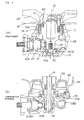
- Fig. 4 illustrates an embodiment of the final gear transmission mechanism according to the present invention and a comparative example.
- Fig. 4(a) illustrates the embodiment.
- the rear axle 25 can be held by the one-end holding portion 75 and the fastening member 73 not to be movable in the axial direction Ja of the rear axle 25. Therefore, the fastening rigidity of the rear axle 25 attached with the ring gear 68 can significantly be increased.
- a cylindrical ring gear shaft 93 corresponding to a rear axle 25B attached with a ring gear 68B is insertably fitted to an axial member 94 as a fixed shaft.
- the ring gear shaft 93 is disposed on the side of a wheel and held only by the side of a damper holder 96 having a damper member 95.
- the gear shaft 93 is not provided with a member for restricting the movement of an axial Jb direction from the outside of a vehicle.
- torque variations and/or velocity variations may probably cause the meshing state between the ring gear 68B and a pinion gear 47B to be easily variable. If the meshing state varies, for example, gear noise or the like occurs in some cases.
- the final gear transmission mechanism 65 includes the one-end holding portion 75 for holding the one-end 25a of the rear axle 25 attached with the ring gear 68 via the one-end bearings 71 in the axial direction of the rear axle 25; and the fastening member 73 for fastening the other-end bearing 72 to the other end 25b of the axle 25 from the outside of the gear case 61.
- the rear axle 25 can be held not to be movable in the axial Ja direction.
- the fastening rigidity of the rear axle 25 attached with the ring gear 68 can significantly be increased.
- the ring gear 68 is a member for transmitting the rotational drive force of the engine 16 to the rear axle 25, it is subjected to large force. Since the fastening rigidity of the rear axle 25 attached with the ring gear 68 is increased, the axially Ja directional movement of the ring gear 68 can be suppressed. If the axially Ja directional movement of the ring gear 68 can be suppressed, the meshing state between the ring gear 68 and the pinion gear 47 disposed closed to the drive shaft 44 to be meshed therewith becomes less variable. If the variation of the meshing state becomes hard to occur, the variation in drive torque becomes less variable, which allows for stable transmission of the drive force. In addition, gear noise with respect to the transmission of the rotational drive force can be reduced.
- the present invention is suitable for motorcycles having a final gear transmission mechanism.
- the invention is directed to provide a technology for increasing fastening rigidity of a rear axle attached with a ring gear to stabilize the meshing state between a ring gear and a pinion gear meshed with the ring gear in a motorcycle including a final gear transmission mechanism disposed therein.
- a final gear transmission mechanism 65 includes: a gear case 61 mounted to a leading end 18a of a swing arm 18 to support a rear axle 25; a one-end bearing 71 and the other-end bearing 72 for supporting one end 25a and the other end 25b, respectively, of the rear axle 25; a ring gear 68 mounted to the rear axle 25 to transmit the rotational drive force of an engine to the rear axle; a one-end holding portion 75 for holding the one end 25a of the rear axle via a one-end bearing 71 in the axial direction of the rear axle 25; and a fastening member 73 for fastening the other-end bearing 72 to the other end 25b of the rear axle from the outside of the gear case 61.
Landscapes
- Engineering & Computer Science (AREA)
- Mechanical Engineering (AREA)
- Chemical & Material Sciences (AREA)
- Combustion & Propulsion (AREA)
- Transportation (AREA)
- Axle Suspensions And Sidecars For Cycles (AREA)
- Motorcycle And Bicycle Frame (AREA)
- Braking Arrangements (AREA)
- Mounting Of Bearings Or Others (AREA)
Applications Claiming Priority (1)
| Application Number | Priority Date | Filing Date | Title |
|---|---|---|---|
| JP2008070236A JP5086855B2 (ja) | 2008-03-18 | 2008-03-18 | 自動二輪車 |
Publications (2)
| Publication Number | Publication Date |
|---|---|
| EP2103513A1 EP2103513A1 (en) | 2009-09-23 |
| EP2103513B1 true EP2103513B1 (en) | 2010-07-21 |
Family
ID=40581301
Family Applications (1)
| Application Number | Title | Priority Date | Filing Date |
|---|---|---|---|
| EP09000162A Expired - Fee Related EP2103513B1 (en) | 2008-03-18 | 2009-01-08 | Motorcycle |
Country Status (5)
| Country | Link |
|---|---|
| US (1) | US8002068B2 (ja) |
| EP (1) | EP2103513B1 (ja) |
| JP (1) | JP5086855B2 (ja) |
| CN (1) | CN101537872B (ja) |
| DE (1) | DE602009000066D1 (ja) |
Families Citing this family (8)
| Publication number | Priority date | Publication date | Assignee | Title |
|---|---|---|---|---|
| JP4394117B2 (ja) * | 2006-12-28 | 2010-01-06 | 本田技研工業株式会社 | シャフト駆動車両用スイングアーム構造 |
| WO2010018701A1 (ja) * | 2008-08-11 | 2010-02-18 | 本田技研工業株式会社 | 自動二輪車 |
| JP5123806B2 (ja) * | 2008-09-30 | 2013-01-23 | 本田技研工業株式会社 | シャフトドライブ式自動二輪車 |
| US10604203B2 (en) * | 2010-10-12 | 2020-03-31 | Weng-Dah Ken | Green bike |
| JP2012096613A (ja) * | 2010-10-29 | 2012-05-24 | Honda Motor Co Ltd | 電動車両 |
| ITPD20130309A1 (it) * | 2013-11-14 | 2015-05-15 | Piaggio & C Spa | Trasmissione motociclistica di tipo omocinetico, e motociclo comprendente detta trasmissione |
| JP6856687B2 (ja) | 2019-03-25 | 2021-04-07 | 本田技研工業株式会社 | 自動二輪車の後輪制動装置 |
| CN111440621B (zh) * | 2020-05-09 | 2023-08-25 | 大连华锐重工焦炉车辆设备有限公司 | 一种链条摆臂上升管高低压氨水开关控制装置 |
Family Cites Families (14)
| Publication number | Priority date | Publication date | Assignee | Title |
|---|---|---|---|---|
| US4436173A (en) * | 1981-05-15 | 1984-03-13 | Honda Giken Kogyo Kabushiki Kaisha | Shaft drive apparatus for motorized two-wheeled vehicle |
| JPS58167202A (ja) * | 1982-03-29 | 1983-10-03 | Yamaha Motor Co Ltd | 後二輪を備えるシヤフトドライブ式車両 |
| US4824252A (en) | 1982-06-25 | 1989-04-25 | Honeywell Inc. | Laser gyro system |
| JPS5981222A (ja) * | 1982-10-29 | 1984-05-10 | Yamaha Motor Co Ltd | シヤフトドライブ式車輛 |
| CA1249192A (en) * | 1984-09-14 | 1989-01-24 | Munenori Kiryu | Method and apparatus for cooling cylinder head of an engine |
| JPS61200075A (ja) * | 1985-03-04 | 1986-09-04 | ヤマハ発動機株式会社 | 不整地走行用自動二輪車 |
| JPH0616958Y2 (ja) | 1988-06-07 | 1994-05-02 | シンガー日綱株式会社 | タオル生地の曲り矯正装置 |
| JP4058884B2 (ja) * | 2000-05-23 | 2008-03-12 | スズキ株式会社 | 自動二輪車の後輪懸架装置 |
| CN1292956C (zh) | 2002-05-03 | 2007-01-03 | 摩托格兹公司 | 具有万向节传动轴的摩托车后车轴 |
| US7096846B1 (en) * | 2005-07-01 | 2006-08-29 | Harley-Davidson Motor Company Group, Inc. | Engine and transmission case assembly |
| JP4773220B2 (ja) * | 2006-01-31 | 2011-09-14 | 本田技研工業株式会社 | 後輪構造 |
| JP4733538B2 (ja) * | 2006-02-28 | 2011-07-27 | 本田技研工業株式会社 | 自動二輪車 |
| JP4814739B2 (ja) * | 2006-09-20 | 2011-11-16 | 本田技研工業株式会社 | 自動二輪車 |
| JP4864790B2 (ja) * | 2007-03-29 | 2012-02-01 | 本田技研工業株式会社 | シャフトドライブ式駆動装置のブリーザ構造 |
-
2008
- 2008-03-18 JP JP2008070236A patent/JP5086855B2/ja active Active
-
2009
- 2009-01-08 EP EP09000162A patent/EP2103513B1/en not_active Expired - Fee Related
- 2009-01-08 DE DE602009000066T patent/DE602009000066D1/de active Active
- 2009-02-18 US US12/378,688 patent/US8002068B2/en not_active Expired - Fee Related
- 2009-02-27 CN CN2009100068268A patent/CN101537872B/zh not_active Expired - Fee Related
Also Published As
| Publication number | Publication date |
|---|---|
| CN101537872B (zh) | 2012-01-11 |
| EP2103513A1 (en) | 2009-09-23 |
| US20090236168A1 (en) | 2009-09-24 |
| JP5086855B2 (ja) | 2012-11-28 |
| CN101537872A (zh) | 2009-09-23 |
| US8002068B2 (en) | 2011-08-23 |
| DE602009000066D1 (de) | 2010-09-02 |
| JP2009220786A (ja) | 2009-10-01 |
Similar Documents
| Publication | Publication Date | Title |
|---|---|---|
| EP2103513B1 (en) | Motorcycle | |
| US7946374B2 (en) | Vehicle | |
| EP1826110B1 (en) | Motorcycle with drive shaft | |
| US8474566B2 (en) | Shaft drive type motorcycle | |
| EP3305563B1 (en) | Vehicle steering system | |
| US7971674B2 (en) | Shaft drive type motorcycle | |
| EP2202140B1 (en) | Stroke distance sensor system | |
| JP2007098988A (ja) | 電動パワーステアリングユニット支持構造 | |
| JP5121526B2 (ja) | シャフトドライブ装置 | |
| WO2002028698B1 (en) | Two-wheel drive two-wheeled vehicle | |
| JP4814739B2 (ja) | 自動二輪車 | |
| JP2008110736A (ja) | 車両の操作レバー連結構造 | |
| EP3369649B1 (en) | Support structure of drive shaft | |
| JP6464130B2 (ja) | パルサーリング取付構造 | |
| JP2006096274A (ja) | 自動二,三輪車におけるスイングアームピボット構造及び自動二,三輪車 | |
| JP4881685B2 (ja) | 自動二輪車 | |
| JP5506223B2 (ja) | モータ駆動車両 | |
| JP5033456B2 (ja) | ステアリングダンパ取付構造 | |
| EP2767466B1 (en) | Final gear structure | |
| JP5258487B2 (ja) | シャフトドライブ式自動二輪車 | |
| JP2014162345A (ja) | ギヤボックス構造 | |
| JP5258486B2 (ja) | シャフトドライブ式自動二輪車 | |
| JP2016007932A (ja) | 動力伝達機構 |
Legal Events
| Date | Code | Title | Description |
|---|---|---|---|
| PUAI | Public reference made under article 153(3) epc to a published international application that has entered the european phase |
Free format text: ORIGINAL CODE: 0009012 |
|
| 17P | Request for examination filed |
Effective date: 20090108 |
|
| AK | Designated contracting states |
Kind code of ref document: A1 Designated state(s): AT BE BG CH CY CZ DE DK EE ES FI FR GB GR HR HU IE IS IT LI LT LU LV MC MK MT NL NO PL PT RO SE SI SK TR |
|
| AX | Request for extension of the european patent |
Extension state: AL BA RS |
|
| 17Q | First examination report despatched |
Effective date: 20090903 |
|
| GRAP | Despatch of communication of intention to grant a patent |
Free format text: ORIGINAL CODE: EPIDOSNIGR1 |
|
| GRAS | Grant fee paid |
Free format text: ORIGINAL CODE: EPIDOSNIGR3 |
|
| AKX | Designation fees paid |
Designated state(s): DE FR IT |
|
| RIN1 | Information on inventor provided before grant (corrected) |
Inventor name: NIMURA, TAISUKEC/O HONDA R&D CO., LTD. Inventor name: TOYODA, HIDETOSHIC/O HONDA R&D CO., LTD. Inventor name: SAKAI, KIYOTAKAC/O HONDA R&D CO., LTD. Inventor name: SHIOMI, YOSHINOBUC/O HONDA R&D CO., LTD. Inventor name: HIGASHI, YASUHIROC/O HONDA R&D CO., LTD. Inventor name: KOFUJI, KENJIC/O HONDA R&D CO., LTD. |
|
| GRAA | (expected) grant |
Free format text: ORIGINAL CODE: 0009210 |
|
| AK | Designated contracting states |
Kind code of ref document: B1 Designated state(s): DE FR IT |
|
| REF | Corresponds to: |
Ref document number: 602009000066 Country of ref document: DE Date of ref document: 20100902 Kind code of ref document: P |
|
| PLBE | No opposition filed within time limit |
Free format text: ORIGINAL CODE: 0009261 |
|
| STAA | Information on the status of an ep patent application or granted ep patent |
Free format text: STATUS: NO OPPOSITION FILED WITHIN TIME LIMIT |
|
| 26N | No opposition filed |
Effective date: 20110426 |
|
| REG | Reference to a national code |
Ref country code: DE Ref legal event code: R097 Ref document number: 602009000066 Country of ref document: DE Effective date: 20110426 |
|
| REG | Reference to a national code |
Ref country code: FR Ref legal event code: PLFP Year of fee payment: 8 |
|
| REG | Reference to a national code |
Ref country code: FR Ref legal event code: PLFP Year of fee payment: 9 |
|
| REG | Reference to a national code |
Ref country code: DE Ref legal event code: R084 Ref document number: 602009000066 Country of ref document: DE |
|
| REG | Reference to a national code |
Ref country code: FR Ref legal event code: PLFP Year of fee payment: 10 |
|
| PGFP | Annual fee paid to national office [announced via postgrant information from national office to epo] |
Ref country code: FR Payment date: 20181213 Year of fee payment: 11 |
|
| PGFP | Annual fee paid to national office [announced via postgrant information from national office to epo] |
Ref country code: FR Payment date: 20190124 Year of fee payment: 11 |
|
| PG25 | Lapsed in a contracting state [announced via postgrant information from national office to epo] |
Ref country code: FR Free format text: LAPSE BECAUSE OF NON-PAYMENT OF DUE FEES Effective date: 20200131 |
|
| PG25 | Lapsed in a contracting state [announced via postgrant information from national office to epo] |
Ref country code: IT Free format text: LAPSE BECAUSE OF NON-PAYMENT OF DUE FEES Effective date: 20200108 |
|
| PGFP | Annual fee paid to national office [announced via postgrant information from national office to epo] |
Ref country code: DE Payment date: 20211130 Year of fee payment: 14 |
|
| REG | Reference to a national code |
Ref country code: DE Ref legal event code: R119 Ref document number: 602009000066 Country of ref document: DE |
|
| PG25 | Lapsed in a contracting state [announced via postgrant information from national office to epo] |
Ref country code: DE Free format text: LAPSE BECAUSE OF NON-PAYMENT OF DUE FEES Effective date: 20230801 |