EP2103440B1 - Selectable gloss coating system - Google Patents
Selectable gloss coating system Download PDFInfo
- Publication number
- EP2103440B1 EP2103440B1 EP09155428.7A EP09155428A EP2103440B1 EP 2103440 B1 EP2103440 B1 EP 2103440B1 EP 09155428 A EP09155428 A EP 09155428A EP 2103440 B1 EP2103440 B1 EP 2103440B1
- Authority
- EP
- European Patent Office
- Prior art keywords
- gloss
- ink
- coating
- coating ink
- gloss coating
- Prior art date
- Legal status (The legal status is an assumption and is not a legal conclusion. Google has not performed a legal analysis and makes no representation as to the accuracy of the status listed.)
- Expired - Fee Related
Links
- 238000000576 coating method Methods 0.000 title claims description 176
- 239000011248 coating agent Substances 0.000 title claims description 174
- 238000002156 mixing Methods 0.000 claims description 61
- 238000003384 imaging method Methods 0.000 claims description 38
- 238000000034 method Methods 0.000 claims description 10
- 230000005855 radiation Effects 0.000 claims description 2
- 238000009434 installation Methods 0.000 claims 1
- 239000000976 ink Substances 0.000 description 194
- 239000007787 solid Substances 0.000 description 24
- 239000003086 colorant Substances 0.000 description 18
- 230000008859 change Effects 0.000 description 12
- 239000012071 phase Substances 0.000 description 12
- 230000037361 pathway Effects 0.000 description 11
- 238000007639 printing Methods 0.000 description 11
- 238000003860 storage Methods 0.000 description 5
- 238000010586 diagram Methods 0.000 description 4
- 238000007641 inkjet printing Methods 0.000 description 4
- 239000000203 mixture Substances 0.000 description 4
- 239000000758 substrate Substances 0.000 description 4
- VYPSYNLAJGMNEJ-UHFFFAOYSA-N Silicium dioxide Chemical compound O=[Si]=O VYPSYNLAJGMNEJ-UHFFFAOYSA-N 0.000 description 3
- 238000003491 array Methods 0.000 description 3
- 238000004140 cleaning Methods 0.000 description 3
- 230000001419 dependent effect Effects 0.000 description 3
- 238000010438 heat treatment Methods 0.000 description 3
- 239000000463 material Substances 0.000 description 3
- 238000002844 melting Methods 0.000 description 3
- 230000008018 melting Effects 0.000 description 3
- 230000008569 process Effects 0.000 description 3
- 239000003795 chemical substances by application Substances 0.000 description 2
- 239000007788 liquid Substances 0.000 description 2
- 239000007791 liquid phase Substances 0.000 description 2
- 239000002904 solvent Substances 0.000 description 2
- 239000005909 Kieselgur Substances 0.000 description 1
- TZCXTZWJZNENPQ-UHFFFAOYSA-L barium sulfate Chemical compound [Ba+2].[O-]S([O-])(=O)=O TZCXTZWJZNENPQ-UHFFFAOYSA-L 0.000 description 1
- 239000011230 binding agent Substances 0.000 description 1
- 230000015572 biosynthetic process Effects 0.000 description 1
- 238000006243 chemical reaction Methods 0.000 description 1
- 238000005520 cutting process Methods 0.000 description 1
- 238000002059 diagnostic imaging Methods 0.000 description 1
- 230000000694 effects Effects 0.000 description 1
- 230000005611 electricity Effects 0.000 description 1
- 238000005516 engineering process Methods 0.000 description 1
- 230000007613 environmental effect Effects 0.000 description 1
- 230000006870 function Effects 0.000 description 1
- 229910001385 heavy metal Inorganic materials 0.000 description 1
- 230000001788 irregular Effects 0.000 description 1
- 238000012423 maintenance Methods 0.000 description 1
- 238000005259 measurement Methods 0.000 description 1
- 230000007246 mechanism Effects 0.000 description 1
- 239000011236 particulate material Substances 0.000 description 1
- 239000004033 plastic Substances 0.000 description 1
- 239000011241 protective layer Substances 0.000 description 1
- 238000005086 pumping Methods 0.000 description 1
- 238000010926 purge Methods 0.000 description 1
- 239000000377 silicon dioxide Substances 0.000 description 1
- 239000000344 soap Substances 0.000 description 1
- 239000007790 solid phase Substances 0.000 description 1
- 230000007704 transition Effects 0.000 description 1
- 238000009966 trimming Methods 0.000 description 1
Images

Classifications
-
- B—PERFORMING OPERATIONS; TRANSPORTING
- B41—PRINTING; LINING MACHINES; TYPEWRITERS; STAMPS
- B41J—TYPEWRITERS; SELECTIVE PRINTING MECHANISMS, i.e. MECHANISMS PRINTING OTHERWISE THAN FROM A FORME; CORRECTION OF TYPOGRAPHICAL ERRORS
- B41J2/00—Typewriters or selective printing mechanisms characterised by the printing or marking process for which they are designed
- B41J2/005—Typewriters or selective printing mechanisms characterised by the printing or marking process for which they are designed characterised by bringing liquid or particles selectively into contact with a printing material
- B41J2/01—Ink jet
- B41J2/17—Ink jet characterised by ink handling
- B41J2/175—Ink supply systems ; Circuit parts therefor
- B41J2/17593—Supplying ink in a solid state
-
- B—PERFORMING OPERATIONS; TRANSPORTING
- B41—PRINTING; LINING MACHINES; TYPEWRITERS; STAMPS
- B41J—TYPEWRITERS; SELECTIVE PRINTING MECHANISMS, i.e. MECHANISMS PRINTING OTHERWISE THAN FROM A FORME; CORRECTION OF TYPOGRAPHICAL ERRORS
- B41J2/00—Typewriters or selective printing mechanisms characterised by the printing or marking process for which they are designed
- B41J2/005—Typewriters or selective printing mechanisms characterised by the printing or marking process for which they are designed characterised by bringing liquid or particles selectively into contact with a printing material
- B41J2/01—Ink jet
- B41J2/21—Ink jet for multi-colour printing
- B41J2/2107—Ink jet for multi-colour printing characterised by the ink properties
- B41J2/2114—Ejecting specialized liquids, e.g. transparent or processing liquids
-
- B—PERFORMING OPERATIONS; TRANSPORTING
- B41—PRINTING; LINING MACHINES; TYPEWRITERS; STAMPS
- B41J—TYPEWRITERS; SELECTIVE PRINTING MECHANISMS, i.e. MECHANISMS PRINTING OTHERWISE THAN FROM A FORME; CORRECTION OF TYPOGRAPHICAL ERRORS
- B41J2/00—Typewriters or selective printing mechanisms characterised by the printing or marking process for which they are designed
- B41J2/005—Typewriters or selective printing mechanisms characterised by the printing or marking process for which they are designed characterised by bringing liquid or particles selectively into contact with a printing material
- B41J2/01—Ink jet
- B41J2/135—Nozzles
- B41J2/14—Structure thereof only for on-demand ink jet heads
- B41J2/14016—Structure of bubble jet print heads
- B41J2/14032—Structure of the pressure chamber
- B41J2/1404—Geometrical characteristics
-
- B—PERFORMING OPERATIONS; TRANSPORTING
- B41—PRINTING; LINING MACHINES; TYPEWRITERS; STAMPS
- B41J—TYPEWRITERS; SELECTIVE PRINTING MECHANISMS, i.e. MECHANISMS PRINTING OTHERWISE THAN FROM A FORME; CORRECTION OF TYPOGRAPHICAL ERRORS
- B41J2/00—Typewriters or selective printing mechanisms characterised by the printing or marking process for which they are designed
- B41J2/005—Typewriters or selective printing mechanisms characterised by the printing or marking process for which they are designed characterised by bringing liquid or particles selectively into contact with a printing material
- B41J2/01—Ink jet
- B41J2/17—Ink jet characterised by ink handling
- B41J2/175—Ink supply systems ; Circuit parts therefor
- B41J2/17503—Ink cartridges
- B41J2/17506—Refilling of the cartridge
- B41J2/17509—Whilst mounted in the printer
-
- B—PERFORMING OPERATIONS; TRANSPORTING
- B41—PRINTING; LINING MACHINES; TYPEWRITERS; STAMPS
- B41J—TYPEWRITERS; SELECTIVE PRINTING MECHANISMS, i.e. MECHANISMS PRINTING OTHERWISE THAN FROM A FORME; CORRECTION OF TYPOGRAPHICAL ERRORS
- B41J2/00—Typewriters or selective printing mechanisms characterised by the printing or marking process for which they are designed
- B41J2/005—Typewriters or selective printing mechanisms characterised by the printing or marking process for which they are designed characterised by bringing liquid or particles selectively into contact with a printing material
- B41J2/01—Ink jet
- B41J2/17—Ink jet characterised by ink handling
- B41J2/175—Ink supply systems ; Circuit parts therefor
- B41J2/17503—Ink cartridges
- B41J2/1752—Mounting within the printer
- B41J2/17523—Ink connection
-
- B—PERFORMING OPERATIONS; TRANSPORTING
- B41—PRINTING; LINING MACHINES; TYPEWRITERS; STAMPS
- B41J—TYPEWRITERS; SELECTIVE PRINTING MECHANISMS, i.e. MECHANISMS PRINTING OTHERWISE THAN FROM A FORME; CORRECTION OF TYPOGRAPHICAL ERRORS
- B41J2/00—Typewriters or selective printing mechanisms characterised by the printing or marking process for which they are designed
- B41J2/005—Typewriters or selective printing mechanisms characterised by the printing or marking process for which they are designed characterised by bringing liquid or particles selectively into contact with a printing material
- B41J2/01—Ink jet
- B41J2/17—Ink jet characterised by ink handling
- B41J2/175—Ink supply systems ; Circuit parts therefor
- B41J2/17503—Ink cartridges
- B41J2/17556—Means for regulating the pressure in the cartridge
-
- B—PERFORMING OPERATIONS; TRANSPORTING
- B41—PRINTING; LINING MACHINES; TYPEWRITERS; STAMPS
- B41J—TYPEWRITERS; SELECTIVE PRINTING MECHANISMS, i.e. MECHANISMS PRINTING OTHERWISE THAN FROM A FORME; CORRECTION OF TYPOGRAPHICAL ERRORS
- B41J2/00—Typewriters or selective printing mechanisms characterised by the printing or marking process for which they are designed
- B41J2/005—Typewriters or selective printing mechanisms characterised by the printing or marking process for which they are designed characterised by bringing liquid or particles selectively into contact with a printing material
- B41J2/01—Ink jet
- B41J2/21—Ink jet for multi-colour printing
- B41J2/2107—Ink jet for multi-colour printing characterised by the ink properties
- B41J2/211—Mixing of inks, solvent or air prior to paper contact
-
- B—PERFORMING OPERATIONS; TRANSPORTING
- B41—PRINTING; LINING MACHINES; TYPEWRITERS; STAMPS
- B41J—TYPEWRITERS; SELECTIVE PRINTING MECHANISMS, i.e. MECHANISMS PRINTING OTHERWISE THAN FROM A FORME; CORRECTION OF TYPOGRAPHICAL ERRORS
- B41J2/00—Typewriters or selective printing mechanisms characterised by the printing or marking process for which they are designed
- B41J2/005—Typewriters or selective printing mechanisms characterised by the printing or marking process for which they are designed characterised by bringing liquid or particles selectively into contact with a printing material
- B41J2/01—Ink jet
- B41J2/21—Ink jet for multi-colour printing
- B41J2/2132—Print quality control characterised by dot disposition, e.g. for reducing white stripes or banding
- B41J2/2139—Compensation for malfunctioning nozzles creating dot place or dot size errors
-
- B—PERFORMING OPERATIONS; TRANSPORTING
- B41—PRINTING; LINING MACHINES; TYPEWRITERS; STAMPS
- B41J—TYPEWRITERS; SELECTIVE PRINTING MECHANISMS, i.e. MECHANISMS PRINTING OTHERWISE THAN FROM A FORME; CORRECTION OF TYPOGRAPHICAL ERRORS
- B41J29/00—Details of, or accessories for, typewriters or selective printing mechanisms not otherwise provided for
- B41J29/38—Drives, motors, controls or automatic cut-off devices for the entire printing mechanism
- B41J29/393—Devices for controlling or analysing the entire machine ; Controlling or analysing mechanical parameters involving printing of test patterns
-
- B—PERFORMING OPERATIONS; TRANSPORTING
- B41—PRINTING; LINING MACHINES; TYPEWRITERS; STAMPS
- B41M—PRINTING, DUPLICATING, MARKING, OR COPYING PROCESSES; COLOUR PRINTING
- B41M5/00—Duplicating or marking methods; Sheet materials for use therein
- B41M5/0023—Digital printing methods characterised by the inks used
Definitions
- This disclosure relates generally to inkjet printers, and, in particular, to inkjet printers that use coating inks.
- inkjet printing machines or printers include at least one printhead unit that ejects drops or jets of liquid ink onto an image receiving surface such as an image substrate.
- a phase change inkjet printer employs phase change inks that are in the solid phase at ambient temperature, but transition to a liquid phase at an elevated temperature. The melted ink can then be ejected as drops or jets by a printhead assembly onto an image substrate at the elevated operating temperature of the machine or printer.
- the image receiving surface may be a recording media in which case the ink can be ejected directly onto the image substrate, or, alternatively, an intermediate transfer surface in which case the ink is ejected onto the intermediate transfer surface and subsequently transferred to a recording media.
- Gloss is a measure of the reflective properties of a surface. High gloss indicates that the surface reflections are mirror-like or specular, where the angle of reflection closely matches the angle of incidence of light illuminating the surface. Low gloss indicates that the surface produces diffuse reflections where incident light is scattered over a broad range of angles during reflection. Gloss levels may be influences by both the type of colorant as well as type of media used to form the printed image. Controlling gloss levels of a printed image may be difficult because printed ink may cause a change in gloss relative to the unprinted media.
- variations in the density of the ink deposited on the media to form an image may cause corresponding variations in the gloss level of the printed image.
- the colors may vary widely in their levels of gloss, and there may be noticeable differences between the gloss levels of printed areas as opposed to non-printed areas of image. These variations in gloss levels across a printed image may not be acceptable to consumers.
- One method that has been used to control gloss levels of printed images is to coat the entire printed media with a colorless coating material that is designed to provide a protective layer on the printed media as well as to provide a substantially uniform gloss to the printed media.
- a colorless coating material that is designed to provide a protective layer on the printed media as well as to provide a substantially uniform gloss to the printed media.
- coating materials There are many types of coating materials that may be used.
- coating inks have been developed that are capable of being jetted using standard printheads. The composition of coating inks can be adjusted to provide substantially any level of gloss to a printed image such as high gloss, matte, satin, etc.
- consumers may desire to be able to select and print specific gloss levels to all or part of a printed image, page or print job.
- the various gloss levels e.g., high gloss, semi-gloss, matte, etc.
- printed text having a low gloss level may be easier to read than printed text having a high gloss level.
- printers are capable of providing only a single gloss finish to printed images, e.g., a high gloss finish.
- Some printers have been developed that are capable of providing multiple gloss finishes to printed images.
- a separate coating ink is typically provided for each desired gloss level. Because coating inks having different gloss levels are typically manufactured at an off-site location, supplies of each desired gloss coating ink may have to be ordered well in advance of their actual use. In addition, customers may be required to order large quantities of the different gloss inks from the supplier, which may be more than they require or cost more money than they desire to spend.
- US 6,059,404 describes method and apparatus for producing ink intensity modulated ink jet printing.
- a gray scale ink jet printing method and apparatus which produce a high quality images having varying color intensities are disclosed. This is achieved by using a clear phase change ink base and a plurality of colored phase change inks with varying amounts of black dye, thereby producing multiple gray scale levels of black in images with substantial contrast between the imaged and non-imaged areas that are used in medical diagnostic imaging applications.
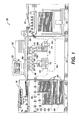
- FIG. 1 is a block diagram of a phase change imaging device that includes a coating system.
- FIG. 2 is a block diagram of one embodiment of the coating system of FIG. 1 .
- FIG. 3 is a block diagram of another embodiment of the coating system of FIG. 1 .
- imaging device generally refers to a device for applying an image to print media.
- Print media or “recording media” can be a physical sheet of paper, plastic, or other suitable physical print media substrate for images, whether precut or web fed.
- the imaging device may include a variety of other components, such as finishers, paper feeders, and the like, and may be embodied as a copier, printer, or a multifunction machine.
- a "print job” or “document” is normally a set of related sheets, usually one or more collated copy sets copied from a set of original print job sheets or electronic document page images, from a particular user, or otherwise related.
- An image generally may include information in electronic form which is to be rendered on the print media by the marking engine and may include text, graphics, pictures, and the like.
- gloss generally refers to the capacity of a surface to reflect more light in the specular direction as compared to other directions.
- Gloss level is a measurement of the degree of specular reflectance of a surface. Gloss levels are referred to with reference to gloss units as measured by a conventional gloss meter, such as a Gardner gloss meter, that measures the gloss level at a specific angle of incidence with respect to the surface, e.g., 20 degree, 30 degree, 45 degree, 60 degree, 75 degree and 80 degree, etc.
- the exemplary imaging device includes a print station 12 that includes at least one printhead module 24, 26 for emitting ink onto print media to form images.
- the print station 12 also includes a coating system 100 for providing a customer selectable coating to printed media.
- the coating system 100 includes a high gloss ink and a low gloss ink for providing a high gloss coating and a low gloss coating, respectively.
- the coating system 100 is configured to mix the high and low gloss coating inks in the printer to form at least one intermediate gloss coating for use on the printed media.
- the print station 12 is interposed between a feeder module 14 and a finishing module 16.
- the print station 12 is fed with print media from the feeder module 14 as is known in the art.
- the feeder module 14 may include a plurality of print media sources such as trays 30.
- Each feeder tray 30, may include print media having different attributes such as roughness, coats, weights and the like.
- the print media may be substantially any type of media upon which the printhead modules may print, such as: high quality bond paper, lower quality "copy" paper, overhead transparency sheets, high gloss paper, etc.
- the printer 10 may be a web fed printer in which the feeder module 14 is configured to feed a continuous web of material, such as a roll of paper, a supply roller, or the like, (not shown) to the print station which may then be taken up on a take up roller or post-processed by, for example, cutting or trimming as needed at the finishing module.
- a continuous web of material such as a roll of paper, a supply roller, or the like
- the finisher module 16 receives the print media from the print station 12.
- the term "finisher” or “finishing module” as broadly used herein in connection with the exemplary embodiment or embodiments disclosed herein, is any post-printing accessory device such as an inverter, reverter, sorter, mailbox, inserter, interposer, folder, stapler, collator, stitcher, binder, over-printer, envelope stuffer, postage machine, output tray, or the like.
- the finisher module 16 includes an output tray 34 to which received print media sheets can be delivered.
- the finisher module 16 may be configured to provide various finishes to the print media sheets of a print job or jobs, or even a portion of a print job.
- Possible finishes that may be performed by the finisher can include, for example, patterns of collation, binding or stapling available by the finisher module. Additional, advanced finishes can include, for example, other binding techniques, shrink wrapping, various folding formats, etc.
- the finisher module 16 can also be provided with multiple output trays (not shown) and the ability to deliver specified print media sheets to a selected output tray or trays.
- a print media transporting system links the feeder module 14, print station 12, and finisher module 16.
- the print media transporting system includes a network of media pathways 38 for guiding the movement of the print media through the imaging device 10.
- the print media transporting system may comprise drive members, such as pairs of rollers, spherical nips, airjets, or the like.
- the transport system may further include associated motors for the drive members, belts, guide rods, frames, etc. (not shown), which, in combination with the drive members, serve to convey the print media along selected pathways at selected speeds.
- the print media from the source 14 is delivered to the print station 12 by a pathway which is common to the trays 30.
- the print media is printed on by the printhead modules of the print station 12 that are arranged along the media pathway 38.
- the pathway 38 also conveys the printed media to the finisher 38.
- the print station 12 may also include a fixing assembly 44 for fixing the emitted ink drops, or image, to the web.
- the fixing assembly 44 may be any suitable type of device or apparatus, as is known in the art, which is capable of fixing the image to the media.
- the type of fixing assembly is dependent upon the type(s) of ink that are used in the imaging device.
- the fixing assembly may comprise a pair fixing rollers (not shown) that are positioned in relation to each other to form a nip through which the media is fed. The ink drops on the media are pressed into the media and spread out on the media by the pressure formed by the nip.
- the fixing assembly may include a dryer or heater for applying heat to the printed ink in order to fix the ink to the media.
- the fixing assembly may include a UV lamp for applying ultraviolet radiation to the printed ink.
- the controller 20 may be implemented as hardware, software, firmware or any combination thereof.
- the controller 20 comprises a self-contained, microcomputer having a central processor unit (not shown) and electronic storage (not shown).
- the electronic storage may store data necessary for the controller such as, for example, the image data, component control protocols, etc.
- the electronic storage may be a non-volatile memory such as a read only memory (ROM) or a programmable non-volatile memory such as an EEPROM or flash memory.
- ROM read only memory
- EEPROM electrically erasable programmable non-volatile memory
- the electronic storage may be incorporated into the inkjet printer, or may be externally located.
- the controller 20 receives image data from an image data source.
- the image data source may be any one of a number of different sources, such as a scanner, a digital copier, a facsimile device that is suitable for generating electronic image data, or a device suitable for storing and/or transmitting electronic image data, such as a client or server of a network, or the Internet.
- the controller 20 may use a color conversion process to convert the color specifications in the image data to the color space that is capable of being printed by the imaging device 10.
- the controller may be configured to implement a halftone imaging process as is known in the art to produce the desired color based on the input color value.
- the controller may be configured to convert a color space of the image to be rendered into halftone densities of a plurality of colorants available within the imaging device.
- the print station 12 includes multiple printhead modules 24, 26 for emitting ink onto the print media in accordance with the image data.
- print station is configured to implement a solid ink printing process to print images onto the print media.
- the printhead modules of the print station are configured as phase change ink, or solid ink, printhead modules.
- Each printhead module is appropriately supported adjacent the media pathway for emitting drops of ink directly onto the print media as the media moves through the print zone 18.
- the printhead assembly may be configured to emit drops onto an intermediate transfer member (not shown), such as a drum or belt, for subsequent transfer to the media.
- the ink supply 48 includes a plurality of solid ink sources 50, 54, 58, 60 which are each configured to supply a different color of ink to the printhead modules 24, 26.
- each solid ink source 50, 54, 58, 60 of the solid ink supply comprises a dedicated channel for loading, feeding, and melting solid ink sticks of a particular color.
- the respective ink channels 50, 54, 58, 60 guide the appropriate colored solid ink sticks to a melting and control assembly or apparatus (not shown) for melting or phase changing the solid form of the phase change ink into a liquid form, and then supplying the liquid phase change ink to the printhead modules.
- the solid ink sticks utilized in the imaging device may be standard colors (e.g., cyan, magenta, yellow, or black).
- the solid ink supply 48 includes four sources representing the four CMYK colors (cyan, yellow, magenta, black) of solid ink.
- the system may be adapted for a higher or lower number of different colored solid inks.
- the imaging device may be configured with an expanded color gamut that includes solid inks of other colors in addition to the CMYK colors.
- the solid ink supply includes solid ink sources (not shown) for supplying light cyan, light magenta, orange and green (cmOG) although any color may be used.
- cmOG blue and green
- the imaging device may include solid ink sources for supplying premixed custom color ink which may be substantially any color. Any suitable number of solid ink sources and/or combinations of different colors of ink (e.g., standard CMYK, expanded gamut cmOG, or premixed colors) may be utilized in the imaging device 10. The total number of different colors and combination of colors of solid ink made available in the system 10 may be dependent upon the overall number and range of colors desired to be printed.
- Each printhead module 24, 26 is configured to receive at least one of the colors of ink from the solid ink supply and to emit the ink onto the media. Accordingly, each printhead module 24, 26 includes at least one printhead having a plurality of inkjet nozzles for ejecting the ink received from the solid ink supply. In one embodiment, each printhead 24, 26, is configured to eject ink by displacing ink in an ink pressure chamber thereby ejecting ink droplets. As is known in the art, a drive mechanism, such as a piezoelectric transducer bonded to a thin diaphragm, may be used to displace the ink in the pressure chamber. The controller 20 is configured to generate driving signals for driving the inkjets of the printhead modules to expel ink from the inkjets in the printheads to form an image on the print media in accordance with the image data.
- CMYK printhead module 24 includes a printhead for each of the CMYK colors, i.e., a printhead for emitting cyan ink, a printhead for emitting magenta ink, a printhead for emitting yellow ink and a printhead for emitting black ink.
- the expanded gamut printhead module includes a printhead for each of the colors in the expanded color gamut (cmOG), i.e., a printhead for emitting light cyan ink, a printhead for emitting light magenta ink, a printhead for emitting orange ink and a printhead for emitting green ink.
- a printhead for emitting light cyan ink i.e., a printhead for emitting light cyan ink
- a printhead for emitting light magenta ink i.e., a printhead for emitting light magenta ink
- a printhead for emitting orange ink a printhead for emitting green ink.
- the CMYK printhead module and cmOG printhead module have been described as having a separate printhead for each color of ink, other arrangements are contemplated.
- each printhead module may comprise a single printhead having a dedicated array of inkjet nozzles for ejecting each color of ink received from the solid ink supply, i.e., an array of nozzles for ejecting cyan ink, an array of nozzles for ejecting magenta ink, etc.
- the printheads utilized in the printhead modules may have any suitable configuration such as page-width array, partial page-width array, and carriage type printheads.
- a printhead module may have at least one page-width array printhead for each color of ink associated with the printhead module.
- a printhead module may have a plurality of partial-width array printheads for each color associated with the printhead with the plurality of partial-width array printheads being arranged end-to-end in a straight line or staggered formation for spanning the media pathway of the imaging device.
- the printhead modules may be mounted on a carriage or similar support structure so that the printheads of the printhead module may be moved with respect to the media.
- a plurality of possible arrangements and configurations for the printheads of the printhead modules are possible and are contemplated within the scope of this disclosure.
- the inkjet imaging device of FIG. 1 includes a coating system 100.
- the coating system has a coating ink supply source 104 that is configured to supply at least two colorless coating inks, each coating ink being configured to provide a different gloss level to a printed image.
- the coating ink supply source 104 is configured to supply a high gloss coating ink 108 and a low gloss coating ink 110.
- the high gloss coating ink is for providing a glossy finish to all or parts of a printed image, page, job, etc.
- the low gloss coating ink is for providing a low gloss, or matte, finish to all or parts of a printed image, page, job, etc.
- the high and low gloss levels may be any suitable level.
- the high gloss level may be greater than approximately 60 gloss units while the low gloss level may be less than approximately 20 gloss units.
- the high and low gloss coating inks may have any suitable composition that is capable of producing the desired gloss level.
- the coating inks may be printed with the same type of printheads that are used for the colored ink.
- the coating inks comprise a curable ink, such as UV curable inks or Hybrid UV curable inks. Any suitable type of ink, however, may be used including solid inks, aqueous inks, solvent based inks, etc.
- the high and low gloss coating inks may each have substantially the same composition except that the low gloss coating ink may include flatting or dulling agents, as are known in the art, to reduce the gloss level of the low gloss coating ink. Flatting agents, such as silica, barytes, diatomaceous earth and heavy metal soaps, are finely divided particulate materials of irregular shape which tend to dull the surface appearance of the cured coating by dispersing incident light rays.
- the coating system 100 is configured to mix an intermediate gloss coating ink in the printer from the high gloss and low gloss coating inks that are preloaded into the imaging device. Accordingly, the high gloss coating ink and the low gloss coating ink are mixable to produce an intermediate gloss coating that has a gloss level corresponding to the relative percentages of the high and low gloss coating inks in the mixture.
- the term "intermediate gloss,” as used herein, may generally refer to any gloss level that is between the high gloss level and the low gloss level provided by the high gloss coating ink and the low gloss coating ink, respectively.
- the intermediate gloss level may be any value between approximately 10 and 90 gloss units.
- the coating system includes a coating module 102 with a printhead 112 having an array of inkjet nozzles 114 for emitting the high gloss ink, an array of inkjet nozzles 118 for emitting the low gloss ink, a mixing reservoir 124 for mixing measured quantities of the high gloss ink and low gloss ink to form an intermediate gloss ink, and an array of inkjet nozzles 120 for emitting the intermediate gloss ink.
- the mixing reservoir 124 is configured to receive the high gloss coating ink and the low gloss coating ink from the respective supply sources 108, 110 and to mix the different coating inks to form an intermediate gloss coating ink.
- the mixing reservoir includes a pair of coating ink supply inlets 132, 134 that are configured to receive the coating ink from the ink sources.
- the coating system 100 includes dispensers for controlling the flow of the coating inks the mixing reservoir via the ink supply inlets.
- the custom color printhead module of FIG. 2 includes dispensers 128, 130 for controlling the flow of ink into the mixing reservoir from each of the high gloss ink source and the low gloss ink source.
- the coating module may include dispensers 129, 131 for controlling the flow of the ink from the gloss ink sources to the respective high and low gloss nozzles of the printhead.
- the flow rates of the inks through the dispensers may be determined in any suitable manner as is known in the art so that the quantities of the inks that are dispensed into the mixing reservoir may be accurately controlled.
- the dispensers 128, 129, 130, 131 may comprise one-way dispensing valves that open and close to control the flow of ink from an associated ink supply source to the mixing reservoir 124 or the respective high and low gloss inkjet arrays.
- the dispensers may comprise any suitable device or structure that is capable of controlling and/or metering the ink from the respective ink supply sources.
- the dispensers may include pumps, pressure sensors, temperature sensors, etc. for facilitating the accurate dispensing of the inks into the reservoir.
- the mixing reservoir 124 may comprise any suitable container or structure capable of holding the coating inks received via the dispensers.
- the mixing reservoir may be any size. In the embodiment of FIG. 2 , the mixing reservoir is configured to hold approximately 10ml of ink. The relatively small size of the reservoir allows for faster mixing of the component gloss coating inks and minimizes the amount of the mixed gloss coating ink that has to be maintained in the reservoir ready for printing so that the ink is not wasted.
- the mixing reservoir 124 may include one or more mixing elements 138, which may be, for example, mechanical, magnetic, pneumatic, hydraulic, or ultrasonic stirrers, powered by electricity or other suitable source. The mixing element 138 is configured to commingle the different quantities of the high gloss and low gloss coating inks in the mixing reservoir to form an intermediate gloss coating ink.
- the mixing reservoir 124 is connected to the printhead array 120 via a supply conduit 140.
- the intermediate gloss coating ink in the mixing reservoir 124 may be supplied to the printhead array 120 as needed for printing onto the print media.
- the system may include a dispenser 144 for enabling and disabling the flow of the coating ink into the printhead array 120 from the mixing reservoir 124.
- the printhead 112 of the coating system may be configured for removal from the housing 170. Accordingly, the dispenser 144 may be configured as a disconnect valve to allow the printhead to be easily removed from the mixing reservoir 124.
- the module may include disconnect valves 142, 146 for removably connecting the supply lines of the gloss inks to the high and low gloss inkjet arrays.
- disconnect valves 142, 144, and 146 enable the removal of the printhead from the coating module for cleaning, replacement, maintenance, etc.
- the disconnect valves are advantageously configured to prevent the flow of ink from the mixing reservoir or ink sources when the printhead is removed from the module.
- FIG. 3 shows an alternative embodiment of the coating system 100' which includes a high gloss printhead 160, a low gloss printhead 164 and an intermediate gloss coating module 102' that includes a printhead 168.
- the printhead 168 may be configured for removal or replacement from the coating module 102'.
- the printhead used in the coating system may be similar or even identical to the printheads used in the standard printhead modules.
- the coating module 102' may comprise a "carrier" that accepts a standard ink jet printhead.
- the supply valve 144 may be configured as a disconnect valve to allow the printhead to be easily removed from the coating module.
- the disconnect valve is advantageously configured to prevent the flow of ink from the mixing reservoir through the custom color supply conduit when the printhead is removed from the module.
- the coating system 100, 100' may include a mixing controller 150.
- the mixing controller 150 is configured to control the dispensers 128, 130 to dispense measured quantities of each component coating ink into the mixing reservoir to form a gloss coating ink having a target gloss level.
- the mixing controller 150 controls the mixing element 138 in the reservoir 124 to mix the component inks to form the target gloss ink.
- the relative percentages of each of the high gloss ink and the low gloss ink that are required to form a target intermediate gloss ink may be determined with reference to a gloss level identifier for the intermediate gloss coating ink.
- the gloss level identifier may have associated mixing data that specifies the flow rates of each gloss coating ink, durations for opening the valves 128, 130 in order to dispense the appropriate concentrations of each component gloss ink into the mixing reservoir, duration of the mixing phase, etc. All of the possible gloss level identifiers and associated mixing data may be stored in memory in a data structure such as a database or table.
- the mixing controller 150 may use the gloss level identifier as a lookup key for accessing the data structure to retrieve the mixing data associated with the particular identifier.
- the mixing controller 150 controls the dispensers 128, 130 in order to dispense measured quantities of the high gloss coating ink and the low gloss coating ink into the mixing reservoir according to mixing data and controls the mixing element to mix the component gloss inks to form the target intermediate gloss ink.
- Mixing data may be determined for each desired level of intermediate gloss in any suitable manner. For example, the mixing data may be determined empirically and subsequently stored in the memory of the imaging device for access by the controller 150.
- the mixing reservoir 124 may also include a level sensor (not shown) for sensing a level of the intermediate gloss ink within the mixing reservoir 124.
- the controller 150 is configured to monitor the ink level in the mixing reservoir 124 to ensure that the mixing reservoir is constantly replenished by the component gloss inks in the ratios that are defined by the mixing data corresponding to the desired intermediate gloss ink. For example, as printing activities continue, the controller 150 monitors the level of the mixed ink in the mixing reservoir 124 via the level sensor and controls the appropriate dispensers 128, 130 to replenish the mixing reservoir 124 with the appropriate amounts of the component gloss inks as the ink is printed.
- the mixing controller 150 is configured to maintain the intermediate gloss ink at a substantially consistent gloss level in the mixing reservoir as well as maintain a substantially constant level of ink within the reservoir. Over time, the output of the imaging device may drift (or deviate from predetermined optimum standards) due to various factors. These factors include environmental conditions (temperature, relative humidity, etc.), use patterns, the type of media (e.g., different paper types and paper batches, transparencies, etc.) used, variations in media, general wear, etc. Accordingly, the mixing controller may be configured to monitor the gloss levels printed by the coating system to detect deviations from a target gloss level. The gloss level of the coating inks printed by the coating system may be measured by positioning a glossmeter adjacent to the media pathway downstream from the coating system.
- the imaging device 10 may include a glossmeter 154 positioned adjacent the media pathway downstream from the coating system 100 to measure the gloss level on the printed media. The measured gloss level may be compared to the target gloss level to detect deviations in the gloss level from the target gloss level. Based on the differences between the target gloss level and the actual printed gloss level, the mixing controller 150 may adjust the mixing data and save the adjustments so that the adjusted mixing data may be utilized the next time the particular gloss level is desired.
- the coating system may be configured to mix and print with multiple different intermediate gloss coating inks at a time by including a dedicated printhead or printhead array for each desired intermediate gloss level.
- the coating system may include a first intermediate gloss coating module for mixing and printing a low to intermediate gloss ink and a second intermediate gloss coating module for mixing and printing an intermediate to high gloss ink. Any suitable number of different gloss levels may be achieved using the coating system. As the number of different gloss levels that are available increases, the gradation of the gloss on the printed media may be more continuous.
- the coating modules 102, 102' may be removable for storage outside the imaging device, and/or to enable swapping of coating modules. By configuring the coating modules 102, 102' as removable or replaceable, the range of gloss levels that are capable of being applied by the imaging device may be increased without increasing the size or complexity of the imaging device.
- the housing 170 of the coating modules may be configured for releasable connection to the print station of the imaging device in any suitable manner.
- the print station may include module positions or slots that are configured to releasably secure a custom color module in an operable position adjacent the media pathway in the print station.
- the housings for separate coating modules are similarly sized so that the modules may be swapped or replaced as needed.
- the dispensers that control the flow of ink into the mixing reservoir of a custom color module may be configured as disconnect valves so that the supply lines may be removed from the modules prior to removal.
- the disconnect valves are advantageously configured to prevent the custom color ink from leading from the mixing reservoir when the custom color module is removed from the imaging device.
- the imaging device 10 may be reconfigured at any time to suit the particular print jobs to be handled.
- a user may have a particular print job which requires a coating having a specific gloss level not provided by any of the coating modules currently in the system.
- the user may switch one of the existing coating module for a coating module having the desired gloss level capabilities. This may be achieved without stopping printing operations by scheduling the changeover for a period of time when the remaining coating modules can handle the requirements of the jobs being printed at the time.
- the module When a coating module is removed from the imaging device, the module may be placed in a cleaning unit (not shown) which may be configured to purge the ink from the module.
- a printer user may put a new, clean coating module into the imaging device and program it for a particular gloss level while the previous module is being cleaned and purged.
- the cleaning unit configuration may have any suitable configuration and may contain solvents for pumping through the printhead. Once cleaned, a coating module may be used to apply the same gloss level coating or a different gloss level coating.
- the coating system has been described with reference to a phase change inkjet printer; however, the coating system may also be used in other types of inkjet printers where one desires to be able to mix and print multiple gloss level coatings from a preloaded set of gloss inks.
Landscapes
- Engineering & Computer Science (AREA)
- Quality & Reliability (AREA)
- Physics & Mathematics (AREA)
- Geometry (AREA)
- Ink Jet (AREA)
- Nozzles (AREA)
- Coating Apparatus (AREA)
Applications Claiming Priority (1)
| Application Number | Priority Date | Filing Date | Title |
|---|---|---|---|
| US12/050,726 US7934785B2 (en) | 2008-03-18 | 2008-03-18 | Selectable gloss coating system |
Publications (3)
| Publication Number | Publication Date |
|---|---|
| EP2103440A2 EP2103440A2 (en) | 2009-09-23 |
| EP2103440A3 EP2103440A3 (en) | 2010-06-09 |
| EP2103440B1 true EP2103440B1 (en) | 2013-12-04 |
Family
ID=40742528
Family Applications (1)
| Application Number | Title | Priority Date | Filing Date |
|---|---|---|---|
| EP09155428.7A Expired - Fee Related EP2103440B1 (en) | 2008-03-18 | 2009-03-18 | Selectable gloss coating system |
Country Status (4)
| Country | Link |
|---|---|
| US (1) | US7934785B2 (ja) |
| EP (1) | EP2103440B1 (ja) |
| JP (1) | JP4951641B2 (ja) |
| KR (1) | KR101464945B1 (ja) |
Families Citing this family (20)
| Publication number | Priority date | Publication date | Assignee | Title |
|---|---|---|---|---|
| US7934785B2 (en) | 2008-03-18 | 2011-05-03 | Xerox Corporation | Selectable gloss coating system |
| US8540357B2 (en) * | 2009-11-12 | 2013-09-24 | Xerox Corporation | Dithered printing of clear ink to reduce rub and offset |
| WO2011061136A1 (en) * | 2009-11-18 | 2011-05-26 | Oce-Technologies B.V. | Method for applying a curable hot-melt ink on a medium |
| US8465118B2 (en) * | 2010-06-14 | 2013-06-18 | Hewlett-Packard Development Company, L.P. | Printing system |
| US8651657B2 (en) * | 2010-10-21 | 2014-02-18 | Hewlett-Packard Development Company, L.P. | Printer module with bumper |
| US8608272B2 (en) | 2010-12-03 | 2013-12-17 | Xerox Corporation | System and method for inkjet printing with a differential halftoned protective overcoat with gloss compensation |
| JP2012159743A (ja) * | 2011-02-01 | 2012-08-23 | Fuji Xerox Co Ltd | 画像形成装置および記録媒体 |
| JP5875276B2 (ja) * | 2011-07-29 | 2016-03-02 | キヤノン株式会社 | プリント装置 |
| US9260616B2 (en) | 2012-02-29 | 2016-02-16 | Electronics For Imaging, Inc. | Gloss-controllable, radiation-curable inkjet ink |
| US8814314B2 (en) | 2012-08-24 | 2014-08-26 | Xerox Corporation | Method and apparatus for control of gloss level in printed images |
| JP6264860B2 (ja) * | 2013-11-27 | 2018-01-24 | セイコーエプソン株式会社 | 記録装置 |
| WO2016164562A1 (en) | 2015-04-07 | 2016-10-13 | President And Fellows Of Harvard College | Microfluidic active mixing nozzle for three-dimensional printing of viscoelastic inks |
| JP6682331B2 (ja) * | 2015-04-16 | 2020-04-15 | キヤノン株式会社 | インクジェット記録方法 |
| JP6679243B2 (ja) * | 2015-08-27 | 2020-04-15 | キヤノン株式会社 | 画像形成装置及び画像形成方法 |
| DE102015218325A1 (de) * | 2015-09-24 | 2017-03-30 | Bhs Corrugated Maschinen- Und Anlagenbau Gmbh | Wellpappe-Anlage |
| US10084619B2 (en) | 2016-06-03 | 2018-09-25 | International Business Machines Corporation | Nested feed-forward optical equalization using an electro-optic modulator with a multi-segment electrode |
| US10120210B2 (en) | 2016-06-03 | 2018-11-06 | International Business Machines Corporation | Feed-forward optical equalization using an electro-optic modulator with a multi-segment electrode and distributed drivers |
| JP6846204B2 (ja) * | 2017-01-06 | 2021-03-24 | 株式会社ミマキエンジニアリング | 印刷装置、印刷方法及び装飾物の製造方法 |
| EP3378665B1 (en) * | 2017-03-20 | 2020-09-23 | Canon Production Printing Holding B.V. | Method for applying an image of a radiation curable ink having a predetermined gloss |
| DE102022114231A1 (de) * | 2022-06-07 | 2023-12-07 | Homag Gmbh | Verfahren zum Bemustern eines Werkstücks |
Family Cites Families (48)
| Publication number | Priority date | Publication date | Assignee | Title |
|---|---|---|---|---|
| DE3014114C2 (de) | 1980-04-12 | 1982-04-29 | Gema AG Apparatebau, 9015 St. Gallen | Einrichtung zum automatischen Beschichten von Gegenständen mit einer Spritzvorrichtung |
| US5196236A (en) | 1984-12-31 | 1993-03-23 | Howtek, Inc. | Ink jet color printing method |
| JPH01118444A (ja) * | 1987-10-31 | 1989-05-10 | Canon Inc | 階調記録インクジェットプリンタ |
| JPH04355156A (ja) * | 1991-05-31 | 1992-12-09 | Canon Inc | インクジェット記録装置 |
| DE69422483T2 (de) | 1993-11-30 | 2000-10-12 | Hewlett Packard Co | Farbtintenstrahldruckverfahren und -vorrichtung unter Verwendung eines farblosen Vorläufers |
| US6102537A (en) | 1995-02-13 | 2000-08-15 | Canon Kabushiki Kaisha | Method and apparatus for ink-jet printing |
| US6059404A (en) * | 1995-06-06 | 2000-05-09 | Xerox Corporation | Method and apparatus for producing ink intensity modulated ink jet printing |
| JPH10202984A (ja) | 1997-01-28 | 1998-08-04 | Olympus Optical Co Ltd | プリントシート用コーティング装置 |
| US6170881B1 (en) | 1997-02-03 | 2001-01-09 | Serigraph, Inc. | Pseudo three-dimensional image display and method of manufacturing including reflective monochrome or holographic roll leafing |
| US5847738A (en) | 1997-07-11 | 1998-12-08 | Eastman Kodak Company | Process for applying protective overcoat on printed media |
| US6249355B1 (en) | 1998-10-26 | 2001-06-19 | Hewlett-Packard Company | System providing hybrid halftone |
| US6369844B1 (en) | 2000-08-11 | 2002-04-09 | Eastman Kodak Company | Laser imaging process |
| US6393844B1 (en) * | 2000-08-22 | 2002-05-28 | Raytheon Company | Pulse tube expander having a porous plug phase shifter |
| US20020156153A1 (en) | 2001-01-16 | 2002-10-24 | Tsang Joseph W. | Polymeric additives to improve print quality and permanence attributes in ink-jet inks |
| CN1240548C (zh) | 2001-04-24 | 2006-02-08 | 精工爱普生株式会社 | 喷墨记录方法和使用这些的记录物 |
| US7184177B2 (en) | 2001-06-06 | 2007-02-27 | International Business Machines Corporation | Method, apparatus and article of manufacture for modifying printing based upon direct on-the-fly media characteristic parameters |
| US7338143B2 (en) | 2001-10-12 | 2008-03-04 | Seiko Epson Corporation | Ink jet recording apparatus and recording method of the recording apparatus |
| JP4073200B2 (ja) * | 2001-11-08 | 2008-04-09 | 富士フイルム株式会社 | 画像記録方法およびインクジェットプリンタ |
| US7463376B2 (en) | 2002-01-30 | 2008-12-09 | Hewlett-Packard Development Company, L.P. | Print finishing method and apparatus |
| US7180635B2 (en) | 2002-05-30 | 2007-02-20 | Xerox Corporation | Halftone image gloss control for glossmarks |
| JP4040417B2 (ja) * | 2002-09-30 | 2008-01-30 | キヤノン株式会社 | 印刷物製造方法および印刷物製造装置 |
| US6939002B2 (en) | 2002-10-11 | 2005-09-06 | Eastman Kodak Company | Method and apparatus for producing a selectable gloss finish on ink jet prints |
| JP2004151268A (ja) | 2002-10-29 | 2004-05-27 | Fuji Xerox Co Ltd | 透明コート層形成装置及びこれを用いたカラー画像形成装置 |
| US6993272B2 (en) | 2002-11-07 | 2006-01-31 | Xerox Corporation | Method of development of custom colors without changing developer housing |
| US6925281B2 (en) | 2002-12-12 | 2005-08-02 | Xerox Corporation | Method and apparatus for finishing a receiver sheet or similar substrate |
| JPWO2004069543A1 (ja) * | 2003-02-04 | 2006-05-25 | コニカミノルタホールディングス株式会社 | インクジェット記録方法及びインクジェットプリンタ |
| JP4388754B2 (ja) * | 2003-03-25 | 2009-12-24 | 富士フイルム株式会社 | 表面処理装置およびプリンタ |
| JP4261980B2 (ja) | 2003-05-16 | 2009-05-13 | キヤノン株式会社 | 画像形成方法 |
| JP2005067054A (ja) | 2003-08-26 | 2005-03-17 | Seiko Epson Corp | 改善インクの吐出制御 |
| JP2005074878A (ja) | 2003-09-02 | 2005-03-24 | Konica Minolta Medical & Graphic Inc | 画像記録装置 |
| JP4209371B2 (ja) * | 2003-09-17 | 2009-01-14 | 富士フイルム株式会社 | 画像形成方法および画像形成装置 |
| JP2005088342A (ja) | 2003-09-17 | 2005-04-07 | Seiko Epson Corp | 改善インクの減色処理 |
| JP2005119279A (ja) | 2003-09-24 | 2005-05-12 | Seiko Epson Corp | 印刷装置、印刷制御装置、印刷制御方法および印刷装置制御プログラム |
| US7352493B2 (en) | 2003-12-12 | 2008-04-01 | Xerox Corporation | Enhancement of glossmark images at low and high densities |
| US7382495B2 (en) | 2003-12-12 | 2008-06-03 | Xerox Corporation | Reduction of differential gloss |
| JP4561103B2 (ja) | 2004-01-16 | 2010-10-13 | コニカミノルタエムジー株式会社 | インクジェット記録装置 |
| US7275804B2 (en) | 2004-02-12 | 2007-10-02 | Konica Minolta Medical & Graphic, Inc. | Inkjet recording apparatus |
| US7510277B2 (en) | 2004-03-01 | 2009-03-31 | Fujifilm Corporation | Image forming apparatus and method |
| US7301675B2 (en) | 2004-06-29 | 2007-11-27 | Xerox Corporation | Glossmark images with clear toner |
| US7304770B2 (en) | 2004-08-30 | 2007-12-04 | Xerox Corporation | Reduction of differential gloss with halftoned clear toner |
| US7324241B2 (en) | 2004-09-29 | 2008-01-29 | Xerox Corporation | Variable data differential gloss images |
| JP2006241345A (ja) * | 2005-03-04 | 2006-09-14 | Fuji Photo Film Co Ltd | 印刷用表面加工材料自動調液システム |
| US7305200B2 (en) | 2005-10-28 | 2007-12-04 | Xerox Corporation | Printing system with extended color gamut |
| US7578587B2 (en) | 2005-11-30 | 2009-08-25 | Xerox Corporation | Curable overcoat for wax-based inks |
| US7511855B2 (en) | 2005-12-09 | 2009-03-31 | Xerox Corporation | Systems and methods for reducing edge effects |
| US8182875B2 (en) | 2007-04-05 | 2012-05-22 | Xerox Corporation | System and method for protecting a print |
| US7934785B2 (en) | 2008-03-18 | 2011-05-03 | Xerox Corporation | Selectable gloss coating system |
| US8218155B2 (en) | 2008-04-16 | 2012-07-10 | Xerox Corporation | Clear marking material printing to compensate for pile height differential |
-
2008
- 2008-03-18 US US12/050,726 patent/US7934785B2/en not_active Expired - Fee Related
-
2009
- 2009-03-16 JP JP2009062257A patent/JP4951641B2/ja not_active Expired - Fee Related
- 2009-03-17 KR KR1020090022440A patent/KR101464945B1/ko active IP Right Grant
- 2009-03-18 EP EP09155428.7A patent/EP2103440B1/en not_active Expired - Fee Related
Also Published As
| Publication number | Publication date |
|---|---|
| KR101464945B1 (ko) | 2014-12-04 |
| US7934785B2 (en) | 2011-05-03 |
| JP2009220572A (ja) | 2009-10-01 |
| JP4951641B2 (ja) | 2012-06-13 |
| KR20090100269A (ko) | 2009-09-23 |
| US20090237425A1 (en) | 2009-09-24 |
| EP2103440A2 (en) | 2009-09-23 |
| EP2103440A3 (en) | 2010-06-09 |
Similar Documents
| Publication | Publication Date | Title |
|---|---|---|
| EP2103440B1 (en) | Selectable gloss coating system | |
| EP2111994B1 (en) | Selectable gloss coating system | |
| EP2095963B1 (en) | Custom color printhead module | |
| US8256857B2 (en) | System and method for compensating for small ink drop size in an indirect printing system | |
| US8608272B2 (en) | System and method for inkjet printing with a differential halftoned protective overcoat with gloss compensation | |
| EP2183111B1 (en) | Image forming apparatus, and apparatus and method for applying foamed liquid | |
| US8057005B2 (en) | Drop mass calibration method based on drop positional feedback | |
| US9682573B2 (en) | Printer having edge control apparatus for web media | |
| JP4987797B2 (ja) | 複数のプリントヘッドのためのバンディング調節方法、バンディング調節システム及びインクジェット画像形成デバイス | |
| US20050231561A1 (en) | Liquid discharge head, liquid cartridge, liquid discharge apparatus, and imaging apparatus | |
| EP2209634B1 (en) | Image forming apparatus and apparatus for coating foam on coating target member | |
| US8393698B2 (en) | Image forming apparatus and foam application device | |
| US8814314B2 (en) | Method and apparatus for control of gloss level in printed images | |
| CN103213403B (zh) | 用于使用黑色中和工艺打印回收墨的方法和系统 | |
| US7748808B2 (en) | Droplet ejection apparatus and inkjet recording apparatus | |
| US8376498B1 (en) | High productivity spreader/transfix system for duplex media sheets in an inkjet printer | |
| GB2485649A (en) | A printer system with selective heater activation for individual print heads | |
| US8678533B2 (en) | System and method to compensate for defective inkjets in an inkjet imaging apparatus | |
| US9033487B2 (en) | Device and method for addressable spray-on application of release agent to continuous feed media | |
| US20110261110A1 (en) | Directed Flow Drip Bib For An Inkjet Printhead | |
| US20060134328A1 (en) | Binding systems using ink jet printing technology | |
| US8540357B2 (en) | Dithered printing of clear ink to reduce rub and offset | |
| US20230221902A1 (en) | Automated print engine speed control | |
| JP2021094771A (ja) | 画像形成装置、画像形成方法及びプログラム |
Legal Events
| Date | Code | Title | Description |
|---|---|---|---|
| PUAI | Public reference made under article 153(3) epc to a published international application that has entered the european phase |
Free format text: ORIGINAL CODE: 0009012 |
|
| AK | Designated contracting states |
Kind code of ref document: A2 Designated state(s): AT BE BG CH CY CZ DE DK EE ES FI FR GB GR HR HU IE IS IT LI LT LU LV MC MK MT NL NO PL PT RO SE SI SK TR |
|
| AX | Request for extension of the european patent |
Extension state: AL BA RS |
|
| PUAL | Search report despatched |
Free format text: ORIGINAL CODE: 0009013 |
|
| AK | Designated contracting states |
Kind code of ref document: A3 Designated state(s): AT BE BG CH CY CZ DE DK EE ES FI FR GB GR HR HU IE IS IT LI LT LU LV MC MK MT NL NO PL PT RO SE SI SK TR |
|
| AX | Request for extension of the european patent |
Extension state: AL BA RS |
|
| 17P | Request for examination filed |
Effective date: 20101209 |
|
| AKX | Designation fees paid |
Designated state(s): DE FR GB |
|
| GRAP | Despatch of communication of intention to grant a patent |
Free format text: ORIGINAL CODE: EPIDOSNIGR1 |
|
| INTG | Intention to grant announced |
Effective date: 20130809 |
|
| GRAS | Grant fee paid |
Free format text: ORIGINAL CODE: EPIDOSNIGR3 |
|
| GRAA | (expected) grant |
Free format text: ORIGINAL CODE: 0009210 |
|
| AK | Designated contracting states |
Kind code of ref document: B1 Designated state(s): DE FR GB |
|
| REG | Reference to a national code |
Ref country code: GB Ref legal event code: FG4D |
|
| REG | Reference to a national code |
Ref country code: DE Ref legal event code: R096 Ref document number: 602009020477 Country of ref document: DE Effective date: 20140130 |
|
| REG | Reference to a national code |
Ref country code: DE Ref legal event code: R097 Ref document number: 602009020477 Country of ref document: DE |
|
| PLBE | No opposition filed within time limit |
Free format text: ORIGINAL CODE: 0009261 |
|
| STAA | Information on the status of an ep patent application or granted ep patent |
Free format text: STATUS: NO OPPOSITION FILED WITHIN TIME LIMIT |
|
| 26N | No opposition filed |
Effective date: 20140905 |
|
| REG | Reference to a national code |
Ref country code: DE Ref legal event code: R097 Ref document number: 602009020477 Country of ref document: DE Effective date: 20140905 |
|
| REG | Reference to a national code |
Ref country code: FR Ref legal event code: PLFP Year of fee payment: 8 |
|
| REG | Reference to a national code |
Ref country code: FR Ref legal event code: PLFP Year of fee payment: 9 |
|
| REG | Reference to a national code |
Ref country code: FR Ref legal event code: PLFP Year of fee payment: 10 |
|
| PGFP | Annual fee paid to national office [announced via postgrant information from national office to epo] |
Ref country code: DE Payment date: 20200218 Year of fee payment: 12 Ref country code: GB Payment date: 20200221 Year of fee payment: 12 |
|
| PGFP | Annual fee paid to national office [announced via postgrant information from national office to epo] |
Ref country code: FR Payment date: 20200220 Year of fee payment: 12 |
|
| REG | Reference to a national code |
Ref country code: DE Ref legal event code: R119 Ref document number: 602009020477 Country of ref document: DE |
|
| GBPC | Gb: european patent ceased through non-payment of renewal fee |
Effective date: 20210318 |
|
| PG25 | Lapsed in a contracting state [announced via postgrant information from national office to epo] |
Ref country code: GB Free format text: LAPSE BECAUSE OF NON-PAYMENT OF DUE FEES Effective date: 20210318 Ref country code: FR Free format text: LAPSE BECAUSE OF NON-PAYMENT OF DUE FEES Effective date: 20210331 Ref country code: DE Free format text: LAPSE BECAUSE OF NON-PAYMENT OF DUE FEES Effective date: 20211001 |