EP2097188B1 - Verschlusseinrichtung für das explosionsumformen - Google Patents
Verschlusseinrichtung für das explosionsumformen Download PDFInfo
- Publication number
- EP2097188B1 EP2097188B1 EP07819178A EP07819178A EP2097188B1 EP 2097188 B1 EP2097188 B1 EP 2097188B1 EP 07819178 A EP07819178 A EP 07819178A EP 07819178 A EP07819178 A EP 07819178A EP 2097188 B1 EP2097188 B1 EP 2097188B1
- Authority
- EP
- European Patent Office
- Prior art keywords
- connection unit
- wedge
- movement
- wedge structure
- retaining structure
- Prior art date
- Legal status (The legal status is an assumption and is not a legal conclusion. Google has not performed a legal analysis and makes no representation as to the accuracy of the status listed.)
- Not-in-force
Links
- 238000004880 explosion Methods 0.000 title claims description 16
- 230000033001 locomotion Effects 0.000 claims description 38
- 230000003068 static effect Effects 0.000 claims description 35
- 238000004873 anchoring Methods 0.000 claims description 4
- 230000005540 biological transmission Effects 0.000 description 20
- 239000002360 explosive Substances 0.000 description 9
- 230000002349 favourable effect Effects 0.000 description 7
- 230000008878 coupling Effects 0.000 description 4
- 238000010168 coupling process Methods 0.000 description 4
- 238000005859 coupling reaction Methods 0.000 description 4
- 238000004519 manufacturing process Methods 0.000 description 3
- 239000000203 mixture Substances 0.000 description 3
- 238000007789 sealing Methods 0.000 description 3
- 230000008901 benefit Effects 0.000 description 2
- 238000000576 coating method Methods 0.000 description 2
- 230000009286 beneficial effect Effects 0.000 description 1
- 238000005474 detonation Methods 0.000 description 1
- 238000006073 displacement reaction Methods 0.000 description 1
- 230000000694 effects Effects 0.000 description 1
- 238000000034 method Methods 0.000 description 1
- 230000037452 priming Effects 0.000 description 1
- 230000008569 process Effects 0.000 description 1
- 230000009467 reduction Effects 0.000 description 1
- 238000000926 separation method Methods 0.000 description 1
Images

Classifications
-
- B—PERFORMING OPERATIONS; TRANSPORTING
- B21—MECHANICAL METAL-WORKING WITHOUT ESSENTIALLY REMOVING MATERIAL; PUNCHING METAL
- B21D—WORKING OR PROCESSING OF SHEET METAL OR METAL TUBES, RODS OR PROFILES WITHOUT ESSENTIALLY REMOVING MATERIAL; PUNCHING METAL
- B21D26/00—Shaping without cutting otherwise than using rigid devices or tools or yieldable or resilient pads, i.e. applying fluid pressure or magnetic forces
- B21D26/02—Shaping without cutting otherwise than using rigid devices or tools or yieldable or resilient pads, i.e. applying fluid pressure or magnetic forces by applying fluid pressure
- B21D26/06—Shaping without cutting otherwise than using rigid devices or tools or yieldable or resilient pads, i.e. applying fluid pressure or magnetic forces by applying fluid pressure by shock waves
- B21D26/08—Shaping without cutting otherwise than using rigid devices or tools or yieldable or resilient pads, i.e. applying fluid pressure or magnetic forces by applying fluid pressure by shock waves generated by explosives, e.g. chemical explosives
-
- Y—GENERAL TAGGING OF NEW TECHNOLOGICAL DEVELOPMENTS; GENERAL TAGGING OF CROSS-SECTIONAL TECHNOLOGIES SPANNING OVER SEVERAL SECTIONS OF THE IPC; TECHNICAL SUBJECTS COVERED BY FORMER USPC CROSS-REFERENCE ART COLLECTIONS [XRACs] AND DIGESTS
- Y10—TECHNICAL SUBJECTS COVERED BY FORMER USPC
- Y10T—TECHNICAL SUBJECTS COVERED BY FORMER US CLASSIFICATION
- Y10T29/00—Metal working
- Y10T29/49—Method of mechanical manufacture
- Y10T29/49805—Shaping by direct application of fluent pressure
- Y10T29/49806—Explosively shaping
Definitions
- the invention relates to a closure device for explosive forming with the features of the preamble of claim 1, (see ZB EP-A-0 830 907 ).
- a Explosionsumformbacter is in the post-published German patent application 10 2005 025 660
- the device described serves in particular to form a seal between the closed mold and the tubular workpiece by a conical plug.
- This plug forms the continuation of a priming tube which extends between a reclined working position and a rest position spaced from the mold
- hydraulic cylinder actuated control there is an oblique groove for the ignition tube and an axially extending straight groove for an engaging element
- the axially guided ignition tube is moved by a movement of the control element.
- the engagement element is not detected by the movement of the control element because it is movably guided in the straight groove.
- the invention is based on the object to design a closure device for explosive forming, with which a simple and secure manner by means of a movement of a connection unit, a Explosionsumformtechnikmaschinecht closed and the explosion forces can be supported.
- the static support structure as an additional element allows a separation of the two functions attaching the closure device on the mold and wedge-translational motion coupling between the wedge structure and the terminal unit.
- the guidance of the movable wedge structure on the static support structure allows a uniform movement of the same despite high actuation and explosion forces.
- these forces which are partly transversely acting due to the diversion can be supported laterally on the static holding structure.
- the static support structure comprises the wedge structure like a frame. This can contribute to the stability and torsional rigidity of the closure device when considerable forces of explosion occur and ensures an approximately constant alignment of the components with one another.
- sliding aids are provided on the relatively moving surfaces between the wedge structure and the static support structure. These sliding aids can assist in uniform movement of the wedge structure on the static support structure and promote the force support via the static support structure.
- these sliding aids are metallic sliding linings.
- Metallic sliding linings withstand high forces, such as during operation and as a result of the explosion.
- the static support structure is attached to the explosive forming tool.
- the static support structure supported on the Explosionsumformwerkmaschinezeug and remain statically in position relative to the tool despite the occuring closing and explosion forces.
- the static support structure via at least one anchor element with the Explosionsumformwerkmaschine.
- the static support structure can be safely and effectively supported on the explosive forming tool.
- the at least one anchor element may be mounted on the static support structure in at least one positive-locking receptacle.
- the closing and explosion forces can be transmitted safely.
- connection unit is guided on the anchor element. This ensures a secure alignment of the movement of the terminal unit relative to the tool and the static support structure.
- friction-reducing intermediate elements are provided on the relatively moving surfaces between the connection unit and the anchor element in order to be able to support a uniform movement of the connection unit on the anchor element.
- the friction-reducing intermediate elements are metallic sliding linings, which have a high service life and low wear at high loading forces.
- the wedge structure comprises the connection unit approximately U-shaped transversely to the direction of movement of the connection unit.
- connection unit has at least one transmission element, which is coupled in a motion-coupled manner with the wedge structure, transversely to the direction of movement of the connection unit, on which the wedge structure is movable. On the transmission element, the forces and movements are transmitted from the wedge structure to the connection unit.
- the wedge structure has a wedge guide, with which the at least one transmission element is engaged.
- the wedge guide is particularly suitable for guiding the transmission element in it against tilting.
- the at least one transmission element and the at least one wedge guide are inclined in the same direction and to the same degree with respect to the direction of movement of the connection unit. This can improve the transmission of forces and strokes and allow uniform movements of the transmission element in the wedge guide.
- the slide-promoting intermediate structures are metallic sliding linings.
- Metallic sliding coatings convince with high forces by general abrasiveness.
- the wedge structure is moved by means of an actuating element, in particular a hydraulic actuator.
- the actuator can be selected according to the requirements in terms of force and stroke. Hydraulic actuators are due to the high achievable forces associated with sufficient precision.
- the actuating element extends transversely through the wall of the static support structure. "Wall" in this sense includes side, ceiling and / or bottom walls. This ensures good access of the actuating element to the wedge structure in the closure device.
- the closure device is detachably attached as a unit to the explosive forming tool.
- the closure device can be attached to a desired tool depending on use and later attached to another tool for a new use, if necessary.
- the static support structure has an approximately ring-like closed structure.
- Such closed structures can be extremely stable and torsionally stiff, which can be of great advantage in the forces occurring during explosion forming.
- the static support structure is closed by a yoke approximately annular.
- the yoke closes the support structure in a stiffening manner and can ensure good accessibility of the parts in the static support structure during assembly and disassembly. Also in manufacturing, the mentioned multi-part in terms of manufacturing costs and costs can be beneficial.
- connection unit is supported by sliding guides on the yoke. This additional guidance can assist a smooth movement of the terminal unit and contribute to the torsional rigidity of the overall equipment.
- At least one of the relatively moving surfaces between the terminal unit and the yoke at least one sliding element.
- these additional elements can also have the advantage that it is possible to compensate for manufacturing tolerances.
- the sliding elements on metallic sliding coatings can be manufactured with very tight tolerances.
- connection unit has two transmission elements and the wedge structure has two wedge guides in each case transversely to the direction of movement of the connection unit. The presence of two elements each in engagement can ensure that the power flow is divided and better supported.
- connection unit has at least one gas supply unit and / or an ignition device and / or a tool closure and / or a tool seal.
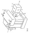
- FIG. 1 schematically shows a partial section through a closure device for the explosive forming 1 in its unspecified position in a press 2.
- the press is here greatly simplified as upper 3 and lower 4 press half shown, in between is an explosive forming tool with a top 5 and a lower box 6.
- a dashed shown reshaped workpiece 36 is still a dashed lines indicated cavity 37 of the tool 5, 6, which determines the final shape, spaced.
- One Also shown in dashed line slightly conical or cylindrical plug 38 widens the workpiece 36 deforming at one end and thus clamps it with respect to the tool 5, 6 a. This plug 38 serves for the tool closure and the sealing of the tool 5, 6.
- An anchor element 7, the closure device 1 is connected to the Explosionsumformwerkmaschinemaschine 5 and 6.
- This anchor element 7 is received in a positive receptacle 8 of a static support structure 9.
- a wedge structure 10 is movably guided, which is actuated by a hydraulic actuator 11.
- the connection unit 14 Via guided in a wedge guide 12 transmission elements 13, the connection unit 14 can be moved with the stopper 38 formed thereon.
- the connection unit 14 is guided axially in the anchor element 7, so that movements can be transmitted only in this direction 28.
- the ratio of the force applied to actuate the wedge structure 10 to the resulting force moving the terminal unit 14 is about 3-5: 1, more preferably 3.5-4.5: 1, and more specifically about 4: 1.
- the wedge guide 12 is inclined about 60 ° to 85 °, in particular 75 ° to 80 ° and in particular about 77 ° relative to the direction of movement 28 of the connection unit 14. This ensures a favorable power ratio to intercept short high force peaks well and so keep the terminal unit 14 during the explosion in the desired position 15. Depending on the inclination of the wedge guide 12 and the inertia of the wedge structure 10 contributes to this task.
- connection unit 14 In a working position 15 of the Anschtussaku 14 is the connection unit 14 on the forming tool 5 and 6 and the plug 38 in the Malawikavtician 37. This is also the hydraulic actuator 11 in its working position 16. Now, the hydraulic actuator 11 in the direction 27 so actuated that it moves from its working position 15 in its rest position shown in dashed lines 17, the wedge structure 10 moves to the same extent with the hydraulic actuator 11 on. The guided in the wedge guide 12 transmission elements 13 of the connection unit 14 are forced to a movement 28 transversely to the mentioned movement 27 of the hydraulic actuator 11 and thus the wedge structure 10. As a result, the connection unit 14 performs an axial movement from its working position 15 to its rest position 18 shown in dashed line, in which it is spaced from the forming tool 5 and 6.
- a gas supply and ignition system 19 is shown with just executed ignition tube and cross-drilled gas supply lines.
- the gas system 19 is supplied via corresponding lines 35 with valves 20.
- the ignition of the gas mixture via an ignition 39th
- connection unit 14 via the work 15, 16 and rest positions 18, 17 of the connection unit 14 and of the actuating wedge structure 10 or of the hydraulic actuator 11 shown in dashed lines is shown.
- FIGS. 2 to 4 show an example of an embodiment of the invention. It puts FIG. 2 the entire closure device 1 in perspective, uncut view.
- the static support structure 9 is executed here in several parts. Between the yoke 21, which is shown here as a top wall of the static support structure 9, and a bottom wall 23 are held by means of fastening elements 25, side walls 24. These side walls 24 enclose the wedge structure 10 approximately annularly and, together with the yoke 21 and the wall 23 shown as a bottom, form the approximately frame-shaped connection unit 14.
- connection unit 14 the gas supply 19 can be seen again. Also here two-piece anchor element 7 can be seen.
- the dotted line 26 shows the axis of the closure device 1 and at the same time the direction of movement of the connection unit 14th
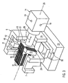
- FIG. 3 shows the closure device 1 from FIG. 2 , wherein the yoke 21, the fasteners 25, one of the side walls 24 of the static support structure 9 and the upper anchor member 7 are not shown, which facilitates a view of the interior.
- the actuator plate 22 can now be seen, to which the hydraulic actuator 11, not shown here, attaches in order to move the wedge structure 10 over it.
- a movement 27 of the wedge structure 10 takes place by the forced coupling a movement 28 of the connection unit 14.
- the forced coupling is performed by guided in the wedge guide 12 transmission elements 13th
- both transmission elements on both sides of metallic sliding linings 29 In order to facilitate the sliding of the wedge guide 12 on the lateral surfaces of the transmission elements 13, both transmission elements on both sides of metallic sliding linings 29.
- the side surfaces of the transmission elements 13 have the same inclination as the wedge guide 12.
- sliding liners 30, which are located on the side of the connection unit 14 facing the yoke can also be found on the sliding surface between the connection unit 14 and the yoke 21.
- sliding linings 31 can be found on the connection unit 14 on the surfaces moving relative to the armature element 7.
- FIG. 3 By drawing omission of the upper anchor element 7 is in FIG. 3 the guide of the connection unit 14 in the anchor element 7 well visible, and the attachment of the anchor element 7 in the positive receptacle 8 of the static support structure 9.
- a passage in the bottom of the wall 23 of the static support structure 9 allows access of the hydraulic actuator 11, not shown via the actuator plate 22 to the wedge structure 10.
- the receptacles 32 of the fasteners 25 of the static support structure 9 can be seen.
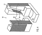
- FIG. 4 shows the wedge structure 10 in detail. Shown is also the actuator plate 22, via which the wedge structure 10 is actuated.
- the metallic sliding linings 33 are located between the wedge structure 10 and the inner sides of the static support structure 9 and allow a low-friction sliding upon actuation of the wedge structure 10.
- additional sliding linings 34 are provided, which are located on the surface of the wedge structure moving with respect to the transfer elements 13 10 and thus form the Gegengleitbeläge to the sliding linings 29 on the transmission elements 13.
- the metallic sliding linings are screwed tight, which are indicated by small black circular areas.
- a workpiece to be reshaped is introduced into the tool 5, 6, which is closed together with the anchoring element 7 divided in two according to upper and lower box 6.
- the anchor element 7 is guided in the aligned in the direction of the closing movement recording 8.
- the connection unit 14 is moved to the tool 5, 6.
- the hydraulic actuator 11 actuates the wedge structure 10 via the actuator plate 22.
- the transmission elements 13 guided in the wedge guide 12 of the wedge structure 10, together with the axial guide, effect the connection unit 14 in the anchor elements 7, a movement of the connection unit to the forming tool 5, 6 to. Due to the inclination of the wedge guide 12 relative to the receptacle 8 of the anchor element 7 and the direction of movement 27 of the wedge structure 10 and the hydraulic actuator 11, this axial displacement of the connection unit 14 in the direction 28 on the tool 5, 6 to.
- an ignitable gas mixture is introduced into the workpiece interior via the gas supply and ignition system 19 and ignited by the ignition 39.
- the high following on the explosion kickback acts counter to the direction of actuation of the connection unit 14, but is supported on the static support structure 9 and about the connection via the anchor member 7 to the forming tool 5, 6 partially redirected such that the forces for sealing closure of Tool 5, 6 can be used by the connection unit 14.
- the connection unit 14 is again moved away from the forming tool 5, 6 into the rest position 18 via reverse movements of the hydraulic actuator 11 and the wedge structure 10.
Landscapes
- Chemical & Material Sciences (AREA)
- Chemical Kinetics & Catalysis (AREA)
- General Chemical & Material Sciences (AREA)
- Physics & Mathematics (AREA)
- Fluid Mechanics (AREA)
- Engineering & Computer Science (AREA)
- Mechanical Engineering (AREA)
- Portable Nailing Machines And Staplers (AREA)
- Clamps And Clips (AREA)
- Mounting, Exchange, And Manufacturing Of Dies (AREA)
- Shaping Metal By Deep-Drawing, Or The Like (AREA)
Description
- Die Erfindung betrifft eine Verschlusseinrichtung für das Explosionsumformen mit den Merkmalen des Oberbegriffs des Anspruchs 1, (siehe Z.B.
EP-A-0 830 907 ). - Beim Explosionsumformen wird ein meist rohrförmiges Werkstück durch den entstehenden Innendruck plastisch aufgeweitet. Vor dem Umformvorgang befindet sich das Werkstück in einem geschlossenen Werkzeug und wird dann durch den Innendruck gegen die Werkzeugkavität gepresst. Der dazu nötige, hohe Innendruck entsteht durch die Zündung eines Gasgemisches im Inneren; bei Detonationsgeschwindigkeiten bis 5000 m/s muss das Werkzeug Kräften äquivalent zu etwa 400 t stand halten. Daher ist das dichtende Schießen des Umformwerkzeugs von besondere Bedeutung für das Explosionsumformen.
- Ein Explosionsumformverfahren ist in der nachveröffentlichten deutschen Patentanmeldung
10 2005 025 660 Vorrichtung und Verfahren zum Explosionsumformen" beschrieben. Die beschriebene Vorrichtung dient insbesondere der Ausbildung einer Dichtung zwischen dem geschlossenen Formwerkzeug und dem rohrartigen Werkstück durch einen konischen Stopfen. Dieser Stopfen bildet die Fortsetzung eines Zündrohrs, welches zwischen einer angerückten Arbeits- und einer zum Formwerkzeug beabstandeten Ruheposition bewegbar ist. Dazu werden die Kraft und der Hub eines Hydraulikzylinders von einem Steuerelement übersetzt. In dem seitlich offenen, vom Hydraulikzylinder betätigten Steuerelement befindet sich eine schräge Nut für das Zündrohr und eine axial verlaufende, gerade Nut für ein Eingriffselement. Über die schräge Nut wird das axial geführte Zündrohr durch eine Bewegung des Steuerelements bewegt. Das Eingriffselement wird von der Bewegung des Steuerelements nicht mit erfasst, da es in der geraden Nut beweglich geführt ist. - Der Erfindung liegt die Aufgabe zu Grunde, eine Verschlusseinrichtung für das Explosionsumformen zu gestalten, mit welcher auf einfache und sichere Art und Weise mit Hilfe einer Bewegung einer Anschlusseinheit ein Explosionsumformwerkzeug verschlossen und die Explosionskräfte abgestützt werden können.
- Diese Aufgabe wird erfindungsgemäß gelöst durch eine Verschlusseinrichtung mit den Merkmalen des Anspruchs 1.
- Die statische Haltestruktur als zusätzliches Element ermöglicht eine Trennung der beiden Funktionen Befestigen der Verschlusseinrichtung am Formwerkzeug und keilübersetzende Bewegungskopplung zwischen der Keilstruktur und der Anschlusseinheit. Die Führung der beweglichen Keilstruktur an der statischen Haltestruktur ermöglicht einen gleichförmigen Bewegungsablauf derselben trotz hoher Betätigungs- und Explosionskräfte. Zudem können diese durch die Umleitung zum Teil quer wirkenden Kräfte seitlich an der statischen Haltestruktur abgestützt werden.
- In einem günstigen Ausführungsbeispiel umfasst die statische Haltestruktur die Keilstruktur rahmenartig. Dies kann bei den auftretenden beträchtlichen Explosionskräften zur Stabilität und Verwindungssteife der Verschlusseinrichtung beitragen und sorgt für eine etwa gleich bleibende Ausrichtung der Bauteile zueinander.
- In einer besonderen Ausführungsform der Erfindung sind an den relativ zueinander bewegten Flächen zwischen der Keilstruktur und der statischen Haltestruktur Gleithilfen vorgesehen. Diese Gleithilfen können eine gleichförmige Bewegung der Keilstruktur an der statischen Haltestruktur unterstützen und die Kraftabstützung über die statische Haltestruktur fördern.
- Vorteilhafterweise sind diese Gleithilfen metallische Gleitbeläge. Metallische Gleitbeläge widerstehen hohen auftretenden Kräften, wie hier bei der Betätigung und infolge der Explosion.
- In einer besonders günstigen Ausführungsform ist die statische Haltestruktur an dem Explosionsumformwerkzeug befestigt. Damit kann die statische Haltestruktur an dem Explosionsumformwerkzeug abgestützt und trotz der auftretenden Schließ- und Explosionskräfte statisch in ihrer Position relativ zum Werkzeug bleiben.
- Es kann von Vorteil sein, die statische Haltestruktur über mindestens ein Ankerelement mit dem Explosionsumformwerkzeug zu verbinden. Damit kann die statische Haltestruktur sicher und wirksam an dem Explosionsumformwerkzeug abgestützt werden.
- In besonderer Weise kann das mindestens eine Ankerelement an der statischen Haltestruktur in mindestens einer formschlüssigen Aufnahme gelagert sein. Über den Formschluss lassen sich die Schließ- und Explosionskräfte sicher übertragen.
- In einer vorteilhaften Ausführungsform ist die Bewegung der Anschlusseinheit an dem Ankerelement geführt. Dies gewährleistet eine sichere Ausrichtung der Bewegung der Anschlusseinheit relativ zu dem Werkzeug und der statischen Haltestruktur.
- Vorteilhafterweise sind an den relativ zueinander bewegten Flächen zwischen der Anschlusseinheit und dem Ankerelement reibungsmindemde Zwischenelemente vorgesehen, um eine gleichmäßige Bewegung der Anschlusseinheit am Ankerelement unterstützen zu können.
- Vorteilhafterweise sind die reibungsmindernden Zwischenelemente metallische Gleitbeläge, welche bei hohen Belastungskräften eine hohe Lebensdauer und einen geringen Verschleiß aufweisen.
- In einer vorteilhaften Ausführungsform umfasst die Keilstruktur die Anschlusseinheit etwa U-förmig quer zur Bewegungsrichtung der Anschlusseinheit. Damit werden die auf die Keilstruktur wirkenden Kräfte gut von ihr aufgenommen, wobei die Bewegung der Anschlusseinheit ermöglicht wird.
- In besonderer Weise weist die Anschlusseinheit mindestens ein mit der Keilstruktur bewegungsgekoppeltes Übertragungselement quer zur Bewegungsrichtung der Anschlusseinheit auf, an welchem die Keilstruktur beweglich ist. An dem Übertragungselement werden die Kräfte und Bewegungen von der Keilstruktur auf die Anschlusseinheit übertragen.
- In einer günstigen Ausführungsform weist die Keilstruktur eine Keilführung auf, mit welcher das mindestens eine Übertragungselement im Eingriff ist. Die Keilführung eignet sich in besonderem Maße, das Übertragungselement darin verkantungssicher zu führen.
- In einer günstigen Ausführungsform der Erfindung sind das mindestens eine Übertragungselement und die mindestens eine Keilführung in gleicher Richtung und in gleichem Maße gegenüber der Bewegungsrichtung der Anschlusseinheit geneigt. Das kann die Übertragung von Kräften und Hüben verbessern und gleichförmige Bewegungen des Übertragungselements in der Keilführung ermöglichen.
- Vorteilhafterweise sind an den relativ zueinander bewegten Flächen zwischen dem mindestens einen Übertragungselement und der mindestens einen Keilführung gleitfördemde Zwischenstrukturen vorgesehen. Dies ermöglicht eine wirksamere Kraftübertragung zwischen dem Übertragungselement und der Keilaufnahme.
- In einem günstigen Ausführungsbeispiel sind die gleitfördemden Zwischenstrukturen metallische Gleitbeläge. Metallische Gleitbeläge überzeugen bei hohen Kräften durch generelle Abriebarmut.
- Vorteilhafterweise wird die Keilstruktur mit Hilfe eines Betätigungselements, insbesondere eines Hydraulik-Aktuators bewegt. Das Betätigungselement kann den Anforderungen bezüglich Kraft und Hub entsprechend ausgewählt werden. Hydraulik-Aktuatoren eignen sich aufgrund der hohen erzielbaren Kräfte verbunden mit ausreichender Präzision.
- Es kann von Vorteil sein, dass sich das Betätigungselement quer durch die Wandung der statischen Haltestruktur erstreckt. "Wandung" in diesem Sinne beinhaltet Seiten-, Decken- und/oder Bodenwände. Damit ist ein guter Zugang des Betätigungselements zu der Keilstruktur in der Verschlusseinrichtung gewährleistet.
- In einer besonderen Ausführungsform der Erfindung ist die Verschlusseinrichtung als Einheit lösbar am Explosionsumformwerkzeug befestigt. Damit kann die Verschlusseinrichtung je nach Verwendung an ein gewünschtes Werkzeug angebracht und später gegebenenfalls an ein anderes Werkzeug für eine neue Verwendung angebracht werden.
- Günstigerweise weist die statische Haltestruktur eine etwa ringartig geschlossene Struktur auf. Derart geschlossene Strukturen können äußerst stabil und verwindungssteif sein, was bei den beim Explosionsumformen auftretenden Kräften von großem Vorteil sein kann.
- In einer Ausführungsform ist die statische Haltestruktur durch ein Joch etwa ringartig geschlossen. Das Joch schließt die Haltestruktur in versteifender Weise und kann bei der Montage und Demontage für eine gute Zugänglichkeit der in der statischen Haltestruktur befindlichen Teile sorgen. Auch bei der Fertigung kann die erwähnte Mehrteiligkeit in Bezug auf Fertigungsaufwand und Kosten von Vorteil sein.
- Es ist von Vorteil, wenn die Anschlusseinheit an dem Joch gleitgeführt abgestützt ist. Diese zusätzliche Führung kann eine gleichmäßige Bewegung der Anschlusseinheit unterstützen und zur Verwindungssteifigkeit der Gesamteinrichtung beitragen.
- Vorteilhafterweise weist mindestens eine der relativ zueinander bewegten Flächen zwischen der Anschlusseinheit und dem Joch mindestens ein Gleitelement auf. Diese zusätzlichen Elemente können neben der Reibungsminderung auch den Vorteil besitzen, dass sich Fertigungstoleranzen ausgleichen lassen.
- Günstigerweise weisen die Gleitelemente metallische Gleitbeläge auf. Besonders metallische Gleitbeläge lassen sich mit sehr engen Toleranzen fertigen.
- In einem günstigen Ausführungsbeispiel der Erfindung weist die Anschlusseinheit zwei Übertragungselemente und die Keilstruktur zwei Keilführungen jeweils quer zur Bewegungsrichtung der Anschlusseinheit auf. Das Vorhandensein je zweier Elemente im Eingriff kann dafür sorgen, dass der Kraftfluss aufgeteilt und besser abgestützt wird.
- In einer vorteilhaften Ausführungsform weist die Anschlusseinheit mindestens eine Gaszufuhreinheit und/oder eine Zündvorrichtung und/oder einen Werkzeugverschluss und/oder eine Werkzeugabdichtung auf.
- Im Folgenden wird ein Ausführungsbeispiel der Erfindung anhand der Zeichnung beschrieben. Es zeigen:
- Figur 1
- schematisch das Prinzip der Erfindung mit einem Teilschnitt durch die Verschlusseinrichtung,
- Figur 2
- eine Ausführungsform der Verschlusseinrichtung in perspektivischer Ansicht,
- Figur 3
- einen Teil der Verschlusseinrichtung aus
Figur 2 und - Figur 4
- die Keilstruktur der Verschlusseinrichtung von
Figur 2 im Detail. - Gleiche Bezugszeichen verweisen dabei auf gleiche Teile bzw. Merkmale, unabhängig von der Figur, in welcher sie dargestellt werden.
-
Figur 1 zeigt schematisch einen Teilschnitt durch eine Verschlusseinrichtung für das Explosionsumformen 1 in ihrer nicht näher detaillierten Lage in einer Presse 2. Die Presse ist hier stark vereinfacht als obere 3 und untere 4 Pressenhälfte dargestellt, dazwischen befindet sich ein Explosionsumformwerkzeug mit einem Ober- 5 und einem Unterkasten 6. Ein gestrichelt dargestelltes umzuformendes Werkstück 36 ist noch von einer gestrichelt angedeuteten Kavität 37 des Werkzeugs 5, 6, die dessen Endgestalt bestimmt, beabstandet. Ein ebenfalls in gestrichelter Linie gezeigter leicht konischer oder zylindrischer Stopfen 38 weitet das Werkstück 36 an einem Ende verformend auf und spannt es damit gegenüber dem Werkzeug 5, 6 ein. Dieser Stopfen 38 dient dem Werkzeugverschluss und der Abdichtung des Werkzeugs 5, 6. - Über ein Ankerelement 7 ist die Verschlusseinrichtung 1 mit dem Explosionsumformwerkzeug 5 und 6 verbunden. Dieses Ankerelement 7 ist in einer formschlüssigen Aufnahme 8 einer statischen Haltestruktur 9 aufgenommen. In der statischen Haltestruktur 9 ist eine Keilstruktur 10 beweglich geführt, welche von einem Hydraulik-Aktuator 11 betätigt wird. Über in einer Keilführung 12 geführte Übertragungselemente 13 kann die Anschlusseinheit 14 mit dem daran ausgebildeten Stopfen 38 bewegt werden. Die Anschlusseinheit 14 ist in dem Ankerelement 7 axial geführt, so dass Bewegungen nur in dieser Richtung 28 übertragen werden können.
- Das Verhältnis der zur Betätigung der Keilstruktur 10 aufzubringenden Kraft zu der resultierenden, die Anschlusseinheit 14 bewegenden Kraft ist etwa 3-5:1, insbesondere 3,5-4,5:1 und im Besonderen etwa 4:1. Dazu ist die Keilführung 12 etwa 60° bis 85°, insbesondere 75° bis 80° und im Besonderen etwa 77° gegenüber der Bewegungsrichtung 28 der Anschlusseinheit 14 geneigt. Dies gewährleistet ein günstiges Kraftverhältnis, um kurzzeitige hohe Kraftspitzen gut abzufangen und so die Anschlusseinheit 14 auch während der Explosion in der gewünschten Position 15 zu halten. Je nach Neigung der Keilführung 12 trägt auch die Trägheit der Keilstruktur 10 mit zu dieser Aufgabe bei.
- In einer Arbeitsposition 15 der Anschtusseinheit 14 befindet sich die Anschlusseinheit 14 am Umformwerkzeug 5 und 6 und der Stopfen 38 in der Werkzeugkavität 37. Dabei befindet sich auch der Hydraulik-Aktuator 11 in seiner Arbeitsposition 16. Wird nun der Hydraulik-Aktuator 11 in der Richtung 27 derart betätigt, dass er sich von seiner Arbeitsposition 15 in seine gestrichelt dargestellte Ruheposition 17 bewegt, bewegt sich die Keilstruktur 10 in gleichem Maße mit dem Hydraulik-Aktuator 11 fort. Die in der Keilführung 12 geführten Übertragungselemente 13 der Anschlusseinheit 14 werden zu einer Bewegung 28 quer zur erwähnten Bewegung 27 des Hydraulik-Aktuators 11 und damit der Keilstruktur 10 gezwungen. Dadurch führt die Anschlusseinheit 14 eine axiale Bewegung von ihrer Arbeitsposition 15 in ihre in gestrichelter Linie gezeigte Ruheposition 18 aus, in der sie zum Umformwerkzeug 5 und 6 beabstandet ist.
- Im Schnitt der Anschlusseinheit 14 ist ein Gaszufuhr- und -zündsystem 19 mit gerade ausgeführtem Zündrohr und quergebohrten Gaszuleitungen gezeigt. Versorgt wird das Gassystem 19 über entsprechende Leitungen 35 mit Ventilen 20. Die Zündung des Gasgemisches erfolgt über eine Zündeinrichtung 39.
- Aus der Schemadarstellung in
Figur 1 ist speziell die Bewegungskopplung der Anschlusseinheit 14 über die in gestrichelter Linie dargestellten Arbeits- 15, 16 und Ruhepositionen 18, 17 der Anschlusseinheit 14 sowie der betätigenden Keilstruktur 10 bzw. des Hydraulik-Aktuators 11 dargestellt. - Eine Ausgestaltung der einzelnen Komponenten der Verschlusseinrichtung 1, speziell der Übertragungselemente 13, wird aus den folgenden
Figuren 2 bis 4 detailliert ersichtlich. - Ebenso sind z.B. ein Joch 21 und eine Aktuatorplatte 22 der Einfachheit halber erst in den folgenden Figuren dargestellt, dafür wird auf den Stopfen 38 nicht näher eingegangen.
- Die
Figuren 2 bis 4 zeigen exemplarisch eine Ausführungsform der Erfindung. Dabei stelltFigur 2 die gesamte Verschlusseinrichtung 1 in perspektivischer, ungeschnittener Ansicht dar. Die statische Haltestruktur 9 ist hier mehrteilig ausgeführt. Zwischen dem Joch 21, welches hier als Deckenwandung der statischen Haltestruktur 9 dargestellt ist, und einer Bodenwandung 23 werden mit Hilfe von Befestigungselementen 25, Seitenwandungen 24 gehalten. Diese Seitenwandungen 24 umschließen die Keilstruktur 10 etwa ringförmig und bilden zusammen mit dem Joch 21 und der als Boden dargestellten Wandung 23 die etwa rahmenförmige Anschlusseinheit 14. - An der Anschlusseinheit 14 ist wieder die Gaszufuhr 19 erkennbar. Auch das hier zweiteilig ausgebildete Ankerelement 7 ist zu sehen. Die strichpunktierte Linie 26 zeigt die Achse der Verschlusseinrichtung 1 und gleichzeitig die Bewegungsrichtung der Anschlusseinheit 14.
-
Figur 3 zeigt die Verschlusseinrichtung 1 ausFigur 2 , wobei das Joch 21, die Befestigungselemente 25, eine der Seitenwandungen 24 der statischen Haltestruktur 9 und das obere Ankerelement 7 nicht dargestellt sind, was einen Blick auf das Innenleben erleichtert. So ist jetzt die Aktuatorplatte 22 zu sehen, an welcher der hier nicht gezeigte Hydraulik-Aktuator 11 ansetzt, um über sie die Keilstruktur 10 zu bewegen. Durch eine Bewegung 27 der Keilstruktur 10 erfolgt durch die Zwangskopplung eine Bewegung 28 der Anschlusseinheit 14. Die Zwangskopplung erfolgt durch in der Keilführung 12 geführte Übertragungselemente 13. - Um das Gleiten der Keilführung 12 an den seitlichen Flächen der Übertragungselemente 13 zu erleichtern, weisen beide Übertragungselemente beidseits metallische Gleitbeläge 29 auf. Im Übrigen weisen die Seitenflächen der Übertragungselemente 13 die selbe Neigung wie die Keilführung 12 auf. Zur Reibungsminderung finden sich auch an der Gleitfläche zwischen der Anschlusseinheit 14 und dem Joch 21 Gleitbeläge 30, welche sich an der dem Joch zugewandten Seite der Anschlusseinheit 14 befinden. Weitere, ebenfalls metallische, Gleitbeläge 31 finden sich an der Anschlusseinheit 14 an den relativ gegenüber dem Ankerelement 7 bewegten Flächen.
- Durch zeichnerisches Weglassen des oberen Ankerelements 7 ist in
Figur 3 die Führung der Anschlusseinheit 14 im Ankerelement 7 gut ersichtlich, sowie die Befestigung des Ankerelements 7 in der formschlüssigen Aufnahme 8 der statischen Haltestruktur 9. Ein Durchgang in der als Boden ausgeprägten Wandung 23 der statischen Haltestruktur 9 erlaubt einen Zugang des nicht dargestellten Hydraulik-Aktuators 11 über die Aktuatorplatte 22 zur Keilstruktur 10. In der Bodenwandung 23 sind ebenfalls die Aufnahmen 32 der Befestigungselemente 25 der statischen Haltestruktur 9 zu sehen. -
Figur 4 zeigt die Keilstruktur 10 im Detail. Dargestellt ist ebenfalls die Aktuatorplatte 22, über welche die Keilstruktur 10 betätigt wird. Zu sehen ist hier eine zweigeteilte Keilstruktur 10 sowie deren Gleitbeläge. Die metallischen Gleitbeläge 33 befinden sich zwischen der Keilstruktur 10 und den Innenseiten der statischen Haltestruktur 9 und ermöglichen dort ein reibungsarmes Abgleiten bei Betätigung der Keilstruktur 10. In dieser Ausführungsform sind zusätzliche Gleitbeläge 34 vorgesehen, die sich an der gegenüber den Übertragungselementen 13 bewegten Fläche der Keilstruktur 10 befinden und die somit die Gegengleitbeläge zu den Gleitbelägen 29 an den Übertragungselementen 13 bilden. Wie in der Figur vorher sind in dieser Ausführungsform die metallischen Gleitbeläge festgeschraubt, welche durch kleine schwarze Kreisflächen kenntlich gemacht sind. - Ein umzuformendes Werkstück wird in das Werkzeug 5, 6 eingebracht, welches zusammen mit dem entsprechend Ober- 5 und Unterkasten 6 zweigeteilten Ankerelement 7 geschlossen wird. Dabei wird das Ankerelement 7 in der in Richtung der Schließbewegung ausgerichteten Aufnahme 8 geführt. Zum Explosionsumformen des Werkstücks wird die Anschlusseinheit 14 zum Werkzeug 5, 6 bewegt. Dazu betätigt der Hydraulik-Aktuator 11 über die Aktuatorplatte 22 die Keilstruktur 10. Die in der Keilführung 12 der Keilstruktur 10 geführten Übertragungselemente 13 bewirken zusammen mit der Axialführung der Anschlusseinheit 14 in den Ankerelementen 7 eine Bewegung der Anschlusseinheit auf das Umformwerkzeug 5, 6 zu. Durch die Neigung der Keilführung 12 gegenüber der Aufnahme 8 des Ankerelements 7 und der Bewegungsrichtung 27 der Keilstruktur 10 und des Hydraulik-Aktuators 11 kommt es zu diesem Axialversatz der Anschlusseinheit 14 in Richtung 28 auf das Werkzeug 5, 6 zu.
- Durch die Gasleitungen 35 und Ventile 20 wird ein zündfähiges Gasgemisch über das Gaszufuhr- und -zündsystem 19 in das Werkstückinnere eingebracht und durch die Zündung 39 gezündet. Der hohe auf die Explosion folgende Rückschlag wirkt entgegen der Betätigungsrichtung auf die Anschlusseinheit 14, wird jedoch über die statische Haltestruktur 9 abgestützt und über deren Anbindung über das Ankerelement 7 an das Umformwerkzeug 5, 6 zum Teil derart umgeleitet, dass die Kräfte zum dichtenden Verschluss des Werkzeugs 5, 6 durch die Anschlusseinheit 14 eingesetzt werden können. Nach erfolgtem Umformen wird die Anschlusseinheit 14 über umgekehrte Bewegungen des Hydraulik-Aktuators 11 und der Keilstruktur 10 wieder vom Umformwerkzeug 5, 6 in die Ruheposition 18 abgerückt.
Claims (15)
- Verschlusseinrichtung (1) für das Explosionsumformen, mit welcher eine Anschlusseinheit (14) gegenüber einem Explosionsumformwerkzeug (5, 6) zwischen einer Arbeitsposition (15) an dem Werkzeug (5, 6) und einer Ruheposition (18) bewegbar ist, dadurch gekennzeichnet, dass eine Keilstruktur (10) beweglich an einer statischen Haltestruktur (9) geführt und mit der Anschlusseinheit (14) bewegungsgekoppelt ist, wobei eine Bewegung (28) der Anschlusseinheit (14) quer zu einer Bewegung (27) der Keilstruktur (10) gerichtet ist.
- Einrichtung (1) nach Anspruch 1,
dadurch gekennzeichnet,
dass die statische Haltestruktur (9) die Keilstruktur (10) rahmenartig umfasst. - Einrichtung (1) nach Anspruch 1 oder 2,
dadurch gekennzeichnet,
dass an den relativ zueinander bewegten Flächen zwischen der Keilstruktur (10) und der statischen Haltestruktur (9) Gleithilfen vorgesehen sind. - Einrichtung (1) nach mindestens einem der vorhergehenden Ansprüche,
dadurch gekennzeichnet,
dass die statische Haltestruktur (9) an dem Explosionsumformwerkzeug (5, 6) befestigt ist. - Einrichtung (1) nach Anspruch 4,
dadurch gekennzeichnet,
dass die statische Haltestruktur (9) über mindestens ein Ankerelement (7) mit dem Explosionsumformwerkzeug (5, 6) verbunden ist. - Einrichtung (1) nach Anspruch 5,
dadurch gekennzeichnet,
dass das mindestens eine Ankerelement (7) an der statischen Haltestruktur (9) in mindestens einer formschlüssigen Aufnahme (8) gelagert ist. - Einrichtung (1) nach Anspruch 5 oder 6,
dadurch gekennzeichnet,
dass die Bewegung (28) der Anschlusseinheit (14) an dem Ankerelement (7) geführt ist. - Einrichtung (1) nach mindestens einem der vorhergehenden Ansprüche,
dadurch gekennzeichnet,
dass die Keilstruktur (10) die Anschlusseinheit (14) quer zur Bewegungsrichtung (28) der Anschlusseinheit (14) etwa U-förmig umfasst. - Einrichtung (1) nach mindestens einem der vorhergehenden Ansprüche,
dadurch gekennzeichnet,
dass die Anschlusseinheit (14) mindestens ein mit der Keilstruktur (10) bewegungsgekoppeltes Übertragungselement (13) quer zur Bewegungsrichtung (28) der Anschlusseinheit (14) aufweist, an welchem die Keilstruktur (10) beweglich ist. - Einrichtung (1) nach Anspruch 9,
dadurch gekennzeichnet,
dass die Keilstruktur (10) mindestens eine Keilführung (12) aufweist, mit welcher das mindestens eine Übertragungselement (13) in Eingriff ist. - Einrichtung (1) nach Anspruch 10,
dadurch gekennzeichnet,
dass das mindestens eine Übertragungselement (13) und die mindestens eine Keilführung (12) in gleicher Richtung und in gleichem Maße gegenüber der Bewegungsrichtung (28) der Anschlusseinheit (14) geneigt sind. - Einrichtung (1) nach mindestens einem der vorhergehenden Ansprüche,
dadurch gekennzeichnet,
dass die Keilstruktur (10) mit Hilfe eines Betätigungselements, insbesondere eines Hydraulik-Aktuators, bewegt wird. - Einrichtung (1) nach Anspruch 12,
dadurch gekennzeichnet,
dass sich das Betätigungselement quer durch die Wandung (23) der statischen Haltestruktur (9) erstreckt. - Einrichtung (1) nach mindestens einem der vorhergehenden Ansprüche,
dadurch gekennzeichnet,
dass diese als Einheit lösbar am Explosionsumformwerkzeug (5, 6) befestigt ist. - Einrichtung (1) nach mindestens einem der vorhergehenden Ansprüche,
dadurch gekennzeichnet,
dass die statische Haltestruktur (9) eine etwa ringartig geschlossene Struktur aufweist.
Applications Claiming Priority (2)
| Application Number | Priority Date | Filing Date | Title |
|---|---|---|---|
| DE102006056788A DE102006056788B4 (de) | 2006-12-01 | 2006-12-01 | Verschlusseinrichtung für das Explosionsumformen |
| PCT/EP2007/009113 WO2008064746A1 (de) | 2006-12-01 | 2007-10-19 | Verschlusseinrichtung für das explosionsumformen |
Publications (2)
| Publication Number | Publication Date |
|---|---|
| EP2097188A1 EP2097188A1 (de) | 2009-09-09 |
| EP2097188B1 true EP2097188B1 (de) | 2012-10-17 |
Family
ID=38698391
Family Applications (1)
| Application Number | Title | Priority Date | Filing Date |
|---|---|---|---|
| EP07819178A Not-in-force EP2097188B1 (de) | 2006-12-01 | 2007-10-19 | Verschlusseinrichtung für das explosionsumformen |
Country Status (4)
| Country | Link |
|---|---|
| US (1) | US8250892B2 (de) |
| EP (1) | EP2097188B1 (de) |
| DE (1) | DE102006056788B4 (de) |
| WO (1) | WO2008064746A1 (de) |
Families Citing this family (9)
| Publication number | Priority date | Publication date | Assignee | Title |
|---|---|---|---|---|
| DE102005025660B4 (de) | 2005-06-03 | 2015-10-15 | Cosma Engineering Europe Ag | Vorrichtung und Verfahren zum Explosionsumformen |
| DE102006037754B3 (de) | 2006-08-11 | 2008-01-24 | Cosma Engineering Europe Ag | Verfahren und Vorrichtung zum Explosionsumformen |
| DE102006037742B4 (de) | 2006-08-11 | 2010-12-09 | Cosma Engineering Europe Ag | Verfahren und Vorrichtung zum Explosionsumformen |
| DE102006056788B4 (de) | 2006-12-01 | 2013-10-10 | Cosma Engineering Europe Ag | Verschlusseinrichtung für das Explosionsumformen |
| DE102006060372A1 (de) | 2006-12-20 | 2008-06-26 | Cosma Engineering Europe Ag | Werkstück und Verfahren für das Explosionsumformen |
| DE102007007330A1 (de) | 2007-02-14 | 2008-08-21 | Cosma Engineering Europe Ag | Verfahren und Werkzeuganordnung zum Explosionsumformen |
| DE102007036196A1 (de) | 2007-08-02 | 2009-02-05 | Cosma Engineering Europe Ag | Vorrichtung für die Zufuhr eines Fluids für Explosionsumformen |
| US9636736B2 (en) * | 2007-12-13 | 2017-05-02 | Cosma Engineering Europe Ag | Method and mould arrangement for explosion forming |
| DE102008006979A1 (de) | 2008-01-31 | 2009-08-06 | Cosma Engineering Europe Ag | Vorrichtung für das Explosionsumformen |
Family Cites Families (103)
| Publication number | Priority date | Publication date | Assignee | Title |
|---|---|---|---|---|
| DE1452667U (de) | ||||
| US392635A (en) | 1888-11-13 | powers | ||
| US1280451A (en) | 1917-02-02 | 1918-10-01 | William F Hagen | Valve. |
| GB742460A (en) | 1952-06-11 | 1955-12-30 | Union Carbide & Carbon Corp | Sheet metal forming by use of detonation waves |
| GB878178A (en) | 1959-12-01 | 1961-09-27 | Olin Mathieson | Metal forming |
| DE1129562B (de) | 1961-04-21 | 1962-05-17 | Telefonbau | Schaltungsanordnung zur Gebuehrenerfassung mit Gespraechszetteldrucker im internationalen Fernwahlbetrieb |
| US3252312A (en) * | 1962-04-25 | 1966-05-24 | Continental Can Co | Method and apparatus for explosive reshaping of hollow ductile objects |
| US3160949A (en) * | 1962-05-21 | 1964-12-15 | Aerojet General Co | Method of joining elongated objects |
| DE1235246B (de) | 1962-07-17 | 1967-03-02 | Wmf Wuerttemberg Metallwaren | Vorrichtung zur Hochenergieformung, insbesondere zur Explosionsumformung von Metallblechen od. dgl. |
| CH409831A (de) | 1962-08-28 | 1966-03-31 | Josef Schaberger & Co G M B H | Vorrichtung zur Verformung von Körpern durch Explosion |
| FR1342377A (fr) | 1962-10-17 | 1963-11-08 | Continental Can Co | Procédé et dispositif de refaçonnage par explosion d'objets creux ductiles |
| DE1218986B (de) | 1962-12-21 | 1966-06-16 | Wmf Wuerttemberg Metallwaren | Verfahen und Platine zur Herstellung von Hohlkoerpern oder aehnlichen Formteilen ausBlech durch Hochenergieumformung |
| AT248838B (de) | 1963-11-19 | 1966-08-25 | Wmf Wuerttemberg Metallwaren | Verfahren und Werkzeug zur Herstellung von Werkstücken durch Hochenergieformung |
| US3342048A (en) * | 1964-08-13 | 1967-09-19 | Gen Am Transport | Detonation wave forming machine |
| US3338080A (en) | 1964-09-21 | 1967-08-29 | Gen Dynamics Corp | Forming apparatus |
| DE1527949A1 (de) | 1965-01-19 | 1969-11-20 | Chemokomplex Vegyipari Gep Es | Verfahren und Einrichtung zur Ausbildung von gewoelbten Schalen aus Metallplatten |
| DE1452667A1 (de) | 1965-09-30 | 1969-03-06 | Gen American Transp Corp | Maschine zum plastischen Verformen mittels Detonationswellen |
| GB1129562A (en) | 1966-03-07 | 1968-10-09 | Vickers Ltd | The generation of shock waves by exploding wire methods |
| GB1280451A (en) * | 1968-05-02 | 1972-07-05 | Int Research & Dev Co Ltd | Improvements in and relating to methods of explosively welding tubes into tube plates |
| AT299664B (de) * | 1968-05-17 | 1972-06-26 | Boehler & Co Ag Geb | Vorrichtung zur Explosionverformung metallischer Werkstoffe |
| DE1777207A1 (de) | 1968-09-25 | 1971-04-01 | Hertel Heinrich Prof Dr Ing | Vorrichtung zur Hochleistungsumformung von Werkstuecken,insbesondere aus Blech,mit Hilfe von Schockwirkungsmitteln |
| DE1777208A1 (de) | 1968-09-25 | 1971-04-01 | Hertel Heinrich Prof Dr Ing | Vorrichtung zur Hochleistungsumformung von Werkstuecken,insbesondere aus Blech,mit Hilfe von Schockwirkungsmitteln |
| DE1801784A1 (de) | 1968-10-08 | 1970-06-11 | Bbc Brown Boveri & Cie | Arbeitsfunkenstrecke zur Erzeugung von Druckwellen in einem isolierenden,fluessigen Medium |
| DE1808942A1 (de) | 1968-11-14 | 1970-06-11 | Rune Hank | Verfahren zur Explosionsumformung |
| US3654788A (en) * | 1968-11-20 | 1972-04-11 | Lead Metal Kogyo Kk | Method of discharge forming bulged articles |
| US3640110A (en) * | 1969-08-14 | 1972-02-08 | Inoue K | Shock forming |
| US3661004A (en) * | 1969-11-07 | 1972-05-09 | Atlas Chem Ind | Explosive tubing swager |
| US3737975A (en) * | 1970-07-15 | 1973-06-12 | Kinnon C Mc | Arrangement for explosively formed connections and method of making such connections |
| DE2043251A1 (en) | 1970-09-01 | 1972-03-02 | Nydamit Nobel Ag | Explosive forming - by shock wave conducted into the workpiece from outside |
| DE2059181C3 (de) | 1970-12-02 | 1975-02-27 | Messwandler-Bau Gmbh, 8600 Bamberg | Anordnung zur Hochdruck-Energieumformung von Körpern |
| US3742746A (en) * | 1971-01-04 | 1973-07-03 | Continental Can Co | Electrohydraulic plus fuel detonation explosive forming |
| DE2107460A1 (en) | 1971-02-17 | 1972-08-31 | Mylaeus Geb | Internally expanding pipes - to centrally increase their buckling strength |
| GB1436538A (en) | 1972-11-17 | 1976-05-19 | Dale Ltd John | Manufacture of articles such as collapsible tubes |
| DE2337176C3 (de) | 1973-07-21 | 1981-08-06 | Tokyu Sharyo Seizo K.K., Yokohama, Kanagawa | Vorrichtung zum Hochgeschwindigkeitsumformen vom metallischen rohrförmigen Werkstücken in einer mehrteiligen Formkammer |
| GB1419889A (en) | 1973-12-21 | 1975-12-31 | Kh Aviatsionnyj Institut | Plant for explosive forming |
| ZA754574B (en) | 1974-07-29 | 1976-06-30 | Concast Inc | A method of forming the walls of continuous casting and chill |
| DD114231A1 (de) | 1974-08-29 | 1975-07-20 | ||
| FR2300322A1 (fr) | 1975-02-04 | 1976-09-03 | Poudres & Explosifs Ste Nale | Systeme de mise a feu pour charges explosives immergees |
| SU575161A1 (ru) | 1975-05-11 | 1977-10-05 | Физико-технический институт АН Белорусской ССР | Устройство дл штамповки листовых заготовок жидкостью высокого давлени |
| GB1482978A (en) | 1975-06-27 | 1977-08-17 | Ici Ltd | Expanding metal tubes |
| DE2628579C2 (de) | 1976-06-25 | 1983-02-17 | Fiziko-techničeskij institut Akademii Nauk Belorusskoj SSR, Minsk | Vorrichtung zum elektrohydraulischen Explosionsumformen |
| GB1542519A (en) | 1976-07-07 | 1979-03-21 | Fiz Tekh I An Brus Ssr | Electrical discharge forming devices |
| US4187709A (en) * | 1976-08-23 | 1980-02-12 | Kevin Strickland | Explosive forming |
| DE2754666A1 (de) | 1977-12-08 | 1979-06-13 | Hinapat Ag | Verfahren und vorrichtung zur herstellung eines tubenrohlings |
| DD135859A1 (de) | 1978-04-24 | 1979-06-06 | Heinz Heinrich | Verfahren zum zuenden von sprengstoff in explosivumformanlagen |
| GB2047147B (en) | 1979-04-06 | 1982-12-08 | Ukrain Nii Protezirova Protez | Manufacturing sockets for extremity prosthesis |
| DE3012342C2 (de) | 1980-03-29 | 1984-08-16 | Scheuch Folien- und Papierverarbeitung GmbH & Co KG, 6109 Mühltal | Mehrschichtfolie und Verfahren zum Verschluß von Gefäßen |
| AT371384B (de) | 1980-08-08 | 1983-06-27 | Uk Nii Protezirovania Protezos | Verfahren zum umformen eines werkstueckes durch impulsbelastung, gaskanone zur durchfuehrung des verfahrens sowie umformeinrichtung zum umformen von werkstuecken durch impulsbelastung mit einer solchen gaskanone |
| DD158364B1 (de) | 1981-04-09 | 1986-03-12 | Germania Chemnitz | Schutzvorrichtung zur explosivbearbeitung von bauteilen |
| BG34210A1 (en) * | 1981-07-15 | 1983-08-15 | Kortenski | Machine for explosive forming |
| US4492104A (en) * | 1981-12-02 | 1985-01-08 | Meadowcraft Inc. | Explosive shaping of metal tubing |
| JPS58145381A (ja) | 1982-02-23 | 1983-08-30 | Mitsubishi Heavy Ind Ltd | クラツド鋼管の製造方法 |
| US4494392A (en) | 1982-11-19 | 1985-01-22 | Foster Wheeler Energy Corporation | Apparatus for forming an explosively expanded tube-tube sheet joint including a low energy transfer cord and booster |
| DE3305615C2 (de) | 1983-02-18 | 1986-10-16 | Heinrich Dr.-Ing. 4290 Bocholt Hampel | Anordnung zum Befestigen eines Rohres in einer Lochplatte mittels Explosionsdruckwellen |
| US4571800A (en) * | 1983-07-11 | 1986-02-25 | Thiokol Corporation | Method for explosively forming an auxiliary exit cone for the nozzle of a rocket motor |
| DD217154A1 (de) | 1983-09-06 | 1985-01-09 | Komb Pumpen U Verdichter Wtz V | Verfahren und vorrichtung zum warmexplosivumformen von blechhohlteilen |
| DE3347319A1 (de) | 1983-12-28 | 1985-07-11 | Kraftwerk Union AG, 4330 Mülheim | Einrichtung zum schweissplattieren von rohren |
| DE3581293D1 (de) | 1984-02-09 | 1991-02-21 | Toyota Motor Co Ltd | Verfahren zur herstellung von ultrafeinen keramikpartikeln. |
| SU1181331A1 (ru) | 1984-06-05 | 1989-10-23 | Научно-исследовательский институт технологии автомобильной промышленности | Установка дл детонационного напылени |
| DE3512015A1 (de) | 1985-04-02 | 1986-10-02 | Robert Bosch Gmbh, 7000 Stuttgart | Vorrichtung zur behandlung von werkstuecken mittels temperatur- und druckstoessen durch zuenden eines brennbaren gasgemisches, insbesondere thermische entgratanlage |
| US4738012A (en) * | 1985-12-31 | 1988-04-19 | Hughes Robert W | Method of making a cam shaft |
| DE3709181A1 (de) | 1987-03-20 | 1988-09-29 | Asea Ab | Verfahren zur herstellung von komplizierten blechteilen und werkzeug fuer die druckumformung solcher blechteile |
| DD260450A1 (de) | 1987-04-09 | 1988-09-28 | Pk Byuro Elektrogidravliki An | Verfahren und vorrichtung zum einpressen von rohren durch elektrische zuendung |
| US4856311A (en) * | 1987-06-11 | 1989-08-15 | Vital Force, Inc. | Apparatus and method for the rapid attainment of high hydrostatic pressures and concurrent delivery to a workpiece |
| US4788841A (en) * | 1987-11-18 | 1988-12-06 | Aluminum Company Of America | Method and apparatus for making step wall tubing |
| JPH02117728A (ja) | 1988-10-25 | 1990-05-02 | Sumitomo Metal Ind Ltd | 外面2条ひれ付管の製造装置 |
| GB8918552D0 (en) * | 1989-08-15 | 1989-09-27 | Alford Sidney C | Flexible linear explosive cutting or fracturing charge |
| DE4035894C1 (en) | 1990-11-12 | 1992-01-30 | Hampel, Heinrich, Dr., Moresnet, Be | Cooling box for blast furnaces with low mfr. cost - produced from cooling pipe preformed with number bends and explosively welded |
| US5256430A (en) * | 1991-05-29 | 1993-10-26 | Nkk Corporation | Method for generating a detonation pressure |
| GB9114444D0 (en) * | 1991-07-04 | 1991-08-21 | Cmb Foodcan Plc | Apparatus and method for reshaping containers |
| US5220727A (en) * | 1992-06-25 | 1993-06-22 | Hochstein Peter A | Method making cam shafts |
| DE4232913C2 (de) | 1992-10-01 | 1995-04-27 | Daimler Benz Ag | Zweistufiges Verfahren zum hydromechanischen explosionsunterstützen Tiefziehen von Blech und Tiefziehpresse zur Durchführung des Verfahrens |
| DE19536292C2 (de) | 1995-09-29 | 1997-09-25 | Leinemann Gmbh & Co | Verfahren und Vorrichtung zum Abschwächen einer Detonation in einem Behälter- bzw. Rohrleitungssystem |
| DE19638688A1 (de) | 1996-09-20 | 1998-03-26 | Schmalbach Lubeca | Verschlußvorrichtung für Einrichtung zum Expansionsformen mit konischem Stopfen |
| EP0830907A3 (de) | 1996-09-20 | 1998-09-23 | Schmalbach-Lubeca AG | Verschlussvorrichtung für eine Einrichtung zum Expansionsformen |
| DE19638679A1 (de) | 1996-09-20 | 1998-03-26 | Schmalbach Lubeca | Verschlußvorrichtung für Einrichtung zum Expansionsformen mit lanzenförmigem Stopfen |
| DE19638678A1 (de) * | 1996-09-20 | 1998-03-26 | Schmalbach Lubeca | Verschlußvorrichtung für eine Einrichtung zum Expansionsformen |
| DE19709918C2 (de) | 1997-03-11 | 2001-02-01 | Dornier Medizintechnik | Hochleistungs-Druckwellenquelle |
| US5890698A (en) * | 1997-10-13 | 1999-04-06 | Domytrak; Walter | Valve having pressure equalizing conduit |
| IL122795A (en) | 1997-12-29 | 2002-02-10 | Pulsar Welding Ltd | Combined pulsed magnetic and pulsed discharge forming of a dish from a planar plate |
| DE19818572C1 (de) | 1998-04-25 | 1999-11-11 | Leinemann Gmbh & Co | Verfahren zum Unschädlichmachen einer Detonationsfront und Detonationssicherung |
| SE518722C2 (sv) | 1998-06-26 | 2002-11-12 | Flow Holdings Gmbh Sagl Llc | Anordning och förfarande för expansionsformning |
| DE19852302A1 (de) | 1998-11-12 | 2000-05-25 | Fraunhofer Ges Forschung | Verfahren und Vorrichtung zum Bearbeiten von Werkstücken mit Hochenergiestrahlung |
| DE19915383B4 (de) | 1999-04-06 | 2004-07-22 | Amborn, Peter, Dr.-Ing. | Hydroformverfahren |
| JP4421021B2 (ja) | 1999-08-19 | 2010-02-24 | 株式会社ディスコ | 放電成形ユニット及び切削装置 |
| DE19957836B4 (de) | 1999-11-25 | 2004-05-27 | RMG - Gaselan Regel + Meßtechnik GmbH | Verfahren und Vorrichtung zum Dämpfen des Druckstoßes an Flammensperren bei Detonationen |
| JP2002093379A (ja) | 2000-09-14 | 2002-03-29 | Matsushita Electric Ind Co Ltd | 放電形成デバイス、放電発光デバイス、プラズマディスプレイパネル、並びにそれらを用いた照明装置及びディスプレイ装置 |
| US7093470B2 (en) | 2002-09-24 | 2006-08-22 | The Boeing Company | Methods of making integrally stiffened axial load carrying skin panels for primary aircraft structure and fuel tank structures |
| DE10328154A1 (de) | 2003-06-07 | 2004-12-23 | Günter Volland | Bombenschutzbehälter |
| US7296449B2 (en) * | 2004-09-21 | 2007-11-20 | Ball Corporation | Dry hydraulic can shaping |
| DE102005012475A1 (de) | 2005-03-16 | 2006-09-21 | IFUTEC Ingenieurbüro für Umformtechnik GmbH | Verfahren zur Herstellung eines Übergangs an einem Hohlformteil |
| DE102005025660B4 (de) * | 2005-06-03 | 2015-10-15 | Cosma Engineering Europe Ag | Vorrichtung und Verfahren zum Explosionsumformen |
| DE102006008533A1 (de) | 2006-02-22 | 2007-08-30 | Rheinisch-Westfälisch-Technische Hochschule Aachen | Verfahren und Vorrichtung zur Gestaltung eines Druckprofils bei einer Detonationsumformung |
| JP2007222778A (ja) | 2006-02-23 | 2007-09-06 | Toto Ltd | 放電生成ガス溶解装置 |
| DE102006019856A1 (de) | 2006-04-28 | 2007-11-08 | Admedes Schuessler Gmbh | Verfahren zum Bearbeiten von Werkstoffen unter Verwendung von porösem Silizium als Sprengstoff |
| DE102006037754B3 (de) | 2006-08-11 | 2008-01-24 | Cosma Engineering Europe Ag | Verfahren und Vorrichtung zum Explosionsumformen |
| DE102006037742B4 (de) | 2006-08-11 | 2010-12-09 | Cosma Engineering Europe Ag | Verfahren und Vorrichtung zum Explosionsumformen |
| DE102006056788B4 (de) | 2006-12-01 | 2013-10-10 | Cosma Engineering Europe Ag | Verschlusseinrichtung für das Explosionsumformen |
| DE102006060372A1 (de) | 2006-12-20 | 2008-06-26 | Cosma Engineering Europe Ag | Werkstück und Verfahren für das Explosionsumformen |
| DE102007007330A1 (de) | 2007-02-14 | 2008-08-21 | Cosma Engineering Europe Ag | Verfahren und Werkzeuganordnung zum Explosionsumformen |
| DE102007023669B4 (de) | 2007-05-22 | 2010-12-02 | Cosma Engineering Europe Ag | Zündeinrichtung für das Explosionsumformen |
| DE102007036196A1 (de) | 2007-08-02 | 2009-02-05 | Cosma Engineering Europe Ag | Vorrichtung für die Zufuhr eines Fluids für Explosionsumformen |
| DE102008006979A1 (de) | 2008-01-31 | 2009-08-06 | Cosma Engineering Europe Ag | Vorrichtung für das Explosionsumformen |
-
2006
- 2006-12-01 DE DE102006056788A patent/DE102006056788B4/de not_active Expired - Fee Related
-
2007
- 2007-10-19 EP EP07819178A patent/EP2097188B1/de not_active Not-in-force
- 2007-10-19 US US12/517,126 patent/US8250892B2/en active Active
- 2007-10-19 WO PCT/EP2007/009113 patent/WO2008064746A1/de not_active Ceased
Also Published As
| Publication number | Publication date |
|---|---|
| US20100064752A1 (en) | 2010-03-18 |
| WO2008064746A1 (de) | 2008-06-05 |
| DE102006056788A1 (de) | 2008-06-05 |
| US8250892B2 (en) | 2012-08-28 |
| DE102006056788B4 (de) | 2013-10-10 |
| EP2097188A1 (de) | 2009-09-09 |
Similar Documents
| Publication | Publication Date | Title |
|---|---|---|
| EP2097188A1 (de) | Verschlusseinrichtung für das explosionsumformen | |
| DE102007030006B4 (de) | Vakuumventil | |
| EP1348828A2 (de) | Dämpfungsvorrichtung für bewegliche Möbelteile | |
| EP0349942B1 (de) | Hydraulischer Stahlgrubenstempel | |
| DE69702683T2 (de) | Pneumatisch betätigte Einrichtung | |
| DE102005060583A1 (de) | Verriegelungsvorrichtung | |
| EP1181180A1 (de) | Schwingungsdämpfer für eine hydraulische fahrzeug-bremsanlage | |
| EP1346160A1 (de) | Bolzenelement mit einem Schaftteil und einem Kugelkopf, Zusammenbauteil und Verfahren zur Herstellung eines solchen Bolzenelements | |
| DE102005025660B4 (de) | Vorrichtung und Verfahren zum Explosionsumformen | |
| CH687007A5 (de) | Vorrichtung und Verfahren zum Aushalsen eines Rohres. | |
| DE69716573T2 (de) | Hydraulischer verbinder für hydraulische kupplungsbetätigung | |
| WO2003019018A2 (de) | Fluidbetätigter arbeitszylinder und verfahren zu dessen herstellung | |
| EP0798177B1 (de) | Fahrzeuginsassen-Rückhaltesystem mit einem Gurtstraffer | |
| EP1377397B1 (de) | Werkzeug zum nietartigen verbinden | |
| DE29610911U1 (de) | Mehrstufige fluidbetätigte Arbeitszylinderanordnung | |
| DE19814487A1 (de) | Schließvorrichtung für Ur- und Umformwerkzeuge | |
| DE3131301A1 (de) | "vorrichtung zum verbinden mindestens zweier duennwandiger werkstuecke durch ein scher-quetsch-verfahren" | |
| WO2000044600A1 (de) | Hauptzylinder für eine hydraulische fahrzeugbremsanlage mit verbesserter rückstellfederfesselung | |
| EP2346727A1 (de) | Verfahren zur herstellung einer formschlüssigen verbindung zwischen zwei bauteilen eines in einem fahrzeug befindlichen aggregats, -werkzeug und -aggregat | |
| EP1637426A2 (de) | Puffersystem | |
| EP2994652B1 (de) | Linearantrieb und verfahren zu seiner herstellung | |
| DE4233115A1 (de) | Hydraulikaggregat | |
| DE3226468C2 (de) | ||
| DE4319891A1 (de) | Hilfskraftlenkung für Kraftfahrzeuge | |
| DE19608856C2 (de) | Hydraulischer Lehneneinsteller |
Legal Events
| Date | Code | Title | Description |
|---|---|---|---|
| PUAI | Public reference made under article 153(3) epc to a published international application that has entered the european phase |
Free format text: ORIGINAL CODE: 0009012 |
|
| 17P | Request for examination filed |
Effective date: 20090602 |
|
| AK | Designated contracting states |
Kind code of ref document: A1 Designated state(s): AT BE BG CH CY CZ DE DK EE ES FI FR GB GR HU IE IS IT LI LT LU LV MC MT NL PL PT RO SE SI SK TR |
|
| 17Q | First examination report despatched |
Effective date: 20090924 |
|
| DAX | Request for extension of the european patent (deleted) | ||
| RIN1 | Information on inventor provided before grant (corrected) |
Inventor name: STRANZ, ANDREAS Inventor name: ZAK, ALEXANDER Inventor name: FLITSCH, VALENTINE |
|
| GRAP | Despatch of communication of intention to grant a patent |
Free format text: ORIGINAL CODE: EPIDOSNIGR1 |
|
| GRAS | Grant fee paid |
Free format text: ORIGINAL CODE: EPIDOSNIGR3 |
|
| GRAA | (expected) grant |
Free format text: ORIGINAL CODE: 0009210 |
|
| AK | Designated contracting states |
Kind code of ref document: B1 Designated state(s): AT BE BG CH CY CZ DE DK EE ES FI FR GB GR HU IE IS IT LI LT LU LV MC MT NL PL PT RO SE SI SK TR |
|
| REG | Reference to a national code |
Ref country code: GB Ref legal event code: FG4D Free format text: NOT ENGLISH |
|
| REG | Reference to a national code |
Ref country code: CH Ref legal event code: EP |
|
| REG | Reference to a national code |
Ref country code: IE Ref legal event code: FG4D Free format text: LANGUAGE OF EP DOCUMENT: GERMAN |
|
| REG | Reference to a national code |
Ref country code: AT Ref legal event code: REF Ref document number: 579650 Country of ref document: AT Kind code of ref document: T Effective date: 20121115 |
|
| REG | Reference to a national code |
Ref country code: DE Ref legal event code: R096 Ref document number: 502007010724 Country of ref document: DE Effective date: 20121206 |
|
| REG | Reference to a national code |
Ref country code: NL Ref legal event code: VDEP Effective date: 20121017 |
|
| REG | Reference to a national code |
Ref country code: LT Ref legal event code: MG4D |
|
| BERE | Be: lapsed |
Owner name: COSMA ENGINEERING EUROPE AG Effective date: 20121031 |
|
| PG25 | Lapsed in a contracting state [announced via postgrant information from national office to epo] |
Ref country code: FI Free format text: LAPSE BECAUSE OF FAILURE TO SUBMIT A TRANSLATION OF THE DESCRIPTION OR TO PAY THE FEE WITHIN THE PRESCRIBED TIME-LIMIT Effective date: 20121017 Ref country code: ES Free format text: LAPSE BECAUSE OF FAILURE TO SUBMIT A TRANSLATION OF THE DESCRIPTION OR TO PAY THE FEE WITHIN THE PRESCRIBED TIME-LIMIT Effective date: 20130128 Ref country code: SE Free format text: LAPSE BECAUSE OF FAILURE TO SUBMIT A TRANSLATION OF THE DESCRIPTION OR TO PAY THE FEE WITHIN THE PRESCRIBED TIME-LIMIT Effective date: 20121017 Ref country code: NL Free format text: LAPSE BECAUSE OF FAILURE TO SUBMIT A TRANSLATION OF THE DESCRIPTION OR TO PAY THE FEE WITHIN THE PRESCRIBED TIME-LIMIT Effective date: 20121017 Ref country code: LT Free format text: LAPSE BECAUSE OF FAILURE TO SUBMIT A TRANSLATION OF THE DESCRIPTION OR TO PAY THE FEE WITHIN THE PRESCRIBED TIME-LIMIT Effective date: 20121017 Ref country code: IS Free format text: LAPSE BECAUSE OF FAILURE TO SUBMIT A TRANSLATION OF THE DESCRIPTION OR TO PAY THE FEE WITHIN THE PRESCRIBED TIME-LIMIT Effective date: 20130217 |
|
| PG25 | Lapsed in a contracting state [announced via postgrant information from national office to epo] |
Ref country code: LV Free format text: LAPSE BECAUSE OF FAILURE TO SUBMIT A TRANSLATION OF THE DESCRIPTION OR TO PAY THE FEE WITHIN THE PRESCRIBED TIME-LIMIT Effective date: 20121017 Ref country code: CY Free format text: LAPSE BECAUSE OF FAILURE TO SUBMIT A TRANSLATION OF THE DESCRIPTION OR TO PAY THE FEE WITHIN THE PRESCRIBED TIME-LIMIT Effective date: 20121017 Ref country code: MC Free format text: LAPSE BECAUSE OF NON-PAYMENT OF DUE FEES Effective date: 20121031 Ref country code: GR Free format text: LAPSE BECAUSE OF FAILURE TO SUBMIT A TRANSLATION OF THE DESCRIPTION OR TO PAY THE FEE WITHIN THE PRESCRIBED TIME-LIMIT Effective date: 20130118 Ref country code: SI Free format text: LAPSE BECAUSE OF FAILURE TO SUBMIT A TRANSLATION OF THE DESCRIPTION OR TO PAY THE FEE WITHIN THE PRESCRIBED TIME-LIMIT Effective date: 20121017 Ref country code: PL Free format text: LAPSE BECAUSE OF FAILURE TO SUBMIT A TRANSLATION OF THE DESCRIPTION OR TO PAY THE FEE WITHIN THE PRESCRIBED TIME-LIMIT Effective date: 20121017 Ref country code: PT Free format text: LAPSE BECAUSE OF FAILURE TO SUBMIT A TRANSLATION OF THE DESCRIPTION OR TO PAY THE FEE WITHIN THE PRESCRIBED TIME-LIMIT Effective date: 20130218 |
|
| REG | Reference to a national code |
Ref country code: CH Ref legal event code: PL |
|
| REG | Reference to a national code |
Ref country code: IE Ref legal event code: MM4A |
|
| PG25 | Lapsed in a contracting state [announced via postgrant information from national office to epo] |
Ref country code: EE Free format text: LAPSE BECAUSE OF FAILURE TO SUBMIT A TRANSLATION OF THE DESCRIPTION OR TO PAY THE FEE WITHIN THE PRESCRIBED TIME-LIMIT Effective date: 20121017 Ref country code: BE Free format text: LAPSE BECAUSE OF NON-PAYMENT OF DUE FEES Effective date: 20121031 Ref country code: SK Free format text: LAPSE BECAUSE OF FAILURE TO SUBMIT A TRANSLATION OF THE DESCRIPTION OR TO PAY THE FEE WITHIN THE PRESCRIBED TIME-LIMIT Effective date: 20121017 Ref country code: DK Free format text: LAPSE BECAUSE OF FAILURE TO SUBMIT A TRANSLATION OF THE DESCRIPTION OR TO PAY THE FEE WITHIN THE PRESCRIBED TIME-LIMIT Effective date: 20121017 Ref country code: CZ Free format text: LAPSE BECAUSE OF FAILURE TO SUBMIT A TRANSLATION OF THE DESCRIPTION OR TO PAY THE FEE WITHIN THE PRESCRIBED TIME-LIMIT Effective date: 20121017 Ref country code: IE Free format text: LAPSE BECAUSE OF NON-PAYMENT OF DUE FEES Effective date: 20121019 Ref country code: BG Free format text: LAPSE BECAUSE OF FAILURE TO SUBMIT A TRANSLATION OF THE DESCRIPTION OR TO PAY THE FEE WITHIN THE PRESCRIBED TIME-LIMIT Effective date: 20130117 Ref country code: CH Free format text: LAPSE BECAUSE OF NON-PAYMENT OF DUE FEES Effective date: 20121031 Ref country code: LI Free format text: LAPSE BECAUSE OF NON-PAYMENT OF DUE FEES Effective date: 20121031 |
|
| PLBE | No opposition filed within time limit |
Free format text: ORIGINAL CODE: 0009261 |
|
| STAA | Information on the status of an ep patent application or granted ep patent |
Free format text: STATUS: NO OPPOSITION FILED WITHIN TIME LIMIT |
|
| PG25 | Lapsed in a contracting state [announced via postgrant information from national office to epo] |
Ref country code: RO Free format text: LAPSE BECAUSE OF FAILURE TO SUBMIT A TRANSLATION OF THE DESCRIPTION OR TO PAY THE FEE WITHIN THE PRESCRIBED TIME-LIMIT Effective date: 20121017 Ref country code: IT Free format text: LAPSE BECAUSE OF FAILURE TO SUBMIT A TRANSLATION OF THE DESCRIPTION OR TO PAY THE FEE WITHIN THE PRESCRIBED TIME-LIMIT Effective date: 20121017 |
|
| REG | Reference to a national code |
Ref country code: FR Ref legal event code: ST Effective date: 20130805 |
|
| 26N | No opposition filed |
Effective date: 20130718 |
|
| GBPC | Gb: european patent ceased through non-payment of renewal fee |
Effective date: 20130117 |
|
| REG | Reference to a national code |
Ref country code: DE Ref legal event code: R097 Ref document number: 502007010724 Country of ref document: DE Effective date: 20130718 |
|
| PG25 | Lapsed in a contracting state [announced via postgrant information from national office to epo] |
Ref country code: FR Free format text: LAPSE BECAUSE OF NON-PAYMENT OF DUE FEES Effective date: 20121217 Ref country code: GB Free format text: LAPSE BECAUSE OF NON-PAYMENT OF DUE FEES Effective date: 20130117 Ref country code: MT Free format text: LAPSE BECAUSE OF FAILURE TO SUBMIT A TRANSLATION OF THE DESCRIPTION OR TO PAY THE FEE WITHIN THE PRESCRIBED TIME-LIMIT Effective date: 20121017 |
|
| REG | Reference to a national code |
Ref country code: AT Ref legal event code: MM01 Ref document number: 579650 Country of ref document: AT Kind code of ref document: T Effective date: 20121031 |
|
| PG25 | Lapsed in a contracting state [announced via postgrant information from national office to epo] |
Ref country code: AT Free format text: LAPSE BECAUSE OF NON-PAYMENT OF DUE FEES Effective date: 20121031 |
|
| PG25 | Lapsed in a contracting state [announced via postgrant information from national office to epo] |
Ref country code: TR Free format text: LAPSE BECAUSE OF FAILURE TO SUBMIT A TRANSLATION OF THE DESCRIPTION OR TO PAY THE FEE WITHIN THE PRESCRIBED TIME-LIMIT Effective date: 20121017 |
|
| PG25 | Lapsed in a contracting state [announced via postgrant information from national office to epo] |
Ref country code: LU Free format text: LAPSE BECAUSE OF NON-PAYMENT OF DUE FEES Effective date: 20121019 |
|
| PG25 | Lapsed in a contracting state [announced via postgrant information from national office to epo] |
Ref country code: HU Free format text: LAPSE BECAUSE OF FAILURE TO SUBMIT A TRANSLATION OF THE DESCRIPTION OR TO PAY THE FEE WITHIN THE PRESCRIBED TIME-LIMIT Effective date: 20071019 |
|
| PGFP | Annual fee paid to national office [announced via postgrant information from national office to epo] |
Ref country code: DE Payment date: 20181009 Year of fee payment: 12 |
|
| REG | Reference to a national code |
Ref country code: DE Ref legal event code: R119 Ref document number: 502007010724 Country of ref document: DE |
|
| PG25 | Lapsed in a contracting state [announced via postgrant information from national office to epo] |
Ref country code: DE Free format text: LAPSE BECAUSE OF NON-PAYMENT OF DUE FEES Effective date: 20200501 |