EP2095896A2 - Machine-outil et procédé d'usinage de la surface interne d'une pièce de travail en utilisant la machine outil - Google Patents
Machine-outil et procédé d'usinage de la surface interne d'une pièce de travail en utilisant la machine outil Download PDFInfo
- Publication number
- EP2095896A2 EP2095896A2 EP09002708A EP09002708A EP2095896A2 EP 2095896 A2 EP2095896 A2 EP 2095896A2 EP 09002708 A EP09002708 A EP 09002708A EP 09002708 A EP09002708 A EP 09002708A EP 2095896 A2 EP2095896 A2 EP 2095896A2
- Authority
- EP
- European Patent Office
- Prior art keywords
- machining
- axis
- workpiece
- supporting member
- tool
- Prior art date
- Legal status (The legal status is an assumption and is not a legal conclusion. Google has not performed a legal analysis and makes no representation as to the accuracy of the status listed.)
- Granted
Links
Images


Classifications
-
- B—PERFORMING OPERATIONS; TRANSPORTING
- B23—MACHINE TOOLS; METAL-WORKING NOT OTHERWISE PROVIDED FOR
- B23B—TURNING; BORING
- B23B5/00—Turning-machines or devices specially adapted for particular work; Accessories specially adapted therefor
- B23B5/36—Turning-machines or devices specially adapted for particular work; Accessories specially adapted therefor for turning specially-shaped surfaces by making use of relative movement of the tool and work produced by geometrical mechanisms, i.e. forming-lathes
- B23B5/40—Turning-machines or devices specially adapted for particular work; Accessories specially adapted therefor for turning specially-shaped surfaces by making use of relative movement of the tool and work produced by geometrical mechanisms, i.e. forming-lathes for turning spherical surfaces inside or outside
-
- B—PERFORMING OPERATIONS; TRANSPORTING
- B23—MACHINE TOOLS; METAL-WORKING NOT OTHERWISE PROVIDED FOR
- B23B—TURNING; BORING
- B23B29/00—Holders for non-rotary cutting tools; Boring bars or boring heads; Accessories for tool holders
- B23B29/02—Boring bars
-
- Y—GENERAL TAGGING OF NEW TECHNOLOGICAL DEVELOPMENTS; GENERAL TAGGING OF CROSS-SECTIONAL TECHNOLOGIES SPANNING OVER SEVERAL SECTIONS OF THE IPC; TECHNICAL SUBJECTS COVERED BY FORMER USPC CROSS-REFERENCE ART COLLECTIONS [XRACs] AND DIGESTS
- Y10—TECHNICAL SUBJECTS COVERED BY FORMER USPC
- Y10T—TECHNICAL SUBJECTS COVERED BY FORMER US CLASSIFICATION
- Y10T82/00—Turning
- Y10T82/10—Process of turning
-
- Y—GENERAL TAGGING OF NEW TECHNOLOGICAL DEVELOPMENTS; GENERAL TAGGING OF CROSS-SECTIONAL TECHNOLOGIES SPANNING OVER SEVERAL SECTIONS OF THE IPC; TECHNICAL SUBJECTS COVERED BY FORMER USPC CROSS-REFERENCE ART COLLECTIONS [XRACs] AND DIGESTS
- Y10—TECHNICAL SUBJECTS COVERED BY FORMER USPC
- Y10T—TECHNICAL SUBJECTS COVERED BY FORMER US CLASSIFICATION
- Y10T82/00—Turning
- Y10T82/12—Radially moving rotating tool inside bore
- Y10T82/125—Tool simultaneously moving axially
- Y10T82/128—Pivoted to tool-carrier
-
- Y—GENERAL TAGGING OF NEW TECHNOLOGICAL DEVELOPMENTS; GENERAL TAGGING OF CROSS-SECTIONAL TECHNOLOGIES SPANNING OVER SEVERAL SECTIONS OF THE IPC; TECHNICAL SUBJECTS COVERED BY FORMER USPC CROSS-REFERENCE ART COLLECTIONS [XRACs] AND DIGESTS
- Y10—TECHNICAL SUBJECTS COVERED BY FORMER USPC
- Y10T—TECHNICAL SUBJECTS COVERED BY FORMER US CLASSIFICATION
- Y10T82/00—Turning
- Y10T82/25—Lathe
- Y10T82/2531—Carriage feed
- Y10T82/2533—Control
Definitions
- the present invention relates to a machine tool machining an inner surface to be machined located on an inner surface of a workpiece or/and an outer surface to be machined located on an outer surface thereof, and to a workpiece inner surface machining method using the machine tool, more particularly, to improvement in the machining method when the inner surface (surface to be machined) is a spherical surface or a flat surface.
- US6318220B1 As a conventional machine tool machining a spherical surface to be machined such as, for example, an inner surface of a differential gear case of an automobile, there is one described in US6318220B1 , for instance.
- This machine tool uses a tool having a supporting member and a bar-shaped cutting tool supported by the supporting member to be pivotable about a pivot axis orthogonal to an axis of the supporting member.
- the cutting tool has cutting edges at its one end and another end and is pivotally supported so as to eject/retract from/into the supporting member.
- the tool is inserted into a workpiece while the cutting tool is held at a retracted position, and the cutting tool is pivoted about the pivot axis, so that the cutting edges cut the inner surface of the workpiece into an arcuate shape.
- the supporting member is slightly rotated about its axis and the cutting tool is pivoted again about the pivot axis. By repeating this operation, the inner surface of the workpiece is machined into a spherical shape.
- the machining method described in the aforesaid US6318220B1 is capable of machining the inner surface of the workpiece into the spherical shape, but is not capable of machining a bearing surface which includes a flat surface orthogonal to the axis of the supporting member. Another tool is used to machine the bearing surface.
- the present invention was made in consideration of the above-described conventional circumstances, and an object thereof is to provide a machine tool not only capable of machining an inner surface of a workpiece into a spherical shape but also capable of machining a bearing surface including a flat surface and machining the combination of a spherical surface and a flat surface, and to provide a workpiece inner surface machining method using the machine tool.
- the first invention is a machine tool machining a surface to be machined located on an inner surface of a workpiece, the machine tool including: a workpiece holding mechanism fixedly holding the workpiece; a tool having a supporting member and a cutting tool which is supported to be pivotable about a pivot axis located on a plane perpendicular to an axis of the supporting member and has a cutting edge at least at one end; an axial feed mechanism rotating the supporting member about the axis and moving the supporting member in a direction of the axis; a pivot driving mechanism pivoting the cutting tool about the pivot axis; and a machining control mechanism controlling a pivot angle of the cutting tool decided by the pivot driving mechanism and a rotation speed and an axial-direction position of the supporting member decided by the axial feed mechanism, so as to make a machining point by the cutting edge move along a desired machining line.
- the second invention is a machine tool machining a surface to be machined located on an inner surface of a workpiece
- the machine tool including: a tool having a supporting member and a cutting tool which is supported to be pivotable about a pivot axis located on a plane perpendicular to an axis of the supporting member and has a cutting edge at least at one end; an axial feed mechanism rotating the supporting member about the axis and moving the supporting member in a direction of the axis; a pivot driving mechanism pivoting the cutting tool about the pivot axis; a workpiece driving mechanism rotating the workpiece about the axis; and a machining control mechanism controlling a pivot angle of the cutting tool decided by the pivot driving mechanism and a rotation speed and an axial-direction position of the supporting member decided by the axial feed mechanism so as to set a machining point by the cutting edge at a desired position, and causing the workpiece driving mechanism to rotate the workpiece.
- the first embodiment of the first and second inventions is the machine tool, wherein: the surface to be machined is a flat surface perpendicular to the axis of the supporting member; and the machining control mechanism changes the pivot angle of the cutting tool and accordingly changes the axial-direction position of the supporting member.
- the second embodiment of the first and second inventions is the machine tool, wherein: the surface to be machined is a spherical surface whose center is located on the pivot axis of the cutting tool; and the machining control mechanism changes only the pivot angle of the cutting tool and fixing the axial-direction position.
- the third embodiment of the first and second inventions is the machine tool, wherein: the surface to be machined has a flat surface portion perpendicular to the axis of the supporting member and a spherical surface portion which is formed continuously from an outer edge portion of the flat surface portion and whose center is located on the pivot axis of the cutting tool; and at the time of the machining of the flat surface portion, the machining control mechanism changes the pivot angle of the cutting tool and accordingly changes the axial-direction position of the supporting member, and at the time of the machining of the spherical surface portion, changes only the pivot angle of the cutting tool and fixes the axial-direction position.
- the third invention is a workpiece inner surface machining method of machining a surface to be machined located on an inner surface of a workpiece by a machine tool which includes: a workpiece holding mechanism holding the workpiece; a tool having a supporting member and a cutting tool which is supported to be pivotable about a pivot axis located on a plane perpendicular to an axis of the supporting member and has a cutting edge at least at one end; an axial feed mechanism rotating the supporting member about the axis and moving the supporting member in a direction of the axis; a pivot driving mechanism pivoting the cutting tool about the pivot axis; and a machining control mechanism controlling a pivot angle of the cutting tool decided by the pivot driving mechanism and a rotation speed and an axial-direction position of the supporting member decided by the axial feed mechanism, so as to make a machining point by the cutting edge move along a desired machining line, the method including: a first step of causing the workpiece holding mechanism to fixedly hold the workpiece; a second step of
- the fourth invention is a workpiece inner surface machining method of machining a surface to be machined located on an inner surface of a workpiece by a machine tool which includes: a tool having a supporting member and a cutting tool which is supported to be pivotable about a pivot axis located on a plane perpendicular to an axis of the supporting member and has a cutting edge at least at one end; an axial feed mechanism rotating the supporting member about the axis and moving the supporting member in a direction of the axis; a pivot driving mechanism pivoting the cutting tool about the pivot axis; a workpiece driving mechanism rotating the workpiece about the axis; and a machining control mechanism controlling a pivot angle of the cutting tool decided by the pivot driving mechanism and a rotation speed and an axial-direction position of the supporting member decided by the axial feed mechanism so as to set a machining point by the cutting edge at a desired position, and causing the workpiece driving mechanism to rotate the workpiece, the method including: a first step of causing the workpiece driving
- the first embodiment of the third and fourth inventions is the workpiece inner surface machining method, wherein, when the surface to be machined is a flat surface perpendicular to the axis of the supporting member, the machining control mechanism, in the fourth step, changes the pivot angle of the cutting tool and accordingly changes the axial-direction position of the supporting member.
- the second embodiment of the third and fourth inventions is the workpiece inner surface machining method, wherein, when the surface to be machined is a spherical surface whose center is located on the pivot axis of the cutting tool, the machining control mechanism, in the fourth step, changes only the pivot angle of the cutting tool and fixes the axial-direction position of the cutting tool.
- the third embodiment of the third and fourth inventions is the workpiece inner surface machining method, wherein, when the surface to be machined has a flat surface portion perpendicular to the axis of the supporting member and a spherical surface portion which is formed continuously from an outer edge portion of the flat surface portion and whose center is located on the pivot axis of the cutting tool, the machining control mechanism, in the fourth step, changes the pivot angle of the cutting tool and accordingly changes the axial-direction position of the supporting member at the time of the machining of the flat surface portion, and changes only the pivot angle of the cutting tool and fixes the axial-direction position at the time of the machining of the spherical surface portion.
- the fifth invention is a machine tool machining an inner surface to be machined located on an inner surface of a workpiece and an outer surface to be machined located on an outer surface of the workpiece
- the machine tool including: an inner tool having a supporting member and a cutting tool which is supported to be pivotable about a pivot axis located on a plane perpendicular to an axis of the supporting member and has a cutting edge at least at one end; an axial feed mechanism rotating the supporting member about the axis and moving the supporting member in a direction of the axis; a pivot driving mechanism pivoting the cutting tool about the pivot axis; a workpiece driving mechanism rotating the workpiece about the axis; an outer tool machining the outer surface to be machined of the workpiece; an inner machining control mechanism controlling a pivot angle of the cutting tool decided by the pivot driving mechanism and a rotation speed and an axial-direction position of the supporting member decided by the axial feed mechanism, so as to make a machining point by the cutting edge move along a desired machining line
- the sixth invention is a machine tool machining an inner surface to be machined located on an inner surface of a workpiece and an outer surface to be machined located on an outer surface of the workpiece, the machine tool including: an inner tool having a supporting member and a cutting tool which is supported to be pivotable about a pivot axis located on a plane perpendicular to an axis of the supporting member and has a cutting edge at least at one end; an axial feed mechanism rotating the supporting member about the axis and moving the supporting member in a direction of the axis; a pivot driving mechanism pivoting the cutting tool about the pivot axis; a workpiece driving mechanism rotating the workpiece about the axis; an outer tool machining the outer surface to be machined of the workpiece; an inner machining control mechanism controlling a pivot angle of the cutting tool decided by the pivot driving mechanism and a rotation speed and an axial-direction position of the supporting member decided by the axial feed mechanism, so as to set a machining point by the cutting edge at a desired position; and an outer
- the axial feed mechanism which rotates the supporting member supporting the cutting tool about the axis and moves the supporting member in the axial direction and the pivot driving mechanism which pivots the cutting tool about the pivot axis are provided, and as the pivot angle of the cutting tool is changed, the axial-direction position of the supporting member, and as a result, of the cutting tool is changed.
- the pivot angle of the cutting tool and the axial-direction position of the supporting member and, as a result, of the cutting tool is changed so that the machining point of the cutting tool is set at a desired position, and the workpiece is rotated about the axis of the supporting member.
- the axial-direction position of the supporting member is changed as the pivot angle of the cutting tool is changed. This enables reliable machining even when the surface to be machined is a bearing surface or the like which is a flat surface perpendicular to the axis of the supporting member.
- the axial-direction position of the supporting member is changed as the pivot angle of the cutting tool is changed, or only the pivot angle of the cutting tool is changed. This enables reliable machining even when the surface to be machined has the flat surface portion and the spherical surface portion which is formed continuously from the outer edge portion of the flat surface portion.
- the workpiece is rotary driven, and at the same time, the inner surface to be machined of the workpiece is cut by the cutting edge of the inner tool, and the outer surface to be machined of the workpiece is cut by the outer tool. This enables simultaneous machining of the inner surface to be machined and the outer surface to be machined of the workpiece.
- appropriate combination of the rotation speed and rotation direction of the workpiece and the rotation speed and rotation direction of the inner tool enables various kinds of machining.
- 500 rpm is appropriate for machining the outer surface to be machined
- 1000 rpm is appropriate for machining the inner surface to be machined
- the combination of the 500 rpm rotation of the workpiece and 500 rpm reverse rotation of the inner tool can realize the simultaneous machining of the inner surface to be machined and the outer surface to be machined.
- FIG 1 to FIG 7 are views used to explain a machine tool and a workpiece inner surface machining method according to an embodiment of the present invention.
- front, rear, left, and right refer to front, rear, left, and right in a state where the machine tool is viewed from its front surface side (state shown in FIG 1 ).
- reference numeral 1 denotes a composite lathe.
- the composite lathe 1 includes a bed 2, a first spindle headstock 3 disposed on a left end portion of the bed 2, a second spindle headstock 4 disposed on a right side of the first spindle headstock 3 coaxially with the first spindle headstock 3 to be movable in a Z-axis (right and left) direction, a tool post 5 disposed between the first and second spindle headstocks 3, 4 to be movable in an X-axis (up and down) direction and the Z-axis direction, and a third spindle 6 disposed on the bed 2 to be movable in the X-axis, Y-axis (back and forth), and Z-axis directions.
- a tool changer 7 automatically changing a preceding process tool and a subsequent process tool attached to the third spindle 6 is disposed.
- the supporting mechanism 10 includes a rectangular frame-shaped column 11 fixed to extend vertically upward from the rear portion of the bed 2, a rectangular frame-shaped saddle 12 supported on a front surface of the column 11 to be movable in the Z-axis direction, a cross slide 13 supported on a front surface of the saddle 12 to be movable in the X-axis direction, and a ram 14 supported by the cross slide 13 to be movable in the Y-axis direction and supporting the third spindle 6.
- the saddle 12 is supported by a pair of upper and lower Z-axis guide rails 15, 15 disposed on the front surface of the column 11 in parallel with the Z-axis to be movable in the Z-axis direction and is driven to reciprocate in the Z-axis direction when Z-axis ball screws 16, 16 are rotary driven by servomotors 16a, 16a.
- the cross slide 13 is driven to reciprocate in the X-axis direction when X-axis ball screws screwed into nut portions which are formed on left and right side portions of the cross slide 13 are rotary driven by servomotors 18a, 18a.
- the ram 14 is inserted in a ram guide hole 13a formed in the cross slide 13 and is supported by guide plates (not shown), which are arranged on an inner peripheral surface of the ram guide hole 13a at predetermined angular intervals, to be movable in the Y-axis direction.
- the ram 14 is driven to reciprocate in the Y-axis direction when one Y-axis ball screw disposed on a widthwise center lower portion of the cross slide 13 is rotary driven by a servomotor.
- the third spindle 6 is rotatably inserted in the ram 14.
- a tool spindle 6a is disposed with its axis set orthogonal to the Y axis, to be rotary indexable about the axis of the third spindle 6.
- the tool post 5 has a turret 31 having a large number of tools T attached to its outer peripheral edge.
- the turret 31 is supported by a supporting member 30 to be movable in the X-axis direction and the Z-axis direction. Further, the turret 31 is indexable so that a cutting edge c of a desired one of the tools T is located at a position vertically under an axis a of the first spindle headstock 3.
- 25, 32 denote Z-axis direction feed screws.
- the composite lathe 1 is capable of machining surfaces to be machined such as, for example, a spherical surface portion and a flat bearing surface of an inner surface of, for example, a differential gear case 21 constituting an outer shell of a differential gear of an automobile.
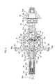
- the tool 20 includes a supporting member 22 and a cutting tool 23 supported to be pivotable about a pivot axis b located on a plane b' perpendicular to an axis a of the supporting member 22 in a plane view.
- the pivot axis b may be apart from the axis a or may intersect with the axis a.
- the supporting member 22 has a round rod shape and has on its right end portion a holder portion 22a gripped by a tool changer or the like, and its tapered mating portion 22b formed continuously from the holder portion 22a is fixedly mated with a mating hole 6b of the tool spindle 6a.
- a housing/support portion 22c supporting the cutting tool 23 in a housed state is formed in a slit shape.
- the cutting tool 23 is disposed in the housing/support portion 22c and is pivotally supported by a support shaft 19 coaxially arranged with the pivot axis b.
- a chip (cutting edge) 23a is bolted to a tip of the cutting tool 23, and a contact point where a tip of the chip 23a comes into contact with a surface to be machined is a machining point P.
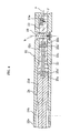
- the supporting member 22 has a left end portion 22e supported by a chuck 28 of the first spindle headstock 3 via a rotary bush 37 and is rotatable and movable in an axial direction. Further, in a left portion of the supporting member 22, a linear support hole 22d is formed coaxially with the axis a so as to communicate with the housing/support portion 22c. In the support hole 22d, a drive shaft 24 is disposed to be slidable in the axial direction. A rear end portion 25a of a link member 25 is coupled to a right end portion 24a of the drive shaft 24 via a coupling pin 25a'. Further, a tip portion 25b of the link member 25 is coupled to the cutting tool 23 via a coupling pin 25b'.
- the coupling pin 25b' is located at a position deviated from the pivot axis b of the cutting tool 23. Further, the cutting tool 23 has a slit 23c which is formed at its portion facing the link member 25 to avoid the interference with the link member 25, and a front portion of the link member 25 is located in the slit 23c. The cutting tool 23 pivots about the pivot axis b according to forward or backward movement of the drive shaft 24.
- a left portion of the drive shaft 24 has a small diameter, and a guide plate 24c and an end plate 24d are bolted to a left end surface of this small-diameter portion 24b.
- a biasing spring 26 is interposed between the guide plate 24c and a stepped portion of the support hole 22d to bias the drive shaft 24 leftward in the drawing.
- a guide pin 27 is buried in the support hole 22d portion of the supporting member 22.
- a tip portion 27a of the guide pin 27 is slidably mated with a guide groove 24e formed in a groove shape in the supporting member 22, whereby the drive shaft 24 rotates with the supporting member 22 and independently moves in the axial direction.
- a taper portion 29a at a tip of a pusher 29 is engaged with an engagement hole formed in an axis portion of the end plate 24d.
- the pusher 29 is disposed in a draw pipe 3b, which is disposed in the first spindle headstock 3, via a bearing 29b to be rotatable and slidable in the axial direction.
- the draw pipe 3b is disposed in a first spindle 3a disposed in the first spindle headstock 3 and a chuck-cylinder 30a is connected to a left end portion of the draw pipe 3b.
- a pusher driving mechanism 31 is connected to a left end portion of the pusher 29.
- the pusher driving mechanism 31 has a driving member 32 supporting the left end portion of the pusher 29 by a bearing 32a so as to allow the pusher 20 to rotate and move in the axial direction, a ball screw 33 screwed into a nut member 32b fixed to the driving member 32, and a servomotor 34 coupled to the ball screw 33 via a coupling 34a.
- Front and rear end portions of the ball screw 33 are supported by a base member 36 via bearings 35a, 35a.
- the pusher driving mechanism 31 functions as a pivot driving mechanism moving the pusher 29 back and forth by the rotation of the servomotor 34, thereby pivoting the cutting tool 23 via the drive shaft 24 and the link member 25.
- the chuck 28 of the first spindle headstock 3 of the composite lathe 1 functions as a workpiece holding mechanism positioning and holding a flange portion 21 c of the differential gear case 21.
- the tool spindle 6a functions as an axial feed mechanism rotating the the tool 20 about its axis a and controlling the axial-direction (Z-axis direction) position of the tool 20.
- the operation of the pusher driving mechanism 31 and the operation of the third spindle 6, that is, of the tool spindle 6a are realized by a controller (not shown) provided in the composite lathe 1. That is, a controller for dedicated control for realizing the present invention is not necessary.
- the differential gear case 21 as an object to be machined has left and right boss portions 21 a, 21 b and the flange portion 21 c, and left and right through holes 21 a', 21 b' are formed in the left and right boss portions 21 a, 21 b.
- the differential gear case 21 further has, on its inner surface, a spherical surface portion m 1 in a spherical shape, and a right bearing surface m2 and a left bearing surface m3 which are flat surfaces perpendicular to the axis a.
- a claw 28a of the chuck 28 of the first spindle headstock 3 grips the flange portion 21c of the differential gear case 21 to hold the differential gear case 21 at a predetermined Z-axis direction position (see FIG. 3 ).
- the tool spindle 6a is rotated about the Y axis so as to be coaxial with the first spindle headstock 3 and its Y-axis direction and X-axis direction positions are controlled.
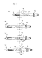
- the left portion of the supporting member 22 of the tool 20 is inserted through the through holes 21b', 21a' in the differential gear case 21 from the right, and the taper portion 22b at the right end of the tool 20 is mated with the mating hole 6b of the tool spindle 6a, and the left end portion 22e of the supporting member 22 is supported by the chuck 28 via the rotary bush 37 (see FIG 5 ).
- the pusher 29 and the supporting member 22 are moved leftward in synchronization, and the cutting tool 23 portion is made to enter the differential gear case 21 to be located at a machining start position (see FIG 6(b) ).
- the positions of the drive shaft 24 and the supporting member 22 are controlled so that the chip 23a of the cutting tool 23 moves on the right bearing surface m2 along a machining line orthogonal to the axis a.
- the cutting tool 23 pivots about the support shaft 19.
- the Z-axis direction position of the tool spindle 6a is controlled so that the machining point P' moves rightward in the Z-axis direction by c simultaneously with the pivoting so as to coincide with the right bearing surface m2.
- the machining point P moves linearly along the machining line on the right bearing surface m2 (see FIG 6(d) and FIG 7 ).
- the pusher driving mechanism 31 moves the pusher 29 rightward so that the pivot angle of the cutting tool 23 is kept 0.
- the tool spindle 6a slightly rotates the supporting member 22, and as a result, rotates the cutting tool 23, about the axis a, followed by the machining along a subsequent machining line. Repeating this operation realizes the machining of the right bearing surface m2 orthogonal to the axis a.
- the left bearing surface m3 is machined in the same manner.
- the supporting member 22 is moved in the direction of the axis a in accordance with an increase in the pivot angle of the cutting tool 23 at the time of the machining of the flat surface portions, and only the pivot angle of the cutting tool 23 is changed and the position in the direction of the axis a is fixed at the time of the machining of the spherical surface portions m2', m3'.
- the tool spindle 6a moves the supporting member 22 rightward in accordance with the increase in the pivot angle ⁇ of the cutting tool 23 so that the machining point P of the cutting tool 23 moves rightward, that is, moves toward the flat surface to be machined, which enables easy and sure machining even when the surface to be machined is a flat surface perpendicular to the axis a.
- a Z-axis moving function of the tool spindle 6a that a conventional composite lathe has is utilized, and therefore, the function of the existing composite lathe can be used to realize the machining of not only a spherical surface to be machined but also a flat bearing surface.
- the present invention is also capable of adopting a cutting tool having cutting edges at both ends, though the case where the cutting tool has the cutting edge only at one end is described in the foregoing embodiment.
- an object to be machined may be fixed on the bed via a jig, though the case where the differential gear case 21 is held by the chuck 28 of the first spindle headstock 3 is described in the foregoing embodiment.
- the differential gear case (workpiece) 21 is fixedly held, and the pivoting of the cutting tool 23 and the rotation of the support shaft 22 are controlled so that the machining point P of the chip 23a depicts a desired machining line.
- the differential gear case 21 may be rotary driven.
- the inner surface can be machined in such a manner that the pivot angle of the cutting tool 23 and the rotation angle and the axial-direction position of the supporting member 22 are controlled so that the machining point P of the chip 23a is located at a desired position, and in this state, the differential gear case 21 is rotated.
- the differential gear case 21 is gripped by the chuck 28 of the first spindle headstock 3, and, for example, in FIG 7 , the differential gear case 21 is rotated about the axis a while the machining point P is moved from P1 shown by the solid line to P2 shown by the chain line, to P3 shown by the two-dot chain line, and further to P4 shown by the broken line.
- This operation can realize the machining of a flat surface.
- the differential gear case 21 is gripped by the chuck 28 of the first spindle headstock 3 and at the same time is rotated at a required rotation speed in a required rotation direction. Then, a depth of cut by a desired outer tool T attached to the turret 31 is controlled, and the position of the machining point P of the inner tool 20, and its rotation speed and rotation direction are appropriately and selectively controlled, similarly to the embodiment described above.
- the rotation speed for machining the outer surface to be machined of the workpiece and the rotation speed for machining its inner surface to be machined can be set equal or can be set to any different rotation speeds. That is, the rotation speed at the time of the machining of the outer surface to be machined is the rotation speed of the workpiece, and the rotation speed at the time of the machining of the inner surface to be machined is a relative speed between the rotation speed of the workpiece and the rotation speed of the supporting member 22, that is, of the inner tool 20.
- the depth of cut by the outer tool T is controlled while the differential case 21 is rotated at 500 rpm.
- the pivot angle of the cutting tool 23 and the axial-direction position of the supporting member 22 are controlled so that the machining point P is located at a desired position, and at the same time, the supporting member 22 is rotated at 500 rpm in the reverse direction to the aforesaid direction. This can realize the simultaneous machining of the inner surface to be machined and the outer surface to be machined of the differential gear case 21 at different rotation speeds.
- the depth of cut by the outer tool T is controlled while the differential gear case 21 is rotated at 500 rpm.
- the supporting member 22 is rotated at 200 rpm in the same direction as the rotation direction of the differential gear case 21.
Applications Claiming Priority (1)
| Application Number | Priority Date | Filing Date | Title |
|---|---|---|---|
| JP2008044180A JP5094465B2 (ja) | 2008-02-26 | 2008-02-26 | 工作機械及び該工作機械を用いたワークの内表面加工方法 |
Publications (3)
| Publication Number | Publication Date |
|---|---|
| EP2095896A2 true EP2095896A2 (fr) | 2009-09-02 |
| EP2095896A3 EP2095896A3 (fr) | 2017-06-21 |
| EP2095896B1 EP2095896B1 (fr) | 2018-10-31 |
Family
ID=40875228
Family Applications (1)
| Application Number | Title | Priority Date | Filing Date |
|---|---|---|---|
| EP09002708.7A Not-in-force EP2095896B1 (fr) | 2008-02-26 | 2009-02-25 | Machine-outil et procédé d'usinage de la surface interne d'une pièce de travail en utilisant la machine outil |
Country Status (3)
| Country | Link |
|---|---|
| US (1) | US8146464B2 (fr) |
| EP (1) | EP2095896B1 (fr) |
| JP (1) | JP5094465B2 (fr) |
Cited By (11)
| Publication number | Priority date | Publication date | Assignee | Title |
|---|---|---|---|---|
| CN102441677A (zh) * | 2011-11-17 | 2012-05-09 | 台州市精力轴承有限公司 | 轴承套圈数控加工机床 |
| CN102107285B (zh) * | 2009-12-23 | 2012-07-11 | 中国有色(沈阳)冶金机械有限公司 | 一种立式车床球面加工的仿型装置 |
| CN103157813A (zh) * | 2013-03-07 | 2013-06-19 | 连云港职业技术学院 | 用于圆环面及球面加工的复合车削装置 |
| CN104227027A (zh) * | 2014-09-02 | 2014-12-24 | 浙江美德机械有限公司 | 球形产品专用车床 |
| CN108097985A (zh) * | 2018-02-02 | 2018-06-01 | 东莞市丞翔精密五金有限公司 | 一种法线纹加工机 |
| CN110125691A (zh) * | 2019-05-30 | 2019-08-16 | 福建泉州超晟数控机械有限公司 | 一种立式数控雕刻机及雕刻头调换方法 |
| CN110976959A (zh) * | 2019-12-23 | 2020-04-10 | 武金峰 | 一种冷拉型钢型材现场使用可调式快速钻孔加工机械 |
| CN112720023A (zh) * | 2021-01-19 | 2021-04-30 | 桂林航天工业学院 | 一种外球面加工用的高效车削装置 |
| EP3718666A4 (fr) * | 2017-12-01 | 2021-07-07 | Haru Technique Laboratory Inc. | Outil de coupe pour l'usinage de boîtiers de différentiel, dispositif d'usinage de boîtier de différentiel et procédé d'usinage de boîtier de différentiel |
| CN114352319A (zh) * | 2022-01-10 | 2022-04-15 | 中国水电基础局有限公司 | 大断面水工隧洞复合型偏压洞段施工方法 |
| CN114871833A (zh) * | 2022-06-07 | 2022-08-09 | 中山市捷上同程数控机床有限公司 | 一种应用于动力刀塔上可翻转工件的装置 |
Families Citing this family (18)
| Publication number | Priority date | Publication date | Assignee | Title |
|---|---|---|---|---|
| GB2472448A (en) * | 2009-08-07 | 2011-02-09 | Univ Sheffield | Compact Machine Tool with Secure Mount to Workpiece |
| JPWO2011027728A1 (ja) | 2009-09-02 | 2013-02-04 | 日本曹達株式会社 | ヒドロキシアルキルセルロースを含むコーティング剤 |
| JP5411044B2 (ja) * | 2010-03-31 | 2014-02-12 | 株式会社新機械技研 | デフケース内面加工方法及びデフケース内面加工手段 |
| JP5557587B2 (ja) * | 2010-04-28 | 2014-07-23 | 富士機械製造株式会社 | 中空ワークの内面加工装置 |
| AT511195B1 (de) * | 2011-01-28 | 2012-10-15 | Wfl Millturn Tech Gmbh & Co Kg | Verfahren zur verringerung der exzentrizität der innen- zur aussenfläche |
| CN102430763B (zh) * | 2011-09-08 | 2013-09-11 | 中国航空工业第六一八研究所 | 一种高纯铝类薄壁零件内球面的精密加工方法 |
| JP5854811B2 (ja) * | 2011-12-19 | 2016-02-09 | Dmg森精機株式会社 | 工作機械 |
| CN102773498B (zh) * | 2012-08-16 | 2015-01-07 | 保定天威英利新能源有限公司 | 一种多线切割机导轮的开槽方法 |
| CN102935584B (zh) * | 2012-11-21 | 2014-11-05 | 武汉船用机械有限责任公司 | 一种配油器壳体的加工方法 |
| CN103447948B (zh) * | 2013-08-15 | 2015-10-28 | 张满九 | 可转动磨床卡盘连接结构 |
| US20160207116A1 (en) * | 2015-01-20 | 2016-07-21 | United Technologies Corporation | Method to machine deep features using a lathe |
| CN107322009B (zh) * | 2017-08-06 | 2018-10-30 | 长沙达豪机械设备有限公司 | 汽车轴承用自动精密车边设备及其车边方法 |
| CN107322010B (zh) * | 2017-08-06 | 2018-10-30 | 长沙达豪机械设备有限公司 | 汽车用轴承的车边机及其车边方法 |
| US20200331080A1 (en) * | 2019-04-16 | 2020-10-22 | United Technologies Corporation | Lockout for deep reach machining tool |
| KR102138119B1 (ko) * | 2019-05-17 | 2020-07-27 | (주)화영 | 선박 엔진용 펌프 스테이션 하우징의 스와쉬 플레이트 베어링시트 절삭유니트 |
| CN111195735B (zh) * | 2020-01-22 | 2021-07-23 | 重庆精惠工业服务有限公司 | 一种切口倒角专用机床 |
| CN111266607A (zh) * | 2020-02-20 | 2020-06-12 | 盐城威佳机床制造有限公司 | 一种刀具可收缩的车削组合机床 |
| CN113145870B (zh) * | 2021-04-28 | 2024-01-12 | 连云港职业技术学院 | 一种环面车削装置 |
Citations (1)
| Publication number | Priority date | Publication date | Assignee | Title |
|---|---|---|---|---|
| US6318220B1 (en) | 2000-03-23 | 2001-11-20 | Malpal, Inc. | System and method for finish machining differential housings |
Family Cites Families (10)
| Publication number | Priority date | Publication date | Assignee | Title |
|---|---|---|---|---|
| US4176565A (en) * | 1978-09-05 | 1979-12-04 | Siegfried Schulz | Spherical bearing seat cutter machine |
| IT1166100B (it) * | 1979-09-03 | 1987-04-29 | Ansaldo Spa | Alesatore per alberi cavi |
| DE3206387A1 (de) * | 1982-02-22 | 1983-09-01 | Hilti AG, 9494 Schaan | Bohrwerkzeug fuer hinterschnittene bohrungen |
| JPS61252001A (ja) * | 1985-04-29 | 1986-11-10 | Mazda Motor Corp | 球面加工機 |
| DE4104474C1 (fr) * | 1991-02-14 | 1992-04-02 | Cross Europa-Werk Gmbh, 7317 Wendlingen, De | |
| ES2174053T3 (es) * | 1995-03-03 | 2002-11-01 | Komet Praezisionswerkzeuge | Accionamiento de posicionado, especialmente para la aplicacion en maquinas herramienta asi como cabezal con un accionamiento de posicionado de esta clase. |
| JP2002011603A (ja) * | 2000-06-23 | 2002-01-15 | Yamazaki Mazak Corp | 旋削加工工具 |
| JP2004237418A (ja) * | 2003-02-07 | 2004-08-26 | Fuji Seiko Ltd | 切削刃具ホルダおよび袋状被加工物の切削加工方法 |
| JP4572133B2 (ja) * | 2005-03-28 | 2010-10-27 | 富士機械製造株式会社 | 中空ワークの内面加工装置 |
| US8015902B2 (en) * | 2009-04-09 | 2011-09-13 | Mori Seiki Co., Ltd. | Machine tool and workpiece inner surface machining method using the machine tool |
-
2008
- 2008-02-26 JP JP2008044180A patent/JP5094465B2/ja active Active
-
2009
- 2009-02-25 EP EP09002708.7A patent/EP2095896B1/fr not_active Not-in-force
- 2009-02-25 US US12/392,826 patent/US8146464B2/en active Active - Reinstated
Patent Citations (1)
| Publication number | Priority date | Publication date | Assignee | Title |
|---|---|---|---|---|
| US6318220B1 (en) | 2000-03-23 | 2001-11-20 | Malpal, Inc. | System and method for finish machining differential housings |
Cited By (17)
| Publication number | Priority date | Publication date | Assignee | Title |
|---|---|---|---|---|
| CN102107285B (zh) * | 2009-12-23 | 2012-07-11 | 中国有色(沈阳)冶金机械有限公司 | 一种立式车床球面加工的仿型装置 |
| CN102441677A (zh) * | 2011-11-17 | 2012-05-09 | 台州市精力轴承有限公司 | 轴承套圈数控加工机床 |
| CN103157813A (zh) * | 2013-03-07 | 2013-06-19 | 连云港职业技术学院 | 用于圆环面及球面加工的复合车削装置 |
| CN103157813B (zh) * | 2013-03-07 | 2015-07-29 | 连云港职业技术学院 | 用于圆环面及球面加工的复合车削装置 |
| CN104227027A (zh) * | 2014-09-02 | 2014-12-24 | 浙江美德机械有限公司 | 球形产品专用车床 |
| US11278966B2 (en) | 2017-12-01 | 2022-03-22 | Haru Technique Laboratory Inc. | Cutting tool for machining differential case, machining apparatus for differential case and machining method for differential case |
| EP3718666A4 (fr) * | 2017-12-01 | 2021-07-07 | Haru Technique Laboratory Inc. | Outil de coupe pour l'usinage de boîtiers de différentiel, dispositif d'usinage de boîtier de différentiel et procédé d'usinage de boîtier de différentiel |
| CN108097985A (zh) * | 2018-02-02 | 2018-06-01 | 东莞市丞翔精密五金有限公司 | 一种法线纹加工机 |
| CN108097985B (zh) * | 2018-02-02 | 2023-07-18 | 东莞市丞翔精密五金有限公司 | 一种法线纹加工机 |
| CN110125691A (zh) * | 2019-05-30 | 2019-08-16 | 福建泉州超晟数控机械有限公司 | 一种立式数控雕刻机及雕刻头调换方法 |
| CN110125691B (zh) * | 2019-05-30 | 2023-12-26 | 福建泉州超晟数控机械有限公司 | 一种立式数控雕刻机及雕刻头调换方法 |
| CN110976959B (zh) * | 2019-12-23 | 2021-01-19 | 苏州苏玛精密型钢有限公司 | 一种冷拉型钢型材现场使用可调式快速钻孔加工机械 |
| CN110976959A (zh) * | 2019-12-23 | 2020-04-10 | 武金峰 | 一种冷拉型钢型材现场使用可调式快速钻孔加工机械 |
| CN112720023A (zh) * | 2021-01-19 | 2021-04-30 | 桂林航天工业学院 | 一种外球面加工用的高效车削装置 |
| CN114352319A (zh) * | 2022-01-10 | 2022-04-15 | 中国水电基础局有限公司 | 大断面水工隧洞复合型偏压洞段施工方法 |
| CN114352319B (zh) * | 2022-01-10 | 2024-02-06 | 中国水电基础局有限公司 | 大断面水工隧洞复合型偏压洞段施工方法 |
| CN114871833A (zh) * | 2022-06-07 | 2022-08-09 | 中山市捷上同程数控机床有限公司 | 一种应用于动力刀塔上可翻转工件的装置 |
Also Published As
| Publication number | Publication date |
|---|---|
| EP2095896B1 (fr) | 2018-10-31 |
| JP2009202247A (ja) | 2009-09-10 |
| US20090217792A1 (en) | 2009-09-03 |
| JP5094465B2 (ja) | 2012-12-12 |
| EP2095896A3 (fr) | 2017-06-21 |
| US8146464B2 (en) | 2012-04-03 |
Similar Documents
| Publication | Publication Date | Title |
|---|---|---|
| EP2095896B1 (fr) | Machine-outil et procédé d'usinage de la surface interne d'une pièce de travail en utilisant la machine outil | |
| US8015902B2 (en) | Machine tool and workpiece inner surface machining method using the machine tool | |
| US9162289B2 (en) | Machine tool apparatus and method | |
| JP4611833B2 (ja) | 差動ケースの内面加工方法及び内面加工装置 | |
| EP3162478B1 (fr) | Machine-outil et procédé d'usinage | |
| JP2004114238A (ja) | 複合加工工作機械および複合加工工作機械における加工方法 | |
| US11759900B2 (en) | Machining apparatus for differential case | |
| JP6105255B2 (ja) | 旋盤およびワークの加工方法 | |
| KR20150009957A (ko) | 회전 공구 유닛을 장착 가능한 공작 기계 | |
| US20220226909A1 (en) | Cutting tool for boring, machining apparatus for boring and method for boring | |
| CN102325628B (zh) | 车床 | |
| JP4572133B2 (ja) | 中空ワークの内面加工装置 | |
| WO2016013307A1 (fr) | Machine-outil, unité d'outil, et procédé d'usinage | |
| CN102233437B (zh) | 中空工件的内表面加工装置 | |
| JP2014034073A (ja) | 複合工作機械 | |
| US11123804B2 (en) | Tool holder for lathe and lathe provided with the tool holder | |
| JP2012161904A (ja) | 複合工具、加工方法および工作機械 | |
| JPH1015703A (ja) | 多機能旋盤 | |
| JP2010076048A (ja) | 複合加工工作機械 | |
| JP2008087144A (ja) | 主軸移動型自動旋盤 | |
| JP2009066672A (ja) | 中空ワークの内面加工装置 | |
| CN210818384U (zh) | 一种双主轴的车铣复合机床 | |
| JPH10315005A (ja) | Nc自動旋盤 | |
| JP2003205403A (ja) | 回転軸主軸台 | |
| JPH05245703A (ja) | Y軸加工装置付nc旋盤 |
Legal Events
| Date | Code | Title | Description |
|---|---|---|---|
| PUAI | Public reference made under article 153(3) epc to a published international application that has entered the european phase |
Free format text: ORIGINAL CODE: 0009012 |
|
| AK | Designated contracting states |
Kind code of ref document: A2 Designated state(s): AT BE BG CH CY CZ DE DK EE ES FI FR GB GR HR HU IE IS IT LI LT LU LV MC MK MT NL NO PL PT RO SE SI SK TR |
|
| AX | Request for extension of the european patent |
Extension state: AL BA RS |
|
| RAP1 | Party data changed (applicant data changed or rights of an application transferred) |
Owner name: DMG MORI SEIKI CO., LTD. |
|
| PUAL | Search report despatched |
Free format text: ORIGINAL CODE: 0009013 |
|
| AK | Designated contracting states |
Kind code of ref document: A3 Designated state(s): AT BE BG CH CY CZ DE DK EE ES FI FR GB GR HR HU IE IS IT LI LT LU LV MC MK MT NL NO PL PT RO SE SI SK TR |
|
| AX | Request for extension of the european patent |
Extension state: AL BA RS |
|
| RIC1 | Information provided on ipc code assigned before grant |
Ipc: B23B 29/02 20060101ALI20170516BHEP Ipc: B23B 5/40 20060101AFI20170516BHEP |
|
| STAA | Information on the status of an ep patent application or granted ep patent |
Free format text: STATUS: REQUEST FOR EXAMINATION WAS MADE |
|
| 17P | Request for examination filed |
Effective date: 20171206 |
|
| RBV | Designated contracting states (corrected) |
Designated state(s): AT BE BG CH CY CZ DE DK EE ES FI FR GB GR HR HU IE IS IT LI LT LU LV MC MK MT NL NO PL PT RO SE SI SK TR |
|
| AKX | Designation fees paid |
Designated state(s): AT BE BG CH CY CZ DE DK EE ES FI FR GB GR HR HU IE IS IT LI LT LU LV MC MK MT NL NO PL PT RO SE SI SK TR |
|
| AXX | Extension fees paid |
Extension state: RS Extension state: BA Extension state: AL |
|
| GRAP | Despatch of communication of intention to grant a patent |
Free format text: ORIGINAL CODE: EPIDOSNIGR1 |
|
| STAA | Information on the status of an ep patent application or granted ep patent |
Free format text: STATUS: GRANT OF PATENT IS INTENDED |
|
| GRAJ | Information related to disapproval of communication of intention to grant by the applicant or resumption of examination proceedings by the epo deleted |
Free format text: ORIGINAL CODE: EPIDOSDIGR1 |
|
| GRAP | Despatch of communication of intention to grant a patent |
Free format text: ORIGINAL CODE: EPIDOSNIGR1 |
|
| INTG | Intention to grant announced |
Effective date: 20180525 |
|
| INTG | Intention to grant announced |
Effective date: 20180604 |
|
| GRAS | Grant fee paid |
Free format text: ORIGINAL CODE: EPIDOSNIGR3 |
|
| GRAA | (expected) grant |
Free format text: ORIGINAL CODE: 0009210 |
|
| STAA | Information on the status of an ep patent application or granted ep patent |
Free format text: STATUS: THE PATENT HAS BEEN GRANTED |
|
| AK | Designated contracting states |
Kind code of ref document: B1 Designated state(s): AT BE BG CH CY CZ DE DK EE ES FI FR GB GR HR HU IE IS IT LI LT LU LV MC MK MT NL NO PL PT RO SE SI SK TR |
|
| REG | Reference to a national code |
Ref country code: CH Ref legal event code: EP Ref country code: GB Ref legal event code: FG4D |
|
| REG | Reference to a national code |
Ref country code: AT Ref legal event code: REF Ref document number: 1058788 Country of ref document: AT Kind code of ref document: T Effective date: 20181115 |
|
| REG | Reference to a national code |
Ref country code: DE Ref legal event code: R096 Ref document number: 602009055323 Country of ref document: DE |
|
| REG | Reference to a national code |
Ref country code: IE Ref legal event code: FG4D |
|
| REG | Reference to a national code |
Ref country code: NL Ref legal event code: MP Effective date: 20181031 |
|
| REG | Reference to a national code |
Ref country code: LT Ref legal event code: MG4D |
|
| REG | Reference to a national code |
Ref country code: AT Ref legal event code: MK05 Ref document number: 1058788 Country of ref document: AT Kind code of ref document: T Effective date: 20181031 |
|
| PG25 | Lapsed in a contracting state [announced via postgrant information from national office to epo] |
Ref country code: AT Free format text: LAPSE BECAUSE OF FAILURE TO SUBMIT A TRANSLATION OF THE DESCRIPTION OR TO PAY THE FEE WITHIN THE PRESCRIBED TIME-LIMIT Effective date: 20181031 Ref country code: LV Free format text: LAPSE BECAUSE OF FAILURE TO SUBMIT A TRANSLATION OF THE DESCRIPTION OR TO PAY THE FEE WITHIN THE PRESCRIBED TIME-LIMIT Effective date: 20181031 Ref country code: NO Free format text: LAPSE BECAUSE OF FAILURE TO SUBMIT A TRANSLATION OF THE DESCRIPTION OR TO PAY THE FEE WITHIN THE PRESCRIBED TIME-LIMIT Effective date: 20190131 Ref country code: IS Free format text: LAPSE BECAUSE OF FAILURE TO SUBMIT A TRANSLATION OF THE DESCRIPTION OR TO PAY THE FEE WITHIN THE PRESCRIBED TIME-LIMIT Effective date: 20190228 Ref country code: FI Free format text: LAPSE BECAUSE OF FAILURE TO SUBMIT A TRANSLATION OF THE DESCRIPTION OR TO PAY THE FEE WITHIN THE PRESCRIBED TIME-LIMIT Effective date: 20181031 Ref country code: BG Free format text: LAPSE BECAUSE OF FAILURE TO SUBMIT A TRANSLATION OF THE DESCRIPTION OR TO PAY THE FEE WITHIN THE PRESCRIBED TIME-LIMIT Effective date: 20190131 Ref country code: ES Free format text: LAPSE BECAUSE OF FAILURE TO SUBMIT A TRANSLATION OF THE DESCRIPTION OR TO PAY THE FEE WITHIN THE PRESCRIBED TIME-LIMIT Effective date: 20181031 Ref country code: LT Free format text: LAPSE BECAUSE OF FAILURE TO SUBMIT A TRANSLATION OF THE DESCRIPTION OR TO PAY THE FEE WITHIN THE PRESCRIBED TIME-LIMIT Effective date: 20181031 Ref country code: HR Free format text: LAPSE BECAUSE OF FAILURE TO SUBMIT A TRANSLATION OF THE DESCRIPTION OR TO PAY THE FEE WITHIN THE PRESCRIBED TIME-LIMIT Effective date: 20181031 Ref country code: PL Free format text: LAPSE BECAUSE OF FAILURE TO SUBMIT A TRANSLATION OF THE DESCRIPTION OR TO PAY THE FEE WITHIN THE PRESCRIBED TIME-LIMIT Effective date: 20181031 |
|
| PG25 | Lapsed in a contracting state [announced via postgrant information from national office to epo] |
Ref country code: PT Free format text: LAPSE BECAUSE OF FAILURE TO SUBMIT A TRANSLATION OF THE DESCRIPTION OR TO PAY THE FEE WITHIN THE PRESCRIBED TIME-LIMIT Effective date: 20190301 Ref country code: NL Free format text: LAPSE BECAUSE OF FAILURE TO SUBMIT A TRANSLATION OF THE DESCRIPTION OR TO PAY THE FEE WITHIN THE PRESCRIBED TIME-LIMIT Effective date: 20181031 Ref country code: GR Free format text: LAPSE BECAUSE OF FAILURE TO SUBMIT A TRANSLATION OF THE DESCRIPTION OR TO PAY THE FEE WITHIN THE PRESCRIBED TIME-LIMIT Effective date: 20190201 Ref country code: SE Free format text: LAPSE BECAUSE OF FAILURE TO SUBMIT A TRANSLATION OF THE DESCRIPTION OR TO PAY THE FEE WITHIN THE PRESCRIBED TIME-LIMIT Effective date: 20181031 |
|
| PG25 | Lapsed in a contracting state [announced via postgrant information from national office to epo] |
Ref country code: DK Free format text: LAPSE BECAUSE OF FAILURE TO SUBMIT A TRANSLATION OF THE DESCRIPTION OR TO PAY THE FEE WITHIN THE PRESCRIBED TIME-LIMIT Effective date: 20181031 Ref country code: CZ Free format text: LAPSE BECAUSE OF FAILURE TO SUBMIT A TRANSLATION OF THE DESCRIPTION OR TO PAY THE FEE WITHIN THE PRESCRIBED TIME-LIMIT Effective date: 20181031 Ref country code: IT Free format text: LAPSE BECAUSE OF FAILURE TO SUBMIT A TRANSLATION OF THE DESCRIPTION OR TO PAY THE FEE WITHIN THE PRESCRIBED TIME-LIMIT Effective date: 20181031 |
|
| REG | Reference to a national code |
Ref country code: DE Ref legal event code: R097 Ref document number: 602009055323 Country of ref document: DE |
|
| PG25 | Lapsed in a contracting state [announced via postgrant information from national office to epo] |
Ref country code: RO Free format text: LAPSE BECAUSE OF FAILURE TO SUBMIT A TRANSLATION OF THE DESCRIPTION OR TO PAY THE FEE WITHIN THE PRESCRIBED TIME-LIMIT Effective date: 20181031 Ref country code: EE Free format text: LAPSE BECAUSE OF FAILURE TO SUBMIT A TRANSLATION OF THE DESCRIPTION OR TO PAY THE FEE WITHIN THE PRESCRIBED TIME-LIMIT Effective date: 20181031 Ref country code: SK Free format text: LAPSE BECAUSE OF FAILURE TO SUBMIT A TRANSLATION OF THE DESCRIPTION OR TO PAY THE FEE WITHIN THE PRESCRIBED TIME-LIMIT Effective date: 20181031 |
|
| PLBE | No opposition filed within time limit |
Free format text: ORIGINAL CODE: 0009261 |
|
| STAA | Information on the status of an ep patent application or granted ep patent |
Free format text: STATUS: NO OPPOSITION FILED WITHIN TIME LIMIT |
|
| REG | Reference to a national code |
Ref country code: CH Ref legal event code: PL |
|
| 26N | No opposition filed |
Effective date: 20190801 |
|
| GBPC | Gb: european patent ceased through non-payment of renewal fee |
Effective date: 20190225 |
|
| PG25 | Lapsed in a contracting state [announced via postgrant information from national office to epo] |
Ref country code: SI Free format text: LAPSE BECAUSE OF FAILURE TO SUBMIT A TRANSLATION OF THE DESCRIPTION OR TO PAY THE FEE WITHIN THE PRESCRIBED TIME-LIMIT Effective date: 20181031 Ref country code: LU Free format text: LAPSE BECAUSE OF NON-PAYMENT OF DUE FEES Effective date: 20190225 Ref country code: MC Free format text: LAPSE BECAUSE OF FAILURE TO SUBMIT A TRANSLATION OF THE DESCRIPTION OR TO PAY THE FEE WITHIN THE PRESCRIBED TIME-LIMIT Effective date: 20181031 |
|
| REG | Reference to a national code |
Ref country code: BE Ref legal event code: MM Effective date: 20190228 |
|
| REG | Reference to a national code |
Ref country code: IE Ref legal event code: MM4A |
|
| PG25 | Lapsed in a contracting state [announced via postgrant information from national office to epo] |
Ref country code: LI Free format text: LAPSE BECAUSE OF NON-PAYMENT OF DUE FEES Effective date: 20190228 Ref country code: CH Free format text: LAPSE BECAUSE OF NON-PAYMENT OF DUE FEES Effective date: 20190228 |
|
| PG25 | Lapsed in a contracting state [announced via postgrant information from national office to epo] |
Ref country code: IE Free format text: LAPSE BECAUSE OF NON-PAYMENT OF DUE FEES Effective date: 20190225 Ref country code: GB Free format text: LAPSE BECAUSE OF NON-PAYMENT OF DUE FEES Effective date: 20190225 |
|
| PG25 | Lapsed in a contracting state [announced via postgrant information from national office to epo] |
Ref country code: FR Free format text: LAPSE BECAUSE OF NON-PAYMENT OF DUE FEES Effective date: 20190228 Ref country code: BE Free format text: LAPSE BECAUSE OF NON-PAYMENT OF DUE FEES Effective date: 20190228 |
|
| PG25 | Lapsed in a contracting state [announced via postgrant information from national office to epo] |
Ref country code: TR Free format text: LAPSE BECAUSE OF FAILURE TO SUBMIT A TRANSLATION OF THE DESCRIPTION OR TO PAY THE FEE WITHIN THE PRESCRIBED TIME-LIMIT Effective date: 20181031 |
|
| PG25 | Lapsed in a contracting state [announced via postgrant information from national office to epo] |
Ref country code: MT Free format text: LAPSE BECAUSE OF NON-PAYMENT OF DUE FEES Effective date: 20190225 |
|
| PG25 | Lapsed in a contracting state [announced via postgrant information from national office to epo] |
Ref country code: CY Free format text: LAPSE BECAUSE OF FAILURE TO SUBMIT A TRANSLATION OF THE DESCRIPTION OR TO PAY THE FEE WITHIN THE PRESCRIBED TIME-LIMIT Effective date: 20181031 |
|
| PGFP | Annual fee paid to national office [announced via postgrant information from national office to epo] |
Ref country code: DE Payment date: 20210217 Year of fee payment: 13 |
|
| PG25 | Lapsed in a contracting state [announced via postgrant information from national office to epo] |
Ref country code: HU Free format text: LAPSE BECAUSE OF FAILURE TO SUBMIT A TRANSLATION OF THE DESCRIPTION OR TO PAY THE FEE WITHIN THE PRESCRIBED TIME-LIMIT; INVALID AB INITIO Effective date: 20090225 |
|
| PG25 | Lapsed in a contracting state [announced via postgrant information from national office to epo] |
Ref country code: MK Free format text: LAPSE BECAUSE OF FAILURE TO SUBMIT A TRANSLATION OF THE DESCRIPTION OR TO PAY THE FEE WITHIN THE PRESCRIBED TIME-LIMIT Effective date: 20181031 |
|
| REG | Reference to a national code |
Ref country code: DE Ref legal event code: R119 Ref document number: 602009055323 Country of ref document: DE |
|
| PG25 | Lapsed in a contracting state [announced via postgrant information from national office to epo] |
Ref country code: DE Free format text: LAPSE BECAUSE OF NON-PAYMENT OF DUE FEES Effective date: 20220901 |