EP2091114A2 - Bürstenhalter - Google Patents
Bürstenhalter Download PDFInfo
- Publication number
- EP2091114A2 EP2091114A2 EP09151429A EP09151429A EP2091114A2 EP 2091114 A2 EP2091114 A2 EP 2091114A2 EP 09151429 A EP09151429 A EP 09151429A EP 09151429 A EP09151429 A EP 09151429A EP 2091114 A2 EP2091114 A2 EP 2091114A2
- Authority
- EP
- European Patent Office
- Prior art keywords
- terminal
- brush
- direct current
- terminals
- cut
- Prior art date
- Legal status (The legal status is an assumption and is not a legal conclusion. Google has not performed a legal analysis and makes no representation as to the accuracy of the status listed.)
- Withdrawn
Links
- 238000005520 cutting process Methods 0.000 claims abstract description 22
- 239000011347 resin Substances 0.000 claims description 8
- 229920005989 resin Polymers 0.000 claims description 8
- 239000003990 capacitor Substances 0.000 description 19
- 238000000034 method Methods 0.000 description 10
- 238000004519 manufacturing process Methods 0.000 description 8
- 238000000465 moulding Methods 0.000 description 8
- 238000005476 soldering Methods 0.000 description 6
- 238000003466 welding Methods 0.000 description 6
- 230000000694 effects Effects 0.000 description 4
- 230000002093 peripheral effect Effects 0.000 description 4
- 238000004080 punching Methods 0.000 description 4
- LTMHDMANZUZIPE-PUGKRICDSA-N digoxin Chemical compound C1[C@H](O)[C@H](O)[C@@H](C)O[C@H]1O[C@@H]1[C@@H](C)O[C@@H](O[C@@H]2[C@H](O[C@@H](O[C@@H]3C[C@@H]4[C@]([C@@H]5[C@H]([C@]6(CC[C@@H]([C@@]6(C)[C@H](O)C5)C=5COC(=O)C=5)O)CC4)(C)CC3)C[C@@H]2O)C)C[C@@H]1O LTMHDMANZUZIPE-PUGKRICDSA-N 0.000 description 2
- 238000012986 modification Methods 0.000 description 2
- 230000004048 modification Effects 0.000 description 2
- 239000000853 adhesive Substances 0.000 description 1
- 230000001070 adhesive effect Effects 0.000 description 1
- 230000007423 decrease Effects 0.000 description 1
- 238000010586 diagram Methods 0.000 description 1
- 239000002184 metal Substances 0.000 description 1
- 238000003825 pressing Methods 0.000 description 1
- 230000001172 regenerating effect Effects 0.000 description 1
- 230000001629 suppression Effects 0.000 description 1
Images



Classifications
-
- H—ELECTRICITY
- H01—ELECTRIC ELEMENTS
- H01R—ELECTRICALLY-CONDUCTIVE CONNECTIONS; STRUCTURAL ASSOCIATIONS OF A PLURALITY OF MUTUALLY-INSULATED ELECTRICAL CONNECTING ELEMENTS; COUPLING DEVICES; CURRENT COLLECTORS
- H01R39/00—Rotary current collectors, distributors or interrupters
- H01R39/02—Details for dynamo electric machines
- H01R39/38—Brush holders
- H01R39/383—Brush holders characterised by the electrical connection to the brush holder
-
- H—ELECTRICITY
- H02—GENERATION; CONVERSION OR DISTRIBUTION OF ELECTRIC POWER
- H02K—DYNAMO-ELECTRIC MACHINES
- H02K11/00—Structural association of dynamo-electric machines with electric components or with devices for shielding, monitoring or protection
- H02K11/02—Structural association of dynamo-electric machines with electric components or with devices for shielding, monitoring or protection for suppression of electromagnetic interference
- H02K11/026—Suppressors associated with brushes, brush holders or their supports
-
- H—ELECTRICITY
- H02—GENERATION; CONVERSION OR DISTRIBUTION OF ELECTRIC POWER
- H02K—DYNAMO-ELECTRIC MACHINES
- H02K5/00—Casings; Enclosures; Supports
- H02K5/04—Casings or enclosures characterised by the shape, form or construction thereof
- H02K5/14—Means for supporting or protecting brushes or brush holders
- H02K5/143—Means for supporting or protecting brushes or brush holders for cooperation with commutators
- H02K5/148—Slidably supported brushes
-
- H—ELECTRICITY
- H02—GENERATION; CONVERSION OR DISTRIBUTION OF ELECTRIC POWER
- H02K—DYNAMO-ELECTRIC MACHINES
- H02K5/00—Casings; Enclosures; Supports
- H02K5/04—Casings or enclosures characterised by the shape, form or construction thereof
- H02K5/22—Auxiliary parts of casings not covered by groups H02K5/06-H02K5/20, e.g. shaped to form connection boxes or terminal boxes
- H02K5/225—Terminal boxes or connection arrangements
Definitions
- the invention relates to a brush holder including terminals, which form conducting paths connecting each brush, making a sliding contact with a commutator of a direct current rotating electrical machine, with a direct current source and a resin made holder body holding the terminals.
- a direct current motor which is a kind of direct current rotating electrical machine, includes a stator, an armature, commutators, and brushes.
- the stator has a yoke case and a magnet.
- the armature and the commutator are fixed to an outer peripheral portion of a rotating shaft of the direct current motor to form a rotator.
- the brush is fixed to the stator side to supply direct current to the rotator.
- the brushes are often held by a brush holder mounted to an opening of the yoke case.
- the commutator receives the direct current through the brushes to switch the direction of the current flowing in armature coils. Consequently, continuous torque is generated in the armature, and the rotator rotates.
- a noise filter is often provided in a circuit that connects the brushes with the direct current source.
- Fig. 11A shows an example of a circuit in which a capacitor C1, connected in parallel with the direct current source V M , is provided as a noise filter.
- Fig. 11B shows another example of a circuit, in which the capacitor C1 and choke coils L (L1, L2) are provided. In the example, the capacitor C1 is connected in parallel with the direct current source V M , and the choke coils L (L1, L2) are connected in series with electric power supply lines of the positive and negative electrodes.
- an amount and energy of the electromagnetic noise vary depending on an operation environment such as the load or the rotation speed of the motor.
- the effect on a circuit caused by the electromagnetic noise varies depending on an environment that the motor is located.
- the effect on a circuit caused by the electromagnetic noise varies depending on whether another electric circuit is located in the vicinity of the direct current motor, or whether a member such as a metal plate, serving as a shield against the electromagnetic noise, is located in the vicinity of the direct current motor.
- the noise filter including the choke coils, shown in Fig. 11B is not always necessary, and the configuration of the noise filter should be selected according to the operation and locating environments.
- JP 2003-79109A a brush holder is proposed in view of the above circumstances.
- a noise filter using the choke coils which is similar to that of Fig. 11B , may be mounted in the brush holder.
- whether or not to mount the choke coils may be determined at the time of the production.
- the brush holder is configured so as to accommodate a current carrying member, either a terminal plate or the choke coil, in each choke coil accommodating portion of the brush holder. Since the terminal plate functions as a conducting path, the circuit shown in Fig. 11A is formed by mounting the terminal plates to the circuit configured as shown in Fig. 11B , instead of the choke coils.
- the brush holder disclosed in JP 2003-79109A is excellent in that the same brush holder is usable irrespective of the presence or absence of the choke coils.
- a disadvantage lies in the fact that when the choke coils are not needed and the cost and the man hours may be saved, the terminal plates need to be mounted in the brush holder. The cost of the terminal plates is required and the man hours are not reduced. Consequently, the reduction effect of the production cost is limited.
- the similar disadvantage occurs in the direct current dynamo which is a kind of the direct current rotating electrical machine.
- a brush holder includes a plurality of terminals respectively forming conducting paths connecting brushes, each making a slidable contact with a commutator of a direct current rotating electrical machine, with a direct current source and a holder body made of resin and holding the terminals, wherein each terminal is formed including a pair of connecting terminals provided so as to sandwich a cut-off portion in which the conducting path is cut to mount an electrical component to the cut-off portion for connecting the electrical component in series with the conducting path, and a shorting path forming portion connecting one of the connecting terminals provided at a side of the direct current source with the brush to short the cut-off portion, wherein the holder body is formed having an opening, from which both surfaces of the shorting path forming portion are exposed to an exterior, for cutting the shorting path forming portion with the terminals held by the holder body.
- the shorting path forming portions are not cut with the terminal held by the holder body.
- the shoring path forming portions are cut with the terminal held by the holder body.
- the electrical component is connected with the connecting terminals and the current flows into an open path via the electrical component.
- the first circuit is formed without mounting any component, which substitutes for the electrical component, once the terminal is held by the holder body.
- the shorting path forming portion should be formed so as to be shorter than the length of the connection line from one of the connecting terminals to the brush via the cut-off portion and the other connecting terminal.
- the length of the shorting path forming portion remaining after the cutting is shorter than the connection line from one of the connecting terminals to the brush via the electrical component connecting in series.
- the remaining portions of each shorting path forming portion after the cutting become conducting paths and portions which are cut become open ends.
- the conducting path having the open end functions as an antenna.
- the shorting path forming portions should be short because each remaining portion of the shorting path forming portion after the cutting functions as an antenna.
- the shorting path forming portion is formed so that the remaining portions of each shorting path forming portion are short after the cutting.
- the brush holder may be formed in the following manner,
- the terminals are formed as a single unit so that the positive electrode conducting path, which connects with the brush connecting with the positive electrode of the direct current source, is connected with the negative electrode conducting path, which connects with the brush connecting with the negative electrode of the direct current source, at the connecting path, and the holder body is formed having the opening, from which both the surfaces of the connecting path are exposed to the exterior, for cutting the connecting path after the terminal is held by the holder body.
- the terminal is formed in the manner that the conducting paths, respectively connecting with the brushes having the different polarities, are integrated, thus reducing the man hours for mounting the terminal to the brush holder.
- the conducting paths, respectively connecting with the brushes having the different polarities have to be separated.
- the connecting path is cut after mounting the terminal, and the terminal is divided into the two conducting paths, i.e. the positive electrode conducting path and the negative electrode conducting path.
- the electrical component, connecting in series with the conducting path is mounted; the shorting path forming portions of the terminal are cut as described above. The cutting of the shorting path forming portions may be conducted at the same process as the cutting of the connecting path.
- the connecting path and the shorting path forming portions may be simultaneously cut by using an appropriate jig.
- the terminal cutting process is included in the production irrespective of whether or not the electrical component is mounted.
- the brush holder is produced in substantially the same man hours irrespective of the presence or absence of the electrical component.
- the terminal is integrally molded with the holder body.
- the terminal is integrally molded with the holder body by using a resin, the man hours for mounting the terminal to the holder body is reduced. As a result, productivity is improved. Further, integral molding allows the terminal to be securely held by the holder body. As described above, the shorting path forming portions and the connection path may be cut with the terminal held by the holder body. At that time, the terminal may be slightly lifted or come away from the holder body 11 due to the stress applied during the cutting. However, molding the terminal with the holder body intergrally decreases the potential for causing the situation, thus improving product quality.
- the electrical component mounted to the brush holder should be one of the choke coil and the thermistors.
- a filter circuit may be appropriately formed in the brush holder depending on the amount of the electromagnetic noise by using the choke coil as the electrical component. Further, the value of the series resistance is changed according to the amount of the current flowing into the direct current rotating electrical machine and the generated heat by using the thermistor as the electrical component. Thus, the amount of the current may be automatically controlled.
- Fig. 1 is a side view conceptually showing an example of a motor configuration
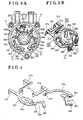
- Fig. 2A is a top view of a brush holder corresponding to a circuit configuration shown in Fig. 11A and Fig. 2B is a perspective view conceptually showing that components are mounted to the terminal;
- Fig. 3A is a top view corresponding to a circuit configuration shown in Fig.11B and Fig. 3B is a perspective view conceptually showing that components are mounted to the terminal;
- Fig. 4 is a perspective view of the terminal
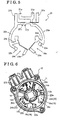
- Fig. 5 is a perspective view conceptually showing the terminal set in a mold at a time of insert-molding
- Fig. 6 is a perspective view of the brush holder after the insert-molding
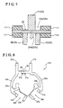
- Fig. 7 is an explanation view of a punching method
- Fig. 8 is a perspective view showing a terminal according to another embodiment
- Fig. 9 is a top view showing a terminal according to another embodiment.
- Fig. 10 is a top view showing a terminal according to another embodiment.
- Figs. 11A and 11B are circuit diagrams, each showing an example of a circuit connecting with a direct current source in the brush holder.
- Direct current rotating electrical machines include direct current motors and direct current dynamos. Electrically, the direct current motors and the direct current dynamos have similar configurations, and thus the direct current motor is used as an example in the description. Further, a type of an electrical circuit, included in a brush holder and connected with the direct current source, varies between a direct current motor and a direct current dynamo. Specifically, a feeder circuit is used in the direct current motor, and a regenerative circuit is used in the direct current dynamo. However, the configurations of these circuits are similar. Hence, the feeder circuit is used as an example hereinafter. As just described, it is obvious for those skilled in the art to apply the principles of the invention to the direct current dynamo, and thus detailed description regarding the direct current dynamo will be omitted.
- Fig. 1 is a side view schematically showing an example of a configuration of a motor 1 (the direct current rotating electrical machine).
- the motor 1 which is a direct current motor, is made up of a stator, an armature, commutators, and brushes.
- a reference numeral 2 shown in Fig. 1 represents a cup shaped yoke case.
- a permanent magnet or an electric magnet is fixed to an inner peripheral surface of the yoke case 2 to form the stator making up a field magnet.
- a rotating shaft 3 is rotatably housed in a space defined by the inner peripheral surface of the yoke case 2.
- the armature and the commutators are fixed to an outer peripheral portion of the rotating shaft 3 to form the rotator.
- the brush is supported by a brush holder 10 mounted to an opening of the yoke case 2.
- Figs. 2 is a top view of the brush holder 10
- Fig. 3 is a perspective view of a terminal 20 held by the brush holder 10.
- the terminal 20 is integrally molded with a holder body 11 by insert-molding to be held.
- Figs. 2A and 2B correspond to a circuit configuration shown in Fig. 11A
- Figs. 3A and 3B correspond to a circuit configuration shown in Fig. 11B .
- the brush holder 10 will be described with reference to Figs. 2A, 2B , 3A and 3B .
- details of the form of the terminal 20 are shown in Figs. 4 and 5 .
- the feeder circuit formed in the brush holder 10 will be described with reference to Figs. 2B and 11A . Further, Figs. 4 and 5 are referred to describe the circuit.
- the terminal 20 is made up of two components, i.e. a first terminal 20a and a second terminal 20b.
- the first terminal 20a is connected with a positive side (positive electrode) of a direct current source V M at a supply terminal 21a to form a positive electrode conducting path
- the second terminal 20b is connected with a negative side (negative electrode) of the direct current source V M at a supply terminal 21b to form a negative electrode conducting path.
- two supply terminals 21a and two supply terminals 21b are respectively provided to enable two different direct current sources to supply power to the circuit.
- the first and second terminals 20a and 20b are respectively connected with the positive and negative sides of the direct current source V M .
- the first and second terminals 20a and 20b are insulated when being held by the holder body 11.
- a capacitor C1 is connected between the positive and negative electrodes of the direct current source V M .
- a connecting terminal 27a, with which one terminal of the capacitor C1 is connected, is provided at the first terminal 20a, and a connecting terminal 27b, with which the other terminal of the capacitor C1 is connected, is provided at the second terminal 20b.
- the capacitor C1 is positioned between the connecting terminal 27a of the first terminal 20a and the connecting terminal 27b of the second terminal 20b and is connected in parallel with the direct current source V M .
- a first brush 5a (5) is connected with the first terminal 20a, and the voltage of the positive side of the direct current source V M is applied to the commutator through the brush 5a.
- a second brush 5b (5) is connected with the second terminal 20b, and the voltage of the negative side of the direct current source V M is applied to the commutator through the brush 5b.
- a brush connecting portion 26a, with which the first brush 5a is connected, is provided at the first terminal 20a, and a brush connecting portion 26b, with which the second brush 5b is connected, is provided at the second terminal 20b.
- the circuit shown in Fig. 11A is formed, and choke coils L, which may be respectively connected in series with conducting paths connecting each brush 5 with the direct current source V M , are not mounted.
- pairs of connecting terminals 22a-23a and 22b-23b, with which the choke coils L are connected are respectively formed at the first and second terminal 20a and 20b.
- the connecting terminals 22a and 23a of the first terminal 20a are formed so as to sandwich a cut-off portion 28a, in which the conducting path is cut for mounting the choke coil L1 thereto.
- the connecting terminals 22b and 23b of the second terminal 20b are formed so as to sandwich a cut-off portion 28b, in which the conducting path is cut for mounting the choke coil L2 thereto.
- the choke coils L are connected with the terminal 20 in the following manner.
- One terminal of the choke coil L1 is connected with the connecting terminal 22a, and the other terminal is connected with the connecting terminal 23 a, thereby mounting the choke coil L1 to the first terminal 20a so as to bridge the cut-off portion 28a.
- one terminal of the choke coil L2 is connected with the connecting terminal 22b and the other terminal is connected with the connecting terminal 23b, thereby mounting the choke coil L2 to the second terminal 20b so as to bridge the cut-off portion 28b.
- the conducting paths connecting each brush 5 and the direct current source V M are respectively interrupted at the cut-off portions 28a and 28b.
- shorting path forming portions 24a and 24b are respectively formed at the first and second terminal 20a and 20b.
- the shorting path forming portion 24a of the first terminal 20a connects the connecting terminal 22a formed at the direct current source side (the supply terminal 21a side) with the brush 5a to short (carry a current into) the cut-off portion 28a.
- the shorting path forming portion 24b of the second terminal 20b connects the connecting terminal 22b formed at the direct current source side (the supply terminal 21b side) with the brush 5b to short the out-off portion 28b.
- Fig. 2A is a top view of the brush holder 10 holding the terminal 20.
- the capacitor C1 connected in parallel between the first terminal 20a and the second terminal 20b, is housed in a space formed in the resin made holder body.
- the connecting terminals 27a and 27b, used for connecting the capacitor C1 are exposed to an exterior from the holder body 11.
- the capacitor C1 may be easily mounted to the brush holder 10 with the terminal 20 held by the holder body 11.
- the capacitor Cl is mounted by soldering or welding after the brush holder 10 is insert-molded.
- Two brush housings are formed at the holder body 11 so as to be placed at 90 degrees to each other in a rotation direction of the rotating shaft 3.
- the brushes 5a and 5b are housed in the brush housings.
- each brush 5 is pressed in a direction of the rotating shaft 3, i.e. a direction of the commutator by a pressing means (not shown).
- windows 14a and 14b are formed at the holder body 11, and brush connecting portions 26a and 26b of the terminal 20 are respectively exposed from the windows 14a and 14b.
- the brushes 5 may be easily mounted to the brush holder 10 with the terminal 20 held by the holder body 11.
- the brushes 5 are mounted by soldering or welding after the brush holder 10 is insert-molded.
- accommodating spaces 16a and 16b, in which the choke coils L are accommodated, are formed at the holder body 11, and the pairs of connecting terminals 22a-23 and 22b-23b, meant for connecting the choke coils L, are respectively exposed to the exterior from the accommodating spaces 16a and 16b.
- the choke coils L may be easily mounted to the brush holder 10 with the terminal 20 held by the holder body 11.
- the choke coils L are mounted by soldering or welding after the brush holder 10 is insert-molded.
- openings 12a and 12b are formed at the holder body 11, and the shorting path forming portions 24a and 24b are respectively exposed to the exterior from the openings 12a and 12b. Front and back surfaces of the shorting path forming portions 24a and 24b are exposed to the exterior from the openings 12a and 12b (Refer to Fig. 7 ).
- the basic configuration of the terminal 20 is similar to that of the foregoing description.
- the terminal 20 is made up of the two components, i.e. the first and second terminals 20a and 20b.
- the first terminal 20a is connected with the positive side of the direct current source V M and the second terminal 20b is connected with the negative side of the direct current source V M .
- the capacitor C1 is connected in parallel with the terminal 20 between the connecting terminal 27a of the first terminal 20a and the connecting terminal 27b of the second terminal 20b.
- the first brush 5a (5) is connected with the brush connecting portion 26a of the first terminal 20a and the second brush 5b (5) is connected with the brush connecting portion 26b of the second terminal 20b.
- the circuit shown in Fig.11B is formed in the terminal 20.
- the choke coils L (L1 and L2) are respectively connected in series with the conducting paths connecting each brush 5 with the direct current source V M .
- One terminal of the choke coil L1 is connected with the connecting terminal 22a and the other terminal is connected with the connecting terminal 23a, thereby mounting the choke coil L1 to the first terminal 20a so as to bridge the cut-off portion 28a.
- one terminal of the choke coil L2 is connected with the connecting terminal 22b and the other terminal is connected with the connecting terminal 23b, thereby mounting the choke coil L2 to the second terminal 20b so as to bridge the cut-off portion 28b.
- the choke coils L are respectively mounted to bridge the cut-off portions 28a and 28b, in which the conducting paths connecting each brush 5 with the direct current source V M is interrupted, and the disconnection is resolved by the choke coils L.
- the shorting path forming portion 24a bypasses the cut-off portion 28a to short the cut-off portion 28a
- the shorting path forming portion 24b bypasses the cut-off portion 28b to short the cut-off portion 28b.
- the current does not flow into the choke coils L, in which the impedance is high, as long as the shorting path forming portions 24a and 24b are in a conduction state.
- the shorting path forming portions 24a and 24b are respectively cut off at cut portions 25a and 25b.
- Fig. 3A is a top view of the brush holder 10 including the terminal 20.
- the capacitor C1 is housed in a space defined in the resin made holder body 11 and is mounted to the brush holder 10 with the terminal 20 held by the holder body 11.
- the capacitor C1 is mounted to the brush holder 10 by soldering or welding after the brush holder 10 is insert-molded.
- the brushes 5 are housed in the brush housings formed at the holder body 11 and are connected with the terminal 20 with the terminal 20 held by the holder body 11.
- the brushes 5 are connected with the terminal 20 by soldering or welding after the brush holder 10 is insert-molded.
- the accommodating spaces 16a and 16b, in which the choke coils L are accommodated are formed at the holder body 11, and the pairs of connecting terminals 22a-23 and 22b-23b, meant for connecting the choke coils L, are respectively exposed to the exterior from the accommodating spaces 16a and 16b.
- the choke coils L are mounted to the brush holder 10 with the terminal 20 held by the holder body 11.
- the choke coils L are mounted to the brush holder 10 by soldering or welding after the brush holder 10 is insert-molded.
- the shorting path forming portions 24a and 24B which are to be cut off, i.e. the cut portions 25a and 25b, are respectively exposed to the exterior from the openings 12a and 12b formed at the holder body 11. As described above, the front and back surfaces of the shorting path forming portions 24a and 24b are exposed at the openings 12a and 12b. Hence, the shorting path forming portions 24a and 24b may be cut by using a predetermined jig at the openings 12a and 12b. Details will described below with reference to Fig. 7 .
- the terminal 20 is formed by punching and the like. As just described, in the embodiment, two components are formed as the terminal 20. One is the first terminal 20a connected with the positive side of the direct current terminal V M and the other is the second terminal 20b connected with the negative side of the direct current terminal V M .
- the first and second terminals 20a and 20b are set in a mold so as to have an arrangement as shown in Fig. 5 and are integrally molded with the holder body 11 by insert-molding.
- the brush holder 10 is molded with the terminal 20 held therein.
- the brush holder 10 is made up of the terminal 20 and the holder body 11, and the brushes 5, the capacitor C1, and the choke coils L are not mounted thereto.
- the supply terminals 21a and 21b, the connecting terminal for the choke coils 22a, 22b, 23a, and 23b, the brush connecting portions 26a and 26b, the shorting path forming portions 24a and 24b, and the connecting terminals 27a and 27b for the capacitor C1 are exposed to the exterior from the resin portion of the brush holder 10.
- the shorting path forming portions 24a and 24b are cut off by a punching jig shown in Fig. 7 .
- the front and back surfaces of the shorting path forming portion 24a or 24b are exposed to the exterior from the openings 12a or 12b of the holder body 11.
- a punching jig 40 has a cutting portion 41 and holding portions 42.
- the holding portions 42 contacts the terminal 20 at two portions of the back surface of the shorting path forming portion 24a or 24b, and the two portions of the back surface are spaced away from each other.
- the cutting portion 41 positioned between the two holding portions 42, moves from the front surface to the back surface of each shorting path forming portion 24a or 24b as indicated by an arrow in Fig. 7 to cut off the shorting path forming portion 24a or 24b.
- the capacitor C1 After the shorting path forming portions 24a and 24b are cut off, the capacitor C1, the choke coils L, and the brushes 5 are mounted to the brush holder 10. Then, the production of the brush holder 10 as shown in Fig. 3A is finished.
- the brush holder which may be used irrespective of the presence or absence of the electrical component connecting in series such as a choke coil, is provided. Further, the brush holder may be used without mounting any additional component such as a conducting member when the electrical component connecting in series is not required.
- the terminal 20 is integrally molded with the holder body 11 by insert-molding. Namely, in the terminal holding process described above, the terminal 20 is insert-molded with the holder body 11 to be held thereby.
- the manner that the holder body 11 holds the terminal 20 is not limited to the foregoing form.
- the terminal 20 may be pressed into the holder body 11 to be held thereby after the holder body 11 is molded. Further, the terminal 20 may be fixed by using an adhesive.
- the terminal holding process may be conducted in various methods.
- the terminal 20 is made up of the two components. However, as with a terminal 20A shown in Fig. 8 , the terminal 20 may be made up of one component.
- the terminal 20A is formed as a single unit in a manner that a positive electrode conducting path (20a), connecting with the positive side of the direct current source V M , and a negative electrode conducting path (20b), connecting with the negative side of the direct current source V M , are connected at a connecting path 29.
- the conducting paths, respectively connecting with the brushes having different polarities, have to be separated.
- the connecting path 29 is cut off after the terminal 20A is held by the holder body.
- the connecting path 29 is exposed to the exterior from an opening 30 (a portion indicated by a phantom line in Fig. 8 ) provided at the holder body in a state where the terminal 20A is held by the holder body.
- the number of the components, used for holding the terminal 20A with the holder body may be reduced.
- the number of the components, which are set in the mold when integrally molding the terminal 20A with the brush holder may be reduced. Accordingly, the man hours may be reduced. Further, even in case that the terminal 20A is press-fitted in the holder body after the resin mold of the holder body is finished, the number of the components and the man hours may be reduced.
- the conducting paths, respectively connecting with the brushes having different polarities have to be separated.
- the shorting path forming portions 24a and 24b are also cut off in the cutting process in the manner described above.
- the connecting path 29 may be cut at the same time as the shorting path forming portions 24a and 24b with a jig having a certain type of structure.
- Figs. 9A and 9B show an example of another configuration of the terminal 20.
- Fig. 9A shows a circuit corresponding to that of Fig. 11A
- Fig. 9B shows a circuit corresponding to that of Fig. 11B .
- various modifications may be made without departing from the scope of the invention and such modifications are included in the technical scope of the invention.
- the electrical component connecting in series with the brush holder 10 is not limited to the choke coils L.
- thermistors T T1 and T2 may be connected.
- PTC Positive Temperature Coefficient
- the resistance value increases with an increase in the temperature.
- the resistance value of each thermistor T becomes large. Hence, the amount of the current flowing into the motor may be controlled to be at the proper level.
- the presence or absence of the electrical component, connecting in series with the two terminals, or the type of the electrical components is identical between the two terminals.
- the configuration is not limited to these forms.
- the configuration, in which the choke coil is connected with one of the two terminals and no choke coil is connected with the other terminal, may be employed.
- a thermistor is used as the electrical component.
- the configuration, in which a choke coil is connected with one of the two terminals and a thermistor is connected with the other terminal may be employed.
- a brush holder (10) includes terminals (20a, 20b) and a holder body (11), wherein each terminal (20a, 20b) includes a pair of connecting terminals (22a, 23 a, or 22b, 23b) provided to sandwich a cut-off portion (28a, 28b) in which the conducting path is cut to mount an electrical component (L1, L2, T1, T2) for connecting the component (L1, L2, T1, T2) in series with the conducting path, and a shorting path forming portion (24a, 24b) connecting the connecting terminal (22a, 23a) provided at the direct current source (V M ) side with the brush (5a, 5b) to short the cut-off portion (28a, 28b), wherein the holder body (11) has an opening (12a, 12b), from which the shorting path forming portion (24a, 24b) are exposed, for cutting the shorting path forming portion (24a, 24b) with the terminals (20a, 20b) held by the holder body (11).
Landscapes
- Engineering & Computer Science (AREA)
- Power Engineering (AREA)
- Physics & Mathematics (AREA)
- Electromagnetism (AREA)
- Motor Or Generator Current Collectors (AREA)
- Motor Or Generator Frames (AREA)
Applications Claiming Priority (1)
| Application Number | Priority Date | Filing Date | Title |
|---|---|---|---|
| JP2008033489A JP2009195030A (ja) | 2008-02-14 | 2008-02-14 | ブラシホルダ |
Publications (2)
| Publication Number | Publication Date |
|---|---|
| EP2091114A2 true EP2091114A2 (de) | 2009-08-19 |
| EP2091114A3 EP2091114A3 (de) | 2010-12-29 |
Family
ID=40666696
Family Applications (1)
| Application Number | Title | Priority Date | Filing Date |
|---|---|---|---|
| EP09151429A Withdrawn EP2091114A3 (de) | 2008-02-14 | 2009-01-27 | Bürstenhalter |
Country Status (3)
| Country | Link |
|---|---|
| US (1) | US8148869B2 (de) |
| EP (1) | EP2091114A3 (de) |
| JP (1) | JP2009195030A (de) |
Families Citing this family (13)
| Publication number | Priority date | Publication date | Assignee | Title |
|---|---|---|---|---|
| JP5249626B2 (ja) * | 2008-04-23 | 2013-07-31 | アスモ株式会社 | 回転電機 |
| JP5682301B2 (ja) * | 2010-12-24 | 2015-03-11 | アイシン精機株式会社 | 回転電機の製造方法 |
| JP5711532B2 (ja) * | 2010-12-28 | 2015-05-07 | アスモ株式会社 | モータ |
| JP5792530B2 (ja) * | 2011-06-30 | 2015-10-14 | アスモ株式会社 | モータ |
| JP5826536B2 (ja) | 2011-06-30 | 2015-12-02 | アスモ株式会社 | モータ |
| FR2982911B1 (fr) * | 2011-11-18 | 2013-11-15 | Valeo Equip Electr Moteur | Demarreur electrique a filtre electronique integre pour moteur a combustion interne |
| JP6424425B2 (ja) * | 2013-02-12 | 2018-11-21 | 株式会社デンソー | 回転電機 |
| JP6413836B2 (ja) * | 2015-02-26 | 2018-10-31 | 株式会社デンソー | モータ |
| JPWO2018016133A1 (ja) * | 2016-07-19 | 2019-05-16 | 日立オートモティブシステムズ株式会社 | 内燃機関のバルブタイミング制御装置 |
| JP6876292B2 (ja) * | 2016-11-24 | 2021-05-26 | 山本電気株式会社 | モータ |
| JP2018198475A (ja) * | 2017-05-23 | 2018-12-13 | 株式会社デンソー | モータの給電装置及びモータ |
| JP2018198474A (ja) * | 2017-05-23 | 2018-12-13 | 株式会社デンソー | モータの給電装置及びモータ |
| JP7158196B2 (ja) * | 2018-07-24 | 2022-10-21 | ミネベアミツミ株式会社 | モータ及びモータと被接続部材との接続構造 |
Citations (3)
| Publication number | Priority date | Publication date | Assignee | Title |
|---|---|---|---|---|
| JP2003079109A (ja) | 2001-06-22 | 2003-03-14 | Asmo Co Ltd | ブラシホルダ及び電動モータ |
| EP1619774A1 (de) | 2004-07-23 | 2006-01-25 | Siemens Aktiengesellschaft | Bürstensystem für einen Kraftfahrzeug-Stellantrieb |
| DE102005043450A1 (de) | 2005-09-13 | 2007-03-22 | Bühler Motor GmbH | Kommutatormotor mit einem elektrisch leitenden Lagerschild |
Family Cites Families (22)
| Publication number | Priority date | Publication date | Assignee | Title |
|---|---|---|---|---|
| US4673837A (en) * | 1984-05-11 | 1987-06-16 | Amp Incorporated | Motor brush assembly |
| US4845396A (en) * | 1986-08-19 | 1989-07-04 | Capsonic Group, Inc. | Motor brush holder assembly |
| US4926075A (en) * | 1987-12-28 | 1990-05-15 | Makita Electric Works, Ltd. | Electric motor brush assembly adaptable to different stators |
| JPH01218340A (ja) * | 1988-02-25 | 1989-08-31 | Makita Electric Works Ltd | 整流子電動機のターミナルベース製造方法 |
| JP2804108B2 (ja) * | 1989-08-28 | 1998-09-24 | アスモ株式会社 | モータの雑音防止構造 |
| JPH0799755A (ja) | 1993-09-27 | 1995-04-11 | Sankyo Seiki Mfg Co Ltd | 小型モータ |
| DE4412319A1 (de) * | 1994-04-11 | 1995-10-12 | Teves Gmbh Alfred | Stromzuführungsanordnung für einen Elektromotor mit vier Bürsten |
| DE19921539B4 (de) * | 1999-05-11 | 2004-07-22 | Siemens Ag | Stecker für eine Kraftstoffpumpe eines Kraftfahrzeuges |
| DE19963158A1 (de) * | 1999-12-24 | 2001-06-28 | Valeo Auto Electric Gmbh | Getriebemotor, insbesondere Wischergetriebemotor für ein Fahrzeug |
| JP3532821B2 (ja) | 2000-03-21 | 2004-05-31 | アスモ株式会社 | 直流モータ |
| JP2002335654A (ja) * | 2001-05-10 | 2002-11-22 | Asmo Co Ltd | モータおよびモータ製造方法 |
| US7032290B2 (en) * | 2002-03-22 | 2006-04-25 | Asmo Co., Ltd. | Manufacturing method for brush holder |
| JP4490030B2 (ja) * | 2002-07-18 | 2010-06-23 | 株式会社ミツバ | 電動モータ |
| JP2004266946A (ja) | 2003-03-03 | 2004-09-24 | Tgk Co Ltd | モータアクチュエータ |
| JP4099133B2 (ja) | 2003-10-17 | 2008-06-11 | アスモ株式会社 | ターミナルアッセンブリの製造方法、ターミナルアッセンブリ及び車両用ワイパモータ |
| US7291957B2 (en) * | 2004-03-05 | 2007-11-06 | Siemens Vdo Automotive Canada Inc. | Universal terminal bar structure with ground contacting feature integrated into a body structure with versatile RFI suppression for electric motors |
| JP2006333540A (ja) * | 2005-05-23 | 2006-12-07 | Jidosha Denki Kogyo Co Ltd | モータのアース構造 |
| JP2007267490A (ja) * | 2006-03-28 | 2007-10-11 | Aisin Seiki Co Ltd | モータハウジング及びモータ |
| ITTO20070048A1 (it) * | 2007-01-24 | 2008-07-25 | Gate Srl | Porta-spazzole per una macchina elettrica a collettore, in particolare per un motore a corrente continua. |
| JP4369492B2 (ja) * | 2007-03-26 | 2009-11-18 | 三菱電機株式会社 | 車両用交流発電機の端子装置 |
| JP2008252970A (ja) * | 2007-03-29 | 2008-10-16 | Mitsuba Corp | モータ |
| JP5118548B2 (ja) * | 2007-05-14 | 2013-01-16 | アスモ株式会社 | モータ |
-
2008
- 2008-02-14 JP JP2008033489A patent/JP2009195030A/ja active Pending
-
2009
- 2009-01-27 EP EP09151429A patent/EP2091114A3/de not_active Withdrawn
- 2009-02-06 US US12/367,111 patent/US8148869B2/en not_active Expired - Fee Related
Patent Citations (3)
| Publication number | Priority date | Publication date | Assignee | Title |
|---|---|---|---|---|
| JP2003079109A (ja) | 2001-06-22 | 2003-03-14 | Asmo Co Ltd | ブラシホルダ及び電動モータ |
| EP1619774A1 (de) | 2004-07-23 | 2006-01-25 | Siemens Aktiengesellschaft | Bürstensystem für einen Kraftfahrzeug-Stellantrieb |
| DE102005043450A1 (de) | 2005-09-13 | 2007-03-22 | Bühler Motor GmbH | Kommutatormotor mit einem elektrisch leitenden Lagerschild |
Also Published As
| Publication number | Publication date |
|---|---|
| JP2009195030A (ja) | 2009-08-27 |
| US20090206694A1 (en) | 2009-08-20 |
| US8148869B2 (en) | 2012-04-03 |
| EP2091114A3 (de) | 2010-12-29 |
Similar Documents
| Publication | Publication Date | Title |
|---|---|---|
| US8148869B2 (en) | Brush holder | |
| CN109314446B (zh) | 接地端子、盖组件及包括其的电机 | |
| KR100901304B1 (ko) | 자동차용 팬모터의 전원공급장치 | |
| EP0607032B1 (de) | Miniaturmotor | |
| EP1515414B1 (de) | Elektromotor | |
| US20150180299A1 (en) | Dc brush motor | |
| JP6543730B2 (ja) | 直流電動機 | |
| US10958140B2 (en) | Motor | |
| US5729064A (en) | Multi-pole electric motor with brush holder device having two terminal assemblies | |
| AU2006326062B2 (en) | Stator end disk for a commutator motor and corresponding commutator motor | |
| JP2001008414A (ja) | モータ | |
| US9843235B2 (en) | Motor | |
| CN109937524A (zh) | 电机 | |
| JP4105024B2 (ja) | 直流電動機及びこの直流電動機を用いた燃料ポンプ | |
| EP4030598A1 (de) | Elektromotor und elektrische ausrüstung | |
| US20020121836A1 (en) | End shield for a commutator machine and a method for producing such an end shield | |
| US7362020B2 (en) | Commutator housing with an overcurrent protection device | |
| CN112514211B (zh) | 用于机动车辆交流发电机的电刷支架壳体 | |
| CN219740129U (zh) | 动力工具 | |
| JP2005506826A (ja) | 障害電力を低減する障害除去素子を備えた装置 | |
| EP4030597A1 (de) | Elektromotor und elektrische vorrichtung | |
| WO2023188591A1 (ja) | 端子及び電動機 | |
| JP2016219533A (ja) | 配線基板 | |
| JP6876292B2 (ja) | モータ | |
| CN106464064A (zh) | 具有用于换向的刷子的电机 |
Legal Events
| Date | Code | Title | Description |
|---|---|---|---|
| PUAI | Public reference made under article 153(3) epc to a published international application that has entered the european phase |
Free format text: ORIGINAL CODE: 0009012 |
|
| AK | Designated contracting states |
Kind code of ref document: A2 Designated state(s): AT BE BG CH CY CZ DE DK EE ES FI FR GB GR HR HU IE IS IT LI LT LU LV MC MK MT NL NO PL PT RO SE SI SK TR |
|
| AX | Request for extension of the european patent |
Extension state: AL BA RS |
|
| PUAL | Search report despatched |
Free format text: ORIGINAL CODE: 0009013 |
|
| AK | Designated contracting states |
Kind code of ref document: A3 Designated state(s): AT BE BG CH CY CZ DE DK EE ES FI FR GB GR HR HU IE IS IT LI LT LU LV MC MK MT NL NO PL PT RO SE SI SK TR |
|
| AX | Request for extension of the european patent |
Extension state: AL BA RS |
|
| 17P | Request for examination filed |
Effective date: 20110629 |
|
| AKX | Designation fees paid |
Designated state(s): DE FR GB |
|
| 17Q | First examination report despatched |
Effective date: 20130305 |
|
| STAA | Information on the status of an ep patent application or granted ep patent |
Free format text: STATUS: THE APPLICATION IS DEEMED TO BE WITHDRAWN |
|
| 18D | Application deemed to be withdrawn |
Effective date: 20140801 |