EP2090849B1 - Refrigeration device - Google Patents
Refrigeration device Download PDFInfo
- Publication number
- EP2090849B1 EP2090849B1 EP07832640.2A EP07832640A EP2090849B1 EP 2090849 B1 EP2090849 B1 EP 2090849B1 EP 07832640 A EP07832640 A EP 07832640A EP 2090849 B1 EP2090849 B1 EP 2090849B1
- Authority
- EP
- European Patent Office
- Prior art keywords
- refrigerant
- pressure
- heat exchanger
- heat
- pipe
- Prior art date
- Legal status (The legal status is an assumption and is not a legal conclusion. Google has not performed a legal analysis and makes no representation as to the accuracy of the status listed.)
- Active
Links
- 238000005057 refrigeration Methods 0.000 title claims description 74
- 239000003507 refrigerant Substances 0.000 claims description 466
- 239000007788 liquid Substances 0.000 claims description 189
- 238000001514 detection method Methods 0.000 claims description 68
- 238000001816 cooling Methods 0.000 claims description 48
- 238000002347 injection Methods 0.000 claims description 22
- 239000007924 injection Substances 0.000 claims description 22
- 238000001704 evaporation Methods 0.000 claims description 18
- 230000008020 evaporation Effects 0.000 claims description 18
- 230000005494 condensation Effects 0.000 claims description 17
- 238000009833 condensation Methods 0.000 claims description 17
- 230000007246 mechanism Effects 0.000 claims description 11
- 238000010438 heat treatment Methods 0.000 description 49
- 238000010586 diagram Methods 0.000 description 13
- 239000012071 phase Substances 0.000 description 11
- 230000008859 change Effects 0.000 description 7
- 230000004044 response Effects 0.000 description 6
- 230000006866 deterioration Effects 0.000 description 5
- 238000004378 air conditioning Methods 0.000 description 4
- 230000017525 heat dissipation Effects 0.000 description 3
- 230000002265 prevention Effects 0.000 description 3
- 238000010521 absorption reaction Methods 0.000 description 2
- 230000006872 improvement Effects 0.000 description 2
- 230000009467 reduction Effects 0.000 description 2
- 230000006835 compression Effects 0.000 description 1
- 238000007906 compression Methods 0.000 description 1
- 230000003247 decreasing effect Effects 0.000 description 1
- 230000000694 effects Effects 0.000 description 1
- 239000007791 liquid phase Substances 0.000 description 1
Images


Classifications
-
- F—MECHANICAL ENGINEERING; LIGHTING; HEATING; WEAPONS; BLASTING
- F25—REFRIGERATION OR COOLING; COMBINED HEATING AND REFRIGERATION SYSTEMS; HEAT PUMP SYSTEMS; MANUFACTURE OR STORAGE OF ICE; LIQUEFACTION SOLIDIFICATION OF GASES
- F25B—REFRIGERATION MACHINES, PLANTS OR SYSTEMS; COMBINED HEATING AND REFRIGERATION SYSTEMS; HEAT PUMP SYSTEMS
- F25B13/00—Compression machines, plants or systems, with reversible cycle
-
- F—MECHANICAL ENGINEERING; LIGHTING; HEATING; WEAPONS; BLASTING
- F25—REFRIGERATION OR COOLING; COMBINED HEATING AND REFRIGERATION SYSTEMS; HEAT PUMP SYSTEMS; MANUFACTURE OR STORAGE OF ICE; LIQUEFACTION SOLIDIFICATION OF GASES
- F25B—REFRIGERATION MACHINES, PLANTS OR SYSTEMS; COMBINED HEATING AND REFRIGERATION SYSTEMS; HEAT PUMP SYSTEMS
- F25B49/00—Arrangement or mounting of control or safety devices
- F25B49/02—Arrangement or mounting of control or safety devices for compression type machines, plants or systems
-
- F—MECHANICAL ENGINEERING; LIGHTING; HEATING; WEAPONS; BLASTING
- F25—REFRIGERATION OR COOLING; COMBINED HEATING AND REFRIGERATION SYSTEMS; HEAT PUMP SYSTEMS; MANUFACTURE OR STORAGE OF ICE; LIQUEFACTION SOLIDIFICATION OF GASES
- F25B—REFRIGERATION MACHINES, PLANTS OR SYSTEMS; COMBINED HEATING AND REFRIGERATION SYSTEMS; HEAT PUMP SYSTEMS
- F25B2313/00—Compression machines, plants or systems with reversible cycle not otherwise provided for
- F25B2313/005—Outdoor unit expansion valves
-
- F—MECHANICAL ENGINEERING; LIGHTING; HEATING; WEAPONS; BLASTING
- F25—REFRIGERATION OR COOLING; COMBINED HEATING AND REFRIGERATION SYSTEMS; HEAT PUMP SYSTEMS; MANUFACTURE OR STORAGE OF ICE; LIQUEFACTION SOLIDIFICATION OF GASES
- F25B—REFRIGERATION MACHINES, PLANTS OR SYSTEMS; COMBINED HEATING AND REFRIGERATION SYSTEMS; HEAT PUMP SYSTEMS
- F25B2313/00—Compression machines, plants or systems with reversible cycle not otherwise provided for
- F25B2313/007—Compression machines, plants or systems with reversible cycle not otherwise provided for three pipes connecting the outdoor side to the indoor side with multiple indoor units
-
- F—MECHANICAL ENGINEERING; LIGHTING; HEATING; WEAPONS; BLASTING
- F25—REFRIGERATION OR COOLING; COMBINED HEATING AND REFRIGERATION SYSTEMS; HEAT PUMP SYSTEMS; MANUFACTURE OR STORAGE OF ICE; LIQUEFACTION SOLIDIFICATION OF GASES
- F25B—REFRIGERATION MACHINES, PLANTS OR SYSTEMS; COMBINED HEATING AND REFRIGERATION SYSTEMS; HEAT PUMP SYSTEMS
- F25B2313/00—Compression machines, plants or systems with reversible cycle not otherwise provided for
- F25B2313/023—Compression machines, plants or systems with reversible cycle not otherwise provided for using multiple indoor units
- F25B2313/0231—Compression machines, plants or systems with reversible cycle not otherwise provided for using multiple indoor units with simultaneous cooling and heating
-
- F—MECHANICAL ENGINEERING; LIGHTING; HEATING; WEAPONS; BLASTING
- F25—REFRIGERATION OR COOLING; COMBINED HEATING AND REFRIGERATION SYSTEMS; HEAT PUMP SYSTEMS; MANUFACTURE OR STORAGE OF ICE; LIQUEFACTION SOLIDIFICATION OF GASES
- F25B—REFRIGERATION MACHINES, PLANTS OR SYSTEMS; COMBINED HEATING AND REFRIGERATION SYSTEMS; HEAT PUMP SYSTEMS
- F25B2313/00—Compression machines, plants or systems with reversible cycle not otherwise provided for
- F25B2313/023—Compression machines, plants or systems with reversible cycle not otherwise provided for using multiple indoor units
- F25B2313/0233—Compression machines, plants or systems with reversible cycle not otherwise provided for using multiple indoor units in parallel arrangements
-
- F—MECHANICAL ENGINEERING; LIGHTING; HEATING; WEAPONS; BLASTING
- F25—REFRIGERATION OR COOLING; COMBINED HEATING AND REFRIGERATION SYSTEMS; HEAT PUMP SYSTEMS; MANUFACTURE OR STORAGE OF ICE; LIQUEFACTION SOLIDIFICATION OF GASES
- F25B—REFRIGERATION MACHINES, PLANTS OR SYSTEMS; COMBINED HEATING AND REFRIGERATION SYSTEMS; HEAT PUMP SYSTEMS
- F25B2313/00—Compression machines, plants or systems with reversible cycle not otherwise provided for
- F25B2313/025—Compression machines, plants or systems with reversible cycle not otherwise provided for using multiple outdoor units
- F25B2313/0253—Compression machines, plants or systems with reversible cycle not otherwise provided for using multiple outdoor units in parallel arrangements
-
- F—MECHANICAL ENGINEERING; LIGHTING; HEATING; WEAPONS; BLASTING
- F25—REFRIGERATION OR COOLING; COMBINED HEATING AND REFRIGERATION SYSTEMS; HEAT PUMP SYSTEMS; MANUFACTURE OR STORAGE OF ICE; LIQUEFACTION SOLIDIFICATION OF GASES
- F25B—REFRIGERATION MACHINES, PLANTS OR SYSTEMS; COMBINED HEATING AND REFRIGERATION SYSTEMS; HEAT PUMP SYSTEMS
- F25B2313/00—Compression machines, plants or systems with reversible cycle not otherwise provided for
- F25B2313/027—Compression machines, plants or systems with reversible cycle not otherwise provided for characterised by the reversing means
- F25B2313/02732—Compression machines, plants or systems with reversible cycle not otherwise provided for characterised by the reversing means using two three-way valves
-
- F—MECHANICAL ENGINEERING; LIGHTING; HEATING; WEAPONS; BLASTING
- F25—REFRIGERATION OR COOLING; COMBINED HEATING AND REFRIGERATION SYSTEMS; HEAT PUMP SYSTEMS; MANUFACTURE OR STORAGE OF ICE; LIQUEFACTION SOLIDIFICATION OF GASES
- F25B—REFRIGERATION MACHINES, PLANTS OR SYSTEMS; COMBINED HEATING AND REFRIGERATION SYSTEMS; HEAT PUMP SYSTEMS
- F25B2313/00—Compression machines, plants or systems with reversible cycle not otherwise provided for
- F25B2313/031—Sensor arrangements
- F25B2313/0313—Pressure sensors near the outdoor heat exchanger
-
- F—MECHANICAL ENGINEERING; LIGHTING; HEATING; WEAPONS; BLASTING
- F25—REFRIGERATION OR COOLING; COMBINED HEATING AND REFRIGERATION SYSTEMS; HEAT PUMP SYSTEMS; MANUFACTURE OR STORAGE OF ICE; LIQUEFACTION SOLIDIFICATION OF GASES
- F25B—REFRIGERATION MACHINES, PLANTS OR SYSTEMS; COMBINED HEATING AND REFRIGERATION SYSTEMS; HEAT PUMP SYSTEMS
- F25B2400/00—General features or devices for refrigeration machines, plants or systems, combined heating and refrigeration systems or heat-pump systems, i.e. not limited to a particular subgroup of F25B
- F25B2400/13—Economisers
-
- F—MECHANICAL ENGINEERING; LIGHTING; HEATING; WEAPONS; BLASTING
- F25—REFRIGERATION OR COOLING; COMBINED HEATING AND REFRIGERATION SYSTEMS; HEAT PUMP SYSTEMS; MANUFACTURE OR STORAGE OF ICE; LIQUEFACTION SOLIDIFICATION OF GASES
- F25B—REFRIGERATION MACHINES, PLANTS OR SYSTEMS; COMBINED HEATING AND REFRIGERATION SYSTEMS; HEAT PUMP SYSTEMS
- F25B2600/00—Control issues
- F25B2600/25—Control of valves
- F25B2600/2513—Expansion valves
-
- F—MECHANICAL ENGINEERING; LIGHTING; HEATING; WEAPONS; BLASTING
- F25—REFRIGERATION OR COOLING; COMBINED HEATING AND REFRIGERATION SYSTEMS; HEAT PUMP SYSTEMS; MANUFACTURE OR STORAGE OF ICE; LIQUEFACTION SOLIDIFICATION OF GASES
- F25B—REFRIGERATION MACHINES, PLANTS OR SYSTEMS; COMBINED HEATING AND REFRIGERATION SYSTEMS; HEAT PUMP SYSTEMS
- F25B2700/00—Sensing or detecting of parameters; Sensors therefor
- F25B2700/19—Pressures
- F25B2700/193—Pressures of the compressor
- F25B2700/1931—Discharge pressures
-
- F—MECHANICAL ENGINEERING; LIGHTING; HEATING; WEAPONS; BLASTING
- F25—REFRIGERATION OR COOLING; COMBINED HEATING AND REFRIGERATION SYSTEMS; HEAT PUMP SYSTEMS; MANUFACTURE OR STORAGE OF ICE; LIQUEFACTION SOLIDIFICATION OF GASES
- F25B—REFRIGERATION MACHINES, PLANTS OR SYSTEMS; COMBINED HEATING AND REFRIGERATION SYSTEMS; HEAT PUMP SYSTEMS
- F25B2700/00—Sensing or detecting of parameters; Sensors therefor
- F25B2700/19—Pressures
- F25B2700/193—Pressures of the compressor
- F25B2700/1933—Suction pressures
Definitions
- the present invention relates to a refrigeration system including a refrigerant circuit having a plurality of heat exchangers, particularly to measures to cope with an imbalance in refrigerant flow between the heat exchangers.
- Such a refrigeration system includes a plurality of heat-using units placed in different rooms, respectively, so that some units perform cooling, and the other units perform heating.
- Patent Document 1 discloses a refrigeration system of this kind.
- a refrigeration system (100) includes a refrigerant circuit (101) in which a refrigerant circulates to perform a refrigeration cycle.
- the refrigerant circuit (101) includes a compressor (102), a heat-source heat exchanger (103), and first and second heat exchangers (first and second heat-using heat exchangers) (104, 105).
- a heat-source expansion valve (106) is provided near the heat-source heat exchanger (103), and first and second expansion valves (heat-using expansion valves) (107, 108) are provided near the heat-using heat exchangers (104, 105), respectively.
- the refrigerant circuit (101) further includes two three-way valves (109, 110), and first and second BS units (111, 112). Each of the BS units (111,112) has two solenoid valves.
- This refrigeration system (100) can perform a refrigeration cycle in which, for example, the heat-source heat exchanger (103) and the first heat-using heat exchanger (104) function as condensers, and the second heat-using heat exchanger (105) functions as an evaporator.
- a refrigerant discharged from the compressor (102) is divided into two flows.
- One refrigerant flow condenses in the source heat exchanger (103), passes through the full-open heat-source expansion valve (106), and flows into a liquid pipe (113).
- the other refrigerant flow passes through the first BS unit (111) and flows into the first heat-using heat exchanger (104).
- the refrigerant dissipates heat into indoor air in the first heat-using heat exchanger (104) to heat the room.
- the refrigerant flows into the liquid pipe (113), and joins with the refrigerant sent to the heat-source heat exchanger (103).
- the joined refrigerant is reduced in pressure as it passes through the second heat-using expansion valve (108), and then flows into the second heat-using heat exchanger (105).
- the refrigerant absorbs heat from the indoor air to cool the room. After that, the refrigerant passes through the second BS unit (112) and is sucked into the compressor (102).
- Patent Document 2 discloses a multi-chamber type air conditioning system according to the preamble of claim 1.
- the multi-chamber type air conditioning system includes a bypass circuit connected between the high pressure gas pipe and the liquid pipe.
- the control unit of the multi-chamber type air conditioning system controls the quantity of refrigerant flowing into the indoor units, using the bypass circuit based on operating conditions. Further, the multi-chamber type air conditioning system controls the opening degree of an outdoor electric valve such that the pressure of the refrigerant at an outlet of the compressor is in a proper range.
- the degree of opening of the first heat-using expansion valve (107) is suitably adjusted to adjust the heating capability of the first heat-using heat exchanger (104). Therefore, for example, when the heating capability of the first heat-using heat exchanger (104) is insufficient, the degree of opening of the first heat-using expansion valve (107) is increased so that a larger amount of the refrigerant flows into the first heat-using heat exchanger (104). However, increasing the degree of opening of the first heat-using expansion valve (107) reduces pressure difference between a high pressure refrigerant on the discharge side of the compressor (102) and a refrigerant in the liquid pipe (113).
- the refrigerant flows primarily into the heat-source heat exchanger (103), and therefore the amount of the refrigerant sent to the first heat-using heat exchanger (104) becomes insufficient.
- a flow path from the compressor (102) to the first heat-using heat exchanger (104) is relatively long, pressure loss in the pipe constituting this flow path is also increased. Therefore, under these conditions, the pressure difference between the refrigerant flowing into the first heat-using heat exchanger (104) and the refrigerant flowing out of the first heat-using heat exchanger (104) is reduced, and a sufficient amount of the refrigerant cannot be supplied to the first heat-using heat exchanger (104).
- this refrigeration system may experience imbalance in refrigerant flow between the heat-source heat exchanger (103) and the heat-using heat exchangers (104, 105).
- the amount of the refrigerant flowing into the heat exchanger may become insufficient, due to the imbalance in refrigerant flow, and operation cannot be performed with reliability.
- the present invention is directed to a refrigeration system capable of performing a refrigeration cycle in which a heat-source heat exchanger functions as a condenser, and at least one of the other heat exchangers functions as a condenser, and the invention aims to prevent the imbalance in refrigerant flow between the heat exchangers.
- a first aspect of the invention is directed to a refrigeration system including: a refrigerant circuit (10) including a compressor (21), a heat-source heat exchanger (22) connected to a discharge side of the compressor (21) at one end thereof, a liquid pipe (15) connected to the other end of the heat-source heat exchanger (22) through a heat-source expansion valve (23), a plurality of heat exchangers (31, 41, 51, 92) connected in parallel to the liquid pipe (15) at one ends thereof, a plurality of expansion valves (32, 42, 52, 93), each of which is provided on one end of the corresponding heat exchanger (31, 41, 51, 92) to adjust an amount of a refrigerant flowing to the corresponding heat exchanger (31, 41, 51, 92), and a switching mechanism (24, 25, SV) which switches a flow path of the refrigerant so that the other ends of the heat exchangers (31, 41, 51, 92) are connected to one of a suction side and a discharge side
- the refrigeration system includes a high-pressure-side pressure difference detection means (Ps1, Ps3, Ts7) which detects an index of pressure difference between a high pressure refrigerant on the discharge side of the compressor (21) and a refrigerant in the liquid pipe (15) in concurrent operation of performing a refrigeration cycle in which the heat-source heat exchanger (22) functions as a condenser, and simultaneously, at least one of the plurality of heat exchangers (31, 41, 51, 92) functions as a condenser, and at least one of the plurality of heat exchangers (31, 41, 51, 92) functions as an evaporator, and an expansion valve control means (17) which adjusts the degree of opening of the heat-source expansion valve (23) in the concurrent operation so that a value detected by the high-pressure-side pressure difference detection means (Ps1, Ps3, Ts7) becomes larger than a predetermined value.
- Ps1, Ps3, Ts7 which detects an index of pressure difference between a high pressure refrigerant on the discharge side
- the refrigeration system according to the first aspect of the invention allows concurrent operation of performing a refrigeration cycle in which the heat-source heat exchanger (22) functions as a condenser, at least one of the other heat exchangers (31, 41, 51, 92) functions as a condenser, and at least one of the other heat exchangers (31, 41, 51, 92) functions as an evaporator.
- the other end of the first heat exchanger serving as a condenser is connected to the discharge side of the compressor (21), and the other end of the second heat exchanger serving as an evaporator is connected to the suction side of the compressor (21) by switching the setting of the switching mechanism (24, 25, SV).
- the refrigerant discharged from the compressor (21) is divided to flow into the heat-source heat exchanger (22) and the first heat exchanger.
- the refrigerant condensed in the heat-source heat exchanger (22) passes through the heat-source expansion valve (23), and flows into the liquid pipe (15).
- the refrigerant condensed in the first heat exchanger passes through the corresponding first expansion valve, and flows into the liquid pipe (15).
- the refrigerants are joined into one in the liquid pipe (15) and reduced in pressure by the second expansion valve corresponding to the second heat exchanger, and evaporates in the second heat exchanger.
- the refrigerant evaporated in the second heat exchanger is then sucked into the compressor (21) for recompression.
- the degree of opening of the first expansion valve is adjusted to control the amount of heat dissipation by the refrigerant in the first heat exchanger.
- the degree of opening of the first expansion valve is increased too much for increasing the amount of heat dissipation, pressure difference between the high pressure refrigerant on the discharge side of the compressor (21) and the refrigerant in the liquid pipe (15) is reduced. Therefore, the refrigerant primarily flows into the heat-source heat exchanger (22), and the amount of the refrigerant sent to the first heat exchanger may become insufficient.
- the high-pressure-side pressure difference detection means (Ps1, Ps3, Ts7) obtains an index of pressure difference between the high pressure refrigerant and the refrigerant in the liquid pipe (15) in the concurrent operation. Then, the expansion valve control means (17) adjusts the degree of opening of the heat-source expansion valve (23) so that the index of pressure difference becomes larger than a predetermined value, thereby maintaining the pressure difference at a certain value or higher.
- the expansion valve control means (17) reduces the degree of opening of the heat-source expansion valve (23). This reduces the pressure of the refrigerant downstream of the heat-source expansion valve (23), i.e., the refrigerant in the liquid pipe (15), and therefore increases the pressure difference between the high pressure refrigerant and the refrigerant in the liquid pipe (15).
- the increase in pressure difference between the high pressure refrigerant and the refrigerant in the liquid pipe ensures the pressure difference which allows the refrigerant to flow sufficiently into the first heat exchanger. As a result, a larger amount of the refrigerant flows into the first heat exchanger.
- the present invention can prevent the lack of the refrigerant flowing into the heat exchanger serving as a condenser due to the imbalance in refrigerant flow.
- the refrigerant circuit (10) in the refrigeration system according to the first aspect of the invention includes three or more heat exchangers (31, 41, 51, 92) connected in parallel to the liquid pipe (15), and a low-pressure-side pressure difference detection means (Ps2, Ps3, Ts1, Ts3, Ts5) which detects an index of pressure difference between the refrigerant in the liquid pipe (15) and a low pressure refrigerant on the suction side of the compressor (21), and the expansion valve control means (17) adjusts the degree of opening of the heat-source expansion valve (23) so that a value detected by the high-pressure-side pressure difference detection means (Ps1, Ps3, Ts7) becomes larger than a predetermined value, and a value detected by the low-pressure-side pressure difference detection means (Ps2, Ps3, Ts1, Ts3, Ts5) becomes larger than a predetermined value, in the concurrent operation of performing a refrigeration cycle in which the heat-source heat exchanger (22) functions as a condenser, and
- the refrigerant circuit (10) includes three or more heat exchangers (31, 41, 51, 92), in addition to the heat-source heat exchanger (22). Therefore, the refrigeration system allows concurrent operation of performing a refrigeration cycle in which the heat-source heat exchanger (22) functions as a condenser, at least two heat exchangers function as evaporators, and at least one heat exchanger functions as a condenser.
- the other end of the first heat exchanger serving as a condenser is connected to the discharge side of the compressor (21), and the other ends of the second and third heat exchangers serving as evaporators are connected to the suction side of the compressor (21) by switching the setting of the switching mechanism (24, 25, SV).
- the refrigerant discharged from the compressor (21) is divided to flow into the heat-source heat exchanger (22) and the first heat exchanger.
- the refrigerant condensed in the heat-source heat exchanger (22) passes through the heat-source expansion valve (23), and flows into the liquid pipe (15).
- the refrigerant condensed in the first heat exchanger passes through the corresponding first expansion valve, and flows into the liquid pipe (15).
- the refrigerants are joined into one in the liquid pipe (15) and divided to flow into the second and third heat exchangers. That is, one divided refrigerant flow is reduced in pressure by the second expansion valve corresponding to the second heat exchanger, and evaporates in the second heat exchanger.
- the other divided refrigerant flow is reduced in pressure by the third expansion valve corresponding to the third heat exchanger, and evaporates in the third heat exchanger.
- the refrigerants evaporated in the second and third heat exchangers, respectively, are joined into one, and sucked into the compressor (21) for recompression.
- the high-pressure-side pressure difference detection means obtains pressure difference between the high pressure refrigerant and the refrigerant in the liquid pipe (15), and the degree of opening of the heat-source expansion valve (23) is adjusted so that the pressure difference becomes larger than a predetermined value. Specifically, the degree of opening of the heat-source expansion valve (23) is reduced to maintain a sufficient amount of the refrigerant in the heat exchanger serving as a condenser. When the degree of opening of the heat-source expansion valve (23) is reduced, and the pressure of the refrigerant in the liquid pipe (15) becomes too low, the imbalance in refrigerant flow may occur between the plurality of heat exchangers serving as evaporators.
- the second and third heat exchangers function as evaporators.
- a pipe connecting the compressor (21) and the third heat exchanger is longer than a pipe connecting the compressor (21) and the second heat exchanger in the refrigeration system, and that the pipe connected to the third heat exchanger experiences higher pressure loss.
- the degree of opening of the heat-source expansion valve (23) is reduced, and the pressure of the refrigerant in the liquid pipe (15) is reduced too much, the refrigerant in the liquid pipe (15) may primarily flow into the second heat exchanger, and therefore the amount of the refrigerant sent to the third heat exchanger may be decreased.
- the low-pressure-side pressure difference detection means (Ps2, Ps3, Ts1, Ts3, Ts5) obtains the index of pressure difference between the refrigerant in the liquid pipe (15) and the low pressure refrigerant.
- the expansion valve control means (17) adjusts the degree of opening of the heat-source expansion valve (23) so that the pressure difference (the index of pressure difference) becomes larger than a predetermined value, and that the above-described pressure difference between the high pressure refrigerant and the refrigerant in the liquid pipe also becomes larger than the predetermined value.
- the expansion valve control means (17) adjusts the degree of opening of the heat-source expansion valve (23) so that the pressure difference between the high pressure refrigerant and the refrigerant in the liquid pipe is maintained at a certain level, and simultaneously, the pressure difference between the refrigerant in the liquid pipe and the low pressure refrigerant is maintained at a sufficient level.
- the pressure difference between the refrigerant in the liquid pipe and the low pressure refrigerant is also maintained at a sufficient level. Therefore, a sufficient amount of the refrigerant can be sent to, for example, the third heat exchanger which experiences high pressure loss.
- the present invention can prevent the imbalance in refrigerant flow between the plurality of heat exchangers serving as evaporators.
- the high-pressure-side pressure difference detection means in the refrigeration system according to the first or second aspect of the invention includes a high-pressure-side pressure sensor (Ps1) provided on the discharge side of the compressor (21), and an on-liquid-pipe pressure sensor (Ps3) provided on the liquid pipe (15), and the high-pressure-side pressure difference detection means is configured to detect difference between pressure detected by the high-pressure-side pressure sensor (Ps1) and pressure detected by the on-liquid-pipe pressure sensor (Ps3) as the index of pressure difference between the high pressure refrigerant and the refrigerant in the liquid pipe (15).
- Ps1 high-pressure-side pressure sensor
- Ps3 on-liquid-pipe pressure sensor
- the high-pressure-side pressure sensor (Ps1) and the on-liquid-pipe pressure sensor (Ps3) are used to obtain the pressure difference between the high pressure refrigerant and the refrigerant in the liquid pipe (15) in the concurrent operation according to the first or second aspect of the invention.
- the high-pressure-side pressure difference detection means (Ps1, Ps3) directly detects the pressure of the high pressure refrigerant and the pressure of the refrigerant in the liquid pipe (15) to obtain the pressure difference between the high pressure refrigerant and the refrigerant in the liquid pipe.
- the high-pressure-side pressure difference detection means in the refrigeration system includes a condensation temperature detection means (Ps1) which detects condensation temperature of the refrigerant in the heat-source heat exchanger (22) in the concurrent operation, and an on-liquid-pipe temperature sensor (Ts7) provided on the liquid pipe (15), and the high-pressure-side pressure difference detection means is configured to detect difference between temperature detected by the condensation temperature detection means (Ps1) and temperature detected by the on-liquid-pipe temperature sensor (Ts7) as the index of pressure difference between the high pressure refrigerant and the refrigerant in the liquid pipe (15).
- Ps1 condensation temperature detection means
- Ts7 on-liquid-pipe temperature sensor
- the condensation temperature of the refrigerant in the heat-source heat exchanger (22) and the temperature of the refrigerant in the liquid pipe (15) are used to obtain the pressure difference between the high pressure refrigerant and the refrigerant in the liquid pipe (15) in the concurrent operation according to the first or second aspect of the invention.
- the condensation temperature detection means (Ps1) detects the condensation temperature of the refrigerant in the heat-source heat exchanger (22)
- the on-liquid-pipe temperature sensor (Ts7) detects the temperature of the refrigerant that passed through the heat-source expansion valve (23). Since the condensation temperature varies depending on change in pressure of the high pressure refrigerant, it will be an index of the pressure of the high pressure refrigerant.
- the high-pressure-side pressure difference detection means (Ps1, Ts7) indirectly grasp the pressure difference between the high pressure refrigerant and the refrigerant in the liquid pipe from the difference between the detected temperatures.
- the low-pressure-side pressure difference detection means in the refrigeration system according to the second aspect of the invention includes an on-liquid-pipe pressure sensor (Ps3) provided on the liquid pipe (15), and a low-pressure-side pressure sensor (Ps2) provided on the suction side of the compressor (21), and the low-pressure-side pressure difference detection means is configured to detect difference between pressure detected by the on-liquid-pipe pressure sensor (Ps3) and pressure detected by the low-pressure-side pressure sensor (Ps2) as the index of pressure difference between the refrigerant in the liquid pipe (15) and the low pressure refrigerant.
- Ps3 on-liquid-pipe pressure sensor
- Ps2 low-pressure-side pressure sensor
- the on-liquid-pipe pressure sensor (Ps3) and the low-pressure-side pressure sensor (Ps2) are used to obtain the pressure difference between the refrigerant in the liquid pipe (15) and the low pressure refrigerant in the concurrent operation according to the second aspect of the invention.
- the low-pressure-side pressure difference detection means (Ps3, Ps2) directly detect the pressure of the refrigerant in the liquid pipe (15) and the pressure of the low pressure refrigerant, respectively, to obtain the pressure difference between the refrigerant in the liquid pipe and the low pressure refrigerant.
- the low-pressure-side pressure difference detection means in the refrigeration system includes an on-liquid-pipe temperature sensor (Ts7) provided on the liquid pipe (15), and an evaporation temperature detection means (Ts1, Ts3, Ts5) which detects evaporation temperature of the refrigerant in the heat exchanger (31, 41, 51) serving as an evaporator in the concurrent operation, and the low-pressure-side pressure difference detection means is configured to detect difference between temperature detected by the on-liquid-pipe temperature sensor (Ts7) and temperature detected by the evaporation temperature detection means (Ts1, Ts3, Ts5) as the index of pressure difference between the low pressure refrigerant and the refrigerant in the liquid pipe (15).
- Ts7 on-liquid-pipe temperature sensor
- Ts1, Ts3, Ts5 evaporation temperature detection means
- the temperature of the refrigerant in the liquid pipe (15) and the evaporation temperature of the refrigerant are used to obtain the pressure difference between the refrigerant in the liquid pipe (15) and the low pressure refrigerant in the concurrent operation according to the second aspect of the invention.
- the on-liquid-pipe temperature sensor (Ts7) detects the temperature of the refrigerant that passed through the heat-source expansion valve (23), and the evaporation temperature detection means (Ts1, Ts3, Ts5) detects the evaporation temperature in the refrigerant in the heat exchanger (31, 41, 51) serving as an evaporator.
- the low-pressure-side pressure difference detection means (Ts7, Ts1, Ts3, Ts5) indirectly grasp the pressure difference between the refrigerant in the liquid pipe and the low pressure refrigerant from the difference between their detected temperatures.
- the liquid pipe (15) in the refrigeration system according to any one of the first to sixth aspects of the invention is provided with a cooling means (28) which cools the refrigerant that passed through the heat-source expansion valve (23) in the concurrent operation.
- the refrigerant reduced in pressure by the heat-source expansion valve (23) is cooled by the cooling means (28) in the concurrent operation.
- the refrigerant when the refrigerant is reduced in pressure by the heat-source expansion valve (23), the refrigerant becomes a vapor-liquid two phase refrigerant.
- the cooling means (28) subcools the vapor-liquid two phase refrigerant to convert it into a liquid refrigerant.
- the liquid refrigerant can be sent to the heat exchanger (31, 41, 51) serving as an evaporator, and noise generated upon passage of the refrigerant through the expansion valve (32, 42, 52) corresponding to the heat exchanger (31, 41, 51) can be reduced.
- the refrigerant circuit (10) in the refrigeration system according to the seventh aspect of the invention includes an injection pipe (19), having a pressure reducing valve (19a), which is branched from the liquid pipe (15) and connected to the suction side of the compressor (21), and temperature difference detection means (Ts7, Ts8) which detect temperature difference between the refrigerant flowing into the cooling means (28) and the refrigerant flowing out of the cooling means (28),
- the cooling means is constituted of a subcooling heat exchanger (28) which allows heat exchange between the refrigerant in the liquid pipe (15) and the refrigerant in the injection pipe (19) that passed through the pressure reducing valve (19a)
- the refrigeration system includes an injection amount control means (18) which adjusts the degree of opening of the pressure reducing valve (19a) in the concurrent operation so that the refrigerant temperature difference detected by the temperature difference detection means (Ts7, Ts8) becomes larger than a predetermined value.
- the subcooling heat exchanger (28) is provided as the cooling means.
- heat exchange occurs between the refrigerant reduced in pressure by the heat-source expansion valve (23) to become a vapor-liquid two phase refrigerant and passed through the liquid pipe (15), and the refrigerant reduced in pressure by the pressure reducing valve (19a) and flows into the injection pipe (19).
- the refrigerant in the injection pipe (19) absorbs heat from the refrigerant in the liquid pipe (15) and evaporates, and the refrigerant in the liquid pipe (15) is subcooled.
- the temperature difference detection means (Ts7, Ts8) detect the temperature difference between the refrigerant flowing into the subcooling heat exchanger (28) and the refrigerant flowing out of the subcooling heat exchanger (28) in the concurrent operation. Then, the injection amount control means (18) adjusts the degree of opening of the pressure reducing valve (19a) so that the temperature difference becomes larger than the predetermined value. As a result, the subcooling heat exchanger (28) reliably subcools the refrigerant in the liquid pipe (15) and converts it into a liquid refrigerant.
- the liquid refrigerant can reliably be sent to the heat exchanger (31, 41, 51) serving as an evaporator, and noise generated upon passage of the refrigerant through the expansion valve (32, 42, 52) corresponding to the heat exchanger (31, 41, 51) is reduced with reliability.
- the expansion valve control means (17) adjusts the degree of opening of the heat-source expansion valve (23) in the concurrent operation so that the pressure difference between the high pressure refrigerant and the refrigerant in the liquid pipe can be maintained at a sufficient level. Therefore, the present invention allows the prevention of the imbalance in refrigerant flow between the heat-source heat exchanger (22) and the other heat exchangers (31, 41, 51) serving as condensers. This makes it possible to supply a sufficient amount of the refrigerant to the heat exchangers (31, 41, 51). As a result, the amount of heat dissipation by the refrigerant in the heat exchangers (31, 41, 51) can be maintained at a sufficient level. Thus, the heat exchangers (31,41, 51) can provide sufficient heating capability in heating the rooms.
- the expansion valve control means (17) adjusts the degree of opening of the heat-source expansion valve (23) in the concurrent operation so as to maintain the pressure difference between the high pressure refrigerant and the refrigerant in the liquid pipe, and maintain the pressure difference between the refrigerant in the liquid pipe and the low pressure refrigerant. Therefore, according the second aspect of the invention, the imbalance in refrigerant flow between the heat-source heat exchanger (22) and the other heat exchangers (31, 41, 51) serving as condensers can be prevented, and simultaneously, the imbalance in refrigerant flow between the other heat exchangers (31, 41, 51, 92) serving as evaporators can also be prevented. Thus, the amount of heat absorption by the refrigerant in the heat exchangers (31, 41, 51, 92) can be maintained at a sufficient level. Thus, the heat exchangers (31, 41, 51) can exhibit sufficient cooling capability in heating the rooms.
- the pressure difference between the high pressure refrigerant and the refrigerant in the liquid pipe is directly obtained from the difference between the pressures detected by the high-pressure-side pressure sensor (Ps1) and the on-liquid-pipe pressure sensor (Ps3). This allows reliable detection of the pressure difference and adequate control of the heat-source expansion valve (23).
- the pressure difference between the refrigerant in the liquid pipe and the low pressure refrigerant is directly obtained from the difference between the pressures detected by the on-liquid-pipe pressure sensor (Ps3) and the low-pressure-side pressure sensor (Ps2). This allows reliable detection of the pressure difference and adequate control of the heat-source expansion valve (23).
- the on-liquid-pipe temperature sensor (Ts7) is used in place of the on-liquid-pipe pressure sensor (Ps3).
- This relatively low-cost sensor allows estimation of the pressure difference between the high pressure refrigerant and the refrigerant in the liquid pipe, and the pressure difference between the refrigerant in the liquid pipe and the low pressure refrigerant.
- the cooling means (28) cools the refrigerant reduced in pressure by the heat-source expansion valve (23) in the concurrent operation. Therefore, the liquid refrigerant can be sent to the heat exchangers (31, 41, 51). This allows the reduction of noise generated upon passage of the refrigerant through the expansion valve (32, 42, 52) corresponding to the heat exchanger (31, 41, 51) in the concurrent operation.
- the degree of opening of the pressure reducing valve (19a) of the injection pipe (19) is adjusted so that the difference in temperature between the refrigerant flowing into the subcooling heat exchanger (28) and the refrigerant flowing out of the subcooling heat exchanger (28) will be a predetermined value.
- the refrigerant in the liquid pipe (15) can reliably be subcooled to become the liquid refrigerant.
- the noise generated upon passage of the refrigerant through the expansion valve (32, 42, 52) corresponding to the heat exchanger (31, 41, 51) in the concurrent operation can be reduced with more reliability.
- a refrigeration system according to Embodiment 1 of the present in vention constitutes an air conditioner (1) capable of individually heating or cooling a plurality of rooms.
- the air conditioner (1) is an independently switchable air conditioner capable of heating one room and cooling the other rooms siznultaneously.
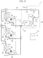
- the air conditioner (1) according to Embodiment 1 includes a refrigerant circuit (10) constituted of a single outdoor unit (20), three indoor units (30, 40, 50), and three BS units (60, 70, 80) connected by pipes.
- a refrigerant is circulated to perform a vapor compression refrigeration cycle.
- the outdoor unit (20) constitutes a heat-source unit, and includes a compressor (21), an outdoor heat exchanger (22), an outdoor expansion valve (23), a first three-way valve (24), and a second three-way valve (25).
- the compressor (21) constitutes a variable-volume inverter compressor.
- the outdoor heat exchanger (22) is a cross-fin heat exchanger and constitutes a heat-source heat exchanger of the present invention.
- the outdoor expansion valve (23) is an electronic expansion valve and constitutes a heat-source expansion valve of the present invention.
- the first three-way valve (24) and the second three-way valve (25) are constituted of four-way valves, respectively, in each of which one of four ports has been sealed. That is, each of the three-way valves (24, 25) has first to third ports.
- the first three-way valve (24) the first port is connected to a discharge side of the compressor (21), the second port is connected to the outdoor heat exchanger (22), and the third port is connected to a suction side of the compressor (21).
- the second three-way valve (25) the first port is connected to the discharge side of the compressor (21), the second port is connected to the BS units (60, 70, 80), and the third port is connected to the suction side of the compressor (21).
- Each f the three-way valves (24, 25) is switchable between a state in which the first port and the second port communicate with each other, and simultaneously, the third port is closed (a state indicated by a solid line in FIG. 1 ), and a state in which the second port and the third port communicate with each other, and simultaneously, the first port is closed (a state indicated by a broken line in FIG. 1 ).
- Each of the three-way valves (24, 25) constitutes a switching mechanism of the present invention.
- the outdoor unit (20) is provided with a plurality of pressure sensors (Ps1, Ps2, Ps3) for detecting pressure of the refrigerant.
- a high-pressure-side pressure sensor (Ps1) for detecting pressure of a high pressure refrigerant is provided on the discharge side of the compressor (21), and a low-pressure-side pressure sensor (Ps2) for detecting pressure of a low pressure refrigerant is provided on the suction side of the compressor (21).
- An on-liquid-pipe pressure sensor (Ps3) for detecting pressure of the refrigerant flowing in the liquid pipe (15) is provided on a liquid pipe (15) between the outdoor expansion valve (23) and the indoor units (30, 40, 50).
- the high-pressure-side pressure sensor (Ps1) and the on-liquid-pipe pressure sensor (Ps3) constitute a high-pressure-side pressure difference detection means of the present invention for detecting an index of pressure difference between the high pressure refrigerant on the discharge side of the compressor (21) and the refrigerant in the liquid pipe (15). Further, the on-liquid-pipe pressure sensor (Ps3) and the low-pressure-side pressure sensor (Ps2) constitute a low-pressure-side pressure difference detection means of the present invention for detecting an index of pressure difference between the refrigerant in the liquid pipe (15) and the low pressure refrigerant on the suction side of the compressor (21).
- the air conditioner (1) includes first to third indoor units (30, 40, 50).
- the indoor units (30, 40, 50) include first to third indoor heat exchangers (31, 41, 51) and first to third indoor expansion valves (32, 42, 52), respectively.
- the indoor heat exchangers (31, 41, 51) are cross-fin heat exchangers and constitute heat-using heat exchangers.
- the indoor heat exchangers (31, 41, 51) constitute "a plurality of heat exchangers" as claimed, which are connected in parallel to an end of the liquid pipe (15) at one ends thereof.
- the indoor expansion valves (32, 42, 52) are, for example, electronic expansion valves.
- the indoor expansion valves (32, 42, 52) constitute "a plurality of expansion valves" as claimed, each of which is provided on one end of the corresponding indoor heat exchanger (31, 41, 51 ).
- Each of the indoor units (30, 40, 50) includes a plurality of temperature sensors (Ts1, Ts2, Ts3, ...) for detecting the refrigerant's temperature.
- a first temperature sensor (Ts1) is arranged between an end of the first indoor heat exchanger (31) and the first indoor expansion valve (32), and a second temperature sensor (Ts2) is arranged at the other end of the first indoor heat exchanger (31).
- a third temperature sensor (Ts3) is arranged between an end of the second indoor heat exchanger (41) and the second indoor expansion valve (42), and a fourth temperature sensor (Ts4) is arranged at the other end of the second indoor heat exchanger (41).
- a fifth temperature sensor (Ts5) is arranged between an end of the third indoor heat exchanger (51) and the third indoor expansion valve (52), and a sixth temperature sensor (Ts6) is arranged at the other end of the third indoor heat exchanger (51).
- the air conditioner (1) includes first to third BS units (60, 70, 80) corresponding to the indoor units (30, 40, 50), respectively.
- Each of the BS units (60, 70, 80) includes a first branch pipe (61, 71, 81) and a second branch pipe (62, 72, 82) branched from the corresponding indoor unit (30, 40, 50).
- Each of the first branch pipes (61, 71, 81) and the second branch pipes (62, 72, 82) is provided with an open/close solenoid valve (SV)-1, SV-2, SV-3, ).
- the BS unit (60, 70, 80) constitutes a switching mechanism of the present invention which switches the flow path of the refrigerant by opening or closing the solenoid valve (SV1, SV-2, SV-3, ...) so that the other end of the corresponding indoor heat exchanger (31, 41, 51) is connected to the suction side or the discharge side of the compressor (21).
- the air conditioner (1) has a controller (16) which controls the three-way valves (24, 25), the solenoid valves (SV-1, SV-2, SV-3, ...), the compressor (21), and the like.
- the controller (16) receives signals detected by the above-described sensors.
- the controller (16) is provided with an expansion valve control means (17), which constitutes a feature of the present invention.
- the expansion valve control means (17) is configured to perform, in concurrent operation of the present invention described later, liquid pressure control operation by adjusting the degree of opening of the outdoor expansion valve (23) in response to pressure difference between the high pressure refrigerant and the refrigerant in the liquid pipe (15), and pressure difference between the refrigerant in the liquid pipe (15) and the low pressure refrigerant.
- Embodiment 1 An operation mechanism of the air conditioner (1) of Embodiment 1 will be described.
- the operation can be performed in various modes depending on the setting of the three-way valves (24, 25) and the open/close state of the solenoid valves (SV-1, SV-2, SV-3, ...) of the BS units (60, 70, 80). Among them, representative operation modes will be described below.
- each of the three-way valves (24, 25) is set to the state where the first port and the second port communicate with each other.
- the first solenoid valve (SV)-1), the third solenoid valve (SV-3), and the fifth solenoid valve (SV-5) are opened, and the second solenoid valve (SV-2), the fourth solenoid valve (SV-4), and the sixth solenoid valve (SV-6) are closed.
- closed solenoid valves are shown as black solenoid valves
- opened solenoid valves are shown as white solenoid valves.
- a refrigeration cycle is performed in which the outdoor heat exchanger (22) functions as an evaporator, and the indoor heat exchangers (31, 41, 51) function as condensers.
- heat exchangers serving as condensers are shown as dot-patterned heat exchangers
- heat exchangers serving as evaporators are shown as white heat exchangers.
- the refrigerant discharged from the compressor (21) passes through the second three-way valve (25), and is divided to flow into the first branch pipes (61, 71, 81) of the BS units (60, 70, 80), respectively. After passing through the BS units (60, 70, 80), the refrigerant is sent to the corresponding indoor units (30, 40, 50).
- the refrigerant flows into the first indoor heat exchanger (31), it dissipates heat into indoor air in the first indoor heat exchanger (31) and condenses. As a result, the room corresponding to the first indoor unit (30) is heated.
- the refrigerant condensed in the first indoor heat exchanger (31) passes through the first indoor expansion valve (32).
- the degree of opening of the first indoor expansion valve (32) is adjusted in response to the degree of subcooling of the refrigerant obtained by the first temperature sensor (Ts1), the second temperature sensor (Ts2), and the like.
- the degree of opening of the first indoor expansion valve (32) is increased so as to increase the flow rate of the refrigerant when a heating demand in the room is high, and the degree of subcooling of the refrigerant is high.
- the degree of opening of the first indoor expansion valve (32) is reduced so as to reduce the flow rate of the refrigerant when the heating demand in the room is low, and the degree of subcooling of the refrigerant is low.
- the refrigerant flows in the same manner as in the first indoor unit (30), and the corresponding rooms are heated.
- the refrigerants discharged from the indoor units (30, 40, 50) are joined into one in the liquid pipe (15).
- the refrigerant is reduced in pressure as it passes through the outdoor expansion valve (23) to become a low pressure refrigerant, and flows into the outdoor heat exchanger (22).
- the refrigerant absorbs heat from outdoor air and evaporates.
- the refrigerant evaporated in the outdoor heat exchanger (22) passes through the first three-way valve (24), and is sucked into the compressor (21) for recompression.
- each of the three-way valves (24, 25) is set to the state where the first port and the second port communicate with each other.
- the second solenoid valve (SV-2), the fourth solenoid valve (SV-4), and the sixth solenoid valve (SV-6) are opened, and the first solenoid valve (SV-1), the third solenoid valve (SV-3), and the fifth solenoid valve (SV-5) are closed.
- a refrigeration cycle is performed in which the outdoor heat exchanger (22) functions as a condenser, and the indoor heat exchangers (31, 41, 51) function as evaporators.
- the refrigerant discharged from the compressor (21) passes through the first three-way valve (24), and flows into the outdoor heat exchanger (22).
- the refrigerant dissipates heat into the outdoor air and condenses.
- the refrigerant condensed in the outdoor heat exchanger (22) passes through the fully opened outdoor expansion valve (23), flows through the liquid pipe (15), and is divided to flow into the indoor units (30, 40, 50).
- the refrigerant is reduced in pressure as it passes through the first indoor expansion valve (32) to become a low pressure refrigerant, and flows into the first indoor heat exchanger (31).
- the refrigerant absorbs heat from the indoor air and evaporates.
- the degree of opening of the first indoor expansion valve (32) is adjusted in response to the degree of superheating of the refrigerant obtained by the first temperature sensor (Ts1), the second temperature sensor (Ts2), and the like.
- the degree of opening of the first indoor expansion valve (32) is increased so as to increase the flow rate of the refrigerant when a cooling demand in the room is high, and the degree of superheating of the refrigerant is high.
- the degree of opening of the first indoor expansion valve (32) is reduced so as to reduce the flow rate of the refrigerant when the cooling demand in the room is low, and the degree of superheating of the refrigerant is low.
- the refrigerant flows in the same manner as in the first indoor unit (30), and the corresponding rooms are cooled.
- the refrigerants discharged from the indoor units (30, 40, 50) pass through the second branch pipes (62, 72, 82) of the BS units (60, 70, 80), respectively, and they are joined into one and sucked into the compressor (21) for recompression.
- the outdoor heat exchanger (22) functions as an evaporator or a condenser depending on the operating condition.
- the indoor heat exchanger in the room which demands the heating functions as a condenser, while the indoor heat exchanger in the room which demands the cooling functions as an evaporator.
- the outdoor heat exchanger (22) is used as a condenser
- at least one of the indoor heat exchangers (31, 41, 51) is used as a condenser
- the remaining indoor heat exchangers are used as evaporators.
- the first indoor unit (30) and the second indoor unit (40) perform heating of the corresponding rooms
- the third indoor unit (50) performs cooling of the corresponding room.
- each of the three-way valves (24, 25) is set to the state where the first port and the second port communicate with each other.
- the first solenoid valve (SV-1), the third solenoid valve (SV-3), and the sixth solenoid valve (SV)-6) are opened, and the second solenoid valve (SV-2), the fourth solenoid valve (SV-4), and the fifth solenoid valve (SV)-5) are closed.
- a refrigeration cycle is performed in which the outdoor heat exchanger (22), the first indoor heat exchanger (31), and the second indoor heat exchanger (41) function as condensers, and the third indoor heat exchanger (51) functions as an evaporator.
- the refrigerant discharged from the compressor (21) is divided to flow into the first three-way valve (24) and the second three-way valve (25).
- the refrigerant passed through the first three-way valve (24) condenses in the outdoor heat exchanger (22), passes through the outdoor expansion valve (23) opened to a predetermined degree, and then flows into the liquid pipe (15).
- the refrigerant passed through the second three-way valve (25) is divided to flow into the first BS unit (60) and the second BS unit (70).
- the refrigerant flowed out of the first BS unit (60) flows into the first indoor heat exchanger (31).
- the refrigerant dissipates heat into the indoor air and condenses.
- the room corresponding to the first indoor unit (30) is heated.
- the degree of opening of the first indoor expansion valve (32) is adjusted in response to the heating demand in the room, in the same manner as in the all heating operation described above.
- the refrigerant used in the first indoor unit (30) to heat the room flows into the liquid pipe (15).
- the refrigerant flowed out of the second BS unit (70) is used in the second indoor unit (40) to heat the room, and then flows into the liquid pipe (15).
- the refrigerants are joined into one in the liquid pipe (15), and guided to the third indoor unit (50).
- the refrigerant is reduced in pressure as it passes through the third indoor expansion valve (52) to become a low pressure refrigerant, and then flows into the third indoor heat exchanger (51).
- the refrigerant absorbs heat from the indoor air and evaporates. As a result, the room corresponding to the third indoor unit (50) is cooled.
- the refrigerant used in the third indoor unit (50) to cool the room passes through the third BS unit (80), and is sucked into the compressor (21) for recompression.
- the first indoor unit (30) performs heating of the corresponding room
- the second indoor unit (40) and the third indoor unit (50) perform cooling of the corresponding rooms.
- each of the three-way valves (24, 25) is set to the state where the first port and the second port communicate with each other.
- the first solenoid valve (SV-1), the fourth solenoid valve (SV-4), and the sixth solenoid valve (SV-6) are opened, and the second solenoid valve (SV-2), the third solenoid valve (SV-3), and the fifth solenoid valve (SV-5) are closed.
- a refrigeration cycle is performed in which the outdoor heat exchanger (22) and the first indoor heat exchanger (31) function as condensers, and the second indoor heat exchanger (41) and the third indoor heat exchanger (51) function as evaporators.
- the refrigerant discharged from the compressor (21) is divided to flow into the first three-way valve (24) and the second three-way valve (25).
- the refrigerant passed through the first three-way valve (24) condenses in the outdoor heat exchanger (22), passed through the outdoor expansion valve (23) opened. to a predetermined degree, and then flows into the liquid pipe (15).
- the refrigerant passed through the second three-way valve (25) is sent to the first indoor unit (30) through the first BS unit (60).
- the refrigerant condenses in the first indoor heat exchanger (31) to heat the room.
- the refrigerant used in the first indoor unit (30) to heat the room flows into the liquid pipe (15).
- the refrigerants are joined into one in the liquid pipe (15), and then divided to flow into the second indoor unit (40) and the third indoor unit (50).
- the refrigerant reduced in pressure by the second indoor expansion valve (42) evaporates in the second indoor heat exchanger (41) to cool the room.
- the refrigerant reduced in pressure by the third indoor expansion valve (52) evaporates in the third indoor heat exchanger (51) to cool the room.
- the refrigerants used in the indoor units (40, 50) to cool the rooms pass through the second BS unit (70) and the third BS unit (80), respectively, and they are joined into one and sucked into the compressor (21) for recompression.
- the heating capability may deteriorate due to the imbalance in refrigerant flow.
- the degree of opening of the indoor expansion valves (32, 42) is adjusted in response to the heating demand in the corresponding rooms.
- the reduced pressure difference between the high pressure refrigerant and the refrigerant in the liquid pipe (15) makes it difficult to send the refrigerant to the indoor unit which is away from the compressor (21) and experiences relatively high pressure loss in the refrigerant pipe (e.g., the second indoor unit (40)). That is, in this example, when the pressure difference between the high pressure refrigerant and the refrigerant in the liquid pipe (15) is reduced, a predetermined amount of the refrigerant can reliably be supplied to the first indoor unit (30) close to the compressor (21).
- the expansion valve control means (17) of the present embodiments performs the following liquid pressure control operation to prevent the deterioration of the heating capability due to the imbalance in refrigerant flow.
- the high-pressure-side pressure sensor (Ps1) detects the pressure of the high pressure refrigerant on the discharge side of the compressor (21).
- the on-liquid-pipe pressure sensor (Ps3) detects the pressure of the refrigerant flowing in the liquid pipe (15). Then, difference between the pressure detected by the high-pressure-side pressure sensor (Ps1) and the pressure detected by the on-liquid-pipe pressure sensor (Ps3) is obtained as pressure difference ⁇ P1 between the high pressure refrigerant and the refrigerant in the liquid pipe (15).
- the expansion valve control means (17) adjusts the degree of opening of the outdoor expansion valve (23) so that the pressure difference ⁇ P1 thus obtained becomes larger than a predetermined target value.
- the target value is variable depending on indoor temperature, outdoor temperature, operation states of the indoor units (30, 40, 50), operation frequency of the compressor (21), and the like. Further, the expansion valve control means (17) adjusts the degree of opening of the outdoor expansion valve (23) so that the pressure difference ⁇ P1 does not exceed a predetermined upper limit value. That is, the expansion valve control means (17) adjusts the degree of opening of the outdoor expansion valve (23) to keep the pressure difference ⁇ P1 within a predetermined target range.
- the expansion valve control means (17) reduces the degree of opening of the outdoor expansion valve (23). This reduces the pressure of the refrigerant in the liquid pipe (15), and the pressure difference ⁇ P1 becomes larger than the predetermined value.
- the pressure difference between the high pressure refrigerant and the refrigerant in the liquid pipe can be maintained at a certain level or higher.
- the refrigerant discharged from the compressor (21) sufficiently flows into the first indoor unit (30) and the second indoor unit (40), and the heating capability of the indoor units (30, 40) can reliably be maintained at a sufficient level.
- the outdoor expansion valve (23) is adjusted so that the pressure difference ⁇ P1 does not exceed the upper limit value. Specifically, the degree of opening of the outdoor expansion valve (23) is adjusted so as to prevent excessive reduction of the pressure of the refrigerant. This avoids excessive decrease in pressure of the refrigerant flowing in the liquid pipe (15).
- the heating capability and the cooling capability may deteriorate due to the imbalance in refrigerant flow.
- the heating capability of the first indoor heat exchanger (31) may become insufficient due to the imbalance in refrigerant flow between the outdoor heat exchanger (22) and the first indoor heat exchanger (31).
- the expansion valve control means (17) of the present embodiment performs the following liquid pressure control operation to prevent the deterioration of the cooling capability due to the imbalance in refrigerant flow.
- pressure difference ⁇ P1 between the high pressure refrigerant and the refrigerant in the liquid pipe is obtained by the high-pressure-side pressure sensor (Ps1) and the on-liquid-pipe pressure sensor (Ps3), in the same manner as shown in FIG. 4 .
- the low-pressure-side pressure sensor (Ps2) detects the pressure of the low pressure refrigerant on the suction side of the compressor (21). Then, difference between the pressure detected by the on-liquid-pipe pressure sensor (Ps3) and the pressure detected by the low-pressure-side pressure sensor (Ps2) is obtained as pressure difference ⁇ P2 between the refrigerant in the liquid pipe (15) and the low pressure refrigerant.
- the expansion valve control means (17) adjusts the degree of opening of the outdoor expansion valve (23) so that the pressure difference ⁇ P1 between the high pressure refrigerant and the refrigerant in the liquid pipe becomes larger than a predetermined target value, and that the pressure difference ⁇ P2 between the refrigerant in the liquid pipe and the low pressure refrigerant becomes larger than a predetermined target value.
- the target values are variable depending on indoor temperature, outdoor temperature, preset room temperature, operation states of the indoor units (30, 40, 50), operation frequency of the compressor (21), and the like.
- the expansion valve control means (17) reduces the degree of opening of the outdoor expansion valve (23). As a result, the pressure difference ⁇ P1 is maintained, and the imbalance in refrigerant flow between the outdoor heat exchanger (22) and the first indoor heat exchanger (31) is suppressed. This makes it possible to supply a sufficient amount of the refrigerant to the first indoor heat exchanger (31), and to solve the lack of heating capability of the first indoor unit (30).
- the expansion valve control means (17) increases the degree of opening of the outdoor expansion valve (23). As a result, the pressure of the refrigerant in the liquid pipe (15) is increased, and the pressure difference ⁇ P2 is maintained. This suppresses the imbalance in refrigerant flow between the second indoor heat exchanger (41) and the third indoor heat exchanger (51), and maintains the cooling capability of the indoor units (40, 50) at a sufficient level.
- the expansion valve control means (17) adjusts, in the above-described first concurrent operation, the degree of opening of the outdoor expansion valve (23) to maintain the pressure difference ⁇ P1 between the high pressure refrigerant and the refrigerant in the liquid pipe. Therefore, according to Embodiment 1, the imbalance in refrigerant flow between the outdoor heat exchanger (22) and the indoor heat exchangers (31, 41) serving as condensers can be prevented, and a sufficient amount of the refrigerant can reliably be supplied to the indoor heat exchangers (31, 41). This allows prevention of the deterioration in heating capability of the indoor units (30, 40), and improvement in reliability of the air conditioner (1).
- the expansion valve control means (17) adjusts the degree of opening of the outdoor expansion valve (23) to maintain the pressure difference ⁇ P1 between the high pressure refrigerant and the refrigerant in the liquid pipe, and to maintain the pressure difference ⁇ P2 between the refrigerant in the liquid pipe and the low pressure refrigerant. Therefore, according to Embodiment 1, the imbalance in refrigerant flow between the outdoor heat exchanger (22) and the indoor heat exchanger (31) serving as a condenser can be prevented, and simultaneously, the imbalance in refrigerant flow between the indoor heat exchangers (41, 51) serving as evaporators can also be prevented. This allows prevention of the deterioration in heating and cooling capability of the indoor units (30, 40, 50), and improvement in reliability of the air conditioner (1).
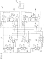
- a refrigeration system according to Embodiment 2 of the present invention is configured by adding a plurality of outdoor units (20, 90) to the air conditioner of Embodiment 1.
- a plurality of outdoor units (20, 90) to the air conditioner of Embodiment 1.
- an air conditioner (1) of Embodiment 2 includes a first outdoor unit (20) and a second outdoor unit (90).
- the outdoor units (20, 90) are configured in the same manner as the outdoor unit of Embodiment 1. That is, the first outdoor unit (20) includes a first compressor (21), a first outdoor heat exchanger (22), a first outdoor expansion valve (23), a first three-way valve (24), a second three-way valve (25), a first high-pressure-side pressure sensor (Ps1), a first low-pressure-side pressure sensor (Ps2), and a first on-liquid-pipe pressure sensor (Ps3).
- the second outdoor unit (90) includes a second compressor (91), a second outdoor heat exchanger (92), a second outdoor expansion valve (93), a third three-way valve (94), a fourth three-way valve (95), a second high-pressure-side pressure sensor (Ps4), a second low-pressure-side pressure sensor (Ps5), and a second on-liquid-pipe pressure sensor (Ps6).
- the air conditioner (1) of Embodiment 2 is also provided with an expansion valve control means (17) which performs liquid pressure control operation in the above-described concurrent operation by adjusting the degree of opening of the outdoor expansion valves (23, 93).
- the degree of opening of the outdoor expansion valves (23, 93) corresponding to the outdoor heat exchangers (20, 90) serving as condensers is adjusted in response to pressure difference between the high pressure refrigerant and the refrigerant in the liquid pipe, and pressure difference between the refrigerant in the liquid pipe and the low pressure refrigerant.
- the liquid pressure control operation of the present invention can also be applied to the following concurrent operation.
- all the indoor units (30, 40, 50) perform heating, and one outdoor heat exchanger (92) is used as an evaporator.
- a refrigeration cycle is performed in which the first outdoor heat exchanger (22) functions as a condenser, three heat exchangers (the first to third indoor heat exchangers (31, 41, 51)) among the plurality of heat exchangers (31, 41, 51, 92) function as condensers, and the remaining heat exchanger (the second outdoor heat exchanger (92)) functions as an evaporator.
- the expansion valve control means (17) adjusts the degree of opening of the first outdoor expansion valve (23) so that pressure difference ⁇ P1 between the high pressure refrigerant and the refrigerant in the liquid pipe obtained by the first high-pressure-side pressure sensor (Ps1) and the first on-liquid-pipe pressure sensor (Ps3) becomes larger than a predetermined target value.
- a sufficient amount of the refrigerant can be sent to the indoor heat exchangers (31, 41, 51), and the heating capability of the indoor units (30, 40, 50) can reliably be maintained at a sufficient level.
- one or more indoor units (30, 40) perform heating, and simultaneously, the remaining indoor unit (50) performs cooling, and one outdoor heat exchanger (92) functions as an evaporator.
- a refrigeration cycle is performed in which the first outdoor heat exchanger (22) functions as a condenser, two heat exchangers (the third indoor heat exchanger (51) and the second outdoor heat exchanger (92)) among the plurality of heat exchangers (31, 41, 51, 92) function as evaporators, and the remaining heat exchangers (the first indoor heat exchanger (31) and the second indoor heat exchanger (41)) function as condensers.
- the expansion valve control means (17) adjusts the degree of opening of the first outdoor expansion valve (23) so that the pressure difference ⁇ P1 between the high pressure refrigerant and the refrigerant in the liquid pipe obtained by the first high-pressure-side pressure sensor (Ps1) and the first on-liquid-pipe pressure sensor (Ps3) becomes larger than a predetermined target value.
- the imbalance in refrigerant flow may also occur between the second outdoor heat exchanger (92) and the third indoor heat exchanger (51) for the above-described reason, and the cooling capability of the third indoor unit (50) may possibly deteriorate.
- the expansion valve control means (17) adjusts the degree of opening of the first outdoor expansion valve (23) so that pressure difference ⁇ P2 between the refrigerant in the liquid pipe and the low pressure refrigerant obtained by the first on-liquid-pipe pressure sensor (Ps3) and the low-pressure-side pressure sensor (Ps2) becomes larger than a predetermined target value.
- a sufficient amount of the refrigerant can be sent to the third indoor heat exchanger (51), and the cooling capability of the third indoor unit (50) can reliably be maintained at a sufficient level.
- Embodiments 1 and 2 described above may be modified in the following manner.
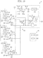
- the high-pressure-side pressure sensor (Ps1) and an on-liquid-pipe temperature sensor (Ts8) may be used as shown in FIG. 9 .
- the high-pressure-side pressure sensor (Ps1) constitutes a condensation temperature detection means which detects condensation temperature of the refrigerant in the outdoor heat exchanger (22) in the concurrent operation.
- the condensation temperature in the outdoor heat exchanger (22) can be obtained by calculating saturation temperature corresponding to the pressure detected by the high-pressure-side pressure sensor (Ps1).
- the condensation temperature in the outdoor heat exchanger (22) may be obtained by directly detecting the temperature of the refrigerant in a heat transfer tube of the outdoor heat exchanger (22).
- the refrigerant passed through the outdoor expansion valve (23) is guided to the liquid pipe (15). Since this refrigerant is reduced to a predetermined pressure by the outdoor expansion valve (23), it is in a vapor-liquid two phase.
- the on-liquid-pipe temperature sensor (Ts8) detects the temperature of the vapor-liquid two phase refrigerant in the liquid pipe (15).
- the condensation temperature in the outdoor heat exchanger (22) varies depending on change in pressure of the high pressure refrigerant. Therefore, it will be an index of the pressure of the high pressure refrigerant.
- the temperature of the refrigerant in the liquid pipe (15) varies depending on change in pressure of the refrigerant in the liquid pipe (15). Therefore, it will be an index of the pressure of the refrigerant in the liquid pipe (15). Accordingly, pressure difference between the high pressure refrigerant and the refrigerant in the liquid pipe can be grasped by obtaining difference ⁇ T1 between the condensation temperature and the temperature of the refrigerant in the liquid pipe (15).
- the expansion valve control means (17) adjusts the degree of opening of the outdoor expansion valve (23) so that the temperature difference ⁇ T1 becomes larger than a predetermined target value. This maintains the pressure difference between the high pressure refrigerant and the refrigerant in the liquid pipe, and prevents the above-described imbalance in refrigerants flow.
- the on-liquid-pipe temperature sensor (Ts8), and the first temperature sensor (Ts1), the third temperature sensor (Ts3), and the fifth temperature sensors (Ts5) provided on the indoor units (30, 40, 50) may be used.
- the refrigerant reduced in pressure by the indoor expansion valves (42, 52) to become a low pressure refrigerant flows into the indoor heat exchangers (41, 51) of the second and third indoor units (40, 50) which perform cooling, respectively.
- evaporation temperature of the refrigerant in the second indoor heat exchanger (41) can be obtained by detecting the temperature of the refrigerant flowing into the second indoor heat exchanger (41) by the third temperature sensor (Ts3).
- evaporation temperature of the refrigerant in the third indoor heat exchanger (51) can be obtained by detecting the temperature of the refrigerant flowing into the third indoor heat exchanger (51) by the fifth temperature sensor (Ts5).
- the first temperature sensor (Ts1), the third temperature sensor (Ts3), and the fifth temperature sensor (Ts5) constitute an evaporation temperature detection means which detects the evaporation temperature of the refrigerant in the heat exchanger serving as an evaporator in the concurrent operation.
- the low-pressure-side pressure sensor (Ps2) described in Embodiments 1 and 2 may be used.
- the evaporation temperature in the heat exchanger serving as an evaporator may be obtained by calculating saturation temperature corresponding to the pressure detected by the low-pressure-side pressure sensor (Ps2).
- the evaporation temperature of the refrigerant in the indoor heat exchangers (41, 51) may vary depending on change in pressure of the low pressure refrigerant. Therefore, it will be an index of the pressure of the low pressure refrigerant. Accordingly, pressure difference between the refrigerant in the liquid pipe and the low pressure refrigerant can be grasped by obtaining difference ⁇ T2 between the temperature of the refrigerant in the liquid pipe (15) and the evaporation temperature.
- the expansion valve control means (17) adjusts the degree of opening of the outdoor expansion valve (23) so that the temperature difference ⁇ T2 becomes larger than a predetermined target value. This maintains the pressure difference between the refrigerant in the liquid pipe and the low pressure refrigerant, and prevents the above-described imbalance in refrigerant flow.
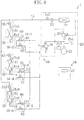
- a subcooling heat exchanger (28) may be added to the outdoor unit (20).
- an injection pipe (19) branched from the liquid pipe (15) and connected to the suction side of the compressor (21) is provided.
- the injection pipe (19) has a pressure reducing valve (19a), whose degree of opening is adjustable.
- the subcooling heat exchanger (28) is connected to both of the liquid pipe (15) and the injection pipe (19) downstream of the pressure reducing valve (19a). That is, the subcooling heat exchanger (28) allows, in the concurrent operation, heat exchange between the refrigerant in the liquid pipe (15) and the refrigerant in the injection pipe (19) after passing through the pressure reducing valve (19a).
- the subcooling heat exchanger (28) constitutes a cooling means which cools the refrigerant that passed through the outdoor expansion valve (23) in the concurrent operation.
- the cooling means other cooling means than that described in this modified example may be used.
- the liquid pipe (15) is further provided with a first on-liquid-pipe temperature sensor (Ts7) provided on the inlet side of the subcooling heat exchanger (28) in the concurrent operation, and a second on-liquid-pipe temperature sensor (Ts8) provided on the outlet side of the subcooling heat exchanger (28).
- the on-liquid-pipe temperature sensors (Ts7, Ts8) constitute a temperature difference detection means which detects temperature difference between the refrigerant flowing into the subcooling heat exchanger (28) and the refrigerant flowing out of the subcooling heat exchanger (28).
- a controller (16) includes an injection amount control means (18) which adjusts the degree of opening of the pressure reducing valve (19a) so that the difference between the temperatures detected by the on-liquid-pipe temperature sensors (Ts7, Ts8) becomes larger than a predetermined value in the concurrent operation.
- the degree of opening of the pressure reducing valve (19a) is adjusted in the above-described concurrent operation so that the refrigerant flowing from the liquid pipe (15) to the low pressure side does not become a vapor-liquid two phase refrigerant.
- the expansion valve control means (17) adjusts the degree of opening of the outdoor expansion valve (23) within a predetermined target range, the refrigerant reduced in pressure by the outdoor expansion valve (23) will be the vapor-liquid two phase refrigerant.
- the refrigerant flowing in the liquid pipe (15) is cooled in the subcooling heat exchanger (28) to prevent the noise generation.
- the refrigerant condensed in the outdoor heat exchanger (22) and reduced in pressure by the outdoor expansion valve (23) becomes the vapor-liquid two phase refrigerant, and flows into the liquid pipe (15). Part of this refrigerant flows into the injection pipe (19).
- the refrigerant flowed into the injection pipe (19) is reduced in pressure by the pressure reducing valve (19a), and passes through the subcooling heat exchanger (28). In the subcooling heat exchanger (28), the vapor-liquid two phase refrigerant in the liquid pipe (15) and the low pressure refrigerant in the injection pipe (19) exchange heat.
- the refrigerant in the injection pipe (19) absorbs heat from the refrigerant in the liquid pipe (15) and evaporates. As a result, the refrigerant in the liquid pipe (15) is cooled.
- the degree of opening of the pressure reducing valve (19a) in the injection pipe (19) is adjusted so as to maintain the temperature difference between the refrigerant in the liquid pipe (15) before passing through the subcooling heat exchanger (28) and the refrigerant which passed. through the subcooling heat exchanger (28), i.e., to maintain a predetermined degree of subcooling.
- the refrigerant in the liquid pipe (15) which passed through the subcooling heat exchanger (28) will reliably become a liquid refrigerant.
- the liquid refrigerant thus obtained is sent to the low pressure third indoor unit (50).
- the liquid refrigerant passes through the third indoor expansion valve (52). Therefore, noise generation by the refrigerant passing through the expansion valve is reduced as compared with the noise generation by the vapor-liquid two phase refrigerant.
- the air conditioner may include a larger number of indoor and outdoor units.
- the present invention relates to a refrigeration system including a refrigerant circuit having a plurality of heat exchangers, and is particularly useful as measures to cope with an imbalance in refrigerant flow between the heat exchangers.
Landscapes
- Engineering & Computer Science (AREA)
- Physics & Mathematics (AREA)
- Mechanical Engineering (AREA)
- Thermal Sciences (AREA)
- General Engineering & Computer Science (AREA)
- Air Conditioning Control Device (AREA)
- Compression-Type Refrigeration Machines With Reversible Cycles (AREA)
Applications Claiming Priority (2)
| Application Number | Priority Date | Filing Date | Title |
|---|---|---|---|
| JP2006326474A JP4389927B2 (ja) | 2006-12-04 | 2006-12-04 | 空気調和装置 |
| PCT/JP2007/072918 WO2008069066A1 (ja) | 2006-12-04 | 2007-11-28 | 冷凍装置 |
Publications (3)
| Publication Number | Publication Date |
|---|---|
| EP2090849A1 EP2090849A1 (en) | 2009-08-19 |
| EP2090849A4 EP2090849A4 (en) | 2013-05-01 |
| EP2090849B1 true EP2090849B1 (en) | 2017-09-27 |
Family
ID=39491967
Family Applications (1)
| Application Number | Title | Priority Date | Filing Date |
|---|---|---|---|
| EP07832640.2A Active EP2090849B1 (en) | 2006-12-04 | 2007-11-28 | Refrigeration device |
Country Status (8)
| Country | Link |
|---|---|
| US (1) | US8047011B2 (zh) |
| EP (1) | EP2090849B1 (zh) |
| JP (1) | JP4389927B2 (zh) |
| KR (1) | KR101096822B1 (zh) |
| CN (1) | CN101535738B (zh) |
| AU (1) | AU2007330102B2 (zh) |
| ES (1) | ES2644798T3 (zh) |
| WO (1) | WO2008069066A1 (zh) |
Families Citing this family (33)
| Publication number | Priority date | Publication date | Assignee | Title |
|---|---|---|---|---|
| EP1857363A1 (fr) | 2006-05-19 | 2007-11-21 | Lebrun Nimy | Dispositif de régulation de température |
| JP4285583B2 (ja) * | 2007-05-30 | 2009-06-24 | ダイキン工業株式会社 | 空気調和装置 |
| JP4541428B2 (ja) | 2008-05-28 | 2010-09-08 | ヒロセ電機株式会社 | 平型導体用電気コネクタ |
| JP5377041B2 (ja) * | 2009-04-09 | 2013-12-25 | 日立アプライアンス株式会社 | 冷凍サイクル装置 |
| US20110054701A1 (en) * | 2009-08-27 | 2011-03-03 | Blueair Controls, Inc. | Energy saving method and system for climate control system |
| WO2011080800A1 (ja) * | 2009-12-28 | 2011-07-07 | ダイキン工業株式会社 | ヒートポンプシステム |
| WO2012008148A1 (ja) * | 2010-07-13 | 2012-01-19 | ダイキン工業株式会社 | 冷媒流路切換ユニット |
| JP5445494B2 (ja) * | 2011-03-17 | 2014-03-19 | 株式会社富士通ゼネラル | 空気調和装置 |
| JP5573741B2 (ja) * | 2011-03-18 | 2014-08-20 | 株式会社富士通ゼネラル | 空気調和装置 |
| KR101910658B1 (ko) * | 2011-07-18 | 2018-10-23 | 삼성전자주식회사 | 멀티형 공기조화기 |
| CN103917834B (zh) * | 2011-11-07 | 2015-12-16 | 三菱电机株式会社 | 空气调节装置 |
| JP6079061B2 (ja) * | 2012-02-06 | 2017-02-15 | ダイキン工業株式会社 | 冷凍装置 |
| CN104246395B (zh) | 2012-03-15 | 2016-08-24 | 三菱电机株式会社 | 制冷循环装置 |
| EP2833086B1 (en) * | 2012-03-27 | 2017-06-21 | Mitsubishi Electric Corporation | Air-conditioning apparatus |
| US10233788B1 (en) * | 2012-04-10 | 2019-03-19 | Neil Tice | Method and apparatus utilizing thermally conductive pumps for conversion of thermal energy to mechanical energy |
| KR101678324B1 (ko) | 2012-08-27 | 2016-11-21 | 다이킨 고교 가부시키가이샤 | 냉동장치 |
| JP6029382B2 (ja) * | 2012-08-27 | 2016-11-24 | 三菱重工業株式会社 | 空気調和装置 |
| WO2014084343A1 (ja) * | 2012-11-30 | 2014-06-05 | サンデン株式会社 | 車両用空気調和装置 |
| WO2014118953A1 (ja) * | 2013-01-31 | 2014-08-07 | 三菱電機株式会社 | 冷凍サイクル装置、及び、冷凍サイクル装置の制御方法 |
| KR20150012498A (ko) * | 2013-07-25 | 2015-02-04 | 삼성전자주식회사 | 히트 펌프 및 유로 전환 장치 |
| JP5907212B2 (ja) * | 2014-05-28 | 2016-04-26 | ダイキン工業株式会社 | 熱回収型冷凍装置 |
| JP6138364B2 (ja) * | 2014-05-30 | 2017-05-31 | 三菱電機株式会社 | 空気調和機 |
| JP6248878B2 (ja) * | 2014-09-18 | 2017-12-20 | 株式会社富士通ゼネラル | 空気調和装置 |
| CN104776659A (zh) * | 2015-04-14 | 2015-07-15 | 四川长虹空调有限公司 | 多联机制冷剂平衡的控制方法及实现该方法的空调系统 |
| EP3348934B1 (en) * | 2015-09-11 | 2021-10-27 | Hitachi-Johnson Controls Air Conditioning, Inc. | Air conditioner |
| CN107356012A (zh) | 2016-05-09 | 2017-11-17 | 开利公司 | 热泵系统及其控制方法 |
| JP6323508B2 (ja) * | 2016-08-04 | 2018-05-16 | ダイキン工業株式会社 | 冷凍装置 |
| CN107676920B (zh) * | 2017-08-24 | 2021-05-25 | 青岛海尔空调电子有限公司 | 一种冷水机组控制方法及系统 |
| CN111919073B (zh) * | 2018-03-30 | 2023-06-27 | 大金工业株式会社 | 制冷装置 |
| EP3792570A4 (en) * | 2018-05-11 | 2021-04-21 | Mitsubishi Electric Corporation | REFRIGERATION CYCLE SYSTEM |
| US11835270B1 (en) * | 2018-06-22 | 2023-12-05 | Booz Allen Hamilton Inc. | Thermal management systems |
| CN109855252B (zh) * | 2019-02-14 | 2022-02-22 | 青岛海尔空调电子有限公司 | 多联机空调系统的冷媒控制方法 |
| US11731490B2 (en) * | 2021-07-14 | 2023-08-22 | GM Global Technology Operations LLC | Refrigerant system diagnostics |
Family Cites Families (19)
| Publication number | Priority date | Publication date | Assignee | Title |
|---|---|---|---|---|
| US4651535A (en) * | 1984-08-08 | 1987-03-24 | Alsenz Richard H | Pulse controlled solenoid valve |
| US4771610A (en) * | 1986-06-06 | 1988-09-20 | Mitsubishi Denki Kabushiki Kaisha | Multiroom air conditioner |
| US4833893A (en) * | 1986-07-11 | 1989-05-30 | Kabushiki Kaisha Toshiba | Refrigerating system incorporating a heat accumulator and method of operating the same |
| US4841734A (en) * | 1987-11-12 | 1989-06-27 | Eaton Corporation | Indicating refrigerant liquid saturation point |
| JPH0213765A (ja) * | 1988-06-30 | 1990-01-18 | Toshiba Corp | 冷凍サイクル装置 |
| EP0431491A1 (en) * | 1989-12-06 | 1991-06-12 | Kabushiki Kaisha Toshiba | Heat pump type heating apparatus and control method thereof |
| JP2848691B2 (ja) * | 1990-11-15 | 1999-01-20 | 株式会社東芝 | 空気調和機 |
| US5109677A (en) * | 1991-02-21 | 1992-05-05 | Gary Phillippe | Supplemental heat exchanger system for heat pump |
| JP2968392B2 (ja) | 1992-05-29 | 1999-10-25 | 株式会社日立製作所 | 空気調和機 |
| US5461876A (en) * | 1994-06-29 | 1995-10-31 | Dressler; William E. | Combined ambient-air and earth exchange heat pump system |
| US5937665A (en) * | 1998-01-15 | 1999-08-17 | Geofurnace Systems, Inc. | Geothermal subcircuit for air conditioning unit |
| JP3266116B2 (ja) | 1998-11-11 | 2002-03-18 | ダイキン工業株式会社 | 空気調和装置 |
| JP4032634B2 (ja) * | 2000-11-13 | 2008-01-16 | ダイキン工業株式会社 | 空気調和装置 |
| KR100614364B1 (ko) * | 2002-08-02 | 2006-08-22 | 다이킨 고교 가부시키가이샤 | 냉동 장치 |
| US7159409B2 (en) * | 2004-03-01 | 2007-01-09 | Tecumseh Products Company | Method and apparatus for controlling the load placed on a compressor |
| KR100888384B1 (ko) * | 2004-05-28 | 2009-03-13 | 요크 인터내셔널 코포레이션 | 이코노마이저 회로 제어 시스템 및 방법 |
| KR20060030761A (ko) * | 2004-10-06 | 2006-04-11 | 삼성전자주식회사 | 다실형 공기조화 시스템 및 그 제어방법 |
| JP2006250479A (ja) * | 2005-03-14 | 2006-09-21 | Fujitsu General Ltd | 空気調和機 |
| US7213407B2 (en) * | 2005-04-12 | 2007-05-08 | Lung Tan Hu | Wide temperature range heat pump |
-
2006
- 2006-12-04 JP JP2006326474A patent/JP4389927B2/ja active Active
-
2007
- 2007-11-28 AU AU2007330102A patent/AU2007330102B2/en active Active
- 2007-11-28 WO PCT/JP2007/072918 patent/WO2008069066A1/ja active Application Filing
- 2007-11-28 CN CN2007800410131A patent/CN101535738B/zh active Active
- 2007-11-28 ES ES07832640.2T patent/ES2644798T3/es active Active
- 2007-11-28 US US12/515,957 patent/US8047011B2/en active Active
- 2007-11-28 EP EP07832640.2A patent/EP2090849B1/en active Active
- 2007-11-28 KR KR1020097011221A patent/KR101096822B1/ko active IP Right Grant
Non-Patent Citations (1)
| Title |
|---|
| None * |
Also Published As
| Publication number | Publication date |
|---|---|
| JP2008138954A (ja) | 2008-06-19 |
| WO2008069066A1 (ja) | 2008-06-12 |
| US8047011B2 (en) | 2011-11-01 |
| CN101535738A (zh) | 2009-09-16 |
| AU2007330102A1 (en) | 2008-06-12 |
| US20100043467A1 (en) | 2010-02-25 |
| AU2007330102B2 (en) | 2010-10-21 |
| KR20090085659A (ko) | 2009-08-07 |
| EP2090849A1 (en) | 2009-08-19 |
| CN101535738B (zh) | 2011-02-16 |
| EP2090849A4 (en) | 2013-05-01 |
| JP4389927B2 (ja) | 2009-12-24 |
| ES2644798T3 (es) | 2017-11-30 |
| KR101096822B1 (ko) | 2011-12-22 |
Similar Documents
| Publication | Publication Date | Title |
|---|---|---|
| EP2090849B1 (en) | Refrigeration device | |
| CN108027179B (zh) | 空气调节机 | |
| US9683768B2 (en) | Air-conditioning apparatus | |
| US11268743B2 (en) | Air-conditioning apparatus having heating-defrosting operation mode | |
| US9506674B2 (en) | Air conditioner including a bypass pipeline for a defrosting operation | |
| EP2128541B1 (en) | Refrigeration device | |
| KR100188860B1 (ko) | 냉동장치 | |
| KR101421908B1 (ko) | 공기 조화 장치 | |
| US8307668B2 (en) | Air conditioner | |
| EP2375188B1 (en) | Air conditioner | |
| US20080282728A1 (en) | Refrigerating Apparatus | |
| WO2017138108A1 (ja) | 空気調和装置 | |
| EP3236168B1 (en) | Air conditioning device | |
| JP5855284B2 (ja) | 空気調和装置 | |
| JP6448780B2 (ja) | 空気調和装置 | |
| JP2987951B2 (ja) | 空気調和装置の運転制御装置 | |
| GB2579961A (en) | Air-conditioning apparatus | |
| JP5537906B2 (ja) | 空気調和装置 | |
| GB2567332A (en) | Air conditioning device | |
| JP7378671B1 (ja) | 空気調和装置 | |
| EP1235043A1 (en) | Refrigerating device |
Legal Events
| Date | Code | Title | Description |
|---|---|---|---|
| PUAI | Public reference made under article 153(3) epc to a published international application that has entered the european phase |
Free format text: ORIGINAL CODE: 0009012 |
|
| 17P | Request for examination filed |
Effective date: 20090507 |
|
| AK | Designated contracting states |
Kind code of ref document: A1 Designated state(s): AT BE BG CH CY CZ DE DK EE ES FI FR GB GR HU IE IS IT LI LT LU LV MC MT NL PL PT RO SE SI SK TR |
|
| DAX | Request for extension of the european patent (deleted) | ||
| A4 | Supplementary search report drawn up and despatched |
Effective date: 20130404 |
|
| RIC1 | Information provided on ipc code assigned before grant |
Ipc: F25B 13/00 20060101ALI20130327BHEP Ipc: F24F 11/02 20060101ALI20130327BHEP Ipc: F25B 29/00 20060101ALI20130327BHEP Ipc: F25B 1/00 20060101AFI20130327BHEP |
|
| GRAP | Despatch of communication of intention to grant a patent |
Free format text: ORIGINAL CODE: EPIDOSNIGR1 |
|
| INTG | Intention to grant announced |
Effective date: 20170608 |
|
| GRAS | Grant fee paid |
Free format text: ORIGINAL CODE: EPIDOSNIGR3 |
|
| GRAA | (expected) grant |
Free format text: ORIGINAL CODE: 0009210 |
|
| AK | Designated contracting states |
Kind code of ref document: B1 Designated state(s): AT BE BG CH CY CZ DE DK EE ES FI FR GB GR HU IE IS IT LI LT LU LV MC MT NL PL PT RO SE SI SK TR |
|
| REG | Reference to a national code |
Ref country code: GB Ref legal event code: FG4D |
|
| REG | Reference to a national code |
Ref country code: CH Ref legal event code: EP |
|
| REG | Reference to a national code |
Ref country code: AT Ref legal event code: REF Ref document number: 932330 Country of ref document: AT Kind code of ref document: T Effective date: 20171015 |
|
| REG | Reference to a national code |
Ref country code: IE Ref legal event code: FG4D |
|
| REG | Reference to a national code |
Ref country code: DE Ref legal event code: R096 Ref document number: 602007052510 Country of ref document: DE |
|
| REG | Reference to a national code |
Ref country code: FR Ref legal event code: PLFP Year of fee payment: 11 |
|
| REG | Reference to a national code |
Ref country code: ES Ref legal event code: FG2A Ref document number: 2644798 Country of ref document: ES Kind code of ref document: T3 Effective date: 20171130 |
|
| PG25 | Lapsed in a contracting state [announced via postgrant information from national office to epo] |
Ref country code: SE Free format text: LAPSE BECAUSE OF FAILURE TO SUBMIT A TRANSLATION OF THE DESCRIPTION OR TO PAY THE FEE WITHIN THE PRESCRIBED TIME-LIMIT Effective date: 20170927 Ref country code: FI Free format text: LAPSE BECAUSE OF FAILURE TO SUBMIT A TRANSLATION OF THE DESCRIPTION OR TO PAY THE FEE WITHIN THE PRESCRIBED TIME-LIMIT Effective date: 20170927 Ref country code: LT Free format text: LAPSE BECAUSE OF FAILURE TO SUBMIT A TRANSLATION OF THE DESCRIPTION OR TO PAY THE FEE WITHIN THE PRESCRIBED TIME-LIMIT Effective date: 20170927 |
|
| REG | Reference to a national code |
Ref country code: NL Ref legal event code: MP Effective date: 20170927 |
|
| REG | Reference to a national code |
Ref country code: LT Ref legal event code: MG4D |
|
| REG | Reference to a national code |
Ref country code: AT Ref legal event code: MK05 Ref document number: 932330 Country of ref document: AT Kind code of ref document: T Effective date: 20170927 |
|
| PG25 | Lapsed in a contracting state [announced via postgrant information from national office to epo] |
Ref country code: GR Free format text: LAPSE BECAUSE OF FAILURE TO SUBMIT A TRANSLATION OF THE DESCRIPTION OR TO PAY THE FEE WITHIN THE PRESCRIBED TIME-LIMIT Effective date: 20171228 Ref country code: LV Free format text: LAPSE BECAUSE OF FAILURE TO SUBMIT A TRANSLATION OF THE DESCRIPTION OR TO PAY THE FEE WITHIN THE PRESCRIBED TIME-LIMIT Effective date: 20170927 Ref country code: BG Free format text: LAPSE BECAUSE OF FAILURE TO SUBMIT A TRANSLATION OF THE DESCRIPTION OR TO PAY THE FEE WITHIN THE PRESCRIBED TIME-LIMIT Effective date: 20171227 |
|
| PG25 | Lapsed in a contracting state [announced via postgrant information from national office to epo] |
Ref country code: NL Free format text: LAPSE BECAUSE OF FAILURE TO SUBMIT A TRANSLATION OF THE DESCRIPTION OR TO PAY THE FEE WITHIN THE PRESCRIBED TIME-LIMIT Effective date: 20170927 |
|
| PG25 | Lapsed in a contracting state [announced via postgrant information from national office to epo] |
Ref country code: RO Free format text: LAPSE BECAUSE OF FAILURE TO SUBMIT A TRANSLATION OF THE DESCRIPTION OR TO PAY THE FEE WITHIN THE PRESCRIBED TIME-LIMIT Effective date: 20170927 Ref country code: CZ Free format text: LAPSE BECAUSE OF FAILURE TO SUBMIT A TRANSLATION OF THE DESCRIPTION OR TO PAY THE FEE WITHIN THE PRESCRIBED TIME-LIMIT Effective date: 20170927 |
|
| PG25 | Lapsed in a contracting state [announced via postgrant information from national office to epo] |
Ref country code: EE Free format text: LAPSE BECAUSE OF FAILURE TO SUBMIT A TRANSLATION OF THE DESCRIPTION OR TO PAY THE FEE WITHIN THE PRESCRIBED TIME-LIMIT Effective date: 20170927 Ref country code: IS Free format text: LAPSE BECAUSE OF FAILURE TO SUBMIT A TRANSLATION OF THE DESCRIPTION OR TO PAY THE FEE WITHIN THE PRESCRIBED TIME-LIMIT Effective date: 20180127 Ref country code: AT Free format text: LAPSE BECAUSE OF FAILURE TO SUBMIT A TRANSLATION OF THE DESCRIPTION OR TO PAY THE FEE WITHIN THE PRESCRIBED TIME-LIMIT Effective date: 20170927 Ref country code: SK Free format text: LAPSE BECAUSE OF FAILURE TO SUBMIT A TRANSLATION OF THE DESCRIPTION OR TO PAY THE FEE WITHIN THE PRESCRIBED TIME-LIMIT Effective date: 20170927 |
|
| REG | Reference to a national code |
Ref country code: DE Ref legal event code: R097 Ref document number: 602007052510 Country of ref document: DE |
|
| PG25 | Lapsed in a contracting state [announced via postgrant information from national office to epo] |
Ref country code: MC Free format text: LAPSE BECAUSE OF FAILURE TO SUBMIT A TRANSLATION OF THE DESCRIPTION OR TO PAY THE FEE WITHIN THE PRESCRIBED TIME-LIMIT Effective date: 20170927 |
|
| PG25 | Lapsed in a contracting state [announced via postgrant information from national office to epo] |
Ref country code: DK Free format text: LAPSE BECAUSE OF FAILURE TO SUBMIT A TRANSLATION OF THE DESCRIPTION OR TO PAY THE FEE WITHIN THE PRESCRIBED TIME-LIMIT Effective date: 20170927 Ref country code: CH Free format text: LAPSE BECAUSE OF NON-PAYMENT OF DUE FEES Effective date: 20171130 Ref country code: LI Free format text: LAPSE BECAUSE OF NON-PAYMENT OF DUE FEES Effective date: 20171130 |
|
| PLBE | No opposition filed within time limit |
Free format text: ORIGINAL CODE: 0009261 |
|
| STAA | Information on the status of an ep patent application or granted ep patent |
Free format text: STATUS: NO OPPOSITION FILED WITHIN TIME LIMIT |
|
| PG25 | Lapsed in a contracting state [announced via postgrant information from national office to epo] |
Ref country code: LU Free format text: LAPSE BECAUSE OF NON-PAYMENT OF DUE FEES Effective date: 20171128 Ref country code: PL Free format text: LAPSE BECAUSE OF FAILURE TO SUBMIT A TRANSLATION OF THE DESCRIPTION OR TO PAY THE FEE WITHIN THE PRESCRIBED TIME-LIMIT Effective date: 20170927 |
|
| REG | Reference to a national code |
Ref country code: BE Ref legal event code: MM Effective date: 20171130 |
|
| 26N | No opposition filed |
Effective date: 20180628 |
|
| REG | Reference to a national code |
Ref country code: IE Ref legal event code: MM4A |
|
| PG25 | Lapsed in a contracting state [announced via postgrant information from national office to epo] |
Ref country code: MT Free format text: LAPSE BECAUSE OF NON-PAYMENT OF DUE FEES Effective date: 20171128 |
|
| REG | Reference to a national code |
Ref country code: FR Ref legal event code: PLFP Year of fee payment: 12 |
|
| PG25 | Lapsed in a contracting state [announced via postgrant information from national office to epo] |
Ref country code: IE Free format text: LAPSE BECAUSE OF NON-PAYMENT OF DUE FEES Effective date: 20171128 |
|
| PG25 | Lapsed in a contracting state [announced via postgrant information from national office to epo] |
Ref country code: BE Free format text: LAPSE BECAUSE OF NON-PAYMENT OF DUE FEES Effective date: 20171130 Ref country code: SI Free format text: LAPSE BECAUSE OF FAILURE TO SUBMIT A TRANSLATION OF THE DESCRIPTION OR TO PAY THE FEE WITHIN THE PRESCRIBED TIME-LIMIT Effective date: 20170927 |
|
| PG25 | Lapsed in a contracting state [announced via postgrant information from national office to epo] |
Ref country code: HU Free format text: LAPSE BECAUSE OF FAILURE TO SUBMIT A TRANSLATION OF THE DESCRIPTION OR TO PAY THE FEE WITHIN THE PRESCRIBED TIME-LIMIT; INVALID AB INITIO Effective date: 20071128 |
|
| PG25 | Lapsed in a contracting state [announced via postgrant information from national office to epo] |
Ref country code: CY Free format text: LAPSE BECAUSE OF NON-PAYMENT OF DUE FEES Effective date: 20170927 |
|
| PG25 | Lapsed in a contracting state [announced via postgrant information from national office to epo] |
Ref country code: TR Free format text: LAPSE BECAUSE OF FAILURE TO SUBMIT A TRANSLATION OF THE DESCRIPTION OR TO PAY THE FEE WITHIN THE PRESCRIBED TIME-LIMIT Effective date: 20170927 |
|
| PG25 | Lapsed in a contracting state [announced via postgrant information from national office to epo] |
Ref country code: PT Free format text: LAPSE BECAUSE OF FAILURE TO SUBMIT A TRANSLATION OF THE DESCRIPTION OR TO PAY THE FEE WITHIN THE PRESCRIBED TIME-LIMIT Effective date: 20170927 |
|
| P01 | Opt-out of the competence of the unified patent court (upc) registered |
Effective date: 20230525 |
|
| PGFP | Annual fee paid to national office [announced via postgrant information from national office to epo] |
Ref country code: FR Payment date: 20230929 Year of fee payment: 17 |
|
| PGFP | Annual fee paid to national office [announced via postgrant information from national office to epo] |
Ref country code: GB Payment date: 20231006 Year of fee payment: 17 |
|
| PGFP | Annual fee paid to national office [announced via postgrant information from national office to epo] |
Ref country code: ES Payment date: 20231201 Year of fee payment: 17 |
|
| PGFP | Annual fee paid to national office [announced via postgrant information from national office to epo] |
Ref country code: IT Payment date: 20231010 Year of fee payment: 17 Ref country code: DE Payment date: 20231003 Year of fee payment: 17 |