EP2090500A1 - Dispositif de détection et d'indication de la position d'éléments d'attelage d'un véhicule - Google Patents
Dispositif de détection et d'indication de la position d'éléments d'attelage d'un véhicule Download PDFInfo
- Publication number
- EP2090500A1 EP2090500A1 EP09162089A EP09162089A EP2090500A1 EP 2090500 A1 EP2090500 A1 EP 2090500A1 EP 09162089 A EP09162089 A EP 09162089A EP 09162089 A EP09162089 A EP 09162089A EP 2090500 A1 EP2090500 A1 EP 2090500A1
- Authority
- EP
- European Patent Office
- Prior art keywords
- sensor
- arrangement according
- display
- lever
- wheel
- Prior art date
- Legal status (The legal status is an assumption and is not a legal conclusion. Google has not performed a legal analysis and makes no representation as to the accuracy of the status listed.)
- Granted
Links
- 230000008878 coupling Effects 0.000 title claims abstract description 24
- 238000010168 coupling process Methods 0.000 title claims abstract description 24
- 238000005859 coupling reaction Methods 0.000 title claims abstract description 24
- 230000003287 optical effect Effects 0.000 claims description 13
- 238000011156 evaluation Methods 0.000 claims description 7
- 239000002184 metal Substances 0.000 claims description 7
- 238000001514 detection method Methods 0.000 abstract 1
- 230000000903 blocking effect Effects 0.000 description 10
- 238000006073 displacement reaction Methods 0.000 description 9
- 101100390736 Danio rerio fign gene Proteins 0.000 description 5
- 101100390738 Mus musculus Fign gene Proteins 0.000 description 5
- 230000002093 peripheral effect Effects 0.000 description 3
- 238000011179 visual inspection Methods 0.000 description 3
- 230000006835 compression Effects 0.000 description 2
- 238000007906 compression Methods 0.000 description 2
- 210000003746 feather Anatomy 0.000 description 2
- 235000014676 Phragmites communis Nutrition 0.000 description 1
- 230000000694 effects Effects 0.000 description 1
- 230000001939 inductive effect Effects 0.000 description 1
- 238000009434 installation Methods 0.000 description 1
- 230000007246 mechanism Effects 0.000 description 1
- 230000008054 signal transmission Effects 0.000 description 1
- 230000000007 visual effect Effects 0.000 description 1
Images


Classifications
-
- B—PERFORMING OPERATIONS; TRANSPORTING
- B62—LAND VEHICLES FOR TRAVELLING OTHERWISE THAN ON RAILS
- B62D—MOTOR VEHICLES; TRAILERS
- B62D53/00—Tractor-trailer combinations; Road trains
- B62D53/04—Tractor-trailer combinations; Road trains comprising a vehicle carrying an essential part of the other vehicle's load by having supporting means for the front or rear part of the other vehicle
- B62D53/08—Fifth wheel traction couplings
-
- B—PERFORMING OPERATIONS; TRANSPORTING
- B60—VEHICLES IN GENERAL
- B60D—VEHICLE CONNECTIONS
- B60D1/00—Traction couplings; Hitches; Draw-gear; Towing devices
- B60D1/24—Traction couplings; Hitches; Draw-gear; Towing devices characterised by arrangements for particular functions
- B60D1/28—Traction couplings; Hitches; Draw-gear; Towing devices characterised by arrangements for particular functions for preventing unwanted disengagement, e.g. safety appliances
-
- B—PERFORMING OPERATIONS; TRANSPORTING
- B60—VEHICLES IN GENERAL
- B60D—VEHICLE CONNECTIONS
- B60D1/00—Traction couplings; Hitches; Draw-gear; Towing devices
- B60D1/58—Auxiliary devices
-
- B—PERFORMING OPERATIONS; TRANSPORTING
- B62—LAND VEHICLES FOR TRAVELLING OTHERWISE THAN ON RAILS
- B62D—MOTOR VEHICLES; TRAILERS
- B62D53/00—Tractor-trailer combinations; Road trains
- B62D53/04—Tractor-trailer combinations; Road trains comprising a vehicle carrying an essential part of the other vehicle's load by having supporting means for the front or rear part of the other vehicle
- B62D53/08—Fifth wheel traction couplings
- B62D53/0807—Fifth wheel traction couplings adjustable coupling saddles mounted on sub-frames; Mounting plates therefor
- B62D53/0814—Fifth wheel traction couplings adjustable coupling saddles mounted on sub-frames; Mounting plates therefor with adjustment of the clearance between the tractor or the trailer
-
- B—PERFORMING OPERATIONS; TRANSPORTING
- B62—LAND VEHICLES FOR TRAVELLING OTHERWISE THAN ON RAILS
- B62D—MOTOR VEHICLES; TRAILERS
- B62D53/00—Tractor-trailer combinations; Road trains
- B62D53/04—Tractor-trailer combinations; Road trains comprising a vehicle carrying an essential part of the other vehicle's load by having supporting means for the front or rear part of the other vehicle
- B62D53/08—Fifth wheel traction couplings
- B62D53/10—Fifth wheel traction couplings with means for preventing accidental uncoupling
Definitions
- the invention relates to a device for detecting and displaying the position of components of vehicle clutches, in particular of fifth wheel couplings.
- the invention also relates to an arrangement of such a device on the outside of fifth wheel couplings or of shifting devices of a fifth wheel.
- a device for indicating the closure state of a fifth wheel wherein a first sensor is disposed in the region of the receiving opening of the fifth wheel and detects the kingpin and a second sensor comprises a magnetosensitive sensor which cooperates with a lever mounted on a lever, both sensors different mechanisms of action are based. These sensors are connected to a display unit in the cab of the tractor.
- the signal transmission as well as the energy supply of the sensors is usually carried out via cable sets and the signal evaluation via corresponding control electronics.
- the installation cost of such systems is large and is often in a poor ratio to the effect achieved, which hampers greater dissemination of this desirable and security-serving equipment hindering.
- a fifth wheel displacement device which comprises two guide rails with toothed racks on which a carriage is slidably mounted, which carries the fifth wheel.
- a locking device On the carriage a locking device is arranged with blocking pieces, which engage in the toothed racks.
- One of the blocking pieces is connected to an opening lever, which in turn with an actuating device, for. B. may be connected to a manual operation lever handle.
- an actuating device for. B.
- the driver must perform a visual inspection of the vehicle, the fifth wheel, the closure device, etc. before starting the journey.
- a device which is characterized by a combined sensor and display unit, which is arranged in a common housing, wherein the sensor unit at least one sensor and the display unit has at least one display element.
- the advantage of the device is that a compact device is provided, which can be placed at the site of the review and there emits a preferably optical or audible signal.
- a complex cabling of the sensor unit with a arranged in the cab display device is eliminated.
- There is therefore provided a low-cost device which can be easily arranged at the points where a check should be made.
- the visual inspection can be done by the driver in passing, without the need for additional aids such. B. flashlights, etc., to check, for example, the closure state of a fifth wheel or the position of a displacement device.
- the combined sensor and display unit has its own voltage source, which is preferably arranged in the housing.
- This measure also contributes to the universal applicability of the device according to the invention. Cabling to the power supply is eliminated.
- a voltage source batteries, rechargeable batteries or z.
- B. electrokinematical generators can be used.
- the combined sensor and display unit preferably has an electronic evaluation unit.
- this evaluation unit not only the sensor signal can be evaluated as to whether a shutter state exists or not (yes / no signal), but such an evaluation unit also makes it possible to evaluate the state of the power supply (eg battery or battery).
- the device may also comprise at least one distance sensor. With a device equipped with such a distance sensor, it is possible, for example, to check the correct position of a semitrailer on the fifth wheel on a fifth wheel. On the basis of the determined distance from the device to the underside of the trailer can be determined whether it is in the prescribed position in which engages the kingpin in the closure device of the fifth wheel.
- sensors inductive sensors magnetic sensors, force sensors, pressure sensors or reed sensors can be considered.
- the sensors operate without contact, with electromagnetic sensors being preferred.
- the senor may also have a switching element, in particular a mechanical switching element.
- a switching element in particular a mechanical switching element.
- the display unit preferably has an optical display element arranged on the housing.
- This can be z. B. a lamp, in particular an LED display.
- this optical display element is arranged on the housing in such a way that, in accordance with the position of the device on the vehicle, it can be easily perceived by the driver when the driver does so.
- the display unit may exclusively or additionally comprise an acoustic display element and / or a mechanical display element.
- mechanical display elements come Winker, pins or the like in question.
- acoustic display elements are Beeper or buzzer preferred.
- the display on the display element can be permanent, for example, by a steady light or continuous tone.
- the display can not be designed to be permanent and z. B. in the form of a flashing light or the like.
- closure state z. B. a fifth wheel by an optical or acoustic signal. It may also be expedient to signal the open position. Which type of display is selected depends on the type of position of the vehicle component to be detected and / or its arrangement on the vehicle.
- the inventive arrangement of the described device provides that the device is arranged on the outside of a fifth wheel or a sliding device of a fifth wheel and adjacent to a manual actuating element of a locking or locking device, wherein a contact element of the type is arranged on the manual actuating element or actuated by the manual actuating element is that it interacts in the closed and locked position with the sensor of the sensor unit.
- the outside of a fifth wheel or a displacement device means a suitable location, which is easily visible from the outside, so that the display device is easily recognizable when passing the vehicle.
- the arrangement on or in the vicinity of a manual actuating element has the advantage that this is a location that has to be accessible to the driver anyway, because he has to operate the manual operating element, for example, to lock a fifth wheel. Such places are easily visible, so that there the device or its display device is easily recognizable.
- the manual operating element may be a pull lever or a safety lever of a handle lever.
- a contact element As a contact element, a metal plate or a magnet is preferred, which are attached to the manual actuating element. By a movement of the manual actuating element, this contact element is moved in the region of the sensor of the device or removed from the sensor, so that two different positions of the manual actuating element and thus also the associated locking device can be detected.
- the contact element can also be arranged on a pivoting element, which is a manual actuating element.
- a manual actuating element serves, for example, as a locking element for a pull lever, with which the closure device of a fifth wheel is actuated.
- the contact element cooperates with the sensor of the device when it is pivoted into the region of the sensor.
- the device according to the invention can also be arranged on the outside of a bolt coupling adjacent to the coupling bolt, which cooperates in the closed position with the sensor of the sensor unit.
- the sensor has in this embodiment, a switching element which is actuated by the coupling pin.
- This switching element is linked to the sensor unit in such a way that it can be concluded from the position of the switching element on the closure state of the bolt coupling.
- a further arrangement of the device provides for attachment to the outside of a displacement device having a rack and on a fifth wheel carrying slide blocking pieces, and adjacent to a blocking piece, which cooperates in the locking position with the sensor of the sensor unit. It is possible with the device, in place, the exact position of the displacement device, d. H. of the carriage.
- the display device may comprise a plurality of display elements or a digital or analog display indicating the position, for example, in centimeters from a fixed point.
- the device 1 according to the invention is shown schematically.
- a housing 10 shown in dashed lines are a sensor unit 3 with sensors 3a, 3b, a display unit 2, an evaluation unit 4, a voltage source 5 and display elements 6 and 7 housed, which are connected to the display unit 2. All units are connected to the voltage source 5 and partially also connected to each other, which only schematically in the FIG. 1 is shown.
- the illustrated device 1 contains both an acoustic display element 6 and an optical display element 7.
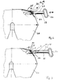
- FIG. 2 the arrangement of such a device 1 on a fifth wheel 20 is shown.
- the side wall 25 of a coupling plate has a passage opening 26 to guide the handle lever 21 to the outside.
- This pull lever 21 is connected via a linkage with a closure device for the kingpin, which is not visible in the illustration shown here.
- the handle lever 21 has a handle 24 with which the handle lever can be moved in the direction of the arrow. Adjacent to the handle lever 21, a safety lever 22 is arranged, which also extends outwardly through the opening 26 and is connected by a spring 23 in the region of the handle 24.
- the device 1 is arranged, wherein the sensor of the device 1 at the bottom of the housing 10th is provided and therefore not visible. Since the handle lever 21 is located under the device 1, this preferably has on its upper side a contact element 12 in the form of a metal plate 13. Instead of a metal plate and a magnet can be used. In the FIG. 2 This metal plate is located under the sensor. This is the position in which the closure device is in the closed position and the handle lever 21 is in its securing position.
- the display device has an optical display element 7 which lights up when the closure position is present ( FIG. 2 ) and goes off when the handle is moved to the open position ( FIG. 3 ).
- the optical display element 7 is mounted laterally on the housing 10 and thus visible from the operating side.
- the device 1 is disposed on the peripheral wall 25 on the fifth wheel plate 20.
- the locking lever 30 is a separate lever that is not connected to the handle lever 21.
- the contact element 12 is likewise arranged in the form of a metal plate 13. Before the handle lever 21 can be moved, previously the locking lever 30 must be moved, as shown in the FIG. 5 is shown. Only then is it possible, the handle lever 21 to open the Locking device on the safety hook 31 on the safety lever 30 to move.
- FIGS. 6 and 7 another embodiment is shown.
- a pivot bearing 27 is provided, in which a pivot lever 14 is mounted with a contact element 12 mounted thereon and thus secures the access lever 21.
- the device 1 according to the invention is arranged, which has the sensor on the underside. In the in FIG. 6 shown position is the handle lever 21 and thus the closure device in the closed position. Accordingly, the optical display 7 lights up.
- the pivot lever 14 Before the access lever 21 can be moved to open the shutter, the pivot lever 14 must be pivoted in the pivot bearing 27 by 90 °, so that the respective leg of the pivot lever is removed from the sensor of the sensor device of the device 1. The device 1 detects thereby the open position and the display element 7 goes out.
- a distance sensor 3b is seen, which is arranged at the top of the housing and the distance to a semi-trailer (not shown) detected.
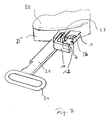
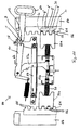
- a bolt coupling 40 is shown having a coupling housing 41 into which the front end of, for example, a drawbar can be inserted.
- the coupling pin 44 In the housing there is an opening for the coupling pin 44, which can be moved in the vertical direction.
- the lever 43 is provided.
- the device 1 according to the invention with the display element 7 is arranged on the left side of the clutch housing 41.
- the functioning is in the FIGS. 9a and 9b shown.
- the device 1 has a mechanical switching element in the form of a securing bolt 18 with the contact element 12 at its free end, which is spring-mounted on the housing 1 and extends through the housing 10 to the outside.
- FIG. 9a shows the open position of the coupling pin 44th
- FIG. 9b shows the closed position in which the coupling pin 44 is displaced relative to the securing pin 18, so that the locking pin 18, driven by the compression spring 19, dips into a recess in the coupling pin 44.
- the respective position can also be detected on the basis of the position of the securing bolt 18, such as a comparison of FIGS. 9a and 9b shows. It is thereby possible to detect the locking position of the coupling bolt 44.
- a displacement device 50 is shown on a towing vehicle (not shown) on a towing vehicle (not shown) on a towing vehicle (not shown) are arranged parallel to each other guide rails 54 with toothed racks 51 and teeth 55.
- the teeth 55 are arranged facing inwards and lie in a common plane.
- a carriage 70 is slidably disposed, the frame in the Figures 10 and 11 not shown.
- a locking device with blocking pieces 52a, b is arranged, which are connected via levers 53a, b with a handle lever 61.
- these Blocking pieces 52a, b from an unlocked position (FIG. FIG. 10 ) into a locked position ( FIG. 11 ) and vice versa.
- the device 1 according to the invention On a wall element 58, through which the pull handle lever 61 is guided, the device 1 according to the invention is arranged.
- a contact element 12 is arranged on the upper side of the handle lever 61.
- the handle lever 61 is fixed with its locking recess 62 on the wall member 58.
- the contact plate 12 is disposed outside the device 1, so that the device 1 detects the unlocked position.
- the contact element 12 is moved under the device 1 so that it can detect the locking position with the sensor unit. Via the visual display 7, a corresponding signal is displayed.
- a device 1 ' accordinging to the invention arranged, the inside has three position sensors 3c and outboard three optical displays 7' has.
- the position sensors 3c Upon engagement of the teeth 56 of the blocking piece 52a in the gaps between the teeth 55 of the rack 51, they are detected by the position sensors 3c.
- the position of the blocking pieces 52a, b also changes, so that not all the teeth 56 of the blocking piece 52a are opposed to a position sensor 3c.
- the optical display elements 7 ' likewise light up correspondingly. On the basis of the number of illuminated display elements, the driver can recognize when passing in which position the slide of the displacement device is located.
Landscapes
- Engineering & Computer Science (AREA)
- Transportation (AREA)
- Mechanical Engineering (AREA)
- Chemical & Material Sciences (AREA)
- Combustion & Propulsion (AREA)
- Lighting Device Outwards From Vehicle And Optical Signal (AREA)
- Length Measuring Devices With Unspecified Measuring Means (AREA)
- Mechanical Control Devices (AREA)
- Measuring Fluid Pressure (AREA)
- Handcart (AREA)
- Measurement Of Distances Traversed On The Ground (AREA)
- Measurement Of Mechanical Vibrations Or Ultrasonic Waves (AREA)
- Devices For Indicating Variable Information By Combining Individual Elements (AREA)
- Arrangement And Mounting Of Devices That Control Transmission Of Motive Force (AREA)
- Measurement Of Length, Angles, Or The Like Using Electric Or Magnetic Means (AREA)
Priority Applications (1)
| Application Number | Priority Date | Filing Date | Title |
|---|---|---|---|
| PL09162089T PL2090500T3 (pl) | 2005-03-24 | 2006-03-21 | Urządzenie do wykrywania i wskazywania pozycji elementów składowych sprzęgów pojazdów |
Applications Claiming Priority (2)
| Application Number | Priority Date | Filing Date | Title |
|---|---|---|---|
| DE102005014977A DE102005014977B4 (de) | 2005-03-24 | 2005-03-24 | Vorrichtung zum Nachweis und zur Anzeige der Position von Komponenten von Fahrzeugkupplungen |
| EP06723569A EP1861306B1 (fr) | 2005-03-24 | 2006-03-21 | Dispositif de detection et d'indication de la position d'elements d'attelage d'un vehicule |
Related Parent Applications (2)
| Application Number | Title | Priority Date | Filing Date |
|---|---|---|---|
| EP06723569.7 Division | 2006-03-21 | ||
| EP06723569A Division EP1861306B1 (fr) | 2005-03-24 | 2006-03-21 | Dispositif de detection et d'indication de la position d'elements d'attelage d'un vehicule |
Publications (2)
| Publication Number | Publication Date |
|---|---|
| EP2090500A1 true EP2090500A1 (fr) | 2009-08-19 |
| EP2090500B1 EP2090500B1 (fr) | 2010-09-29 |
Family
ID=36599090
Family Applications (3)
| Application Number | Title | Priority Date | Filing Date |
|---|---|---|---|
| EP09162092A Active EP2093134B1 (fr) | 2005-03-24 | 2006-03-21 | Dispositif de contrôle et d'affichage de la position de composants d'embrayages de véhicules |
| EP06723569A Not-in-force EP1861306B1 (fr) | 2005-03-24 | 2006-03-21 | Dispositif de detection et d'indication de la position d'elements d'attelage d'un vehicule |
| EP09162089A Active EP2090500B1 (fr) | 2005-03-24 | 2006-03-21 | Dispositif de détection et d'indication de la position d'éléments d'attelage d'un véhicule |
Family Applications Before (2)
| Application Number | Title | Priority Date | Filing Date |
|---|---|---|---|
| EP09162092A Active EP2093134B1 (fr) | 2005-03-24 | 2006-03-21 | Dispositif de contrôle et d'affichage de la position de composants d'embrayages de véhicules |
| EP06723569A Not-in-force EP1861306B1 (fr) | 2005-03-24 | 2006-03-21 | Dispositif de detection et d'indication de la position d'elements d'attelage d'un vehicule |
Country Status (12)
| Country | Link |
|---|---|
| US (1) | US7932816B2 (fr) |
| EP (3) | EP2093134B1 (fr) |
| CN (1) | CN101180204B (fr) |
| AR (1) | AR055754A1 (fr) |
| AT (3) | ATE444889T1 (fr) |
| BR (1) | BRPI0609431A2 (fr) |
| CA (1) | CA2602033C (fr) |
| DE (3) | DE102005014977B4 (fr) |
| EA (1) | EA011966B1 (fr) |
| ES (3) | ES2333160T3 (fr) |
| PL (3) | PL2090500T3 (fr) |
| WO (1) | WO2006100025A1 (fr) |
Families Citing this family (16)
| Publication number | Priority date | Publication date | Assignee | Title |
|---|---|---|---|---|
| US8421640B1 (en) * | 2010-06-07 | 2013-04-16 | Edward Wayne Larson | Tractor lift detection system for gantry cranes |
| DE102011085338A1 (de) * | 2011-10-27 | 2013-05-02 | Rockinger Agriculture Gmbh | Fernanzeige für Anhängekupplung |
| US9723692B2 (en) * | 2015-05-20 | 2017-08-01 | Saf-Holland, Inc | Fifth wheel coupling detection system with inspection and indication lighting arrangement |
| US9862242B2 (en) | 2015-12-21 | 2018-01-09 | Jason P. Lurie | Coupling system |
| EP3379222B1 (fr) | 2017-03-22 | 2020-12-30 | Methode Electronics Malta Ltd. | Ensemble de capteur à base magnétoélastique |
| US10406874B2 (en) | 2017-09-27 | 2019-09-10 | Roger D. McKelvey | Fifth wheel trailer lock |
| US11221262B2 (en) | 2018-02-27 | 2022-01-11 | Methode Electronics, Inc. | Towing systems and methods using magnetic field sensing |
| US11491832B2 (en) | 2018-02-27 | 2022-11-08 | Methode Electronics, Inc. | Towing systems and methods using magnetic field sensing |
| US11014417B2 (en) | 2018-02-27 | 2021-05-25 | Methode Electronics, Inc. | Towing systems and methods using magnetic field sensing |
| US11135882B2 (en) | 2018-02-27 | 2021-10-05 | Methode Electronics, Inc. | Towing systems and methods using magnetic field sensing |
| US11084342B2 (en) | 2018-02-27 | 2021-08-10 | Methode Electronics, Inc. | Towing systems and methods using magnetic field sensing |
| US10670479B2 (en) | 2018-02-27 | 2020-06-02 | Methode Electronics, Inc. | Towing systems and methods using magnetic field sensing |
| US11731471B2 (en) | 2018-04-27 | 2023-08-22 | Fontaine Fifth Wheel Company | Methods and systems for monitoring coupling of fifth wheels to kingpins |
| US11524536B2 (en) | 2019-02-14 | 2022-12-13 | Fontaine Fifth Wheel Company | Apparatuses, systems, and methods for determining and verifying operational states of fifth wheels |
| US20210125433A1 (en) * | 2019-10-23 | 2021-04-29 | Brandon Gonzalez | Safety system for coupling truck and trailer |
| EP4257462A1 (fr) | 2022-04-07 | 2023-10-11 | Sampa Otomotiv Sanayi Ve Ticaret Anonim Sirketi | Selette d'attelage avec élélment de réglage à déplacement automatique et son procédé |
Citations (5)
| Publication number | Priority date | Publication date | Assignee | Title |
|---|---|---|---|---|
| EP0509137A1 (fr) * | 1991-04-16 | 1992-10-21 | ROCKINGER Spezialfabrik für Anhängerkupplungen GmbH & Co. | Dispositif de sellette d'attelage mot clef: poignée de manoeuvre |
| US5861802A (en) * | 1996-03-04 | 1999-01-19 | Holland Hitch Company | Fifth wheel hitch coupling control system |
| US6100794A (en) * | 1999-02-18 | 2000-08-08 | Hillier; Terrence E. | Fifth wheel coupling safety system |
| US6222457B1 (en) * | 1999-10-12 | 2001-04-24 | Stephen Scott Keneally | Electronic trailer hitching system |
| EP1396417A1 (fr) * | 2002-09-06 | 2004-03-10 | Jost-Werke GmbH & Co. KG | Dispositif pour indiquer la position de fermeture d'une sellette d'attelage et disposition de senseurs |
Family Cites Families (17)
| Publication number | Priority date | Publication date | Assignee | Title |
|---|---|---|---|---|
| US3868127A (en) | 1974-07-26 | 1975-02-25 | Pullman Inc | Engaged kingpin detector assembly for fifth wheel plate |
| DE3226360C2 (de) * | 1982-07-14 | 1986-04-24 | Rockinger Spezialfabrik für Anhängerkupplungen GmbH & Co, 8000 München | Anhängerkupplung |
| DE3909087A1 (de) * | 1989-03-20 | 1990-09-27 | Rockinger Spezial Fab Joh | Fernanzeigevorrichtung fuer fahrzeug-anhaengerkupplungen |
| AT392940B (de) * | 1989-12-14 | 1991-07-10 | Scharmueller Josef Ing | Anhaengekupplung, insbesondere fuer traktoren |
| US5477207A (en) * | 1993-10-04 | 1995-12-19 | C & M Safety Systems, Inc. | Warning device for a vehicle and trailer coupling system |
| US5617072A (en) * | 1994-12-07 | 1997-04-01 | Rockin' Chair Truckers Co. | Position signaling apparatus |
| IT1286196B1 (it) * | 1996-08-08 | 1998-07-08 | C B M Spa | Sistema di controllo e sicurezza a gestione elettronica per collegamento fra una motrice ed un veicolo trainato |
| US5988666A (en) * | 1997-07-18 | 1999-11-23 | Holland Hitch Company | Fifth wheel hitch release |
| US6592230B2 (en) * | 1997-10-16 | 2003-07-15 | Holland Hitch Company | Truck rearview mirror assembly having a display for displaying trailer coupling status information |
| US6285278B1 (en) * | 2000-01-28 | 2001-09-04 | Holland Hitch Company | Electronic system for monitoring a fifth wheel hitch |
| DE29722370U1 (de) * | 1997-12-18 | 1998-04-02 | Brecht Thomas | Sicherheitsbolzen - Einrastanzeige für Lastkraftwagen - Anhänger - Kupplungen |
| DE19820139B4 (de) * | 1998-05-06 | 2008-05-29 | Georg Fischer Verkehrstechnik Gmbh | Vorrichtung zur Überwachung des ordnungsgemässen Verriegelns und Sicherns einer Sattelkupplung eines Sattelfahrzeugs |
| US6011492A (en) * | 1998-06-30 | 2000-01-04 | Garesche; Carl E. | Vehicle warning system for visual communication of hazardous traffic conditions |
| US6452485B1 (en) * | 2000-01-28 | 2002-09-17 | The Holland Group, Inc. | Electronic system for monitoring a fifth wheel hitch |
| US6736420B2 (en) * | 2000-03-03 | 2004-05-18 | Jost International Corporation | Carrier assembly for a fifth wheel |
| JP2002331971A (ja) * | 2001-05-07 | 2002-11-19 | Hino Motors Ltd | スライド型連結牽引装置 |
| DE102005031365B4 (de) | 2005-06-30 | 2008-04-30 | Jost-Werke Gmbh | Vorrichtung zum Nachweis und zur Anzeige der Position von Komponenten von Fahrzeugkupplungen |
-
2005
- 2005-03-24 DE DE102005014977A patent/DE102005014977B4/de not_active Expired - Fee Related
-
2006
- 2006-03-21 AT AT06723569T patent/ATE444889T1/de active
- 2006-03-21 CA CA2602033A patent/CA2602033C/fr not_active Expired - Fee Related
- 2006-03-21 WO PCT/EP2006/002555 patent/WO2006100025A1/fr active Application Filing
- 2006-03-21 ES ES06723569T patent/ES2333160T3/es active Active
- 2006-03-21 AT AT09162089T patent/ATE482871T1/de active
- 2006-03-21 EP EP09162092A patent/EP2093134B1/fr active Active
- 2006-03-21 PL PL09162089T patent/PL2090500T3/pl unknown
- 2006-03-21 EP EP06723569A patent/EP1861306B1/fr not_active Not-in-force
- 2006-03-21 CN CN2006800095467A patent/CN101180204B/zh active Active
- 2006-03-21 ES ES09162092T patent/ES2362400T3/es active Active
- 2006-03-21 EP EP09162089A patent/EP2090500B1/fr active Active
- 2006-03-21 ES ES09162089T patent/ES2353366T3/es active Active
- 2006-03-21 AT AT09162092T patent/ATE508931T1/de active
- 2006-03-21 EA EA200702061A patent/EA011966B1/ru not_active IP Right Cessation
- 2006-03-21 DE DE502006007996T patent/DE502006007996D1/de active Active
- 2006-03-21 PL PL06723569T patent/PL1861306T3/pl unknown
- 2006-03-21 DE DE502006005031T patent/DE502006005031D1/de active Active
- 2006-03-21 US US11/887,032 patent/US7932816B2/en not_active Expired - Fee Related
- 2006-03-21 PL PL09162092T patent/PL2093134T3/pl unknown
- 2006-03-21 BR BRPI0609431-7A patent/BRPI0609431A2/pt not_active Application Discontinuation
- 2006-03-27 AR ARP060101165A patent/AR055754A1/es active IP Right Grant
Patent Citations (6)
| Publication number | Priority date | Publication date | Assignee | Title |
|---|---|---|---|---|
| EP0509137A1 (fr) * | 1991-04-16 | 1992-10-21 | ROCKINGER Spezialfabrik für Anhängerkupplungen GmbH & Co. | Dispositif de sellette d'attelage mot clef: poignée de manoeuvre |
| US5861802A (en) * | 1996-03-04 | 1999-01-19 | Holland Hitch Company | Fifth wheel hitch coupling control system |
| US6100794A (en) * | 1999-02-18 | 2000-08-08 | Hillier; Terrence E. | Fifth wheel coupling safety system |
| US6222457B1 (en) * | 1999-10-12 | 2001-04-24 | Stephen Scott Keneally | Electronic trailer hitching system |
| EP1396417A1 (fr) * | 2002-09-06 | 2004-03-10 | Jost-Werke GmbH & Co. KG | Dispositif pour indiquer la position de fermeture d'une sellette d'attelage et disposition de senseurs |
| DE10241904A1 (de) * | 2002-09-06 | 2004-03-11 | Jost-Werke Gmbh & Co Kg | Sensor für Königszapfen |
Also Published As
| Publication number | Publication date |
|---|---|
| CA2602033C (fr) | 2012-12-18 |
| ATE508931T1 (de) | 2011-05-15 |
| ATE444889T1 (de) | 2009-10-15 |
| EP1861306B1 (fr) | 2009-10-07 |
| CN101180204B (zh) | 2010-08-04 |
| ES2362400T3 (es) | 2011-07-04 |
| EP2093134A1 (fr) | 2009-08-26 |
| EA011966B1 (ru) | 2009-06-30 |
| PL2093134T3 (pl) | 2011-10-31 |
| BRPI0609431A2 (pt) | 2010-04-06 |
| EP2093134B1 (fr) | 2011-05-11 |
| ATE482871T1 (de) | 2010-10-15 |
| EA200702061A1 (ru) | 2008-06-30 |
| PL2090500T3 (pl) | 2011-03-31 |
| CA2602033A1 (fr) | 2006-09-28 |
| PL1861306T3 (pl) | 2010-03-31 |
| DE102005014977B4 (de) | 2008-08-21 |
| ES2333160T3 (es) | 2010-02-17 |
| ES2353366T3 (es) | 2011-03-01 |
| US20080150745A1 (en) | 2008-06-26 |
| DE102005014977A1 (de) | 2006-10-05 |
| WO2006100025A1 (fr) | 2006-09-28 |
| AR055754A1 (es) | 2007-09-05 |
| DE502006007996D1 (de) | 2010-11-11 |
| US7932816B2 (en) | 2011-04-26 |
| CN101180204A (zh) | 2008-05-14 |
| EP1861306A1 (fr) | 2007-12-05 |
| EP2090500B1 (fr) | 2010-09-29 |
| DE502006005031D1 (de) | 2009-11-19 |
Similar Documents
| Publication | Publication Date | Title |
|---|---|---|
| EP2090500B1 (fr) | Dispositif de détection et d'indication de la position d'éléments d'attelage d'un véhicule | |
| EP1896317B1 (fr) | Dispositif pour identifier et afficher la position de composants d'attelages de vehicules | |
| DE102004045663B4 (de) | Verschiebevorrichtung für eine Sattelkupplung | |
| EP2508393B1 (fr) | Dispositif doté d'une unité de caméra | |
| EP1638206B1 (fr) | Dispositif de surveillance de position | |
| DE102008028434B4 (de) | Ladebordwand mit Fernbedienung | |
| EP2152553B1 (fr) | Dispositif de commande pour un véhicule équipé d'une boîte de vitesses automatique et d'un système de frein de stationnement actionné électriquement | |
| DE112017006055T5 (de) | Vorrichtung zum Öffnen und Schließen einer Fahrzeugtür | |
| DE102010039333A1 (de) | Gurtschloss mit Zustandsgeber | |
| EP3060424B1 (fr) | Indicateur de verrouillage pour siège de véhicule, siège de véhicule, véhicule automobile et procédé de verrouillage d'un siège d'automobile | |
| DE202005005191U1 (de) | Vorrichtung zum Nachweis und zur Anzeige der Position von Komponenten von Fahrzeugkupplungen | |
| DE202017100896U1 (de) | Kraftfahrzeug-Türverriegelungsstatussystem | |
| DE102019113503A1 (de) | Kupplungssystem für eine mobile Arbeitsmaschine sowie Nachrüstsystem für eine Anhängerkupplung einer mobilen Arbeitsmaschine und mobile Arbeitsmaschine mit dem Kupplungssystem | |
| DE102009037634A1 (de) | Aufzug und Verfahren zur Absicherung eines Aufzugs | |
| DE202006006864U1 (de) | Vorrichtung zur Verriegelung einer Schiebetür | |
| DE102009036769A1 (de) | Prüfeinrichtung für ein Schaltgetriebe | |
| DE10141139C1 (de) | Sicherheitseinrichtung für eine selbstfahrende Landmaschine | |
| DE102018004342A1 (de) | System zur Zustandsdarstellung wenigstens einer Cargotür eines Flugzeugs | |
| DE10306361B4 (de) | Türgriffanordnung für eine Kraftfahrzeugtür | |
| DE102018206235A1 (de) | Montagevorrichtung zur Anbringung von Sensoren an einem Schienenfahrzeug | |
| DE3702479A1 (de) | Diebstahlsicherung des schalthebels in einem handschaltgetriebe | |
| DE102015009172A1 (de) | Verriegelungsvorrichtung für ein kippbares Fahrerhaus eines Nutzfahrzeugs | |
| EP3621046A1 (fr) | Dispositif d'alarme pour poids lourds | |
| DE102019135862A1 (de) | Sensorsystem mit Notfall-Eigenschaft für ein Fahrzeug | |
| DE102017112371A1 (de) | Sensoranlage zur Überwachung von automatischen Türen und automatische Tür |
Legal Events
| Date | Code | Title | Description |
|---|---|---|---|
| PUAI | Public reference made under article 153(3) epc to a published international application that has entered the european phase |
Free format text: ORIGINAL CODE: 0009012 |
|
| 17P | Request for examination filed |
Effective date: 20090605 |
|
| AC | Divisional application: reference to earlier application |
Ref document number: 1861306 Country of ref document: EP Kind code of ref document: P |
|
| AK | Designated contracting states |
Kind code of ref document: A1 Designated state(s): AT BE BG CH CY CZ DE DK EE ES FI FR GB GR HU IE IS IT LI LT LU LV MC NL PL PT RO SE SI SK TR |
|
| GRAP | Despatch of communication of intention to grant a patent |
Free format text: ORIGINAL CODE: EPIDOSNIGR1 |
|
| RIC1 | Information provided on ipc code assigned before grant |
Ipc: B62D 53/08 20060101AFI20100329BHEP |
|
| GRAS | Grant fee paid |
Free format text: ORIGINAL CODE: EPIDOSNIGR3 |
|
| GRAA | (expected) grant |
Free format text: ORIGINAL CODE: 0009210 |
|
| AC | Divisional application: reference to earlier application |
Ref document number: 1861306 Country of ref document: EP Kind code of ref document: P |
|
| AK | Designated contracting states |
Kind code of ref document: B1 Designated state(s): AT BE BG CH CY CZ DE DK EE ES FI FR GB GR HU IE IS IT LI LT LU LV MC NL PL PT RO SE SI SK TR |
|
| REG | Reference to a national code |
Ref country code: GB Ref legal event code: FG4D Free format text: NOT ENGLISH |
|
| REG | Reference to a national code |
Ref country code: CH Ref legal event code: EP |
|
| REG | Reference to a national code |
Ref country code: IE Ref legal event code: FG4D Free format text: LANGUAGE OF EP DOCUMENT: GERMAN |
|
| REF | Corresponds to: |
Ref document number: 502006007996 Country of ref document: DE Date of ref document: 20101111 Kind code of ref document: P |
|
| REG | Reference to a national code |
Ref country code: NL Ref legal event code: T3 |
|
| REG | Reference to a national code |
Ref country code: CH Ref legal event code: NV Representative=s name: R. A. EGLI & CO. PATENTANWAELTE |
|
| REG | Reference to a national code |
Ref country code: SE Ref legal event code: TRGR |
|
| PG25 | Lapsed in a contracting state [announced via postgrant information from national office to epo] |
Ref country code: LT Free format text: LAPSE BECAUSE OF FAILURE TO SUBMIT A TRANSLATION OF THE DESCRIPTION OR TO PAY THE FEE WITHIN THE PRESCRIBED TIME-LIMIT Effective date: 20100929 Ref country code: FI Free format text: LAPSE BECAUSE OF FAILURE TO SUBMIT A TRANSLATION OF THE DESCRIPTION OR TO PAY THE FEE WITHIN THE PRESCRIBED TIME-LIMIT Effective date: 20100929 |
|
| LTIE | Lt: invalidation of european patent or patent extension |
Effective date: 20100929 |
|
| PG25 | Lapsed in a contracting state [announced via postgrant information from national office to epo] |
Ref country code: SI Free format text: LAPSE BECAUSE OF FAILURE TO SUBMIT A TRANSLATION OF THE DESCRIPTION OR TO PAY THE FEE WITHIN THE PRESCRIBED TIME-LIMIT Effective date: 20100929 |
|
| REG | Reference to a national code |
Ref country code: ES Ref legal event code: FG2A Effective date: 20110217 |
|
| PG25 | Lapsed in a contracting state [announced via postgrant information from national office to epo] |
Ref country code: LV Free format text: LAPSE BECAUSE OF FAILURE TO SUBMIT A TRANSLATION OF THE DESCRIPTION OR TO PAY THE FEE WITHIN THE PRESCRIBED TIME-LIMIT Effective date: 20100929 Ref country code: GR Free format text: LAPSE BECAUSE OF FAILURE TO SUBMIT A TRANSLATION OF THE DESCRIPTION OR TO PAY THE FEE WITHIN THE PRESCRIBED TIME-LIMIT Effective date: 20101230 |
|
| REG | Reference to a national code |
Ref country code: PL Ref legal event code: T3 |
|
| REG | Reference to a national code |
Ref country code: IE Ref legal event code: FD4D |
|
| PG25 | Lapsed in a contracting state [announced via postgrant information from national office to epo] |
Ref country code: CZ Free format text: LAPSE BECAUSE OF FAILURE TO SUBMIT A TRANSLATION OF THE DESCRIPTION OR TO PAY THE FEE WITHIN THE PRESCRIBED TIME-LIMIT Effective date: 20100929 Ref country code: SK Free format text: LAPSE BECAUSE OF FAILURE TO SUBMIT A TRANSLATION OF THE DESCRIPTION OR TO PAY THE FEE WITHIN THE PRESCRIBED TIME-LIMIT Effective date: 20100929 Ref country code: EE Free format text: LAPSE BECAUSE OF FAILURE TO SUBMIT A TRANSLATION OF THE DESCRIPTION OR TO PAY THE FEE WITHIN THE PRESCRIBED TIME-LIMIT Effective date: 20100929 Ref country code: RO Free format text: LAPSE BECAUSE OF FAILURE TO SUBMIT A TRANSLATION OF THE DESCRIPTION OR TO PAY THE FEE WITHIN THE PRESCRIBED TIME-LIMIT Effective date: 20100929 Ref country code: IS Free format text: LAPSE BECAUSE OF FAILURE TO SUBMIT A TRANSLATION OF THE DESCRIPTION OR TO PAY THE FEE WITHIN THE PRESCRIBED TIME-LIMIT Effective date: 20110129 Ref country code: PT Free format text: LAPSE BECAUSE OF FAILURE TO SUBMIT A TRANSLATION OF THE DESCRIPTION OR TO PAY THE FEE WITHIN THE PRESCRIBED TIME-LIMIT Effective date: 20110131 |
|
| PG25 | Lapsed in a contracting state [announced via postgrant information from national office to epo] |
Ref country code: IE Free format text: LAPSE BECAUSE OF FAILURE TO SUBMIT A TRANSLATION OF THE DESCRIPTION OR TO PAY THE FEE WITHIN THE PRESCRIBED TIME-LIMIT Effective date: 20100929 |
|
| PLBE | No opposition filed within time limit |
Free format text: ORIGINAL CODE: 0009261 |
|
| STAA | Information on the status of an ep patent application or granted ep patent |
Free format text: STATUS: NO OPPOSITION FILED WITHIN TIME LIMIT |
|
| PG25 | Lapsed in a contracting state [announced via postgrant information from national office to epo] |
Ref country code: DK Free format text: LAPSE BECAUSE OF FAILURE TO SUBMIT A TRANSLATION OF THE DESCRIPTION OR TO PAY THE FEE WITHIN THE PRESCRIBED TIME-LIMIT Effective date: 20100929 |
|
| REG | Reference to a national code |
Ref country code: DE Ref legal event code: R097 Ref document number: 502006007996 Country of ref document: DE Effective date: 20110630 |
|
| PG25 | Lapsed in a contracting state [announced via postgrant information from national office to epo] |
Ref country code: MC Free format text: LAPSE BECAUSE OF NON-PAYMENT OF DUE FEES Effective date: 20110331 |
|
| REG | Reference to a national code |
Ref country code: DE Ref legal event code: R082 Ref document number: 502006007996 Country of ref document: DE Representative=s name: MEHLER ACHLER PATENTANWAELTE, DE Ref country code: DE Ref legal event code: R082 Ref document number: 502006007996 Country of ref document: DE Representative=s name: MEHLER ACHLER PATENTANWAELTE PARTNERSCHAFT MBB, DE |
|
| PG25 | Lapsed in a contracting state [announced via postgrant information from national office to epo] |
Ref country code: LU Free format text: LAPSE BECAUSE OF NON-PAYMENT OF DUE FEES Effective date: 20110321 Ref country code: CY Free format text: LAPSE BECAUSE OF FAILURE TO SUBMIT A TRANSLATION OF THE DESCRIPTION OR TO PAY THE FEE WITHIN THE PRESCRIBED TIME-LIMIT Effective date: 20100929 |
|
| PG25 | Lapsed in a contracting state [announced via postgrant information from national office to epo] |
Ref country code: BG Free format text: LAPSE BECAUSE OF FAILURE TO SUBMIT A TRANSLATION OF THE DESCRIPTION OR TO PAY THE FEE WITHIN THE PRESCRIBED TIME-LIMIT Effective date: 20101229 Ref country code: TR Free format text: LAPSE BECAUSE OF FAILURE TO SUBMIT A TRANSLATION OF THE DESCRIPTION OR TO PAY THE FEE WITHIN THE PRESCRIBED TIME-LIMIT Effective date: 20100929 |
|
| PG25 | Lapsed in a contracting state [announced via postgrant information from national office to epo] |
Ref country code: HU Free format text: LAPSE BECAUSE OF FAILURE TO SUBMIT A TRANSLATION OF THE DESCRIPTION OR TO PAY THE FEE WITHIN THE PRESCRIBED TIME-LIMIT Effective date: 20100929 |
|
| REG | Reference to a national code |
Ref country code: FR Ref legal event code: PLFP Year of fee payment: 11 |
|
| REG | Reference to a national code |
Ref country code: FR Ref legal event code: PLFP Year of fee payment: 12 |
|
| REG | Reference to a national code |
Ref country code: DE Ref legal event code: R082 Ref document number: 502006007996 Country of ref document: DE Representative=s name: MEHLER ACHLER PATENTANWAELTE PARTNERSCHAFT MBB, DE Ref country code: DE Ref legal event code: R081 Ref document number: 502006007996 Country of ref document: DE Owner name: JOST-WERKE DEUTSCHLAND GMBH, DE Free format text: FORMER OWNER: JOST-WERKE GMBH, 63263 NEU-ISENBURG, DE |
|
| REG | Reference to a national code |
Ref country code: AT Ref legal event code: HC Ref document number: 482871 Country of ref document: AT Kind code of ref document: T Owner name: JOST-WERKE DEUTSCHLAND GMBH, DE Effective date: 20171002 |
|
| REG | Reference to a national code |
Ref country code: FR Ref legal event code: CD Owner name: JOST-WERKE DEUTSCHLAND GMBH, DE Effective date: 20171229 |
|
| REG | Reference to a national code |
Ref country code: FR Ref legal event code: PLFP Year of fee payment: 13 |
|
| PGFP | Annual fee paid to national office [announced via postgrant information from national office to epo] |
Ref country code: PL Payment date: 20190109 Year of fee payment: 11 Ref country code: CH Payment date: 20190322 Year of fee payment: 14 |
|
| PGFP | Annual fee paid to national office [announced via postgrant information from national office to epo] |
Ref country code: AT Payment date: 20190328 Year of fee payment: 14 |
|
| PGFP | Annual fee paid to national office [announced via postgrant information from national office to epo] |
Ref country code: IT Payment date: 20190329 Year of fee payment: 14 |
|
| PGFP | Annual fee paid to national office [announced via postgrant information from national office to epo] |
Ref country code: NL Payment date: 20200325 Year of fee payment: 15 Ref country code: SE Payment date: 20200320 Year of fee payment: 15 |
|
| PGFP | Annual fee paid to national office [announced via postgrant information from national office to epo] |
Ref country code: FR Payment date: 20200401 Year of fee payment: 15 |
|
| REG | Reference to a national code |
Ref country code: CH Ref legal event code: PL |
|
| REG | Reference to a national code |
Ref country code: AT Ref legal event code: MM01 Ref document number: 482871 Country of ref document: AT Kind code of ref document: T Effective date: 20200321 |
|
| REG | Reference to a national code |
Ref country code: BE Ref legal event code: MM Effective date: 20200331 |
|
| PG25 | Lapsed in a contracting state [announced via postgrant information from national office to epo] |
Ref country code: CH Free format text: LAPSE BECAUSE OF NON-PAYMENT OF DUE FEES Effective date: 20200331 Ref country code: AT Free format text: LAPSE BECAUSE OF NON-PAYMENT OF DUE FEES Effective date: 20200321 Ref country code: LI Free format text: LAPSE BECAUSE OF NON-PAYMENT OF DUE FEES Effective date: 20200331 |
|
| PG25 | Lapsed in a contracting state [announced via postgrant information from national office to epo] |
Ref country code: BE Free format text: LAPSE BECAUSE OF NON-PAYMENT OF DUE FEES Effective date: 20200331 |
|
| REG | Reference to a national code |
Ref country code: ES Ref legal event code: FD2A Effective date: 20210802 |
|
| REG | Reference to a national code |
Ref country code: DE Ref legal event code: R082 Ref document number: 502006007996 Country of ref document: DE Representative=s name: WSL PATENTANWAELTE PARTNERSCHAFT MBB, DE |
|
| PG25 | Lapsed in a contracting state [announced via postgrant information from national office to epo] |
Ref country code: IT Free format text: LAPSE BECAUSE OF NON-PAYMENT OF DUE FEES Effective date: 20200321 |
|
| REG | Reference to a national code |
Ref country code: NL Ref legal event code: MM Effective date: 20210401 |
|
| PG25 | Lapsed in a contracting state [announced via postgrant information from national office to epo] |
Ref country code: ES Free format text: LAPSE BECAUSE OF NON-PAYMENT OF DUE FEES Effective date: 20200322 |
|
| PG25 | Lapsed in a contracting state [announced via postgrant information from national office to epo] |
Ref country code: FR Free format text: LAPSE BECAUSE OF NON-PAYMENT OF DUE FEES Effective date: 20210331 Ref country code: SE Free format text: LAPSE BECAUSE OF NON-PAYMENT OF DUE FEES Effective date: 20210322 Ref country code: NL Free format text: LAPSE BECAUSE OF NON-PAYMENT OF DUE FEES Effective date: 20210401 |
|
| PG25 | Lapsed in a contracting state [announced via postgrant information from national office to epo] |
Ref country code: PL Free format text: LAPSE BECAUSE OF NON-PAYMENT OF DUE FEES Effective date: 20200321 |
|
| PGFP | Annual fee paid to national office [announced via postgrant information from national office to epo] |
Ref country code: DE Payment date: 20230323 Year of fee payment: 18 |
|
| PGFP | Annual fee paid to national office [announced via postgrant information from national office to epo] |
Ref country code: GB Payment date: 20240320 Year of fee payment: 19 |