EP2090500A1 - Device for detecting and displaying the position of components of vehicle couplings - Google Patents
Device for detecting and displaying the position of components of vehicle couplings Download PDFInfo
- Publication number
- EP2090500A1 EP2090500A1 EP09162089A EP09162089A EP2090500A1 EP 2090500 A1 EP2090500 A1 EP 2090500A1 EP 09162089 A EP09162089 A EP 09162089A EP 09162089 A EP09162089 A EP 09162089A EP 2090500 A1 EP2090500 A1 EP 2090500A1
- Authority
- EP
- European Patent Office
- Prior art keywords
- sensor
- arrangement according
- display
- lever
- wheel
- Prior art date
- Legal status (The legal status is an assumption and is not a legal conclusion. Google has not performed a legal analysis and makes no representation as to the accuracy of the status listed.)
- Granted
Links
Images


Classifications
-
- B—PERFORMING OPERATIONS; TRANSPORTING
- B62—LAND VEHICLES FOR TRAVELLING OTHERWISE THAN ON RAILS
- B62D—MOTOR VEHICLES; TRAILERS
- B62D53/00—Tractor-trailer combinations; Road trains
- B62D53/04—Tractor-trailer combinations; Road trains comprising a vehicle carrying an essential part of the other vehicle's load by having supporting means for the front or rear part of the other vehicle
- B62D53/08—Fifth wheel traction couplings
-
- B—PERFORMING OPERATIONS; TRANSPORTING
- B60—VEHICLES IN GENERAL
- B60D—VEHICLE CONNECTIONS
- B60D1/00—Traction couplings; Hitches; Draw-gear; Towing devices
- B60D1/24—Traction couplings; Hitches; Draw-gear; Towing devices characterised by arrangements for particular functions
- B60D1/28—Traction couplings; Hitches; Draw-gear; Towing devices characterised by arrangements for particular functions for preventing unwanted disengagement, e.g. safety appliances
-
- B—PERFORMING OPERATIONS; TRANSPORTING
- B60—VEHICLES IN GENERAL
- B60D—VEHICLE CONNECTIONS
- B60D1/00—Traction couplings; Hitches; Draw-gear; Towing devices
- B60D1/58—Auxiliary devices
-
- B—PERFORMING OPERATIONS; TRANSPORTING
- B62—LAND VEHICLES FOR TRAVELLING OTHERWISE THAN ON RAILS
- B62D—MOTOR VEHICLES; TRAILERS
- B62D53/00—Tractor-trailer combinations; Road trains
- B62D53/04—Tractor-trailer combinations; Road trains comprising a vehicle carrying an essential part of the other vehicle's load by having supporting means for the front or rear part of the other vehicle
- B62D53/08—Fifth wheel traction couplings
- B62D53/0807—Fifth wheel traction couplings adjustable coupling saddles mounted on sub-frames; Mounting plates therefor
- B62D53/0814—Fifth wheel traction couplings adjustable coupling saddles mounted on sub-frames; Mounting plates therefor with adjustment of the clearance between the tractor or the trailer
-
- B—PERFORMING OPERATIONS; TRANSPORTING
- B62—LAND VEHICLES FOR TRAVELLING OTHERWISE THAN ON RAILS
- B62D—MOTOR VEHICLES; TRAILERS
- B62D53/00—Tractor-trailer combinations; Road trains
- B62D53/04—Tractor-trailer combinations; Road trains comprising a vehicle carrying an essential part of the other vehicle's load by having supporting means for the front or rear part of the other vehicle
- B62D53/08—Fifth wheel traction couplings
- B62D53/10—Fifth wheel traction couplings with means for preventing accidental uncoupling
Definitions
- the invention relates to a device for detecting and displaying the position of components of vehicle clutches, in particular of fifth wheel couplings.
- the invention also relates to an arrangement of such a device on the outside of fifth wheel couplings or of shifting devices of a fifth wheel.
- a device for indicating the closure state of a fifth wheel wherein a first sensor is disposed in the region of the receiving opening of the fifth wheel and detects the kingpin and a second sensor comprises a magnetosensitive sensor which cooperates with a lever mounted on a lever, both sensors different mechanisms of action are based. These sensors are connected to a display unit in the cab of the tractor.
- the signal transmission as well as the energy supply of the sensors is usually carried out via cable sets and the signal evaluation via corresponding control electronics.
- the installation cost of such systems is large and is often in a poor ratio to the effect achieved, which hampers greater dissemination of this desirable and security-serving equipment hindering.
- a fifth wheel displacement device which comprises two guide rails with toothed racks on which a carriage is slidably mounted, which carries the fifth wheel.
- a locking device On the carriage a locking device is arranged with blocking pieces, which engage in the toothed racks.
- One of the blocking pieces is connected to an opening lever, which in turn with an actuating device, for. B. may be connected to a manual operation lever handle.
- an actuating device for. B.
- the driver must perform a visual inspection of the vehicle, the fifth wheel, the closure device, etc. before starting the journey.
- a device which is characterized by a combined sensor and display unit, which is arranged in a common housing, wherein the sensor unit at least one sensor and the display unit has at least one display element.
- the advantage of the device is that a compact device is provided, which can be placed at the site of the review and there emits a preferably optical or audible signal.
- a complex cabling of the sensor unit with a arranged in the cab display device is eliminated.
- There is therefore provided a low-cost device which can be easily arranged at the points where a check should be made.
- the visual inspection can be done by the driver in passing, without the need for additional aids such. B. flashlights, etc., to check, for example, the closure state of a fifth wheel or the position of a displacement device.
- the combined sensor and display unit has its own voltage source, which is preferably arranged in the housing.
- This measure also contributes to the universal applicability of the device according to the invention. Cabling to the power supply is eliminated.
- a voltage source batteries, rechargeable batteries or z.
- B. electrokinematical generators can be used.
- the combined sensor and display unit preferably has an electronic evaluation unit.
- this evaluation unit not only the sensor signal can be evaluated as to whether a shutter state exists or not (yes / no signal), but such an evaluation unit also makes it possible to evaluate the state of the power supply (eg battery or battery).
- the device may also comprise at least one distance sensor. With a device equipped with such a distance sensor, it is possible, for example, to check the correct position of a semitrailer on the fifth wheel on a fifth wheel. On the basis of the determined distance from the device to the underside of the trailer can be determined whether it is in the prescribed position in which engages the kingpin in the closure device of the fifth wheel.
- sensors inductive sensors magnetic sensors, force sensors, pressure sensors or reed sensors can be considered.
- the sensors operate without contact, with electromagnetic sensors being preferred.
- the senor may also have a switching element, in particular a mechanical switching element.
- a switching element in particular a mechanical switching element.
- the display unit preferably has an optical display element arranged on the housing.
- This can be z. B. a lamp, in particular an LED display.
- this optical display element is arranged on the housing in such a way that, in accordance with the position of the device on the vehicle, it can be easily perceived by the driver when the driver does so.
- the display unit may exclusively or additionally comprise an acoustic display element and / or a mechanical display element.
- mechanical display elements come Winker, pins or the like in question.
- acoustic display elements are Beeper or buzzer preferred.
- the display on the display element can be permanent, for example, by a steady light or continuous tone.
- the display can not be designed to be permanent and z. B. in the form of a flashing light or the like.
- closure state z. B. a fifth wheel by an optical or acoustic signal. It may also be expedient to signal the open position. Which type of display is selected depends on the type of position of the vehicle component to be detected and / or its arrangement on the vehicle.
- the inventive arrangement of the described device provides that the device is arranged on the outside of a fifth wheel or a sliding device of a fifth wheel and adjacent to a manual actuating element of a locking or locking device, wherein a contact element of the type is arranged on the manual actuating element or actuated by the manual actuating element is that it interacts in the closed and locked position with the sensor of the sensor unit.
- the outside of a fifth wheel or a displacement device means a suitable location, which is easily visible from the outside, so that the display device is easily recognizable when passing the vehicle.
- the arrangement on or in the vicinity of a manual actuating element has the advantage that this is a location that has to be accessible to the driver anyway, because he has to operate the manual operating element, for example, to lock a fifth wheel. Such places are easily visible, so that there the device or its display device is easily recognizable.
- the manual operating element may be a pull lever or a safety lever of a handle lever.
- a contact element As a contact element, a metal plate or a magnet is preferred, which are attached to the manual actuating element. By a movement of the manual actuating element, this contact element is moved in the region of the sensor of the device or removed from the sensor, so that two different positions of the manual actuating element and thus also the associated locking device can be detected.
- the contact element can also be arranged on a pivoting element, which is a manual actuating element.
- a manual actuating element serves, for example, as a locking element for a pull lever, with which the closure device of a fifth wheel is actuated.
- the contact element cooperates with the sensor of the device when it is pivoted into the region of the sensor.
- the device according to the invention can also be arranged on the outside of a bolt coupling adjacent to the coupling bolt, which cooperates in the closed position with the sensor of the sensor unit.
- the sensor has in this embodiment, a switching element which is actuated by the coupling pin.
- This switching element is linked to the sensor unit in such a way that it can be concluded from the position of the switching element on the closure state of the bolt coupling.
- a further arrangement of the device provides for attachment to the outside of a displacement device having a rack and on a fifth wheel carrying slide blocking pieces, and adjacent to a blocking piece, which cooperates in the locking position with the sensor of the sensor unit. It is possible with the device, in place, the exact position of the displacement device, d. H. of the carriage.
- the display device may comprise a plurality of display elements or a digital or analog display indicating the position, for example, in centimeters from a fixed point.
- the device 1 according to the invention is shown schematically.
- a housing 10 shown in dashed lines are a sensor unit 3 with sensors 3a, 3b, a display unit 2, an evaluation unit 4, a voltage source 5 and display elements 6 and 7 housed, which are connected to the display unit 2. All units are connected to the voltage source 5 and partially also connected to each other, which only schematically in the FIG. 1 is shown.
- the illustrated device 1 contains both an acoustic display element 6 and an optical display element 7.
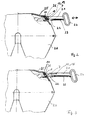
- FIG. 2 the arrangement of such a device 1 on a fifth wheel 20 is shown.
- the side wall 25 of a coupling plate has a passage opening 26 to guide the handle lever 21 to the outside.
- This pull lever 21 is connected via a linkage with a closure device for the kingpin, which is not visible in the illustration shown here.
- the handle lever 21 has a handle 24 with which the handle lever can be moved in the direction of the arrow. Adjacent to the handle lever 21, a safety lever 22 is arranged, which also extends outwardly through the opening 26 and is connected by a spring 23 in the region of the handle 24.
- the device 1 is arranged, wherein the sensor of the device 1 at the bottom of the housing 10th is provided and therefore not visible. Since the handle lever 21 is located under the device 1, this preferably has on its upper side a contact element 12 in the form of a metal plate 13. Instead of a metal plate and a magnet can be used. In the FIG. 2 This metal plate is located under the sensor. This is the position in which the closure device is in the closed position and the handle lever 21 is in its securing position.
- the display device has an optical display element 7 which lights up when the closure position is present ( FIG. 2 ) and goes off when the handle is moved to the open position ( FIG. 3 ).
- the optical display element 7 is mounted laterally on the housing 10 and thus visible from the operating side.
- the device 1 is disposed on the peripheral wall 25 on the fifth wheel plate 20.
- the locking lever 30 is a separate lever that is not connected to the handle lever 21.
- the contact element 12 is likewise arranged in the form of a metal plate 13. Before the handle lever 21 can be moved, previously the locking lever 30 must be moved, as shown in the FIG. 5 is shown. Only then is it possible, the handle lever 21 to open the Locking device on the safety hook 31 on the safety lever 30 to move.
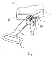
- FIGS. 6 and 7 another embodiment is shown.
- a pivot bearing 27 is provided, in which a pivot lever 14 is mounted with a contact element 12 mounted thereon and thus secures the access lever 21.
- the device 1 according to the invention is arranged, which has the sensor on the underside. In the in FIG. 6 shown position is the handle lever 21 and thus the closure device in the closed position. Accordingly, the optical display 7 lights up.
- the pivot lever 14 Before the access lever 21 can be moved to open the shutter, the pivot lever 14 must be pivoted in the pivot bearing 27 by 90 °, so that the respective leg of the pivot lever is removed from the sensor of the sensor device of the device 1. The device 1 detects thereby the open position and the display element 7 goes out.
- a distance sensor 3b is seen, which is arranged at the top of the housing and the distance to a semi-trailer (not shown) detected.
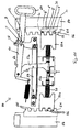
- a bolt coupling 40 is shown having a coupling housing 41 into which the front end of, for example, a drawbar can be inserted.
- the coupling pin 44 In the housing there is an opening for the coupling pin 44, which can be moved in the vertical direction.
- the lever 43 is provided.
- the device 1 according to the invention with the display element 7 is arranged on the left side of the clutch housing 41.
- the functioning is in the FIGS. 9a and 9b shown.
- the device 1 has a mechanical switching element in the form of a securing bolt 18 with the contact element 12 at its free end, which is spring-mounted on the housing 1 and extends through the housing 10 to the outside.
- FIG. 9a shows the open position of the coupling pin 44th
- FIG. 9b shows the closed position in which the coupling pin 44 is displaced relative to the securing pin 18, so that the locking pin 18, driven by the compression spring 19, dips into a recess in the coupling pin 44.
- the respective position can also be detected on the basis of the position of the securing bolt 18, such as a comparison of FIGS. 9a and 9b shows. It is thereby possible to detect the locking position of the coupling bolt 44.
- a displacement device 50 is shown on a towing vehicle (not shown) on a towing vehicle (not shown) on a towing vehicle (not shown) are arranged parallel to each other guide rails 54 with toothed racks 51 and teeth 55.
- the teeth 55 are arranged facing inwards and lie in a common plane.
- a carriage 70 is slidably disposed, the frame in the Figures 10 and 11 not shown.
- a locking device with blocking pieces 52a, b is arranged, which are connected via levers 53a, b with a handle lever 61.
- these Blocking pieces 52a, b from an unlocked position (FIG. FIG. 10 ) into a locked position ( FIG. 11 ) and vice versa.
- the device 1 according to the invention On a wall element 58, through which the pull handle lever 61 is guided, the device 1 according to the invention is arranged.
- a contact element 12 is arranged on the upper side of the handle lever 61.
- the handle lever 61 is fixed with its locking recess 62 on the wall member 58.
- the contact plate 12 is disposed outside the device 1, so that the device 1 detects the unlocked position.
- the contact element 12 is moved under the device 1 so that it can detect the locking position with the sensor unit. Via the visual display 7, a corresponding signal is displayed.
- a device 1 ' accordinging to the invention arranged, the inside has three position sensors 3c and outboard three optical displays 7' has.
- the position sensors 3c Upon engagement of the teeth 56 of the blocking piece 52a in the gaps between the teeth 55 of the rack 51, they are detected by the position sensors 3c.
- the position of the blocking pieces 52a, b also changes, so that not all the teeth 56 of the blocking piece 52a are opposed to a position sensor 3c.
- the optical display elements 7 ' likewise light up correspondingly. On the basis of the number of illuminated display elements, the driver can recognize when passing in which position the slide of the displacement device is located.
Landscapes
- Engineering & Computer Science (AREA)
- Transportation (AREA)
- Mechanical Engineering (AREA)
- Chemical & Material Sciences (AREA)
- Combustion & Propulsion (AREA)
- Lighting Device Outwards From Vehicle And Optical Signal (AREA)
- Mechanical Control Devices (AREA)
- Length Measuring Devices With Unspecified Measuring Means (AREA)
- Measuring Fluid Pressure (AREA)
- Measurement Of Length, Angles, Or The Like Using Electric Or Magnetic Means (AREA)
- Handcart (AREA)
- Arrangement And Mounting Of Devices That Control Transmission Of Motive Force (AREA)
- Measurement Of Distances Traversed On The Ground (AREA)
- Measurement Of Mechanical Vibrations Or Ultrasonic Waves (AREA)
- Devices For Indicating Variable Information By Combining Individual Elements (AREA)
Abstract
Description
Die Erfindung betrifft eine Vorrichtung zum Nachweis und zum Anzeigen der Position von Komponenten von Fahrzeugkupplungen, insbesondere von Sattelkupplungen. Die Erfindung bezieht sich auch auf eine Anordnung einer solchen Vorrichtung an der Außenseite von Sattelkupplungen oder von Verschiebeeinrichtungen einer Sattelkupplung.The invention relates to a device for detecting and displaying the position of components of vehicle clutches, in particular of fifth wheel couplings. The invention also relates to an arrangement of such a device on the outside of fifth wheel couplings or of shifting devices of a fifth wheel.
Aus der
Die Signalübertragung sowie die Energieversorgung der Sensoren erfolgt im Regelfall über Kabelsätze und die Signalauswertung über entsprechende Steuerelektroniken. Der Installationsaufwand für solche Systeme ist groß und steht häufig in einem schlechten Verhältnis zum erzielten Effekt, was einer größeren Verbreitung dieser an sich wünschenswerten und der Sicherheit dienenden Ausstattung hinderlich entgegensteht.The signal transmission as well as the energy supply of the sensors is usually carried out via cable sets and the signal evaluation via corresponding control electronics. The installation cost of such systems is large and is often in a poor ratio to the effect achieved, which hampers greater dissemination of this desirable and security-serving equipment hindering.
Aus der
Unabhängig von dem Vorhandensein von Anzeigeeinrichtungen im Fahrerhaus muss der Fahrer vor Beginn der Fahrt eine visuelle Überprüfung des Fahrzeugs, der Sattelkupplung, der Verschlusseinrichtung etc. durchführen.Regardless of the presence of display devices in the cab, the driver must perform a visual inspection of the vehicle, the fifth wheel, the closure device, etc. before starting the journey.
In der Regel werden mechanische Verschlussanzeigen verwendet, die je nach Ausführung und Lichtverhältnissen besser oder schlechter erkannt werden können. Dies kann den Fahrzeugcheck vor Antritt der Fahrt deutlich erschweren und im Extremfall sogar zu fehlerhaftem Kuppeln führen.As a rule, mechanical shutter displays are used, which can be better or worse recognized depending on the design and lighting conditions. This can significantly complicate the vehicle check before starting the journey and in extreme cases even lead to faulty coupling.
Es ist daher Aufgabe der Erfindung, eine Vorrichtung zum Nachweisen und zum Anzeigen der Position von Komponenten von Fahrzeugkupplungen bereitzustellen, die eine visuelle Überprüfung dieser Komponenten erleichtert.It is therefore an object of the invention to provide a device for detecting and indicating the position of components of vehicle couplings, which facilitates a visual inspection of these components.
Diese Aufgabe wird mit einer Vorrichtung gelöst, die gekennzeichnet ist durch eine kombinierte Sensor- und Anzeigeeinheit, die in einem gemeinsamen Gehäuse angeordnet ist, wobei die Sensoreinheit mindestens einen Sensor und die Anzeigeeinheit mindestens ein Anzeigeelement aufweist.This object is achieved with a device which is characterized by a combined sensor and display unit, which is arranged in a common housing, wherein the sensor unit at least one sensor and the display unit has at least one display element.
Der Vorteil der Vorrichtung besteht darin, dass ein kompaktes Gerät zur Verfügung gestellt wird, das am Ort der Überprüfung platziert werden kann und dort auch ein vorzugsweise optisches oder akustisches Signal abgibt. Eine aufwendige Verkabelung der Sensoreinheit mit einer im Fahrerhaus angeordneten Anzeigeeinrichtung entfällt. Es wird daher ein kostengünstiges Gerät zur Verfügung gestellt, das an den Stellen problemlos angeordnet werden kann, wo eine Überprüfung durchgeführt werden soll. Die visuelle Überprüfung kann durch den Fahrer im Vorbeigehen erfolgen, ohne dass er zusätzliche Hilfsmittel, wie z. B. Taschenlampen etc. benötigt, um beispielsweise den Verschlusszustand einer Sattelkupplung oder die Position einer Verschiebeeinrichtung zu überprüfen.The advantage of the device is that a compact device is provided, which can be placed at the site of the review and there emits a preferably optical or audible signal. A complex cabling of the sensor unit with a arranged in the cab display device is eliminated. There is therefore provided a low-cost device which can be easily arranged at the points where a check should be made. The visual inspection can be done by the driver in passing, without the need for additional aids such. B. flashlights, etc., to check, for example, the closure state of a fifth wheel or the position of a displacement device.
Vorzugsweise weist die kombinierte Sensor- und Anzeigeeinheit eine eigene Spannungsquelle auf, die vorzugsweise im Gehäuse angeordnet ist. Diese Maßnahme trägt ebenfalls zur universellen Einsetzbarkeit der erfindungsgemäßen Vorrichtung bei. Eine Verkabelung zur Stromversorgung entfällt. Als Spannungsquelle können Batterien, Akkus oder z. B. elektrokinematische Generatoren verwendet werden.Preferably, the combined sensor and display unit has its own voltage source, which is preferably arranged in the housing. This measure also contributes to the universal applicability of the device according to the invention. Cabling to the power supply is eliminated. As a voltage source batteries, rechargeable batteries or z. B. electrokinematical generators can be used.
Vorzugsweise weist die kombinierte Sensor- und Anzeigeeinheit eine elektronische Auswerteeinheit auf. Mit dieser Auswerteeinheit kann nicht nur das Sensorsignal dahingehend ausgewertet werden, ob ein Verschlusszustand vorliegt oder nicht (Ja/Nein-Signal), sondern eine solche Auswerteeinheit ermöglicht es auch, den Zustand der Energieversorgung (z. B. Akku oder Batterie) auszuwerten. Vorzugsweise kann die Vorrichtung auch mindestens einen Abstandssensor aufweisen. Mit einer mit einem solchen Abstandssensor ausgerüstete Vorrichtung ist es beispielsweise möglich, an einer Sattelkupplung die korrekte Position eines Aufliegers auf der Sattelkupplung zu überprüfen. Anhand des ermittelten Abstandes von der Vorrichtung zur Unterseite des Aufliegers kann festgestellt werden, ob dieser sich in der vorgeschriebenen Position befindet, in der der Königszapfen in die Verschlusseinrichtung der Sattelkupplung eingreift.The combined sensor and display unit preferably has an electronic evaluation unit. With this evaluation unit, not only the sensor signal can be evaluated as to whether a shutter state exists or not (yes / no signal), but such an evaluation unit also makes it possible to evaluate the state of the power supply (eg battery or battery). Preferably, the device may also comprise at least one distance sensor. With a device equipped with such a distance sensor, it is possible, for example, to check the correct position of a semitrailer on the fifth wheel on a fifth wheel. On the basis of the determined distance from the device to the underside of the trailer can be determined whether it is in the prescribed position in which engages the kingpin in the closure device of the fifth wheel.
Als Sensoren können induktive Sensoren, Magnetsensoren, Kraftsensoren, Drucksensoren oder Reedsensoren in Betracht kommen. Vorzugsweise arbeiten die Sensoren berührungslos, wobei elektromagnetische Sensoren bevorzugt sind.As sensors inductive sensors, magnetic sensors, force sensors, pressure sensors or reed sensors can be considered. Preferably, the sensors operate without contact, with electromagnetic sensors being preferred.
Je nach Einsatzort kann der Sensor auch ein Schaltelement, insbesondere ein mechanisches Schaltelement, aufweisen. Eine derartige Ausführung ist beispielsweise zweckmäßig beim Einsatz der erfindungsgemäßen Vorrichtung an Bolzenkupplungen.Depending on the place of use, the sensor may also have a switching element, in particular a mechanical switching element. Such an embodiment is useful, for example, when using the device according to the invention on bolt couplings.
Die Anzeigeeinheit weist vorzugsweise ein am Gehäuse angeordnetes optisches Anzeigeelement auf. Dies kann z. B. eine Lampe, insbesondere eine LED-Anzeige sein. Hierbei ist es bevorzugt, wenn dieses optische Anzeigeelement derart am Gehäuse angeordnet ist, dass es entsprechend der Position der Vorrichtung am Fahrzeug beim Vorgehen des Fahrers von diesem problemlos wahrgenommen werden kann.The display unit preferably has an optical display element arranged on the housing. This can be z. B. a lamp, in particular an LED display. In this case, it is preferred if this optical display element is arranged on the housing in such a way that, in accordance with the position of the device on the vehicle, it can be easily perceived by the driver when the driver does so.
Die Anzeigeeinheit kann ausschließlich oder zusätzlich ein akustisches Anzeigeelement und/oder ein mechanisches Anzeigeelement aufweisen. Als mechanische Anzeigeelemente kommen Winker, Stifte oder ähnliches in Frage. Bei den akustischen Anzeigeelementen sind Piepser oder Summer bevorzugt. Die Anzeige am Anzeigeelement kann permanent erfolgen, beispielsweise durch ein Dauerlicht oder Dauerton. Die Anzeige kann aber auch nicht permanent ausgelegt sein und z. B. in Form eines Blinklichtes oder dergleichen.The display unit may exclusively or additionally comprise an acoustic display element and / or a mechanical display element. As mechanical display elements come Winker, pins or the like in question. In the acoustic display elements are Beeper or buzzer preferred. The display on the display element can be permanent, for example, by a steady light or continuous tone. The display can not be designed to be permanent and z. B. in the form of a flashing light or the like.
Es ist insbesondere vorgesehen, den Verschlusszustand z. B. einer Sattelkupplung durch ein optisches oder akustisches Signal anzuzeigen. Auch kann es zweckmäßig sein, die Offenstellung signalmäßig anzuzeigen. Welche Art der Anzeige gewählt wird, hängt von der Art der zu detektierenden Position der Fahrzeugkomponente und/oder deren Anordnung am Fahrzeug ab.It is particularly provided, the closure state z. B. a fifth wheel by an optical or acoustic signal. It may also be expedient to signal the open position. Which type of display is selected depends on the type of position of the vehicle component to be detected and / or its arrangement on the vehicle.
Die erfindungsgemäße Anordnung der beschriebenen Vorrichtung sieht vor, dass die Vorrichtung an der Außenseite einer Sattelkupplung oder einer Verschiebeeinrichtung einer Sattelkupplung und benachbart zu einem Handbetätigungselement einer Verschluss- oder Verriegelungseinrichtung angeordnet ist, wobei ein Kontaktelement der Art an dem Handbetätigungselement angeordnet ist oder von dem Handbetätigungselement betätigbar ist, dass es in Schließ- und Verriegelungsstellung mit dem Sensor der Sensoreinheit zusammenwirkt.The inventive arrangement of the described device provides that the device is arranged on the outside of a fifth wheel or a sliding device of a fifth wheel and adjacent to a manual actuating element of a locking or locking device, wherein a contact element of the type is arranged on the manual actuating element or actuated by the manual actuating element is that it interacts in the closed and locked position with the sensor of the sensor unit.
Die Außenseite einer Sattelkupplung oder einer Verschiebeeinrichtung meint einen geeigneten Ort, der von außen leicht einsehbar ist, so dass die Anzeigeeinrichtung beim Vorbeigehen am Fahrzeug ohne weiteres erkennbar ist. Die Anordnung an oder in der Nähe eines Handbetätigungselementes bietet den Vorteil, dass es sich hier um einen Ort handelt, der ohnehin für den Fahrer zugänglich sein muss, weil er das Handbetätigungselement beispielsweise zum Verriegeln einer Sattelkupplung betätigen muss. Derartige Orte sind leicht einsehbar, so dass dort die Vorrichtung bzw. deren Anzeigeeinrichtung mühelos erkennbar ist.The outside of a fifth wheel or a displacement device means a suitable location, which is easily visible from the outside, so that the display device is easily recognizable when passing the vehicle. The arrangement on or in the vicinity of a manual actuating element has the advantage that this is a location that has to be accessible to the driver anyway, because he has to operate the manual operating element, for example, to lock a fifth wheel. Such places are easily visible, so that there the device or its display device is easily recognizable.
Das Handbetätigungselement kann ein Zuggriffhebel oder ein Sicherungshebel eines Zuggriffhebels sein.The manual operating element may be a pull lever or a safety lever of a handle lever.
Als Kontaktelement ist eine Metallplatte oder ein Magnet bevorzugt, die an dem Handbetätigungselement befestigt sind. Durch eine Bewegung des Handbetätigungselementes wird dieses Kontaktelement in dem Bereich des Sensors der Vorrichtung bewegt bzw. vom Sensor entfernt, so dass zwei unterschiedliche Stellungen des Handbetätigungselementes und damit auch der damit verbundenen Verriegelungseinrichtung detektiert werden kann.As a contact element, a metal plate or a magnet is preferred, which are attached to the manual actuating element. By a movement of the manual actuating element, this contact element is moved in the region of the sensor of the device or removed from the sensor, so that two different positions of the manual actuating element and thus also the associated locking device can be detected.
Das Kontaktelement kann auch auf einem Schwenkelement angeordnet sein, das ein Handbetätigungselement ist. Ein solches Handbetätigungselement dient beispielsweise als Verriegelungselement für einen Zuggriffhebel, mit dem die Verschlusseinrichtung einer Sattelkupplung betätigt wird. Das Kontaktelement wirkt mit dem Sensor der Vorrichtung zusammen, wenn es in den Bereich des Sensors verschwenkt wird.The contact element can also be arranged on a pivoting element, which is a manual actuating element. Such a manual actuating element serves, for example, as a locking element for a pull lever, with which the closure device of a fifth wheel is actuated. The contact element cooperates with the sensor of the device when it is pivoted into the region of the sensor.
Die erfindungsgemäße Vorrichtung kann auch an der Außenseite einer Bolzenkupplung benachbart zum Kupplungsbolzen angeordnet sein, der in Schließstellung mit dem Sensor der Sensoreinheit zusammenwirkt.The device according to the invention can also be arranged on the outside of a bolt coupling adjacent to the coupling bolt, which cooperates in the closed position with the sensor of the sensor unit.
Der Sensor weist bei dieser Ausführung ein Schaltelement auf, das vom Kupplungsbolzen betätigbar ist. Dieses Schaltelement ist mit der Sensoreinheit in der Weise verknüpft, dass aus der Position des Schaltelementes auf den Verschlusszustand der Bolzenkupplung geschlossen werden kann.The sensor has in this embodiment, a switching element which is actuated by the coupling pin. This switching element is linked to the sensor unit in such a way that it can be concluded from the position of the switching element on the closure state of the bolt coupling.
Eine weitere Anordnung der Vorrichtung sieht die Anbringung an der Außenseite einer Verschiebeeinrichtung, die eine Zahnleiste und auf einem eine Sattelkupplung tragenden Schlitten Blockierstücke aufweist, und benachbart zu einem Blockierstück vor, das in Verriegelungsstellung mit dem Sensor der Sensoreinheit zusammenwirkt. Es ist mit der Vorrichtung möglich, an Ort und Stelle die exakte Position der Verschiebeeinrichtung, d. h. des Schlittens anzuzeigen. Zu diesem Zweck kann die Anzeigeeinrichtung mehrere Anzeigeelemente oder auch eine digitale oder analoge Anzeige aufweisen, die die Position beispielsweise in Zentimetern von einem Fixpunkt angibt.A further arrangement of the device provides for attachment to the outside of a displacement device having a rack and on a fifth wheel carrying slide blocking pieces, and adjacent to a blocking piece, which cooperates in the locking position with the sensor of the sensor unit. It is possible with the device, in place, the exact position of the displacement device, d. H. of the carriage. For this purpose, the display device may comprise a plurality of display elements or a digital or analog display indicating the position, for example, in centimeters from a fixed point.
Beispielhafte Ausführungsformen der Erfindung werden nachfolgend anhand der Zeichnungen näher erläutert. Es zeigen:
Figur 1- eine schematische Darstellung der erfindungsgemäßen Vorrichtung,
- Fign. 2+3
- die Anordnung der erfindungsgemäßen Vorrichtung an einer Sattelkupplung gemäß einer ersten Ausführungsform,
- Fign. 4+5
- die Anordnung der erfindungsgemäßen Vorrichtung an einer Sattelkupplung gemäß einer zweiten Ausführungsform,
- Fign. 6+7
- die Anordnung an einer Sattelkupplung gemäß einer dritten Ausführungsform,
- Figur 8
- die Anordnung der Vorrichtung an einer Bolzenkupplung,
- Fign. 9a+9b
- eine vergrößerte schematische Darstellung der Vorrichtung an einer Bolzenkupplung,
- Fign. 10+11
- die Anordnung der erfindungsgemäßen Vorrichtung an einer Verschiebeeinrichtung.
- FIG. 1
- a schematic representation of the device according to the invention,
- FIGS. 2 + 3
- the arrangement of the device according to the invention on a fifth wheel according to a first embodiment,
- FIGS. 4 + 5
- the arrangement of the device according to the invention on a fifth wheel according to a second embodiment,
- FIGS. 6 + 7
- the arrangement on a fifth wheel according to a third embodiment,
- FIG. 8
- the arrangement of the device on a bolt coupling,
- FIGS. 9a + 9b
- an enlarged schematic representation of the device on a bolt coupling,
- FIGS. 10 + 11
- the arrangement of the device according to the invention on a displacement device.
In der
In der
Der Zuggriffhebel 21 besitzt einen Griff 24, mit dem der Zuggriffhebel in Pfeilrichtung bewegt werden kann. Benachbart zum Zuggriffhebel 21 ist ein Sicherungshebel 22 angeordnet, der sich ebenfalls nach außen durch die Öffnung 26 erstreckt und mittels einer Feder 23 im Bereich des Griffs 24 verbunden ist.The
In der Durchführungsöffnung 26 ist die Vorrichtung 1 angeordnet, wobei der Sensor der Vorrichtung 1 an der Unterseite des Gehäuses 10 vorgesehen ist und daher nicht sichtbar ist. Da sich der Zuggriffhebel 21 unter der Vorrichtung 1 befindet, besitzt dieser vorzugsweise an seiner Oberseite ein Kontaktelement 12 in Form einer Metallplatte 13. Anstelle einer Metallplatte kann auch ein Magnet verwendet werden. In der
Durch Herausziehen des Zuggriffhebels 21 wird dieser in eine Position bewegt, die es ermöglicht, den Zuggriffhebel auch seitlich zu versetzen und die Verschlusseinrichtung des Königszapfens zu öffnen. Hierbei wird das Kontaktelement 12 von der Vorrichtung 1 und somit vom Sensor wegbewegt, was durch die Anzeigeeinrichtung kenntlich gemacht werden kann.By pulling out the
In den
In der
In den
Bevor der Zugriffhebel 21 zum Öffnen des Verschlusses bewegt werden kann, muss der Schwenkhebel 14 in der Schwenklagerung 27 um 90° verschwenkt werden, so dass der betreffende Schenkel des Schwenkhebels vom Sensor der Sensoreinrichtung der Vorrichtung 1 entfernt wird. Die Vorrichtung 1 erkennt dadurch die Offenstellung und das Anzeigeelement 7 erlischt.Before the
In den
In der
An der linken Seite des Kupplungsgehäuses 41 ist die erfindungsgemäße Vorrichtung 1 mit dem Anzeigeelement 7 angeordnet. Die Funktionsweise wird in den
Die Vorrichtung 1 besitzt ein mechanisches Schaltelement in Form eines Sicherungsbolzens 18 mit dem Kontaktelement 12 an seinem freien Ende, der federgelagert am Gehäuse 1 angeordnet ist und sich durch das Gehäuse 10 nach außen erstreckt.
In den
Auf den Führungsschienen 54 ist ein Schlitten 70 verschiebbar angeordnet, dessen Rahmen in den
Auf dem Schlitten ist eine Verriegelungseinrichtung mit Blockierstücken 52a,b angeordnet, die über Hebel 53a,b mit einem Zuggriffhebel 61 verbunden sind. Mittels des Zuggriffhebels 61 werden diese Blockierstücke 52a,b von einer entriegelten Position (
Wenn, wie in
In den
- 1, 1'1, 1 '
- Vorrichtungcontraption
- 22
- Anzeigeeinheitdisplay unit
- 33
- Sensoreinheitsensor unit
- 3a3a
- Sensorsensor
- 3b3b
- Sensor (Abstandssensor)Sensor (distance sensor)
- 3c3c
- Sensor (Positionssensor)Sensor (position sensor)
- 44
- Auswerteeinheitevaluation
- 55
- Spannungsquellevoltage source
- 66
- akustisches Anzeigeelementacoustic indicator
- 77
- optisches Anzeigeelementoptical display element
- 1010
- Gehäusecasing
- 1212
- Kontaktelementcontact element
- 1313
- Metallplattemetal plate
- 1414
- Schwenkelementpivoting element
- 1717
- Schaltelementswitching element
- 1818
- Sicherungsbolzensafety bolt
- 1919
- Druckfedercompression spring
- 2020
- Sattelkupplungfifth wheel
- 2121
- Zuggriffhebelpull lever
- 2222
- Sicherungshebelsafety lever
- 2323
- Federfeather
- 2424
- GriffHandle
- 2525
- Umfangswandperipheral wall
- 2626
- Öffnungopening
- 2727
- Schwenklagerpivot bearing
- 3030
- Sicherungshebelsafety lever
- 3131
- Sicherungshakensafety hook
- 4040
- Bolzenkupplungpin coupling
- 4141
- Kupplungsgehäuseclutch housing
- 4343
- Sicherungshebelsafety lever
- 4444
- Kupplungsbolzencoupling pin
- 5050
- Verschiebeeinrichtungshifter
- 5151
- Zahnleisterack
- 52a,b52a, b
- Blockierstückshim
- 53a,b53a, b
- Hebellever
- 5454
- Führungsschieneguide rail
- 5555
- Zahntooth
- 5656
- Zahntooth
- 5757
- Federfeather
- 5858
- Wandelementwall element
- 6161
- Zuggriffhebelpull lever
- 6262
- Rastausnehmungrecess
- 6363
- Rastanordnungdetent arrangement
- 6464
- GriffHandle
- 6565
- 6666
- Zahntooth
- 7070
- Schlittencarriage
Claims (12)
dadurch gekennzeichnet,
dass der mindestens eine Sensor (3a, 3b), das mindestens eine Anzeigeelement (6, 7) und die Spannungsquelle (5) in einem gemeinsamen Gehäuse (10) einer kombinierten Sensor- und Anzeigeeinheit (2, 3) angeordnet sind, welche an der Außenseite der Sattelkupplung (20) benachbart zu dem Handbetätigungselement einer Verschluss- oder Verriegelungseinrichtung angeordnet ist.Arrangement of a device (1, 1 ') for detecting and displaying the position of components of vehicle couplings on a fifth wheel (20), wherein the device (' 1, 1 ') has at least one sensor (3a, 3b) and at least one indicator element ( 6, 7) and a separate voltage source (5), and a contact element (12) is arranged on a hand-operated element, or can be actuated by a hand-operated element such that it interacts with the sensor (3a) in the closed or locked position,
characterized,
in that the at least one sensor (3a, 3b), the at least one display element (6, 7) and the voltage source (5) are arranged in a common housing (10) of a combined sensor and display unit (2, 3) which is connected to the Outside of the fifth wheel (20) adjacent to the manual actuating element of a locking or locking device is arranged.
Priority Applications (1)
| Application Number | Priority Date | Filing Date | Title |
|---|---|---|---|
| PL09162089T PL2090500T3 (en) | 2005-03-24 | 2006-03-21 | Device for detecting and displaying the position of components of vehicle couplings |
Applications Claiming Priority (2)
| Application Number | Priority Date | Filing Date | Title |
|---|---|---|---|
| DE102005014977A DE102005014977B4 (en) | 2005-03-24 | 2005-03-24 | Device for detecting and displaying the position of components of vehicle clutches |
| EP06723569A EP1861306B1 (en) | 2005-03-24 | 2006-03-21 | Device for detecting and displaying the position of components of vehicle couplings |
Related Parent Applications (2)
| Application Number | Title | Priority Date | Filing Date |
|---|---|---|---|
| EP06723569A Division EP1861306B1 (en) | 2005-03-24 | 2006-03-21 | Device for detecting and displaying the position of components of vehicle couplings |
| EP06723569.7 Division | 2006-03-21 |
Publications (2)
| Publication Number | Publication Date |
|---|---|
| EP2090500A1 true EP2090500A1 (en) | 2009-08-19 |
| EP2090500B1 EP2090500B1 (en) | 2010-09-29 |
Family
ID=36599090
Family Applications (3)
| Application Number | Title | Priority Date | Filing Date |
|---|---|---|---|
| EP09162089A Active EP2090500B1 (en) | 2005-03-24 | 2006-03-21 | Device for detecting and displaying the position of components of vehicle couplings |
| EP09162092A Active EP2093134B1 (en) | 2005-03-24 | 2006-03-21 | Device for documenting and displaying the position of components of vehicle couplings |
| EP06723569A Not-in-force EP1861306B1 (en) | 2005-03-24 | 2006-03-21 | Device for detecting and displaying the position of components of vehicle couplings |
Family Applications After (2)
| Application Number | Title | Priority Date | Filing Date |
|---|---|---|---|
| EP09162092A Active EP2093134B1 (en) | 2005-03-24 | 2006-03-21 | Device for documenting and displaying the position of components of vehicle couplings |
| EP06723569A Not-in-force EP1861306B1 (en) | 2005-03-24 | 2006-03-21 | Device for detecting and displaying the position of components of vehicle couplings |
Country Status (12)
| Country | Link |
|---|---|
| US (1) | US7932816B2 (en) |
| EP (3) | EP2090500B1 (en) |
| CN (1) | CN101180204B (en) |
| AR (1) | AR055754A1 (en) |
| AT (3) | ATE508931T1 (en) |
| BR (1) | BRPI0609431A2 (en) |
| CA (1) | CA2602033C (en) |
| DE (3) | DE102005014977B4 (en) |
| EA (1) | EA011966B1 (en) |
| ES (3) | ES2353366T3 (en) |
| PL (3) | PL1861306T3 (en) |
| WO (1) | WO2006100025A1 (en) |
Families Citing this family (16)
| Publication number | Priority date | Publication date | Assignee | Title |
|---|---|---|---|---|
| US8421640B1 (en) * | 2010-06-07 | 2013-04-16 | Edward Wayne Larson | Tractor lift detection system for gantry cranes |
| DE102011085338A1 (en) * | 2011-10-27 | 2013-05-02 | Rockinger Agriculture Gmbh | Remote indicator for trailer hitch |
| US9723692B2 (en) * | 2015-05-20 | 2017-08-01 | Saf-Holland, Inc | Fifth wheel coupling detection system with inspection and indication lighting arrangement |
| US9862242B2 (en) | 2015-12-21 | 2018-01-09 | Jason P. Lurie | Coupling system |
| EP3379222B1 (en) | 2017-03-22 | 2020-12-30 | Methode Electronics Malta Ltd. | Magnetoelastic based sensor assembly |
| US10406874B2 (en) | 2017-09-27 | 2019-09-10 | Roger D. McKelvey | Fifth wheel trailer lock |
| US11135882B2 (en) | 2018-02-27 | 2021-10-05 | Methode Electronics, Inc. | Towing systems and methods using magnetic field sensing |
| US11084342B2 (en) | 2018-02-27 | 2021-08-10 | Methode Electronics, Inc. | Towing systems and methods using magnetic field sensing |
| WO2019168565A1 (en) | 2018-02-27 | 2019-09-06 | Methode Electronics,Inc. | Towing systems and methods using magnetic field sensing |
| US11014417B2 (en) | 2018-02-27 | 2021-05-25 | Methode Electronics, Inc. | Towing systems and methods using magnetic field sensing |
| US11491832B2 (en) | 2018-02-27 | 2022-11-08 | Methode Electronics, Inc. | Towing systems and methods using magnetic field sensing |
| US11221262B2 (en) | 2018-02-27 | 2022-01-11 | Methode Electronics, Inc. | Towing systems and methods using magnetic field sensing |
| US11731471B2 (en) | 2018-04-27 | 2023-08-22 | Fontaine Fifth Wheel Company | Methods and systems for monitoring coupling of fifth wheels to kingpins |
| US11524536B2 (en) | 2019-02-14 | 2022-12-13 | Fontaine Fifth Wheel Company | Apparatuses, systems, and methods for determining and verifying operational states of fifth wheels |
| US20210125433A1 (en) * | 2019-10-23 | 2021-04-29 | Brandon Gonzalez | Safety system for coupling truck and trailer |
| EP4257462A1 (en) | 2022-04-07 | 2023-10-11 | Sampa Otomotiv Sanayi Ve Ticaret Anonim Sirketi | Fifth wheel with an automatically moving adjusting member and method thereof |
Citations (5)
| Publication number | Priority date | Publication date | Assignee | Title |
|---|---|---|---|---|
| EP0509137A1 (en) * | 1991-04-16 | 1992-10-21 | ROCKINGER Spezialfabrik für Anhängerkupplungen GmbH & Co. | Saddle coupling device keyword: operating handle |
| US5861802A (en) * | 1996-03-04 | 1999-01-19 | Holland Hitch Company | Fifth wheel hitch coupling control system |
| US6100794A (en) * | 1999-02-18 | 2000-08-08 | Hillier; Terrence E. | Fifth wheel coupling safety system |
| US6222457B1 (en) * | 1999-10-12 | 2001-04-24 | Stephen Scott Keneally | Electronic trailer hitching system |
| EP1396417A1 (en) * | 2002-09-06 | 2004-03-10 | Jost-Werke GmbH & Co. KG | Device for indicating the closure state of a fifth wheel coupling and arrangement of sensors |
Family Cites Families (17)
| Publication number | Priority date | Publication date | Assignee | Title |
|---|---|---|---|---|
| US3868127A (en) * | 1974-07-26 | 1975-02-25 | Pullman Inc | Engaged kingpin detector assembly for fifth wheel plate |
| DE3226360C2 (en) * | 1982-07-14 | 1986-04-24 | Rockinger Spezialfabrik für Anhängerkupplungen GmbH & Co, 8000 München | trailer hitch |
| DE3909087A1 (en) * | 1989-03-20 | 1990-09-27 | Rockinger Spezial Fab Joh | REMOTE DISPLAY DEVICE FOR VEHICLE TRAILER COUPLINGS |
| AT392940B (en) * | 1989-12-14 | 1991-07-10 | Scharmueller Josef Ing | Trailing coupling, in particular for tractors |
| US5477207A (en) * | 1993-10-04 | 1995-12-19 | C & M Safety Systems, Inc. | Warning device for a vehicle and trailer coupling system |
| US5617072A (en) * | 1994-12-07 | 1997-04-01 | Rockin' Chair Truckers Co. | Position signaling apparatus |
| IT1286196B1 (en) * | 1996-08-08 | 1998-07-08 | C B M Spa | ELECTRONICALLY MANAGED CONTROL AND SAFETY SYSTEM FOR CONNECTION BETWEEN A TRACTOR AND A TOWED VEHICLE |
| US5988666A (en) * | 1997-07-18 | 1999-11-23 | Holland Hitch Company | Fifth wheel hitch release |
| US6285278B1 (en) * | 2000-01-28 | 2001-09-04 | Holland Hitch Company | Electronic system for monitoring a fifth wheel hitch |
| US6592230B2 (en) * | 1997-10-16 | 2003-07-15 | Holland Hitch Company | Truck rearview mirror assembly having a display for displaying trailer coupling status information |
| DE29722370U1 (en) * | 1997-12-18 | 1998-04-02 | Brecht Thomas | Safety bolts - latching indicator for trucks - trailers - couplings |
| DE19820139B4 (en) * | 1998-05-06 | 2008-05-29 | Georg Fischer Verkehrstechnik Gmbh | Device for monitoring the proper locking and securing of a fifth wheel of a semitrailer vehicle |
| US6011492A (en) * | 1998-06-30 | 2000-01-04 | Garesche; Carl E. | Vehicle warning system for visual communication of hazardous traffic conditions |
| US6452485B1 (en) * | 2000-01-28 | 2002-09-17 | The Holland Group, Inc. | Electronic system for monitoring a fifth wheel hitch |
| US6736420B2 (en) * | 2000-03-03 | 2004-05-18 | Jost International Corporation | Carrier assembly for a fifth wheel |
| JP2002331971A (en) * | 2001-05-07 | 2002-11-19 | Hino Motors Ltd | Slide type coupling traction device |
| DE102005031365B4 (en) * | 2005-06-30 | 2008-04-30 | Jost-Werke Gmbh | Device for detecting and displaying the position of components of vehicle clutches |
-
2005
- 2005-03-24 DE DE102005014977A patent/DE102005014977B4/en not_active Expired - Fee Related
-
2006
- 2006-03-21 AT AT09162092T patent/ATE508931T1/en active
- 2006-03-21 WO PCT/EP2006/002555 patent/WO2006100025A1/en active Application Filing
- 2006-03-21 DE DE502006007996T patent/DE502006007996D1/en active Active
- 2006-03-21 CA CA2602033A patent/CA2602033C/en not_active Expired - Fee Related
- 2006-03-21 EA EA200702061A patent/EA011966B1/en not_active IP Right Cessation
- 2006-03-21 EP EP09162089A patent/EP2090500B1/en active Active
- 2006-03-21 ES ES09162089T patent/ES2353366T3/en active Active
- 2006-03-21 PL PL06723569T patent/PL1861306T3/en unknown
- 2006-03-21 PL PL09162092T patent/PL2093134T3/en unknown
- 2006-03-21 BR BRPI0609431-7A patent/BRPI0609431A2/en not_active Application Discontinuation
- 2006-03-21 ES ES06723569T patent/ES2333160T3/en active Active
- 2006-03-21 AT AT06723569T patent/ATE444889T1/en active
- 2006-03-21 PL PL09162089T patent/PL2090500T3/en unknown
- 2006-03-21 EP EP09162092A patent/EP2093134B1/en active Active
- 2006-03-21 US US11/887,032 patent/US7932816B2/en not_active Expired - Fee Related
- 2006-03-21 CN CN2006800095467A patent/CN101180204B/en active Active
- 2006-03-21 DE DE502006005031T patent/DE502006005031D1/en active Active
- 2006-03-21 ES ES09162092T patent/ES2362400T3/en active Active
- 2006-03-21 EP EP06723569A patent/EP1861306B1/en not_active Not-in-force
- 2006-03-21 AT AT09162089T patent/ATE482871T1/en active
- 2006-03-27 AR ARP060101165A patent/AR055754A1/en active IP Right Grant
Patent Citations (6)
| Publication number | Priority date | Publication date | Assignee | Title |
|---|---|---|---|---|
| EP0509137A1 (en) * | 1991-04-16 | 1992-10-21 | ROCKINGER Spezialfabrik für Anhängerkupplungen GmbH & Co. | Saddle coupling device keyword: operating handle |
| US5861802A (en) * | 1996-03-04 | 1999-01-19 | Holland Hitch Company | Fifth wheel hitch coupling control system |
| US6100794A (en) * | 1999-02-18 | 2000-08-08 | Hillier; Terrence E. | Fifth wheel coupling safety system |
| US6222457B1 (en) * | 1999-10-12 | 2001-04-24 | Stephen Scott Keneally | Electronic trailer hitching system |
| EP1396417A1 (en) * | 2002-09-06 | 2004-03-10 | Jost-Werke GmbH & Co. KG | Device for indicating the closure state of a fifth wheel coupling and arrangement of sensors |
| DE10241904A1 (en) * | 2002-09-06 | 2004-03-11 | Jost-Werke Gmbh & Co Kg | Sensor for kingpin |
Also Published As
| Publication number | Publication date |
|---|---|
| ATE508931T1 (en) | 2011-05-15 |
| EP2090500B1 (en) | 2010-09-29 |
| PL1861306T3 (en) | 2010-03-31 |
| CA2602033A1 (en) | 2006-09-28 |
| ATE444889T1 (en) | 2009-10-15 |
| DE102005014977B4 (en) | 2008-08-21 |
| ES2333160T3 (en) | 2010-02-17 |
| PL2093134T3 (en) | 2011-10-31 |
| WO2006100025A1 (en) | 2006-09-28 |
| ES2353366T3 (en) | 2011-03-01 |
| EP2093134A1 (en) | 2009-08-26 |
| BRPI0609431A2 (en) | 2010-04-06 |
| US7932816B2 (en) | 2011-04-26 |
| EA200702061A1 (en) | 2008-06-30 |
| EP2093134B1 (en) | 2011-05-11 |
| ATE482871T1 (en) | 2010-10-15 |
| EP1861306B1 (en) | 2009-10-07 |
| EA011966B1 (en) | 2009-06-30 |
| CN101180204B (en) | 2010-08-04 |
| CN101180204A (en) | 2008-05-14 |
| US20080150745A1 (en) | 2008-06-26 |
| EP1861306A1 (en) | 2007-12-05 |
| PL2090500T3 (en) | 2011-03-31 |
| DE102005014977A1 (en) | 2006-10-05 |
| AR055754A1 (en) | 2007-09-05 |
| CA2602033C (en) | 2012-12-18 |
| DE502006007996D1 (en) | 2010-11-11 |
| ES2362400T3 (en) | 2011-07-04 |
| DE502006005031D1 (en) | 2009-11-19 |
Similar Documents
| Publication | Publication Date | Title |
|---|---|---|
| EP2090500B1 (en) | Device for detecting and displaying the position of components of vehicle couplings | |
| EP1896317B1 (en) | Device for detecting and for indicating the position of components of vehicle couplings | |
| DE102004045663B4 (en) | Displacement device for a fifth wheel | |
| EP2508393B1 (en) | Device with a camera unit | |
| DE102008028434B4 (en) | Tail lift with remote control | |
| EP2152553B1 (en) | Operating device for a vehicle having an automatic transmission and an electrically actuated parking brake system | |
| DE112017006055T5 (en) | Device for opening and closing a vehicle door | |
| DE102010039333A1 (en) | Belt buckle with status transmitter | |
| DE102016214004A1 (en) | Checking the integrity of a vehicle network | |
| EP3060424B1 (en) | Locking indicator for a vehicle seat, vehicle seat, motor vehicle, and method for locking a vehicle seat | |
| DE202005005191U1 (en) | Detection and position indicating device for coupling components has combined sensor and indicator unit in common housing | |
| DE202017100896U1 (en) | Motor vehicle door lock status system | |
| DE102019113503A1 (en) | Coupling system for a mobile working machine and retrofitting system for a trailer coupling of a mobile working machine and mobile working machine with the coupling system | |
| DE102009037634A1 (en) | Elevator and method for securing an elevator | |
| DE202006006864U1 (en) | Device for locking a sliding door | |
| DE102009036769A1 (en) | Testing device i.e. testing stand, for testing motor vehicle transmission, has connection element conveyed from resting position into fixing position, in which form-fit mechanical coupling with coupling element exists, using feeding device | |
| DE10141139C1 (en) | Safety arrangement, for agricultural machine, has protective cladding, circuit element, safety switch, coded actuator, guide part, maintenance key and recess | |
| DE10306361B4 (en) | Door handle assembly for a motor vehicle door | |
| DE102018206235A1 (en) | Mounting device for mounting sensors on a rail vehicle | |
| DE3702479A1 (en) | Antitheft device for the gear lever in a manual transmission system | |
| DE102015009172A1 (en) | Locking device for a tiltable cab of a commercial vehicle | |
| EP3621046A1 (en) | Alarm device for lorries | |
| DE102019135862A1 (en) | Sensor system with emergency feature for a vehicle | |
| DE102018004342A1 (en) | System for representing the state of at least one cargo door of an aircraft | |
| DE102017112371A1 (en) | Sensor system for monitoring automatic doors and automatic door |
Legal Events
| Date | Code | Title | Description |
|---|---|---|---|
| PUAI | Public reference made under article 153(3) epc to a published international application that has entered the european phase |
Free format text: ORIGINAL CODE: 0009012 |
|
| 17P | Request for examination filed |
Effective date: 20090605 |
|
| AC | Divisional application: reference to earlier application |
Ref document number: 1861306 Country of ref document: EP Kind code of ref document: P |
|
| AK | Designated contracting states |
Kind code of ref document: A1 Designated state(s): AT BE BG CH CY CZ DE DK EE ES FI FR GB GR HU IE IS IT LI LT LU LV MC NL PL PT RO SE SI SK TR |
|
| GRAP | Despatch of communication of intention to grant a patent |
Free format text: ORIGINAL CODE: EPIDOSNIGR1 |
|
| RIC1 | Information provided on ipc code assigned before grant |
Ipc: B62D 53/08 20060101AFI20100329BHEP |
|
| GRAS | Grant fee paid |
Free format text: ORIGINAL CODE: EPIDOSNIGR3 |
|
| GRAA | (expected) grant |
Free format text: ORIGINAL CODE: 0009210 |
|
| AC | Divisional application: reference to earlier application |
Ref document number: 1861306 Country of ref document: EP Kind code of ref document: P |
|
| AK | Designated contracting states |
Kind code of ref document: B1 Designated state(s): AT BE BG CH CY CZ DE DK EE ES FI FR GB GR HU IE IS IT LI LT LU LV MC NL PL PT RO SE SI SK TR |
|
| REG | Reference to a national code |
Ref country code: GB Ref legal event code: FG4D Free format text: NOT ENGLISH |
|
| REG | Reference to a national code |
Ref country code: CH Ref legal event code: EP |
|
| REG | Reference to a national code |
Ref country code: IE Ref legal event code: FG4D Free format text: LANGUAGE OF EP DOCUMENT: GERMAN |
|
| REF | Corresponds to: |
Ref document number: 502006007996 Country of ref document: DE Date of ref document: 20101111 Kind code of ref document: P |
|
| REG | Reference to a national code |
Ref country code: NL Ref legal event code: T3 |
|
| REG | Reference to a national code |
Ref country code: CH Ref legal event code: NV Representative=s name: R. A. EGLI & CO. PATENTANWAELTE |
|
| REG | Reference to a national code |
Ref country code: SE Ref legal event code: TRGR |
|
| PG25 | Lapsed in a contracting state [announced via postgrant information from national office to epo] |
Ref country code: LT Free format text: LAPSE BECAUSE OF FAILURE TO SUBMIT A TRANSLATION OF THE DESCRIPTION OR TO PAY THE FEE WITHIN THE PRESCRIBED TIME-LIMIT Effective date: 20100929 Ref country code: FI Free format text: LAPSE BECAUSE OF FAILURE TO SUBMIT A TRANSLATION OF THE DESCRIPTION OR TO PAY THE FEE WITHIN THE PRESCRIBED TIME-LIMIT Effective date: 20100929 |
|
| LTIE | Lt: invalidation of european patent or patent extension |
Effective date: 20100929 |
|
| PG25 | Lapsed in a contracting state [announced via postgrant information from national office to epo] |
Ref country code: SI Free format text: LAPSE BECAUSE OF FAILURE TO SUBMIT A TRANSLATION OF THE DESCRIPTION OR TO PAY THE FEE WITHIN THE PRESCRIBED TIME-LIMIT Effective date: 20100929 |
|
| REG | Reference to a national code |
Ref country code: ES Ref legal event code: FG2A Effective date: 20110217 |
|
| PG25 | Lapsed in a contracting state [announced via postgrant information from national office to epo] |
Ref country code: LV Free format text: LAPSE BECAUSE OF FAILURE TO SUBMIT A TRANSLATION OF THE DESCRIPTION OR TO PAY THE FEE WITHIN THE PRESCRIBED TIME-LIMIT Effective date: 20100929 Ref country code: GR Free format text: LAPSE BECAUSE OF FAILURE TO SUBMIT A TRANSLATION OF THE DESCRIPTION OR TO PAY THE FEE WITHIN THE PRESCRIBED TIME-LIMIT Effective date: 20101230 |
|
| REG | Reference to a national code |
Ref country code: PL Ref legal event code: T3 |
|
| REG | Reference to a national code |
Ref country code: IE Ref legal event code: FD4D |
|
| PG25 | Lapsed in a contracting state [announced via postgrant information from national office to epo] |
Ref country code: CZ Free format text: LAPSE BECAUSE OF FAILURE TO SUBMIT A TRANSLATION OF THE DESCRIPTION OR TO PAY THE FEE WITHIN THE PRESCRIBED TIME-LIMIT Effective date: 20100929 Ref country code: SK Free format text: LAPSE BECAUSE OF FAILURE TO SUBMIT A TRANSLATION OF THE DESCRIPTION OR TO PAY THE FEE WITHIN THE PRESCRIBED TIME-LIMIT Effective date: 20100929 Ref country code: EE Free format text: LAPSE BECAUSE OF FAILURE TO SUBMIT A TRANSLATION OF THE DESCRIPTION OR TO PAY THE FEE WITHIN THE PRESCRIBED TIME-LIMIT Effective date: 20100929 Ref country code: RO Free format text: LAPSE BECAUSE OF FAILURE TO SUBMIT A TRANSLATION OF THE DESCRIPTION OR TO PAY THE FEE WITHIN THE PRESCRIBED TIME-LIMIT Effective date: 20100929 Ref country code: IS Free format text: LAPSE BECAUSE OF FAILURE TO SUBMIT A TRANSLATION OF THE DESCRIPTION OR TO PAY THE FEE WITHIN THE PRESCRIBED TIME-LIMIT Effective date: 20110129 Ref country code: PT Free format text: LAPSE BECAUSE OF FAILURE TO SUBMIT A TRANSLATION OF THE DESCRIPTION OR TO PAY THE FEE WITHIN THE PRESCRIBED TIME-LIMIT Effective date: 20110131 |
|
| PG25 | Lapsed in a contracting state [announced via postgrant information from national office to epo] |
Ref country code: IE Free format text: LAPSE BECAUSE OF FAILURE TO SUBMIT A TRANSLATION OF THE DESCRIPTION OR TO PAY THE FEE WITHIN THE PRESCRIBED TIME-LIMIT Effective date: 20100929 |
|
| PLBE | No opposition filed within time limit |
Free format text: ORIGINAL CODE: 0009261 |
|
| STAA | Information on the status of an ep patent application or granted ep patent |
Free format text: STATUS: NO OPPOSITION FILED WITHIN TIME LIMIT |
|
| PG25 | Lapsed in a contracting state [announced via postgrant information from national office to epo] |
Ref country code: DK Free format text: LAPSE BECAUSE OF FAILURE TO SUBMIT A TRANSLATION OF THE DESCRIPTION OR TO PAY THE FEE WITHIN THE PRESCRIBED TIME-LIMIT Effective date: 20100929 |
|
| REG | Reference to a national code |
Ref country code: DE Ref legal event code: R097 Ref document number: 502006007996 Country of ref document: DE Effective date: 20110630 |
|
| PG25 | Lapsed in a contracting state [announced via postgrant information from national office to epo] |
Ref country code: MC Free format text: LAPSE BECAUSE OF NON-PAYMENT OF DUE FEES Effective date: 20110331 |
|
| REG | Reference to a national code |
Ref country code: DE Ref legal event code: R082 Ref document number: 502006007996 Country of ref document: DE Representative=s name: MEHLER ACHLER PATENTANWAELTE, DE Ref country code: DE Ref legal event code: R082 Ref document number: 502006007996 Country of ref document: DE Representative=s name: MEHLER ACHLER PATENTANWAELTE PARTNERSCHAFT MBB, DE |
|
| PG25 | Lapsed in a contracting state [announced via postgrant information from national office to epo] |
Ref country code: LU Free format text: LAPSE BECAUSE OF NON-PAYMENT OF DUE FEES Effective date: 20110321 Ref country code: CY Free format text: LAPSE BECAUSE OF FAILURE TO SUBMIT A TRANSLATION OF THE DESCRIPTION OR TO PAY THE FEE WITHIN THE PRESCRIBED TIME-LIMIT Effective date: 20100929 |
|
| PG25 | Lapsed in a contracting state [announced via postgrant information from national office to epo] |
Ref country code: BG Free format text: LAPSE BECAUSE OF FAILURE TO SUBMIT A TRANSLATION OF THE DESCRIPTION OR TO PAY THE FEE WITHIN THE PRESCRIBED TIME-LIMIT Effective date: 20101229 Ref country code: TR Free format text: LAPSE BECAUSE OF FAILURE TO SUBMIT A TRANSLATION OF THE DESCRIPTION OR TO PAY THE FEE WITHIN THE PRESCRIBED TIME-LIMIT Effective date: 20100929 |
|
| PG25 | Lapsed in a contracting state [announced via postgrant information from national office to epo] |
Ref country code: HU Free format text: LAPSE BECAUSE OF FAILURE TO SUBMIT A TRANSLATION OF THE DESCRIPTION OR TO PAY THE FEE WITHIN THE PRESCRIBED TIME-LIMIT Effective date: 20100929 |
|
| REG | Reference to a national code |
Ref country code: FR Ref legal event code: PLFP Year of fee payment: 11 |
|
| REG | Reference to a national code |
Ref country code: FR Ref legal event code: PLFP Year of fee payment: 12 |
|
| REG | Reference to a national code |
Ref country code: DE Ref legal event code: R082 Ref document number: 502006007996 Country of ref document: DE Representative=s name: MEHLER ACHLER PATENTANWAELTE PARTNERSCHAFT MBB, DE Ref country code: DE Ref legal event code: R081 Ref document number: 502006007996 Country of ref document: DE Owner name: JOST-WERKE DEUTSCHLAND GMBH, DE Free format text: FORMER OWNER: JOST-WERKE GMBH, 63263 NEU-ISENBURG, DE |
|
| REG | Reference to a national code |
Ref country code: AT Ref legal event code: HC Ref document number: 482871 Country of ref document: AT Kind code of ref document: T Owner name: JOST-WERKE DEUTSCHLAND GMBH, DE Effective date: 20171002 |
|
| REG | Reference to a national code |
Ref country code: FR Ref legal event code: CD Owner name: JOST-WERKE DEUTSCHLAND GMBH, DE Effective date: 20171229 |
|
| REG | Reference to a national code |
Ref country code: FR Ref legal event code: PLFP Year of fee payment: 13 |
|
| PGFP | Annual fee paid to national office [announced via postgrant information from national office to epo] |
Ref country code: PL Payment date: 20190109 Year of fee payment: 11 Ref country code: CH Payment date: 20190322 Year of fee payment: 14 |
|
| PGFP | Annual fee paid to national office [announced via postgrant information from national office to epo] |
Ref country code: AT Payment date: 20190328 Year of fee payment: 14 |
|
| PGFP | Annual fee paid to national office [announced via postgrant information from national office to epo] |
Ref country code: IT Payment date: 20190329 Year of fee payment: 14 |
|
| PGFP | Annual fee paid to national office [announced via postgrant information from national office to epo] |
Ref country code: NL Payment date: 20200325 Year of fee payment: 15 Ref country code: SE Payment date: 20200320 Year of fee payment: 15 |
|
| PGFP | Annual fee paid to national office [announced via postgrant information from national office to epo] |
Ref country code: FR Payment date: 20200401 Year of fee payment: 15 |
|
| REG | Reference to a national code |
Ref country code: CH Ref legal event code: PL |
|
| REG | Reference to a national code |
Ref country code: AT Ref legal event code: MM01 Ref document number: 482871 Country of ref document: AT Kind code of ref document: T Effective date: 20200321 |
|
| REG | Reference to a national code |
Ref country code: BE Ref legal event code: MM Effective date: 20200331 |
|
| PG25 | Lapsed in a contracting state [announced via postgrant information from national office to epo] |
Ref country code: CH Free format text: LAPSE BECAUSE OF NON-PAYMENT OF DUE FEES Effective date: 20200331 Ref country code: AT Free format text: LAPSE BECAUSE OF NON-PAYMENT OF DUE FEES Effective date: 20200321 Ref country code: LI Free format text: LAPSE BECAUSE OF NON-PAYMENT OF DUE FEES Effective date: 20200331 |
|
| PG25 | Lapsed in a contracting state [announced via postgrant information from national office to epo] |
Ref country code: BE Free format text: LAPSE BECAUSE OF NON-PAYMENT OF DUE FEES Effective date: 20200331 |
|
| REG | Reference to a national code |
Ref country code: ES Ref legal event code: FD2A Effective date: 20210802 |
|
| REG | Reference to a national code |
Ref country code: DE Ref legal event code: R082 Ref document number: 502006007996 Country of ref document: DE Representative=s name: WSL PATENTANWAELTE PARTNERSCHAFT MBB, DE |
|
| PG25 | Lapsed in a contracting state [announced via postgrant information from national office to epo] |
Ref country code: IT Free format text: LAPSE BECAUSE OF NON-PAYMENT OF DUE FEES Effective date: 20200321 |
|
| REG | Reference to a national code |
Ref country code: NL Ref legal event code: MM Effective date: 20210401 |
|
| PG25 | Lapsed in a contracting state [announced via postgrant information from national office to epo] |
Ref country code: ES Free format text: LAPSE BECAUSE OF NON-PAYMENT OF DUE FEES Effective date: 20200322 |
|
| PG25 | Lapsed in a contracting state [announced via postgrant information from national office to epo] |
Ref country code: FR Free format text: LAPSE BECAUSE OF NON-PAYMENT OF DUE FEES Effective date: 20210331 Ref country code: SE Free format text: LAPSE BECAUSE OF NON-PAYMENT OF DUE FEES Effective date: 20210322 Ref country code: NL Free format text: LAPSE BECAUSE OF NON-PAYMENT OF DUE FEES Effective date: 20210401 |
|
| PG25 | Lapsed in a contracting state [announced via postgrant information from national office to epo] |
Ref country code: PL Free format text: LAPSE BECAUSE OF NON-PAYMENT OF DUE FEES Effective date: 20200321 |
|
| PGFP | Annual fee paid to national office [announced via postgrant information from national office to epo] |
Ref country code: GB Payment date: 20230322 Year of fee payment: 18 Ref country code: DE Payment date: 20230323 Year of fee payment: 18 |