EP2088062A2 - Verstellvorrichtung, Windabweisersystem, Steuergerät und Vorrichtung zur Verringerung des Luftwiderstandes eines Sattelzuges - Google Patents
Verstellvorrichtung, Windabweisersystem, Steuergerät und Vorrichtung zur Verringerung des Luftwiderstandes eines Sattelzuges Download PDFInfo
- Publication number
- EP2088062A2 EP2088062A2 EP09161464A EP09161464A EP2088062A2 EP 2088062 A2 EP2088062 A2 EP 2088062A2 EP 09161464 A EP09161464 A EP 09161464A EP 09161464 A EP09161464 A EP 09161464A EP 2088062 A2 EP2088062 A2 EP 2088062A2
- Authority
- EP
- European Patent Office
- Prior art keywords
- control device
- wind deflector
- wheel
- position sensor
- carriage
- Prior art date
- Legal status (The legal status is an assumption and is not a legal conclusion. Google has not performed a legal analysis and makes no representation as to the accuracy of the status listed.)
- Granted
Links
- 238000006073 displacement reaction Methods 0.000 claims abstract description 29
- 230000001939 inductive effect Effects 0.000 claims description 3
- 239000000725 suspension Substances 0.000 claims description 3
- 238000010586 diagram Methods 0.000 description 4
- 230000006978 adaptation Effects 0.000 description 2
- 230000008878 coupling Effects 0.000 description 2
- 238000010168 coupling process Methods 0.000 description 2
- 238000005859 coupling reaction Methods 0.000 description 2
- 238000012423 maintenance Methods 0.000 description 2
- 101100494448 Caenorhabditis elegans cab-1 gene Proteins 0.000 description 1
- 230000000903 blocking effect Effects 0.000 description 1
- 238000010276 construction Methods 0.000 description 1
- 230000000694 effects Effects 0.000 description 1
- 239000000446 fuel Substances 0.000 description 1
- 238000000034 method Methods 0.000 description 1
- 230000003287 optical effect Effects 0.000 description 1
- 238000007634 remodeling Methods 0.000 description 1
Images


Classifications
-
- B—PERFORMING OPERATIONS; TRANSPORTING
- B62—LAND VEHICLES FOR TRAVELLING OTHERWISE THAN ON RAILS
- B62D—MOTOR VEHICLES; TRAILERS
- B62D53/00—Tractor-trailer combinations; Road trains
- B62D53/04—Tractor-trailer combinations; Road trains comprising a vehicle carrying an essential part of the other vehicle's load by having supporting means for the front or rear part of the other vehicle
- B62D53/06—Semi-trailers
- B62D53/068—Semi-trailers having devices to equalise or modify the load between the fifth wheel and the rear wheels
-
- B—PERFORMING OPERATIONS; TRANSPORTING
- B62—LAND VEHICLES FOR TRAVELLING OTHERWISE THAN ON RAILS
- B62D—MOTOR VEHICLES; TRAILERS
- B62D35/00—Vehicle bodies characterised by streamlining
- B62D35/001—For commercial vehicles or tractor-trailer combinations, e.g. caravans
-
- B—PERFORMING OPERATIONS; TRANSPORTING
- B62—LAND VEHICLES FOR TRAVELLING OTHERWISE THAN ON RAILS
- B62D—MOTOR VEHICLES; TRAILERS
- B62D53/00—Tractor-trailer combinations; Road trains
- B62D53/04—Tractor-trailer combinations; Road trains comprising a vehicle carrying an essential part of the other vehicle's load by having supporting means for the front or rear part of the other vehicle
- B62D53/08—Fifth wheel traction couplings
- B62D53/0807—Fifth wheel traction couplings adjustable coupling saddles mounted on sub-frames; Mounting plates therefor
- B62D53/0814—Fifth wheel traction couplings adjustable coupling saddles mounted on sub-frames; Mounting plates therefor with adjustment of the clearance between the tractor or the trailer
-
- B—PERFORMING OPERATIONS; TRANSPORTING
- B62—LAND VEHICLES FOR TRAVELLING OTHERWISE THAN ON RAILS
- B62D—MOTOR VEHICLES; TRAILERS
- B62D53/00—Tractor-trailer combinations; Road trains
- B62D53/04—Tractor-trailer combinations; Road trains comprising a vehicle carrying an essential part of the other vehicle's load by having supporting means for the front or rear part of the other vehicle
- B62D53/08—Fifth wheel traction couplings
- B62D53/0807—Fifth wheel traction couplings adjustable coupling saddles mounted on sub-frames; Mounting plates therefor
- B62D53/0821—Lifting saddles, i.e. to lift the trailer front
Definitions
- the invention relates to an adjusting device for a fifth wheel according to the preamble of claim 1.
- the invention also relates to a Windabweisersystem which is arranged on the cab of a tractor, and to a control device for a towing vehicle with a fifth wheel.
- the invention is directed to a device for reducing the aerodynamic drag of a semitrailer.
- Displacement devices are for example from the DE-AS 17 80 488 , of the EP 0 503 954 A1 or the DE 199 44 684 C1 known.
- a displacement device which comprises two guide rails with toothed bars on which a carriage is slidably mounted, which carries a fifth wheel.
- a locking device On the carriage a locking device is arranged with blocking pieces, which engage in the toothed racks.
- the lifting device Since the fifth wheel must absorb very large forces not only in the vertical direction but also large forces in the direction of travel and large lateral forces, a high stability of the lifting device in relation to the vehicle frame in all directions is required, both in the lowered and in the raised state ,
- the lifting device according to the DE 198 39 357 A1 Therefore, has a base plate on which lever arms are pivotally mounted about a horizontal axis. At the other end of the lever arms, the fifth wheel and the Ausstellarme are attached. Between the Ausstellarmen and the lever arms pressure cylinder are arranged to raise or lower the lifting device. Although this lifting device is remotely operable, but the driver has to check the respective lifting height in place.
- wind deflectors are often used to direct the air over the gap. These are heavy, expensive and permanently installed. A remodeling must be done manually, which is usually only possible from the interstice.
- the actuating device for moving the carriage comprises a first motor drive device, and wherein at least a first position sensor is provided for detecting the carriage position, wherein at least the first position sensor is connected to a control device ,
- the mechanism of the displacement device is not opened, so that the carriage is also secured during the movement at any time.
- the semi-trailer thus can not move uncontrollably against the tractor and cause damage.
- the motorized drive device makes it possible for the first time to change the position of the fifth wheel even while driving.
- the gap dimension ie the size of the gap between the driver's cab and the semitrailer, is individually adaptable depending on the driving situation, so that the distance during slow driving, e.g. when maneuvering, or in the state is large and small on fast highway travel.
- the turbulence in the space between the cab and trailer front can be reduced especially at high speeds, so that the air resistance of the tractor is reduced overall.
- the driver is informed, in particular while driving, where the fifth wheel is and how far the displacement device and thus the fifth wheel can be moved, the displacement of the fifth wheel by control signals of the driver is possible or can be done automatically.
- predetermined values may be stored in the control device for the respective driving situation.
- the control device is therefore preferably also electrically connected to the first drive device.
- the control device preferably comprises a display device which can be designed as an optical and / or acoustic display and is preferably placed in the driver's cab.
- the display device can be permanently active, ie the position of the fifth wheel is permanently displayed. It may also be provided a coupling with the vehicle ignition, so that when switching on the Ignition the current position of the fifth wheel or the carriage is displayed.
- Drive devices that ensure the required form fit, are preferably those that have at least one drive spindle with spindle nut or at least one rack and a gear. Even drive devices that work by means of hydraulic cylinder motors meet these requirements and can be used as a motor drive devices.
- the spindle nut is preferably arranged on the carriage.
- position sensor depend on the particular structural design of the adjustment.
- the first position sensor may, for example, be a distance sensor.
- the first position sensor may also be a rotary angle meter when z.
- a drive motor with drive spindle is used.
- first position sensors are inductive sensors.
- a different height of the cab and semi-trailer also affects the air resistance of the semitrailer. It is therefore advantageous if the fifth wheel is not only horizontally displaceable, but can also be lowered or raised. Depending on the design, the semi-trailer can be lowered so far during the journey that it disappears behind the driver's cab that the air resistance is essentially determined by the towing vehicle.
- the adjusting device preferably also has a lifting device in addition to a displacement device.
- the lifting device is preferably arranged on the carriage of the displacement device.
- the fifth wheel is fastened in this case to the lifting device.
- the lifting device On the towing vehicle and to arrange the displacement device on the lifting device.
- the guide rails of the displacement device are arranged on the lifting device and the fifth wheel is mounted on the displacement device.
- the lifting device preferably has its own second motor drive device, which also ensures the maintenance of positive engagement when raising and lowering.
- the second drive device is also connected to the control device.
- the lifting device also has at least one second position sensor which detects the lifting height and which is connected to the control device.
- control device comprises a control device, which preferably checks the functionality of the position sensor (s) and optionally other electronic components.
- the Windabweisersystem invention with at least one wind deflector for the roof of a cab of a towing vehicle of a tractor is characterized in that the wind deflector is pivotally mounted on the roof and has a third motor drive means and that at least a third position sensor is provided which detects the setting angle of the wind deflector and which is connected to a control device.
- the third drive device is also connected to the control device, so that the wind deflector is remotely controllable and can either be set by the driver via control commands or can be automatically pivoted taking into account the position signals of the position sensor or.
- the wind deflector on the roof of the cab is pivotable about a horizontal axis.
- the wind deflector system may also have wind deflectors arranged laterally on the driver's cab which are pivotable about a vertical axis. These lateral wind deflectors may also have a fourth drive device and at least one fourth position sensor, which is connected to the control device.
- the control device of the wind deflector system may be a separate control device. However, it is also possible to connect the third and / or fourth position sensor (s) and / or the third and / or fourth drive device to the control device of the adjusting device.
- the control unit according to the invention for a towing vehicle with a fifth wheel provides a control device and at least one position sensor which is arranged on a displacement device and / or a lifting device of the fifth wheel and / or on a pivotable Windabweisersystem on the cab of the towing vehicle, wherein the control device with at least one position sensor and is electrically connected to a drive means of the displacement device and / or the lifting device of the fifth wheel and / or the Windabweisersystems.
- the control device preferably also comprises a control device, which preferably checks the functionality of the sensor (s) and optionally other electronic components. As a result, the safety with regard to the adjustment of the wind deflector and / or the fifth wheel is increased.
- the control device may for example also be equipped such that an adjustment of wind deflector, displacement device and / or lifting device is only possible if the functionality of at least all position sensors is ensured.
- the control unit is further characterized in that it comprises a display device which indicates the horizontal and / or vertical position of the fifth wheel and / or the inclination of the Windabweisersystems.
- This display device is preferably arranged in the cab, so that the driver is informed about the respective position of the individual components.
- the control device may additionally be connected to the adjustable spring device of the trailer, so that when a height adjustment is made to the fifth wheel in the area of the chassis height adjustment can be made.
- the control device is preferably designed for evaluating the position signals of the position sensors, control signals being output to the drive devices after comparison with desired values. This makes an automatic operation possible, in which the driver does not have to intervene.
- the setpoint values can be linked to the travel speed, for example, so that the fifth wheel coupling is displaced forward by means of the adjusting device in such a way that the gap is minimized when driving fast on the motorway due to a desired value for the gap distance. Also can be automatically optimized via the control device, the inclination of the wind deflector and - if the construction permits - the semitrailer on the lifting device are lowered accordingly.
- the control device may also have a control circuit according to another embodiment. Based on characteristics z. Ex. Depending on the driving conditions tracked the adjustment.
- the device according to the invention is a device for reducing the aerodynamic drag of a semitrailer tractor vehicle and semitrailer, which includes a displacement device for moving the fifth wheel in the longitudinal direction of the towing vehicle and / or a lifting device for raising or lowering the fifth wheel and / or a swivel arranged on the cab Windabweisersystem provides, wherein the displacement device and / or the lifting device and / or the Windabweisersystem have motorized drives and position sensors, wherein the drive means and the position sensors are connected to a common control device.
- FIGS. 1 to 3 in each case a tractor-trailer consisting of a towing vehicle 1 and a semi-trailer 2 is shown in different positions.
- the towing vehicle 1 has an adjusting device 20 with a fifth wheel arranged thereon, in which the trailer 2 engages with its kingpin.
- the fifth wheel In the FIGS. 1 to 3 is the fifth wheel not, and the adjustment shown only schematically.
- the towing vehicle 1 has on its roof 4 a pivotable wind deflector 10a and lateral wind deflectors 10b on the cab.
- the trailer 2 In the FIG. 1 is the trailer 2 'in the raised position.
- the wind deflector 10a ' is in the swung-up position.
- the semi-trailer can be lowered to position 2 by lowering the adjustment device 20 as well as the chassis of the trailer.
- the lowering of the chassis is preferably carried out via the adjustable suspension, in particular the air suspension of the trailer, which is connected for this purpose to the control device of the adjusting device 20.
- FIG. 2a In the FIG. 2a is the trailer 2 in a lowered position, so that the upper edge of the trailer is at the same height as the apex of the wind deflector 10 a, which is also in the lowered position.
- the gap 3 between the cab 1 and the front of the trailer 2 is relatively large, so that it comes in this space in rapid highway driving to turbulence that slow the vehicle.
- FIG. 3 is a raised position of the trailer 2/2 'shown with small and large gap 3. This raised position is useful on rough terrain or for extreme shunting maneuvers.
- FIG. 4 the side view of a displacement device 21 is shown schematically.
- a carriage 26 On a frame 25 which is mounted on the towing vehicle, a carriage 26 is slidably disposed.
- 25 guide rails 27 are arranged on a frame, as shown in the FIG. 5 is shown.
- bearing blocks 6 On the carriage 26 bearing blocks 6 are attached to receive the fifth wheel 5.
- This carriage 26 is driven by a drive spindle 24 and a motor drive 23a or 23b, wherein the drive spindle 24 engages a spindle nut 22 on the carriage 26, which in FIG. 5 is covered.
- the motor drive 23a can thus be arranged on the carriage 26 or else as a motor drive 23b on a traverse 28 of the frame 25, as shown in FIG FIG. 5 is shown.
- the drive spindle 24 is rotatably mounted on a cross member 29 of the frame 25.
- a first position sensor S1 is further attached, for example, as an inductive sensor with corresponding counterparts, for example, on the guide rail 27 and thus detects the position of the carriage 26 on the frame 25 and with respect to the guide rail 27 detected.
- This first position sensor S1 is connected to an in FIG. 4 and 5 not shown control device connected. This also applies to the motor drive device 23a or 23b, which is also electrically connected to the control device.
- a lifting device 30 is arranged, which has a pair of lever arms 31 and correspondingly a pair of Ausstellarme 32, wherein the fifth wheel 5 is fixed in a corresponding bearing block 6 in the common hinge point of Ausstellarm and lever arm.
- a second motor drive device 33 is provided in the form of a pressure medium cylinder. This pressure cylinder fulfills the form-fitting condition when raising and lowering the fifth wheel.
- the lifting device 30 has a second position sensor S2, which detects the lifting height, for example, based on the pivot angle of the Ausstellarms 32.
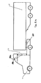
- an adjustable wind deflector 10 is shown on the roof 4 of a towing vehicle 1.
- a third position sensor S3, the inclination of the wind deflector 10 is detected.
- the third position sensor S3 and the third motor drive device 13 are also connected to the control device.
- FIG. 8 a block diagram of the controller is shown.
- the control device 40 which has a display device 41, the position sensors S1, S2 and S3 and the corresponding drive means 23, 33 and 13 are connected.
- the control unit is preferably placed in the driver's cab, so that the driver can also read all the information on the display device 41 while driving and if necessary can also make a shift of the fifth wheel and / or the wind deflector system via the control device 40.
- the controller may have appropriate control circuits, so that an adjustment of the drive means 13, 23 and 33 can be done automatically, depending on which driving situation is given.
- FIG. 9 an exemplary characteristic diagram is shown, in which the speed V against the lifting height H for different gap widths b 1 , b 2 , b 3 (widths of the gap 3) are plotted.
- a lifting height H 1 is set by the control device 40 on the adjusting device 20 for the gap width b 1 .
- the driver or the controller can automatically to another characteristic, eg. For example, change for b 2 , with the result that the adjustment is moved both in the horizontal direction and in the vertical direction.
- an adaptation takes place along the characteristic curve b 2 .
Abstract
Description
- Die Erfindung betrifft eine Verstellvorrichtung für eine Sattelkupplung gemäß dem Oberbegriff des Patentanspruchs 1. Die Erfindung bezieht sich auch auf ein Windabweisersystem, das am Fahrerhaus einer Sattelzugmaschine angeordnet ist, sowie auf ein Steuergerät für ein Zugfahrzeug mit einer Sattelkupplung. Weiterhin ist die Erfindung auf eine Vorrichtung zur Verringerung des Luftwiderstandes eines Sattelzugs gerichtet.
- Verschiebevorrichtungen sind beispielsweise aus der
DE-AS 17 80 488 EP 0 503 954 A1 oder derDE 199 44 684 C1 bekannt. - Ferner ist aus der
WO 02/070328 A1 - Außer einer horizontalen Verschiebung der Sattelkupplung ist es auch möglich, ein Anheben und Absenken der Sattelkupplung durchzuführen, da die Auflieger unterschiedliche Höhen aufweisen können, so dass eine entsprechende Anpassung vorzunehmen ist. Für diese Zwecke gibt es Hubvorrichtungen, die beispielsweise in der
DE 198 929 A1 oderDE 198 39 357 A1 beschrieben werden. - Da die Sattelkupplung sehr große Kräfte nicht nur in vertikaler Richtung, sondern auch große Kräfte in Fahrtrichtung sowie große Seitenkräfte aufnehmen muss, ist eine hohe Stabilität der Hubvorrichtung in Bezug auf den Fahrzeugrahmen in allen Richtungen erforderlich, und zwar sowohl im abgesenkten als auch im angehobenen Zustand. Die Hubvorrichtung gemäß der
DE 198 39 357 A1 besitzt daher eine Grundplatte, an der Hebelarme um eine horizontale Achse schwenkbar gelagert sind. Am anderen Ende der Hebelarme sind die Sattelkupplung sowie die Ausstellarme befestigt. Zwischen den Ausstellarmen und den Hebelarmen sind Druckmittelzylinder angeordnet, um die Hubvorrichtung anzuheben bzw. abzusenken. Diese Hubvorrichtung ist zwar fernbedienbar, jedoch muss der Fahrer die jeweilige Hubhöhe an Ort und Stelle überprüfen. - Die bisher bekannten Verschiebe- und Hubeinrichtungen sind dafür ausgelegt, vor Beginn der Fahrt eine Anpassung an die Auslegung von Zugfahrzeug und Auflieger vorzunehmen. Es hat sich jedoch gezeigt, dass der Spalt oder Zwischenraum, der zwischen der Aufliegerfront und dem Fahrerhaus der Zugmaschine entsteht, während der Fahrt zu aerodynamischen Verwirbelungen führt, die den Luftwiderstand und somit den Kraftstoffverbrauch des Sattelzuges beeinflussen.
- Um diesem Effekt entgegenzuwirken, werden häufig Windabweiser verwendet, um die Luft gezielt über den Spalt zu leiten. Diese sind schwer, teuer und fest installiert. Ein Umbau muss manuell durchgeführt wird, was ist in der Regel nur vom Zwischenraum aus möglich ist.
- Es ist grundsätzlich sinnvoll, diesen Spalt oder Zwischenraum so klein wie möglich zu gestalten. Andererseits könnte ein zu kleiner Spalt wiederum dazu führen, dass bei Kurvenfahrt die Ecken des Sattelanhängers gegen die Rückwand des Fahrerhauses schlagen.
- Auch kann es Situationen geben, bei denen es sinnvoll ist, einen großen Spalt zuzulassen, um beispielsweise Platz für Aggregate zu schaffen oder im Stand die Zugänglichkeit zu den Versorgungsleitungen für den Sattelanhänger zu verbessern.
- Mit den bekannten Verschiebeeinrichtungen ist zwar ein Verschieben des Aufliegers möglich, der Fahrer muss jedoch die Mechanik der Verschiebeeinrichtung öffnen, dann das Spaltmaß durch Verfahren der Zugmaschine verändern, die Mechanik wieder verriegeln und sich von deren ordnungsgemäßen Verriegelungszustand überzeugen. Dieser Vorgang erfordert einiges an Übung und kann zu erheblicher körperlicher Belastung bei den Fahrern führen. Zudem ist dies immer nur möglich, während das Fahrzeug steht, nicht aber während der Fahrt.
- Es ist daher Aufgabe der Erfindung, eine Vorrichtung sowie ein Steuergerät bereitzustellen, mit denen es möglich ist, auch während der Fahrt die Position des Aufliegers relativ zum Zugfahrzeug zu verändern, insbesondere den Luftwiderstand des Sattelzugs bei hohen Geschwindigkeiten zu reduzieren.
- Die Aufgabe wird gemäß einer ersten Alternative mit einer Verstellvorrichtung gelöst, bei der die Betätigungseinrichtung zum Verschieben des Schlittens eine erste motorische Antriebseinrichtung umfasst, und bei der mindestens ein erster Positionssensor zur Erkennung der Schlittenposition vorgesehen ist, wobei mindestens der erste Positionssensor an eine Steuereinrichtung angeschlossen ist.
- Aufgrund der Beibehaltung des Formschlusses wird die Mechanik der Verschiebeeinrichtung nicht geöffnet, so dass der Schlitten auch während des Verschiebens zu jeder Zeit gesichert ist. Der Auflieger kann somit gegenüber dem Zugfahrzeug nicht unkontrolliert verschieben und Schaden anrichten.
- Durch die motorische Antriebseinrichtung wird es erstmals möglich, die Position der Sattelkupplung auch während der Fahrt zu verändern. Das Spaltmaß, also die Größe des Zwischenraums zwischen dem Fahrerhaus und dem Auflieger, ist in Abhängigkeit der Fahrsituation individuell anpassbar, so dass der Abstand bei langsamer Fahrt, z.B. beim Rangierbetrieb, oder im Stand groß und bei schneller Autobahnfahrt klein ist. Die Verwirbelungen im Zwischenraum zwischen Fahrerhaus und Aufliegerfront lassen sich insbesondere bei schneller Fahrt reduzieren, so dass der Luftwiderstand des Sattelzuges insgesamt verringert wird.
- Durch den oder die Positionssensoren wird dem Fahrer insbesondere während der Fahrt mitgeteilt, wo sich die Sattelkupplung befindet und wie weit die Verschiebeeinrichtung und somit die Sattelkupplung verschoben werden kann, wobei das Verschieben der Sattelkupplung durch Steuersignale des Fahrers möglich ist oder auch automatisch erfolgen kann. Im letzten Fall können hierfür vorgegebene Werte in der Steuereinrichtung für die jeweilige Fahrsituation abgelegt sein.
- Die Steuereinrichtung ist daher vorzugsweise ebenfalls elektrisch mit der ersten Antriebseinrichtung verbunden.
- Die Steuereinrichtung umfasst vorzugsweise eine Anzeigeeinrichtung, die als optische und/oder akustische Anzeige ausgebildet sein kann und vorzugsweise im Fahrerhaus platziert ist. Die Anzeigeeinrichtung kann permanent aktiv sein, d.h. die Position der Sattelkupplung wird dauerhaft angezeigt. Es kann auch eine Kopplung mit der Fahrzeugzündung vorgesehen sein, so dass beim Einschalten der Zündung die aktuelle Stellung der Sattelkupplung bzw. des Schlittens angezeigt wird.
- Antriebseinrichtungen, die den erforderlichen Formschluss gewährleisten, sind vorzugsweise solche, die über mindestens eine Antriebsspindel mit Spindelmutter oder über mindestens eine Zahnstange und ein Zahnrad verfügen. Auch Antriebseinrichtungen, die mittels Druckmittelzylindermotoren arbeiten, erfüllen diese Anforderungen und können als motorische Antriebseinrichtungen eingesetzt werden.
- Im Falle einer Antriebseinrichtung mit Antriebsspindel ist die Spindelmutter vorzugsweise am Schlitten angeordnet.
- Der Ort und die Art des Positionssensors hängen von der jeweiligen baulichen Ausgestaltung der Verstellvorrichtung ab.
- Der erste Positionssensor kann beispielsweise ein Abstandssensor sein. Der erste Positionssensor kann auch ein Drehwinkelmesser sein, wenn z. Bsp. ein Antriebsmotor mit Antriebsspindel verwendet wird.
- Es ist auch möglich, mindestens zwei erste Positionssensoren an einer Führungsschiene anzuordnen. Vorzugsweise sind die ersten Positionssensoren in diesem Fall induktive Sensoren.
- Eine unterschiedliche Bauhöhe von Fahrerhaus und Auflieger beeinträchtigt ebenfalls den Luftwiderstand des Sattelzugs. Es ist deshalb vorteilhaft, wenn die Sattelkupplung nicht nur horizontal verschiebbar ist, sondern auch abgesenkt bzw. angehoben werden kann. Der Auflieger kann je nach Bauweise während der Fahrt so weit abgesenkt werden, dass er hinter dem Fahrerhaus verschwindet, so dass der Luftwiderstand im Wesentlichen durch das Zugfahrzeug bestimmt wird.
- Hierzu weist die Verstellvorrichtung außer einer Verschiebeeinrichtung vorzugsweise auch eine Hubeinrichtung auf.
- Die Hubeinrichtung ist vorzugsweise auf dem Schlitten der Verschiebeeinrichtung angeordnet. Die Sattelkupplung ist in diesem Fall an der Hubeinrichtung befestigt.
- Es ist auch möglich, die Hubeinrichtung auf dem Zugfahrzeug zu positionieren und auf der Hubeinrichtung die Verschiebeeinrichtung anzuordnen. In diesem Fall sind die Führungsschienen der Verschiebeeinrichtung auf der Hubeinrichtung angeordnet und die Sattelkupplung ist auf der Verschiebeeinrichtung befestigt.
- Auch die Hubeinrichtung weist vorzugsweise eine eigene zweite motorische Antriebseinrichtung auf, die ebenfalls die Beibehaltung des Formschlusses beim Anheben und Absenken gewährleistet.
- Damit auch die Hubeinrichtung vom Fahrer oder automatisch betätigt werden kann, ist die zweite Antriebseinrichtung ebenfalls an die Steuereinrichtung angeschlossen.
- Auch die Hubeinrichtung verfügt über mindestens einen zweiten Positionssensor, der die Hubhöhe detektiert und der an die Steuereinrichtung angeschlossen ist.
- Vorzugsweise umfasst die Steuereinrichtung eine Kontrolleinrichtung, die vorzugsweise die Funktionsfähigkeit des oder der Positionssensoren und gegebenenfalls weiterer elektronischer Bauteile überprüft.
- Nicht in allen Fällen lässt sich der Auflieger aufgrund seiner Bauhöhe hinter dem Fahrerhaus versenken, so dass es vorteilhaft ist, mindestens einen Windabweiser auf dem Dach des Fahrerhauses einzubeziehen. Derartige Windabweiser sind bereits bekannt und besitzen meist eine gekrümmte Abweiserplatte.
- Das erfindungsgemäße Windabweisersystem mit mindestens einem Windabweiser für das Dach eines Führerhauses eines Zugfahrzeugs eines Sattelzuges ist dadurch gekennzeichnet, dass der Windabweiser schwenkbar auf dem Dach angeordnet ist und eine dritte motorische Antriebseinrichtung aufweist und dass mindestens ein dritter Positionssensor vorgesehen ist, der den Einstellwinkel des Windabweisers detektiert und der an eine Steuereinrichtung angeschlossen ist.
- Es ist vorteilhaft, wenn die dritte Antriebseinrichtung ebenfalls an die Steuereinrichtung angeschlossen ist, damit auch der Windabweiser fernbedienbar ist und entweder vom Fahrer über Steuerbefehle eingestellt werden kann oder automatisch unter Berücksichtigung der Positionssignale des oder der Positionssensoren verschwenkt werden kann.
- Der Windabweiser auf dem Dach des Fahrerhauses ist um eine horizontale Achse schwenkbar. Das Windabweisersystem kann auch seitlich am Fahrerhaus angeordnete Windabweiser aufweisen, die um eine vertikale Achse schwenkbar sind. Auch diese seitlichen Windabweiser können eine vierte Antriebseinrichtung und mindestens einen vierten Positionssensor aufweisen, der an die Steuereinrichtung angeschlossen ist.
- Die Steuereinrichtung des Windabweisersystems kann eine separate Steuereinrichtung sein. Es ist aber auch möglich, den oder die dritten und/oder vierten Positionssensor/en und/oder die dritte und/oder vierte Antriebseinrichtung an die Steuereinrichtung der Verstellvorrichtung anzuschließen.
- Das erfindungsgemäße Steuergerät für ein Zugfahrzeug mit Sattelkupplung sieht eine Steuereinrichtung sowie mindestens einen Positionssensor vor, der an einer Verschiebeeinrichtung und/oder einer Hubeinrichtung der Sattelkupplung und/oder an einem verschwenkbaren Windabweisersystem am Führerhaus des Zugfahrzeugs angeordnet ist, wobei die Steuereinrichtung mit mindestens einem Positionssensor und mit einer Antriebseinrichtung der Verschiebeeinrichtung und/oder der Hubeinrichtung der Sattelkupplung und/oder des Windabweisersystems elektrisch verbunden ist.
- Die Steuereinrichtung umfasst vorzugsweise auch eine Kontrolleinrichtung, die vorzugsweise die Funktionsfähigkeit des oder der Sensoren und gegebenenfalls weiterer elektronischer Bauteile überprüft. Dadurch wird die Sicherheit hinsichtlich der Verstellung des Windabweisers und/oder der Sattelkupplung erhöht. Die Kontrolleinrichtung kann beispielsweise auch derart ausgestattet sein, dass ein Verstellen von Windabweiser, Verschiebeeinrichtung und/oder Hubeinrichtung nur dann möglich ist, wenn die Funktionsfähigkeit mindestens sämtlicher Positionssensoren gewährleistet ist.
- Das Steuergerät ist weiterhin dadurch gekennzeichnet, dass es eine Anzeigeeinrichtung umfasst, die die horizontale und/oder vertikale Position der Sattelkupplung und/oder die Neigung des Windabweisersystems anzeigt. Diese Anzeigeeinrichtung ist vorzugsweise im Fahrerhaus angeordnet, damit der Fahrer über die jeweilige Position der einzelnen Komponenten informiert ist.
- Die Steuereinrichtung kann zusätzlich an die verstellbare Federeinrichtung des Aufliegers angeschlossen sein, so dass dann, wenn eine Höhenverstellung an der Sattelkupplung vorgenommen wird auch im Bereich des Fahrgestells eine Höhenanpassung vorgenommen werden kann.
- Die Steuereinrichtung ist vorzugsweise zur Auswertung der Positionssignale der Positionssensoren ausgebildet, wobei nach Vergleich mit Sollwerten Steuersignale an die Antriebseinrichtungen abgegeben werden. Es wird dadurch ein automatischer Betrieb möglich, in den der Fahrer nicht eingreifen muss. Die Sollwerte können beispielsweise an die Fahrgeschwindigkeit geknüpft sein, so dass bei schneller Fahrt auf der Autobahn aufgrund eines Sollwertes für den Spaltabstand die Sattelkupplung mittels der Verstelleinrichtung derart nach vorne verschoben wird, dass der Spalt minimiert wird. Auch kann über die Steuereinrichtung automatisch die Neigung des Windabweisers optimiert und - wenn es die Bauweise zulässt - auch der Auflieger über die Hubeinrichtung entsprechend abgesenkt werden.
- Die Steuereinrichtung kann gemäß einer weiteren Ausführungsform auch einen Regelkreis aufweisen. Anhand von Kennlinien wird z. Bsp. je nach Fahrbedingungen die Verstellvorrichtung nachgeführt.
- Die erfindungsgemäße Vorrichtung gemäß einer zweiten Alternative ist eine Vorrichtung zur Verringerung des Luftwiderstandes eines Sattelzuges aus Zugfahrzeug und Auflieger, die eine Verschiebeeinrichtung zum Verschieben der Sattelkupplung in Längsrichtung des Zugfahrzeuges und/oder eine Hubeinrichtung zum Anheben oder Absenken der Sattelkupplung und/oder ein schwenkbar am Fahrerhaus angeordnete Windabweisersystem vorsieht, wobei die Verschiebeeinrichtung und/oder die Hubeinrichtung und/oder das Windabweisersystem über motorische Antriebe und Positionssensoren verfügen, wobei die Antriebseinrichtungen und die Positionssensoren an eine gemeinsame Steuereinrichtung angeschlossen sind.
- Beispielhafte Ausführungsformen der Erfindung werden nachfolgend anhand der Zeichnungen näher erläutert.
-
- Figuren 1, 2a, 2b und 3
- Seitenansichten eines Sattelzuges mit unterschiedlichen Aufliegerpositionen,
- Figur 4
- eine Seitenansicht einer Verschiebeeinrichtung,
- Figur 5
- eine perspektivische Draufsicht auf eine Verschiebeeinrichtung,
- Figur 6
- eine Seitenansicht einer Verstelleinrichtung mit Verschiebeeinrichtung und Hubeinrichtung,
- Figur 7
- die Seitenansicht eines Windabweisers und
- Figur 8
- ein Block-Schaltbild eines Steuergerätes und
- Figur 9
- ein beispielhaftes Kennliniendiagramm.
- In den
Figuren 1 bis 3 ist jeweils ein Sattelzug bestehend aus einem Zugfahrzeug 1 und einem Auflieger 2 in verschiedenen Positionen dargestellt. Das Zugfahrzeug 1 besitzt eine Verstellvorrichtung 20 mit einer darauf angeordneten Sattelkupplung, in die der Auflieger 2 mit seinem Königszapfen eingreift. In denFiguren 1 bis 3 ist die Sattelkupplung nicht, und die Verstellvorrichtung nur schematisch dargestellt. Ferner besitzt das Zugfahrzeug 1 auf seinem Dach 4 einen verschwenkbaren Windabweiser 10a sowie seitliche Windabweiser 10b am Fahrerhaus. - In der
Figur 1 befindet sich der Auflieger 2' in angehobener Position. Der Windabweiser 10a' befindet sich in hochgeschwenkter Position. Um den Luftwiderstand zu verringern, kann der Auflieger in die Position 2 abgesenkt werden, indem die Verstellvorrichtung 20 sowie das Fahrgestell des Aufliegers abgesenkt werden. Das Absenken des Fahrgestells erfolgt vorzugsweise über die verstellbare Federung, insbesondere die Luftfederung des Aufliegers, die zu diesem Zweck an die Steuereinrichtung der Verstellvorrichtung 20 angeschlossen ist. - In der
Figur 2a befindet sich der Auflieger 2 in einer abgesenkten Position, so dass die Oberkante des Aufliegers auf gleicher Höhe liegt wie der Scheitel des Windabweisers 10a, der sich ebenfalls in abgesenkter Position befindet. In dieser Anordnung ist der Zwischenraum 3 zwischen dem Fahrerhaus 1 und der Vorderfront des Aufliegers 2 relativ groß, so dass es in diesem Zwischenraum bei schneller Autobahnfahrt zu Verwirbelungen kommt, die das Fahrzeug bremsen. Um hier Abhilfe zu schaffen, ist es möglich, mittels der Verstellvorrichtung 20 die Sattelkupplung nach links zu verschieben, so dass der Zwischenraum 3 entsprechend kleiner wird, wie dies in derFigur 2b dargestellt ist. - In der
Figur 3 ist eine angehobene Position des Aufliegers 2/2' mit kleinem und großem Zwischenraum 3 dargestellt. Diese angehobene Position ist bei unebenem Gelände oder für extreme Rangiermanöver zweckmäßig. - Alle gezeigten Positionsänderungen können während der Fahrt durchgeführt werden.
- In der
Figur 4 ist die Seitenansicht einer Verschiebeeinrichtung 21 schematisch dargestellt. Auf einem Rahmen 25, der auf dem Zugfahrzeug montiert ist, ist ein Schlitten 26 verschiebbar angeordnet. Hierzu sind an einem Rahmen 25 Führungsschienen 27 angeordnet, wie dies in derFigur 5 dargestellt ist. Am Schlitten 26 sind Lagerböcke 6 zur Aufnahme der Sattelkupplung 5 befestigt. - Dieser Schlitten 26 wird von einer Antriebsspindel 24 und einem motorischen Antrieb 23a oder 23b angetrieben, wobei die Antriebsspindel 24 an einer Spindelmutter 22 am Schlitten 26 angreift, die in
Figur 5 verdeckt ist. Der motorische Antrieb 23a kann somit auf dem Schlitten 26 oder aber als motorischer Antrieb 23b auf einer Traverse 28 des Rahmens 25 angeordnet sein, wie dies inFigur 5 gezeigt ist. Die Antriebsspindel 24 ist auf einer Traverse 29 des Rahmens 25 drehbar gelagert. Während des Verstellens des Schlittens 26 bleibt der Formschluss zwischen Spindelmutter 22 und Antriebsspindel 24 erhalten, so dass auch ein Verstellen während der Fahrt möglich ist. - Am Schlitten 26 ist ferner ein erster Positionssensor S1 angebracht, der beispielsweise als induktiver Sensor mit entsprechenden Gegenstücken beispielsweise an der Führungsschiene 27 zusammenwirkt und auf diese Weise die Position des Schlittens 26 auf dem Rahmen 25 bzw. bezüglich der Führungsschiene 27 detektiert. Dieser erste Positionssensor S1 ist an eine in
Figur 4 und5 nicht dargestellte Steuereinrichtung angeschlossen. Dies gilt auch für die motorische Antriebseinrichtung 23a bzw. 23b, die ebenfalls an die Steuereinrichtung elektrisch angeschlossen ist. - In der
Figur 6 ist eine weitere Ausführungsform dargestellt, bei der auf der Verschiebeeinrichtung 21 eine Hubeinrichtung 30 angeordnet ist, die ein Paar Hebelarme 31 und entsprechend ein Paar Ausstellarme 32 aufweist, wobei im gemeinsamen Gelenkpunkt von Ausstellarm und Hebelarm die Sattelkupplung 5 in einem entsprechenden Lagerbock 6 befestigt ist. Zum Aufrichten und Absenken der Hubeinrichtung 30 ist eine zweite motorische Antriebseinrichtung 33 in Form eines Druckmittelzylinders vorgesehen. Auch dieser Druckmittelzylinder erfüllt die Formschlussbedingung beim Anheben und Absenken der Sattelkupplung. - Die Hubeinrichtung 30 verfügt über einen zweiten Positionssensor S2, der die Hubhöhe beispielsweise anhand des Schwenkwinkels des Ausstellarms 32 detektiert. Die motorische Antriebseinrichtung 33 ist ebenso wie der Positionssensor S2 an die in der
Figur 6 nicht dargestellte Steuereinrichtung angeschlossen. - In der
Figur 7 ist ein verstellbarer Windabweiser 10 auf dem Dach 4 eines Zugfahrzeugs 1 dargestellt. Die Verstellung des Windabweisers 10 erfolgt über eine dritte motorische Antriebseinheit in Form eines Druckmittelzylinders 13. Über einen dritten Positionssensor S3 wird die Neigung des Windabweisers 10 detektiert. Auch der dritte Positionssensor S3 und die dritte motorische Antriebseinrichtung 13 sind an die Steuereinrichtung angeschlossen. - In der
Figur 8 ist ein Block-Schaltbild des Steuergerätes dargestellt. An die Steuereinrichtung 40, die eine Anzeigeeinrichtung 41 aufweist, sind die Positionssensoren S1, S2 und S3 sowie die entsprechenden Antriebseinrichtung 23, 33 und 13 angeschlossen. In einer Erweiterung können auch die seitlichen Windabweiser mit ihrem Antriebseinrichtungen und Positionssensoren S4 sowie die Federeinrichtung des Aufliegers einbezogen sein. Das Steuergerät ist vorzugsweise im Fahrerhaus platziert, so dass der Fahrer auch während der Fahrt sämtliche Informationen an der Anzeigeeinrichtung 41 ablesen kann und gegebenenfalls über die Steuereinrichtung 40 auch eine Verschiebung der Sattelkupplung und/oder des Windabweisersystems vornehmen kann. Auch kann das Steuergerät über entsprechende Regelkreise verfügen, so dass eine Verstellung der Antriebseinrichtungen 13, 23 und 33 automatisch erfolgen kann, je nachdem, welche Fahrsituation gegeben ist. - In der
Figur 9 ist ein exemplarisches Kennlinien-Diagramm dargestellt, in dem die Geschwindigkeit V gegen die Hubhöhe H für verschiedene Spaltbreiten b1, b2, b3 (Breiten des Zwischenraums 3) aufgetragen sind. Bei einer Geschwindigkeit V1 wird von der Steuereinrichtung 40 an der Verstellvorrichtung 20 für die Spaltbreite b1 eine Hubhöhe H1 eingestellt. Sollte jedoch bei der Geschwindigkeit V1 die Spaltbreite b1 und die Höhe H1 aufgrund der Straßenverhältnisse nicht praktikabel sein, kann der Fahrer oder die Steuereinrichtung automatisch auf eine andere Kennlinie, z. Bsp. für b2 wechseln, mit der Folge, dass die Verstellvorrichtung sowohl in horizontaler Richtung als auch in vertikaler Richtung verfahren wird. Bei Änderung der Geschwindigkeit V erfolgt entlang der Kennlinie b2 jeweils eine Anpassung. -
- 1
- Zugfahrzeug
- 2, 2'
- Auflieger
- 3
- Zwischenraum
- 4
- Dach
- 5
- Sattelkupplung
- 6
- Lagerbock
- 10a, 10'a, 10b
- Windabweiser
- 13
- dritte Antriebseinrichtung
- 20
- Verstelleinrichtung
- 21
- Verschiebeeinrichtung
- 22
- Spindelmutter
- 23a,b
- erste Antriebseinrichtung
- 24
- Antriebsspindel
- 25
- Rahmen
- 26
- Schlitten
- 27
- Führungsschiene
- 28
- Traverse
- 29
- Traverse
- 30
- Hubeinrichtung
- 31
- Hebelarm
- 32
- Ausstellarm
- 33
- zweite Antriebseinrichtung
- 40
- Steuereinrichtung
- 41
- Anzeigeeinrichtung
- S1
- erster Positionssensor
- S2
- zweiter Positionssensor
- S3
- dritter Positionssensor
- S4
- vierter Positionssensor
Claims (13)
- Vorrichtung zur Verringerung des Luftwiderstandes eines Sattelzugs aus Zugfahrzeug (1) und Auflieger (2)
mit einer Verschiebeeinrichtung (21) zum Verschieben der Sattelkupplung (5) in Längsrichtung des Zugfahrzeugs (1) und/oder einer Hubeinrichtung (30) zum Anheben oder Absenken der Sattelkupplung (5),
mit mindestens einem schwenkbar am Fahrerhaus des Zugfahrzeugs (1) angeordneten Windabweiser (10a, 10b),
wobei die Verschiebeeinrichtung (21) und/oder die Hubeinrichtung (30) und/oder der Windabweiser (10a, 10b) über motorische Antriebseinrichtungen (13, 23a, 23b, 33) und Positionssensoren (S1, S2, S3, S4) verfügen, wobei die Antriebseinrichtungen (13, 23a, 23b, 33) und die Positionssensoren (S1, S2, S3, S4) an eine gemeinsame Steuereinrichtung (40) angeschlossen sind. - Vorrichtung nach Anspruch 1, dadurch gekennzeichnet, dass die Steuereinrichtung (40) eine Kontrolleinrichtung umfasst, welche die Funktionsfähigkeit mindestens des oder der Positionssensoren (S1, S2, S3, S4) überprüft.
- Vorrichtung nach Anspruch 1 oder 2, dadurch gekennzeichnet, dass diese zusammen mit der Steuereinrichtung (40) ein Steuergerät bildet, welches eine Anzeigeeinrichtung (41) umfasst, welche die horizontale und/oder vertikale Position der Sattelkupplung (5) und/oder die Neigung des
Windabweisers (10a, 10b) anzeigt. - Vorrichtung nach einem der Ansprüche 1 bis 3, dadurch gekennzeichnet, dass die Steuereinrichtung (40) mit einer verstellbaren Federung des Aufliegers (2) verbunden ist.
- Vorrichtung nach einem der Ansprüche 1 bis 4, dadurch gekennzeichnet, dass die Steuereinrichtung (40) zur Auswertung der Positionssignale der Positionssensoren (S1, S2, S3, S4) ausgebildet ist und nach Vergleich mit Sollwerten Steuersignale an die Antriebseinrichtungen (13, 23a, 23b, 33) abgibt.
- Vorrichtung nach einem der Ansprüche 1 bis 5, dadurch gekennzeichnet, dass die Steuereinrichtung (40) einen Regelkreis aufweist.
- Vorrichtung nach einem der Ansprüche 1 bis 6, dadurch
gekennzeichnet, dass die Verschiebeeinrichtung (21) zwei auf dem Zugfahrzeug (1), in dessen Längsrichtung angeordnete Führungsschienen (27) und einen auf den
Führungsschienen (27) verschiebbaren Schlitten (26) mit einer Betätigungseinrichtung zum Verschieben des Schlittens (26) aufweist, wobei die Betätigungseinrichtung ein Verschieben unter Beibehaltung des Formschlusses zwischen einem Rahmen (25) und dem Schlitten (26) ermöglicht und zum Verschieben des Schlittens die erste motorische
Antriebseinrichtung (23a, 23b) umfasst, - Vorrichtung nach Anspruch 7, dadurch gekennzeichnet, dass der erste Positionssensor (S1) ein Abstandssensor oder ein Drehwinkelmesser ist.
- Vorrichtung nach Anspruch 7 oder 8, dadurch gekennzeichnet, dass der erste Positionssensor (S1) ein induktiver Sensor ist.
- Vorrichtung nach einem der Ansprüche 7 bis 9, dadurch gekennzeichnet, dass die Hubeinrichtung (30) auf dem Schlitten (26) die eigene, zweite motorische
Antriebseinrichtung (33) aufweist. - Vorrichtung nach Anspruch 10, dadurch gekennzeichnet, dass der zweite Positionssensor (S2) an der Hubeinrichtung (30) angeordnet ist und die Hubhöhe detektiert.
- Vorrichtung nach einem der Ansprüche 1 bis 11, dadurch gekennzeichnet, dass der Windabweiser (10a) zusammen mit der dritten motorischen Antriebseinrichtung (13) und dem mindestens dritten Positionssensor (S3) ein Windabweisersystem bildet, wobei der dritte
Positionssensor (S3) den Anstellwinkel des Windabweisers (10a) detektiert. - Vorrichtung nach Anspruch 12, dadurch gekennzeichnet, dass das Windabweisersystem den seitlich am Fahrerhaus angeordneten Windabweiser (10b) mit der vierten Antriebseinrichtung und dem vierten Positionssensor (S4) umfasst.
Priority Applications (1)
| Application Number | Priority Date | Filing Date | Title |
|---|---|---|---|
| PL09161464T PL2088062T3 (pl) | 2004-09-18 | 2005-09-03 | Urządzenie regulacyjne, układ zmniejszania oporu powietrza, urządzenie sterujące oraz urządzenie do zmniejszania oporu powietrza zespołu ciągnika siodłowego |
Applications Claiming Priority (2)
| Application Number | Priority Date | Filing Date | Title |
|---|---|---|---|
| DE102004045662A DE102004045662B4 (de) | 2004-09-18 | 2004-09-18 | Verstellvorrichtung, Steuergerät und Vorrichtung zur Verringerung des Luftwiderstandes eines Sattelzuges |
| EP05784886A EP1812278B1 (de) | 2004-09-18 | 2005-09-03 | Verstellvorrichtung zur verringerung des luftwiderstandes eines sattelzuges |
Related Parent Applications (3)
| Application Number | Title | Priority Date | Filing Date |
|---|---|---|---|
| EP05784886 Previously-Filed-Application | 2005-09-03 | ||
| EP05784886A Division EP1812278B1 (de) | 2004-09-18 | 2005-09-03 | Verstellvorrichtung zur verringerung des luftwiderstandes eines sattelzuges |
| EP05784886.3 Division | 2005-09-03 |
Publications (3)
| Publication Number | Publication Date |
|---|---|
| EP2088062A2 true EP2088062A2 (de) | 2009-08-12 |
| EP2088062A3 EP2088062A3 (de) | 2009-08-19 |
| EP2088062B1 EP2088062B1 (de) | 2011-03-30 |
Family
ID=35170087
Family Applications (2)
| Application Number | Title | Priority Date | Filing Date |
|---|---|---|---|
| EP09161464A Active EP2088062B1 (de) | 2004-09-18 | 2005-09-03 | Verstellvorrichtung, Windabweisersystem, Steuergerät und Vorrichtung zur Verringerung des Luftwiderstandes eines Sattelzuges |
| EP05784886A Active EP1812278B1 (de) | 2004-09-18 | 2005-09-03 | Verstellvorrichtung zur verringerung des luftwiderstandes eines sattelzuges |
Family Applications After (1)
| Application Number | Title | Priority Date | Filing Date |
|---|---|---|---|
| EP05784886A Active EP1812278B1 (de) | 2004-09-18 | 2005-09-03 | Verstellvorrichtung zur verringerung des luftwiderstandes eines sattelzuges |
Country Status (10)
| Country | Link |
|---|---|
| US (3) | US7789412B2 (de) |
| EP (2) | EP2088062B1 (de) |
| CN (2) | CN101691126B (de) |
| AT (2) | ATE447520T1 (de) |
| CA (3) | CA2746654C (de) |
| DE (3) | DE102004045662B4 (de) |
| ES (2) | ES2363865T3 (de) |
| PL (2) | PL1812278T3 (de) |
| RU (1) | RU2379210C2 (de) |
| WO (1) | WO2006029732A1 (de) |
Families Citing this family (82)
| Publication number | Priority date | Publication date | Assignee | Title |
|---|---|---|---|---|
| DE102004045663B4 (de) * | 2004-09-18 | 2008-08-28 | Jost-Werke Gmbh | Verschiebevorrichtung für eine Sattelkupplung |
| SE530237C2 (sv) * | 2005-10-27 | 2008-04-08 | Volvo Lastvagnar Ab | Vändskivearrangemang för hopkoppling av en släpvagn med en dragbil och förfarande för manövrering av nämnda arrangemang |
| SE0502459L (sv) * | 2005-11-07 | 2007-04-17 | Volvo Lastvagnar Ab | Ett dragdon avsedd för tillkoppling av en påhängsvagn |
| US7618086B2 (en) | 2005-12-01 | 2009-11-17 | Thomas Scott Breidenbach | Aerodynamic drag reducing apparatus |
| DE102005060124B4 (de) | 2005-12-16 | 2011-05-05 | Jost-Werke Gmbh | Verschiebevorrichtung für eine auf einem Zugfahrzeug angeordnete Sattelkupplung |
| GB2435246A (en) * | 2006-02-17 | 2007-08-22 | Decoma U K Ltd | Spoiler |
| DE102006012800B4 (de) * | 2006-03-15 | 2008-06-05 | Jost-Werke Gmbh | Steckerkonsole |
| DE102006058561B4 (de) * | 2006-12-12 | 2010-08-26 | Hs Genion Gmbh | Funktionseinrichtung mit schwenkbarem Element |
| DE102006059724B4 (de) * | 2006-12-18 | 2011-03-17 | Hs Genion Gmbh | Luftleitvorrichtung für ein Fahrzeug |
| EP2155537B1 (de) * | 2007-05-14 | 2011-08-10 | Volvo Lastvagnar AB | Traktorführerhaus mit mindestens einer Verkleidung mit einem Luftabweiser. |
| US8360509B2 (en) | 2007-05-17 | 2013-01-29 | Advanced Transit Dynamics, Inc. | Rear-mounted aerodynamic structure for truck cargo bodies |
| US8100461B2 (en) | 2007-05-17 | 2012-01-24 | Advanced Transit Dynamics, Inc. | Rear-mounted aerodynamic structure for truck cargo bodies |
| GB0709876D0 (en) * | 2007-05-23 | 2007-07-04 | Thomson Jim | 5th wheel setting guide for tractor-trailer combination |
| CA2625418A1 (en) * | 2007-11-20 | 2009-05-20 | Colibert Enterprises, Inc. | Displaceable fifth-wheel hitch assembly |
| US7887120B2 (en) * | 2008-01-29 | 2011-02-15 | Transtex Composite Inc. | Aerodynamic trailer skirts |
| US9616943B2 (en) | 2008-01-30 | 2017-04-11 | Volvo Group North America, Llc | Tractor trailer gap control system |
| DE102008056357A1 (de) * | 2008-11-07 | 2010-05-12 | Man Nutzfahrzeuge Ag | Luftleitblech eines Nutzfahrzeugs |
| SE533257C2 (sv) | 2008-12-02 | 2010-08-03 | Scania Cv Ab | Förfarande och system för reglering av förskjutningsläget hos en vändskiva |
| DE102008062150A1 (de) * | 2008-12-16 | 2010-06-24 | Dr. Ing. H.C. F. Porsche Aktiengesellschaft | Verstell-Vorrichtung |
| DE102008064262A1 (de) * | 2008-12-20 | 2010-06-17 | Daimler Ag | Sattelzug |
| DE102009002334B4 (de) | 2009-04-09 | 2012-09-27 | Jost-Werke Gmbh | Steuerungssystem mit einer Verschiebeeinrichtung für eine auf einem Zugfahrzeug angeordnete Sattelkupplung |
| DE102009002335B3 (de) * | 2009-04-09 | 2010-08-19 | Jost-Werke Gmbh | Verfahren und Steuerungssystem für eine Verschiebeeinrichtung mit Abstandsmessung zum Erfassen von Hindernissen |
| US8275521B2 (en) * | 2009-07-17 | 2012-09-25 | International Truck Intellectual Property Company, Llc | System and method for controlling air gap between a tractor and a trailer |
| US7971918B2 (en) | 2009-07-27 | 2011-07-05 | Navistar Canada, Inc. | Extendable sleeper and method of operation |
| US8403401B2 (en) * | 2009-08-24 | 2013-03-26 | Daimler Trucks North America Llc | Adjustable air-deflecting panel for a vehicle |
| US8348297B2 (en) | 2009-09-22 | 2013-01-08 | International Truck Intellectual Property Company, Llc | Slidably adjustable fifth wheel hitch assembly for a vehicle and control system for the same |
| DE102009054570A1 (de) * | 2009-12-11 | 2011-06-16 | Jost-Werke Gmbh | Luftleitsystem |
| WO2011075009A1 (en) * | 2009-12-15 | 2011-06-23 | Volvo Lastvagnar Ab | Arrangement and method for optimizing the position of at least one air deflector |
| US20110210529A1 (en) * | 2010-02-26 | 2011-09-01 | Daimler Trucks North America LLC. | Method and apparatus for adjusting the gap of a fifth wheel of a vehicle |
| US8496285B2 (en) | 2010-04-02 | 2013-07-30 | Daimler Trucks North America Llc | Dynamically adjustable aerodynamic vehicle devices |
| CN101830251B (zh) * | 2010-05-21 | 2011-10-05 | 许朋伟 | 汽车主动减阻装置 |
| WO2012010922A1 (en) * | 2010-07-22 | 2012-01-26 | Renault Trucks | Vehicle having a deformable roof for aerodynamics improvement |
| US8573627B2 (en) * | 2010-11-04 | 2013-11-05 | Saf-Holland, Inc. | Fifth wheel support assembly |
| WO2012090020A1 (en) * | 2010-12-27 | 2012-07-05 | Renault Trucks | Truck and method for controlling such a truck |
| WO2012099568A1 (en) * | 2011-01-17 | 2012-07-26 | Volvo Technology Of America, Inc. | Adjustable towing system and method |
| WO2012099569A1 (en) * | 2011-01-17 | 2012-07-26 | Volvo Group North America, Llc | Tractor trailer gap control system |
| DE102011003791B4 (de) | 2011-02-08 | 2019-05-02 | Jost-Werke Deutschland Gmbh | System zum automatischen Einstellen eines Spaltraumes zwischen einem Motorwagen und einem daran angekuppelten Anhänger |
| US8342556B2 (en) | 2011-04-06 | 2013-01-01 | Navistar Canada, Inc. | Lowrider aerodynamic truck |
| DE102011111456B4 (de) * | 2011-08-30 | 2022-05-05 | Apollo Vredestein B.V. | Luftleiteinrichtung für ein Kraftfahrzeug |
| US20130076064A1 (en) | 2011-09-20 | 2013-03-28 | Advanced Transit Dynamics, Inc. | Rear-mounted retractable aerodynamic structure for cargo bodies |
| EP2771231A4 (de) | 2011-10-27 | 2016-01-06 | Advanced Transit Dynamics Inc | Rückseitig montierte aerodynamische strukturen für frachtkörper |
| US8342558B1 (en) * | 2011-12-27 | 2013-01-01 | Austin Su | Glider hitch for trailer fifth wheel |
| SE536535C2 (sv) * | 2012-06-11 | 2014-02-11 | Scania Cv Ab | Förfarande och system för att förbättra ett lastfordons driftekonomi |
| MX2015000462A (es) | 2012-07-11 | 2015-12-07 | Advanced Transit Dynamics Inc | Estructuras aerodinamicas retractiles para unidades de carga y metodos para controlar la colocación de las mismas. |
| DE102013101017A1 (de) * | 2013-02-01 | 2014-08-07 | Sven Dörnbach | Sattelkupplung |
| DE102014000492A1 (de) * | 2014-01-14 | 2015-07-16 | Wabco Gmbh | Verfahren zur Niveauregelung eines Fahrzeugs |
| US9296433B2 (en) | 2014-01-14 | 2016-03-29 | Vanguard National Trailer Corporation | Trailer sail |
| EP3636519A1 (de) * | 2014-03-21 | 2020-04-15 | Magna International Inc. | Entfaltbares aerodynamisches seitenwandsystem |
| WO2015191918A1 (en) * | 2014-06-12 | 2015-12-17 | Quantum Fuel Systems Technologies Worldwide. Inc. | Aerodynamic and adjustable efficient back of cab fuel tank housing |
| MX2017001690A (es) * | 2014-08-05 | 2017-11-17 | Saf-Holland Inc | Deslizador de reposicionamiento activo de la quinta rueda. |
| US9688319B2 (en) | 2014-10-01 | 2017-06-27 | Traylor Aerodynamic Systems, LLC | Retractable fairing for reducing aerodynamic drag at the rear end of a commerical motor vehicle |
| US9694644B2 (en) * | 2014-10-29 | 2017-07-04 | International Truck Intellectual Property Company, Llc | Active control of trailer pitch |
| WO2016151351A1 (en) | 2015-03-20 | 2016-09-29 | Carrier Corporation | Heat and dust shield |
| EP3069911B1 (de) | 2015-03-20 | 2019-10-09 | Carrier Corporation | Wärmeablenkelement für zugfahrzeug-anhängerkühlsystem |
| CA2940932C (en) | 2015-09-07 | 2022-07-19 | Transtex Composite Inc. | Self-repositioning strut portion for aerodynamic skirt |
| US9862242B2 (en) * | 2015-12-21 | 2018-01-09 | Jason P. Lurie | Coupling system |
| US10384728B2 (en) | 2016-03-28 | 2019-08-20 | Transtex Llc | Beam connector and method of installation thereof |
| KR101925494B1 (ko) | 2016-06-15 | 2018-12-05 | 대우조선해양 주식회사 | 충격 흡수가 용이한 윈드 디플렉터 |
| EP3379222B1 (de) | 2017-03-22 | 2020-12-30 | Methode Electronics Malta Ltd. | Auf magnetoelastik basierte sensoranordnung |
| EA031676B1 (ru) * | 2017-03-23 | 2019-02-28 | Анатолий Эдуардович Юницкий | Высокоскоростной транспортный модуль |
| US11221262B2 (en) | 2018-02-27 | 2022-01-11 | Methode Electronics, Inc. | Towing systems and methods using magnetic field sensing |
| US11491832B2 (en) | 2018-02-27 | 2022-11-08 | Methode Electronics, Inc. | Towing systems and methods using magnetic field sensing |
| US11084342B2 (en) | 2018-02-27 | 2021-08-10 | Methode Electronics, Inc. | Towing systems and methods using magnetic field sensing |
| US11135882B2 (en) | 2018-02-27 | 2021-10-05 | Methode Electronics, Inc. | Towing systems and methods using magnetic field sensing |
| US10670479B2 (en) | 2018-02-27 | 2020-06-02 | Methode Electronics, Inc. | Towing systems and methods using magnetic field sensing |
| US11014417B2 (en) | 2018-02-27 | 2021-05-25 | Methode Electronics, Inc. | Towing systems and methods using magnetic field sensing |
| US11338866B2 (en) * | 2018-05-31 | 2022-05-24 | Uatc, Llc | Movable front shield for vehicles |
| CN109130730B (zh) * | 2018-10-25 | 2020-05-29 | 安徽江淮汽车集团股份有限公司 | 一种液动式轴心位置可调的牵引器总成 |
| CN110116762B (zh) * | 2019-05-16 | 2021-11-16 | 安徽科瑞特模塑有限公司 | 一种智能型自动调节式货车导流罩 |
| WO2021013495A1 (en) * | 2019-07-24 | 2021-01-28 | Volvo Truck Corporation | A fifth wheel release arrangement |
| US11465697B2 (en) | 2019-08-28 | 2022-10-11 | Paccar Inc | Mounting assembly for movable fairing |
| DE102019124263B4 (de) * | 2019-09-10 | 2022-08-18 | Saf-Holland Gmbh | Kupplungssystem |
| DE102019124273B4 (de) * | 2019-09-10 | 2023-09-28 | Saf-Holland Gmbh | Sattelkupplung, Verfahren zur Bestimmung eines Belastungszustands und/oder eines Verschleißzustands einer Sattelkupplung und Verfahren zum Aufrüsten einer Sattelkupplung |
| CN110884583A (zh) * | 2019-11-05 | 2020-03-17 | 一汽解放汽车有限公司 | 一种牵引车鞍座及牵引车 |
| IT201900021075A1 (it) * | 2019-11-13 | 2021-05-13 | Bitron Spa | Sistema per regolare un dispositivo di deflessione aria su un autoveicolo |
| RU200386U1 (ru) * | 2020-03-03 | 2020-10-21 | Публичное акционерное общество "КАМАЗ" | Двухосный седельный тягач |
| CN113212571A (zh) * | 2021-04-21 | 2021-08-06 | 河北科技大学 | 能够驱动半挂车车厢纵移的随动装置以及半挂车 |
| CN113212572A (zh) * | 2021-04-21 | 2021-08-06 | 河北科技大学 | 一种驱动半挂车车厢转弯后移的随动装置以及半挂车 |
| DE102021112453A1 (de) | 2021-05-12 | 2022-11-17 | Man Truck & Bus Se | Autonom fahrendes Zugfahrzeug mit aufklappbarem Luftleitelement |
| CN113815738B (zh) * | 2021-09-30 | 2023-01-03 | 东风商用车有限公司 | 一种牵引车可调节鞍座结构及其控制系统、控制方法 |
| CN114872802B (zh) * | 2022-06-10 | 2023-10-17 | 一汽解放汽车有限公司 | 车辆风阻控制方法、装置和存储介质 |
| CN115042883A (zh) * | 2022-06-13 | 2022-09-13 | 吉林大学 | 一种卡车尾部可调节导流板 |
Citations (6)
| Publication number | Priority date | Publication date | Assignee | Title |
|---|---|---|---|---|
| EP0503954A1 (de) | 1991-03-13 | 1992-09-16 | Holland Hitch Company | Verschiebbare Sattelkupplung |
| US5863057A (en) | 1996-05-01 | 1999-01-26 | Wessels; Larry L. | Semitrailer load balancing system |
| DE19814929A1 (de) | 1998-04-03 | 1999-10-07 | Jost Werke Ag | Hubvorrichtung für eine Sattelkupplung |
| DE19839357A1 (de) | 1998-08-28 | 2000-03-02 | Jost Werke Ag | Hubvorrichtung für eine Sattelkupplung |
| EP1031497A2 (de) | 1999-02-26 | 2000-08-30 | Volvo Lastvagnar Ab | Verstellvorrichtung fur Windabweiser |
| WO2002070328A1 (en) | 2001-03-02 | 2002-09-12 | Jost International Corp. | Carrier assembly for movably supporting a fifth wheel assembly |
Family Cites Families (27)
| Publication number | Priority date | Publication date | Assignee | Title |
|---|---|---|---|---|
| DE198929C (de) | ||||
| DE1780488B2 (de) * | 1968-09-20 | 1976-09-09 | Johann Rockinger Spezialfabrik für Anhängerkupplungen, 8000 München | Vorrichtung zur verstellung der lage einer sattelkupplung auf einer sattelzugmaschine |
| US4102548A (en) * | 1976-12-06 | 1978-07-25 | Paccar Inc. | Infinitely variable, controllably and/or automatically adjustable air deflector and method |
| SU673517A1 (ru) * | 1977-03-21 | 1979-07-15 | Центральный Ордена Трудового Красного Знамени Научно-Исследовательский Автомобильный И Автомоторный Институт | Обтекатель транспортного средства |
| US4429892A (en) * | 1981-06-25 | 1984-02-07 | Frampton William H | Sliding fifth wheel |
| GB2128950A (en) | 1982-10-25 | 1984-05-10 | Robert Jeffery Evans | An air deflector assembly for a motor vehicle |
| US4649369A (en) * | 1985-09-13 | 1987-03-10 | Partnership Of Robert Walker And Paul Lund | Apparatus for determining the position of a fifth wheel on a multi-axle vehicle |
| FR2625472A1 (fr) | 1988-01-05 | 1989-07-07 | Fruehauf France Sa | Dispositif d'attelage entre un vehicule tracteur et un vehicule tracte |
| US4904015A (en) * | 1988-08-11 | 1990-02-27 | The Goodyear Tire & Rubber Company | Air deflection system |
| US4915713A (en) * | 1989-03-13 | 1990-04-10 | Beckman Instruments, Inc. | Liquid degassing system and method |
| US5464241A (en) * | 1994-07-25 | 1995-11-07 | Holland Hitch Company | Plural height powered fifth wheel hitch |
| DE19606374A1 (de) * | 1996-02-21 | 1997-08-28 | Thomas Kniep | Sattelauflager für eine Sattelzugmaschine |
| NZ314186A (en) * | 1996-03-04 | 1998-02-26 | Holland Hitch Co | Electronic trailer hitch coupling control system |
| US6592230B2 (en) * | 1997-10-16 | 2003-07-15 | Holland Hitch Company | Truck rearview mirror assembly having a display for displaying trailer coupling status information |
| US6039385A (en) * | 1998-03-16 | 2000-03-21 | Husted; Myron J. | Retractable air deflector for a vehicle |
| JP3370957B2 (ja) | 1998-09-18 | 2003-01-27 | トヨタ自動車株式会社 | 内燃機関の排気浄化装置 |
| US6203045B1 (en) * | 1998-11-23 | 2001-03-20 | Meritor Heavy Vehicle Systems, Llc | System for automatically controlling weight distribution among truck axles |
| US6247720B1 (en) * | 1999-05-26 | 2001-06-19 | Valley Industries Llc | Glider fifth wheel attachment |
| DE19944684C1 (de) * | 1999-09-17 | 2000-11-30 | Jost Werke Ag | Verschiebevorrichtung für Sattelkupplungen |
| JP3917824B2 (ja) * | 2001-04-03 | 2007-05-23 | 日野自動車株式会社 | スライド型連結牽引装置 |
| US6428084B1 (en) * | 2001-04-24 | 2002-08-06 | Richard M. Liss | Fuel-efficient tractor-trailer system |
| US6499552B2 (en) * | 2001-06-01 | 2002-12-31 | Meritor Heavy Vehicle Technology, L.L.C. | Drive axle control system |
| JP3681679B2 (ja) | 2001-07-13 | 2005-08-10 | 日野自動車株式会社 | スライド型連結牽引装置 |
| JP2003191873A (ja) * | 2001-12-27 | 2003-07-09 | Kanki Kenzo | 車両の空気抵抗低減装置 |
| DE102004005596A1 (de) | 2004-02-05 | 2005-08-25 | Daimlerchrysler Ag | Vorrichtung zur strömungsoptimierten Ausrichtung eines Luftleitkörpers |
| US7213870B1 (en) * | 2005-12-01 | 2007-05-08 | Williams Joseph L | Adjustable spoiler |
| US7374229B1 (en) * | 2007-02-09 | 2008-05-20 | International Truck Intellectual Property Company, Llc | Adjustable cab extender |
-
2004
- 2004-09-18 DE DE102004045662A patent/DE102004045662B4/de not_active Expired - Fee Related
-
2005
- 2005-09-03 DE DE502005011204T patent/DE502005011204D1/de active Active
- 2005-09-03 AT AT05784886T patent/ATE447520T1/de active
- 2005-09-03 US US11/662,008 patent/US7789412B2/en active Active
- 2005-09-03 CA CA2746654A patent/CA2746654C/en not_active Expired - Fee Related
- 2005-09-03 EP EP09161464A patent/EP2088062B1/de active Active
- 2005-09-03 PL PL05784886T patent/PL1812278T3/pl unknown
- 2005-09-03 ES ES09161464T patent/ES2363865T3/es active Active
- 2005-09-03 CN CN2009101709669A patent/CN101691126B/zh not_active Expired - Fee Related
- 2005-09-03 ES ES05784886T patent/ES2334692T3/es active Active
- 2005-09-03 AT AT09161464T patent/ATE503678T1/de active
- 2005-09-03 CA CA2747131A patent/CA2747131C/en not_active Expired - Fee Related
- 2005-09-03 PL PL09161464T patent/PL2088062T3/pl unknown
- 2005-09-03 RU RU2007114586/11A patent/RU2379210C2/ru not_active IP Right Cessation
- 2005-09-03 CN CN2005800315513A patent/CN101068706B/zh not_active Expired - Fee Related
- 2005-09-03 DE DE502005008458T patent/DE502005008458D1/de active Active
- 2005-09-03 WO PCT/EP2005/009483 patent/WO2006029732A1/de active Application Filing
- 2005-09-03 CA CA2580703A patent/CA2580703C/en not_active Expired - Fee Related
- 2005-09-03 EP EP05784886A patent/EP1812278B1/de active Active
-
2008
- 2008-12-18 US US12/317,037 patent/US7862067B2/en active Active - Reinstated
- 2008-12-18 US US12/317,038 patent/US7984920B2/en active Active
Patent Citations (6)
| Publication number | Priority date | Publication date | Assignee | Title |
|---|---|---|---|---|
| EP0503954A1 (de) | 1991-03-13 | 1992-09-16 | Holland Hitch Company | Verschiebbare Sattelkupplung |
| US5863057A (en) | 1996-05-01 | 1999-01-26 | Wessels; Larry L. | Semitrailer load balancing system |
| DE19814929A1 (de) | 1998-04-03 | 1999-10-07 | Jost Werke Ag | Hubvorrichtung für eine Sattelkupplung |
| DE19839357A1 (de) | 1998-08-28 | 2000-03-02 | Jost Werke Ag | Hubvorrichtung für eine Sattelkupplung |
| EP1031497A2 (de) | 1999-02-26 | 2000-08-30 | Volvo Lastvagnar Ab | Verstellvorrichtung fur Windabweiser |
| WO2002070328A1 (en) | 2001-03-02 | 2002-09-12 | Jost International Corp. | Carrier assembly for movably supporting a fifth wheel assembly |
Also Published As
| Publication number | Publication date |
|---|---|
| CA2747131C (en) | 2012-12-18 |
| DE102004045662B4 (de) | 2008-10-30 |
| CN101691126B (zh) | 2012-02-01 |
| PL1812278T3 (pl) | 2010-04-30 |
| US20090160214A1 (en) | 2009-06-25 |
| CA2580703C (en) | 2012-07-03 |
| EP2088062B1 (de) | 2011-03-30 |
| CA2747131A1 (en) | 2006-03-23 |
| DE502005011204D1 (de) | 2011-05-12 |
| CA2746654C (en) | 2012-12-18 |
| DE502005008458D1 (de) | 2009-12-17 |
| ES2334692T3 (es) | 2010-03-15 |
| ATE447520T1 (de) | 2009-11-15 |
| CN101691126A (zh) | 2010-04-07 |
| ATE503678T1 (de) | 2011-04-15 |
| US7789412B2 (en) | 2010-09-07 |
| US7984920B2 (en) | 2011-07-26 |
| US20080036173A1 (en) | 2008-02-14 |
| US7862067B2 (en) | 2011-01-04 |
| ES2363865T3 (es) | 2011-08-18 |
| CA2746654A1 (en) | 2006-03-23 |
| PL2088062T3 (pl) | 2011-07-29 |
| CA2580703A1 (en) | 2006-03-23 |
| US20090160159A1 (en) | 2009-06-25 |
| CN101068706B (zh) | 2010-06-16 |
| WO2006029732A1 (de) | 2006-03-23 |
| CN101068706A (zh) | 2007-11-07 |
| EP1812278B1 (de) | 2009-11-04 |
| EP1812278A1 (de) | 2007-08-01 |
| EP2088062A3 (de) | 2009-08-19 |
| DE102004045662A1 (de) | 2006-03-30 |
| RU2379210C2 (ru) | 2010-01-20 |
| RU2007114586A (ru) | 2008-10-27 |
Similar Documents
| Publication | Publication Date | Title |
|---|---|---|
| DE102004045662B4 (de) | Verstellvorrichtung, Steuergerät und Vorrichtung zur Verringerung des Luftwiderstandes eines Sattelzuges | |
| DE19654867C2 (de) | Schwenkbare Anhängerkupplung für Kraftfahrzeuge | |
| DE60215537T2 (de) | Unterfahrschutzvorrichtung | |
| DE102005048142B4 (de) | Zugfahrzeug für Zugfahrzeug-Anhängerkombinationen mit geschwindigkeitsabhängig verstellbarer Windleiteinrichtung | |
| DE112019005188T5 (de) | Aktiver diffusormechanismus | |
| EP0063167B1 (de) | Land- und/oder bauwirtschaftlich nutzbares Kraftfahrzeug mit frontseitiger Geräteanbauvorrichtung | |
| EP1052151A2 (de) | Kraftfahrzeugstossfänger | |
| EP3427560B1 (de) | Anhängevorrichtung | |
| EP0529544A1 (de) | Sattelzug mit motorisch angetriebener Abstützvorrichtung | |
| EP2042410B1 (de) | Landwirtschaftliches Fahrzeug | |
| DE102005061057B4 (de) | Vorrichtung zum Anheben oder zum Anheben und zur seitlichen Verschiebung des Endes eines Kraftfahrzeuges | |
| EP0569927A2 (de) | Trittbrett für Müllfahrzeuge | |
| EP1719661B1 (de) | Hubladebühne und Verfahren zum Ein- und Ausfahren derselben | |
| EP2248702B1 (de) | Hubvorrichtung | |
| EP3887232B1 (de) | Spoilervorrichtung, fahrzeug mit einer derartigen spoilervorrichtung sowie verfahren zum betreiben der spoilervorrichtung | |
| DE4331613C2 (de) | Kurzkupplungssystem | |
| DE202004006666U1 (de) | Anhängerkupplung | |
| DE10361322A1 (de) | Zur Wartung von Fahrzeugen verwendete Hebebühne | |
| EP2219904B1 (de) | Unterfahrschutzeinrichtung für einen lastkraftwagen | |
| DE102015107021A1 (de) | Verstellbares Außenspiegelgehäuse | |
| DE10225483B4 (de) | Einparkhilfe für Kraftfahrzeuge | |
| EP0133637A1 (de) | Frontseitige Geräteanbauvorrichtung für ein frontverkleidetes land- und/oder bauwirtschaftlich nutzbares Kraftfahrzeug, insbesondere Ackerschlepper | |
| DE102023001359B3 (de) | Kameraanordnung für ein Fahrzeug | |
| DE202017001980U1 (de) | Verstellbares Außenspiegelgehäuse | |
| DE102004046065A1 (de) | Verstellbare Kupplungsvorrichtung für einen Sattelauflieger |
Legal Events
| Date | Code | Title | Description |
|---|---|---|---|
| PUAI | Public reference made under article 153(3) epc to a published international application that has entered the european phase |
Free format text: ORIGINAL CODE: 0009012 |
|
| PUAL | Search report despatched |
Free format text: ORIGINAL CODE: 0009013 |
|
| 17P | Request for examination filed |
Effective date: 20090529 |
|
| AC | Divisional application: reference to earlier application |
Ref document number: 1812278 Country of ref document: EP Kind code of ref document: P |
|
| AK | Designated contracting states |
Kind code of ref document: A2 Designated state(s): AT BE BG CH CY CZ DE DK EE ES FI FR GB GR HU IE IS IT LI LT LU LV MC NL PL PT RO SE SI SK TR |
|
| AK | Designated contracting states |
Kind code of ref document: A3 Designated state(s): AT BE BG CH CY CZ DE DK EE ES FI FR GB GR HU IE IS IT LI LT LU LV MC NL PL PT RO SE SI SK TR |
|
| GRAP | Despatch of communication of intention to grant a patent |
Free format text: ORIGINAL CODE: EPIDOSNIGR1 |
|
| RIC1 | Information provided on ipc code assigned before grant |
Ipc: B62D 35/00 20060101ALI20100329BHEP Ipc: B62D 53/08 20060101AFI20100329BHEP Ipc: B62D 53/06 20060101ALI20100329BHEP |
|
| GRAS | Grant fee paid |
Free format text: ORIGINAL CODE: EPIDOSNIGR3 |
|
| GRAA | (expected) grant |
Free format text: ORIGINAL CODE: 0009210 |
|
| AC | Divisional application: reference to earlier application |
Ref document number: 1812278 Country of ref document: EP Kind code of ref document: P |
|
| AK | Designated contracting states |
Kind code of ref document: B1 Designated state(s): AT BE BG CH CY CZ DE DK EE ES FI FR GB GR HU IE IS IT LI LT LU LV MC NL PL PT RO SE SI SK TR |
|
| REG | Reference to a national code |
Ref country code: GB Ref legal event code: FG4D Free format text: NOT ENGLISH |
|
| REG | Reference to a national code |
Ref country code: CH Ref legal event code: EP |
|
| REG | Reference to a national code |
Ref country code: IE Ref legal event code: FG4D |
|
| REF | Corresponds to: |
Ref document number: 502005011204 Country of ref document: DE Date of ref document: 20110512 Kind code of ref document: P |
|
| REG | Reference to a national code |
Ref country code: DE Ref legal event code: R096 Ref document number: 502005011204 Country of ref document: DE Effective date: 20110512 |
|
| REG | Reference to a national code |
Ref country code: CH Ref legal event code: NV Representative=s name: R. A. EGLI & CO. PATENTANWAELTE |
|
| REG | Reference to a national code |
Ref country code: NL Ref legal event code: T3 |
|
| REG | Reference to a national code |
Ref country code: SE Ref legal event code: TRGR |
|
| PG25 | Lapsed in a contracting state [announced via postgrant information from national office to epo] |
Ref country code: LV Free format text: LAPSE BECAUSE OF FAILURE TO SUBMIT A TRANSLATION OF THE DESCRIPTION OR TO PAY THE FEE WITHIN THE PRESCRIBED TIME-LIMIT Effective date: 20110330 Ref country code: LT Free format text: LAPSE BECAUSE OF FAILURE TO SUBMIT A TRANSLATION OF THE DESCRIPTION OR TO PAY THE FEE WITHIN THE PRESCRIBED TIME-LIMIT Effective date: 20110330 Ref country code: GR Free format text: LAPSE BECAUSE OF FAILURE TO SUBMIT A TRANSLATION OF THE DESCRIPTION OR TO PAY THE FEE WITHIN THE PRESCRIBED TIME-LIMIT Effective date: 20110701 |
|
| REG | Reference to a national code |
Ref country code: PL Ref legal event code: T3 |
|
| REG | Reference to a national code |
Ref country code: ES Ref legal event code: FG2A Ref document number: 2363865 Country of ref document: ES Kind code of ref document: T3 Effective date: 20110818 |
|
| LTIE | Lt: invalidation of european patent or patent extension |
Effective date: 20110330 |
|
| PG25 | Lapsed in a contracting state [announced via postgrant information from national office to epo] |
Ref country code: FI Free format text: LAPSE BECAUSE OF FAILURE TO SUBMIT A TRANSLATION OF THE DESCRIPTION OR TO PAY THE FEE WITHIN THE PRESCRIBED TIME-LIMIT Effective date: 20110330 Ref country code: CY Free format text: LAPSE BECAUSE OF FAILURE TO SUBMIT A TRANSLATION OF THE DESCRIPTION OR TO PAY THE FEE WITHIN THE PRESCRIBED TIME-LIMIT Effective date: 20110330 Ref country code: SI Free format text: LAPSE BECAUSE OF FAILURE TO SUBMIT A TRANSLATION OF THE DESCRIPTION OR TO PAY THE FEE WITHIN THE PRESCRIBED TIME-LIMIT Effective date: 20110330 |
|
| REG | Reference to a national code |
Ref country code: IE Ref legal event code: FD4D |
|
| PG25 | Lapsed in a contracting state [announced via postgrant information from national office to epo] |
Ref country code: EE Free format text: LAPSE BECAUSE OF FAILURE TO SUBMIT A TRANSLATION OF THE DESCRIPTION OR TO PAY THE FEE WITHIN THE PRESCRIBED TIME-LIMIT Effective date: 20110330 Ref country code: PT Free format text: LAPSE BECAUSE OF FAILURE TO SUBMIT A TRANSLATION OF THE DESCRIPTION OR TO PAY THE FEE WITHIN THE PRESCRIBED TIME-LIMIT Effective date: 20110801 |
|
| PG25 | Lapsed in a contracting state [announced via postgrant information from national office to epo] |
Ref country code: IS Free format text: LAPSE BECAUSE OF FAILURE TO SUBMIT A TRANSLATION OF THE DESCRIPTION OR TO PAY THE FEE WITHIN THE PRESCRIBED TIME-LIMIT Effective date: 20110730 Ref country code: SK Free format text: LAPSE BECAUSE OF FAILURE TO SUBMIT A TRANSLATION OF THE DESCRIPTION OR TO PAY THE FEE WITHIN THE PRESCRIBED TIME-LIMIT Effective date: 20110330 Ref country code: RO Free format text: LAPSE BECAUSE OF FAILURE TO SUBMIT A TRANSLATION OF THE DESCRIPTION OR TO PAY THE FEE WITHIN THE PRESCRIBED TIME-LIMIT Effective date: 20110330 Ref country code: CZ Free format text: LAPSE BECAUSE OF FAILURE TO SUBMIT A TRANSLATION OF THE DESCRIPTION OR TO PAY THE FEE WITHIN THE PRESCRIBED TIME-LIMIT Effective date: 20110330 |
|
| REG | Reference to a national code |
Ref country code: DE Ref legal event code: R082 Ref document number: 502005011204 Country of ref document: DE Representative=s name: MEHLER ACHLER PATENTANWAELTE, DE Ref country code: DE Ref legal event code: R082 Ref document number: 502005011204 Country of ref document: DE Representative=s name: MEHLER ACHLER PATENTANWAELTE PARTNERSCHAFT MBB, DE |
|
| PG25 | Lapsed in a contracting state [announced via postgrant information from national office to epo] |
Ref country code: IE Free format text: LAPSE BECAUSE OF FAILURE TO SUBMIT A TRANSLATION OF THE DESCRIPTION OR TO PAY THE FEE WITHIN THE PRESCRIBED TIME-LIMIT Effective date: 20110330 |
|
| PLBE | No opposition filed within time limit |
Free format text: ORIGINAL CODE: 0009261 |
|
| STAA | Information on the status of an ep patent application or granted ep patent |
Free format text: STATUS: NO OPPOSITION FILED WITHIN TIME LIMIT |
|
| 26N | No opposition filed |
Effective date: 20120102 |
|
| PG25 | Lapsed in a contracting state [announced via postgrant information from national office to epo] |
Ref country code: MC Free format text: LAPSE BECAUSE OF NON-PAYMENT OF DUE FEES Effective date: 20110930 |
|
| REG | Reference to a national code |
Ref country code: DE Ref legal event code: R097 Ref document number: 502005011204 Country of ref document: DE Effective date: 20120102 |
|
| PG25 | Lapsed in a contracting state [announced via postgrant information from national office to epo] |
Ref country code: LU Free format text: LAPSE BECAUSE OF NON-PAYMENT OF DUE FEES Effective date: 20110903 |
|
| PG25 | Lapsed in a contracting state [announced via postgrant information from national office to epo] |
Ref country code: BG Free format text: LAPSE BECAUSE OF FAILURE TO SUBMIT A TRANSLATION OF THE DESCRIPTION OR TO PAY THE FEE WITHIN THE PRESCRIBED TIME-LIMIT Effective date: 20110630 |
|
| PG25 | Lapsed in a contracting state [announced via postgrant information from national office to epo] |
Ref country code: HU Free format text: LAPSE BECAUSE OF FAILURE TO SUBMIT A TRANSLATION OF THE DESCRIPTION OR TO PAY THE FEE WITHIN THE PRESCRIBED TIME-LIMIT Effective date: 20110330 |
|
| PGFP | Annual fee paid to national office [announced via postgrant information from national office to epo] |
Ref country code: NL Payment date: 20130919 Year of fee payment: 9 Ref country code: CH Payment date: 20130924 Year of fee payment: 9 Ref country code: AT Payment date: 20130923 Year of fee payment: 9 |
|
| PGFP | Annual fee paid to national office [announced via postgrant information from national office to epo] |
Ref country code: PL Payment date: 20130826 Year of fee payment: 9 |
|
| PGFP | Annual fee paid to national office [announced via postgrant information from national office to epo] |
Ref country code: IT Payment date: 20130921 Year of fee payment: 9 |
|
| PGFP | Annual fee paid to national office [announced via postgrant information from national office to epo] |
Ref country code: FR Payment date: 20130920 Year of fee payment: 9 Ref country code: BE Payment date: 20130925 Year of fee payment: 9 |
|
| REG | Reference to a national code |
Ref country code: CH Ref legal event code: PL |
|
| REG | Reference to a national code |
Ref country code: AT Ref legal event code: MM01 Ref document number: 503678 Country of ref document: AT Kind code of ref document: T Effective date: 20140903 |
|
| REG | Reference to a national code |
Ref country code: FR Ref legal event code: ST Effective date: 20150529 |
|
| PG25 | Lapsed in a contracting state [announced via postgrant information from national office to epo] |
Ref country code: BE Free format text: LAPSE BECAUSE OF NON-PAYMENT OF DUE FEES Effective date: 20140930 Ref country code: NL Free format text: LAPSE BECAUSE OF NON-PAYMENT OF DUE FEES Effective date: 20150401 |
|
| PG25 | Lapsed in a contracting state [announced via postgrant information from national office to epo] |
Ref country code: LI Free format text: LAPSE BECAUSE OF NON-PAYMENT OF DUE FEES Effective date: 20140930 Ref country code: CH Free format text: LAPSE BECAUSE OF NON-PAYMENT OF DUE FEES Effective date: 20140930 |
|
| PG25 | Lapsed in a contracting state [announced via postgrant information from national office to epo] |
Ref country code: IT Free format text: LAPSE BECAUSE OF NON-PAYMENT OF DUE FEES Effective date: 20140903 Ref country code: AT Free format text: LAPSE BECAUSE OF NON-PAYMENT OF DUE FEES Effective date: 20140903 Ref country code: FR Free format text: LAPSE BECAUSE OF NON-PAYMENT OF DUE FEES Effective date: 20140930 |
|
| REG | Reference to a national code |
Ref country code: PL Ref legal event code: LAPE |
|
| PG25 | Lapsed in a contracting state [announced via postgrant information from national office to epo] |
Ref country code: PL Free format text: LAPSE BECAUSE OF NON-PAYMENT OF DUE FEES Effective date: 20140903 |
|
| REG | Reference to a national code |
Ref country code: DE Ref legal event code: R082 Ref document number: 502005011204 Country of ref document: DE Representative=s name: MEHLER ACHLER PATENTANWAELTE PARTNERSCHAFT MBB, DE Ref country code: DE Ref legal event code: R081 Ref document number: 502005011204 Country of ref document: DE Owner name: JOST-WERKE DEUTSCHLAND GMBH, DE Free format text: FORMER OWNER: JOST-WERKE GMBH, 63263 NEU-ISENBURG, DE |
|
| PGFP | Annual fee paid to national office [announced via postgrant information from national office to epo] |
Ref country code: TR Payment date: 20190903 Year of fee payment: 15 |
|
| PGFP | Annual fee paid to national office [announced via postgrant information from national office to epo] |
Ref country code: GB Payment date: 20190926 Year of fee payment: 15 |
|
| PGFP | Annual fee paid to national office [announced via postgrant information from national office to epo] |
Ref country code: ES Payment date: 20191009 Year of fee payment: 15 |
|
| GBPC | Gb: european patent ceased through non-payment of renewal fee |
Effective date: 20200903 |
|
| PG25 | Lapsed in a contracting state [announced via postgrant information from national office to epo] |
Ref country code: GB Free format text: LAPSE BECAUSE OF NON-PAYMENT OF DUE FEES Effective date: 20200903 |
|
| REG | Reference to a national code |
Ref country code: DE Ref legal event code: R082 Ref document number: 502005011204 Country of ref document: DE Representative=s name: WSL PATENTANWAELTE PARTNERSCHAFT MBB, DE |
|
| REG | Reference to a national code |
Ref country code: ES Ref legal event code: FD2A Effective date: 20220114 |
|
| PG25 | Lapsed in a contracting state [announced via postgrant information from national office to epo] |
Ref country code: ES Free format text: LAPSE BECAUSE OF NON-PAYMENT OF DUE FEES Effective date: 20200904 |
|
| PG25 | Lapsed in a contracting state [announced via postgrant information from national office to epo] |
Ref country code: TR Free format text: LAPSE BECAUSE OF NON-PAYMENT OF DUE FEES Effective date: 20200903 |
|
| PGFP | Annual fee paid to national office [announced via postgrant information from national office to epo] |
Ref country code: SE Payment date: 20230921 Year of fee payment: 19 Ref country code: DE Payment date: 20230928 Year of fee payment: 19 |