EP2080910A2 - Gebläse, insbesondere Fahrzeuggebläse - Google Patents
Gebläse, insbesondere Fahrzeuggebläse Download PDFInfo
- Publication number
- EP2080910A2 EP2080910A2 EP08020487A EP08020487A EP2080910A2 EP 2080910 A2 EP2080910 A2 EP 2080910A2 EP 08020487 A EP08020487 A EP 08020487A EP 08020487 A EP08020487 A EP 08020487A EP 2080910 A2 EP2080910 A2 EP 2080910A2
- Authority
- EP
- European Patent Office
- Prior art keywords
- impeller
- blower
- intake
- axis
- rotation
- Prior art date
- Legal status (The legal status is an assumption and is not a legal conclusion. Google has not performed a legal analysis and makes no representation as to the accuracy of the status listed.)
- Granted
Links
- 238000009423 ventilation Methods 0.000 title description 3
- 238000004378 air conditioning Methods 0.000 claims description 8
- 230000003134 recirculating effect Effects 0.000 description 4
- 239000007789 gas Substances 0.000 description 2
- 230000004941 influx Effects 0.000 description 2
- 230000001419 dependent effect Effects 0.000 description 1
- 238000005516 engineering process Methods 0.000 description 1
- 239000012530 fluid Substances 0.000 description 1
- 230000005484 gravity Effects 0.000 description 1
- 238000010438 heat treatment Methods 0.000 description 1
- 239000000126 substance Substances 0.000 description 1
- XLYOFNOQVPJJNP-UHFFFAOYSA-N water Substances O XLYOFNOQVPJJNP-UHFFFAOYSA-N 0.000 description 1
Images

Classifications
-
- F—MECHANICAL ENGINEERING; LIGHTING; HEATING; WEAPONS; BLASTING
- F04—POSITIVE - DISPLACEMENT MACHINES FOR LIQUIDS; PUMPS FOR LIQUIDS OR ELASTIC FLUIDS
- F04D—NON-POSITIVE-DISPLACEMENT PUMPS
- F04D29/00—Details, component parts, or accessories
- F04D29/40—Casings; Connections of working fluid
- F04D29/42—Casings; Connections of working fluid for radial or helico-centrifugal pumps
- F04D29/4206—Casings; Connections of working fluid for radial or helico-centrifugal pumps especially adapted for elastic fluid pumps
- F04D29/4226—Fan casings
-
- F—MECHANICAL ENGINEERING; LIGHTING; HEATING; WEAPONS; BLASTING
- F04—POSITIVE - DISPLACEMENT MACHINES FOR LIQUIDS; PUMPS FOR LIQUIDS OR ELASTIC FLUIDS
- F04D—NON-POSITIVE-DISPLACEMENT PUMPS
- F04D29/00—Details, component parts, or accessories
- F04D29/40—Casings; Connections of working fluid
- F04D29/42—Casings; Connections of working fluid for radial or helico-centrifugal pumps
- F04D29/4206—Casings; Connections of working fluid for radial or helico-centrifugal pumps especially adapted for elastic fluid pumps
- F04D29/4226—Fan casings
- F04D29/424—Double entry casings
Definitions
- the invention relates to a fan, in particular for the fresh and / or Um Kunststoffansaugung a vehicle air conditioning system, according to the preamble of claim 1.
- the DE 1 428 085 A1 discloses a tumbler fan with a housing which is substantially open on one side and sucks air from there.
- the impeller runs partially free, ie without a cover.
- an outer guide surface is provided which comprises approximately half of the impeller circumference.
- the air intake takes place via the open area of the blower in both the radial and axial directions.
- blower arrangement for the fresh and / or Um Kunststoffansaugung a vehicle air conditioning system known, said blower arrangement each having separate wheels for fresh and circulating air both on the driver and on the passenger side.
- the invention relates to a fan, in particular for the fresh and / or Um Kunststoffansaugung for a vehicle air conditioner, with a blower housing, an impeller with a rotation axis and the impeller driving fan motor, wherein the fan housing at least one suction port for an intake port and a Austriftsö réelle for an outlet channel having.
- the surface normal to the intake opening of the intake duct is skewed with respect to the axis of rotation of the impeller and the intake opening is arranged in a direction offset in the direction of the axis of rotation of the impeller to the outlet opening.
- the lateral influx of air causes a pre-whirl and thus improves the inflow to the impeller or impeller blading. Speed peaks when flowing around the Zargenrandes by strong deflection can be avoided, resulting in a noise reduction.
- the surface normal to the suction opening is arranged parallel to a plane in which the axis of rotation of the impeller is, wherein the central longitudinal axis of the intake passage is arranged in particular approximately tangentially to the preferably circular inlet opening to the impeller.
- a plane in which a suction port is located preferably includes the axis of rotation of the impeller.
- the intake channel in a plane which extends perpendicular to the axis of rotation of the impeller has a width which corresponds at most to the width of the inlet opening or, in the case of a circular opening, to the diameter of the inlet opening to the impeller.
- the fan motor is preferably located on the opposite side of the impeller with respect to the intake passage (s).
- Two intake ducts in particular a fresh air duct and a recirculating air duct, are particularly preferably provided so that intake from two directions can be realized.
- the surface normals of the suction openings are advantageously arranged at an angle of 0 ° to 90 ° to each other.
- the suction openings are arranged on opposite sides of the axis of rotation of the impeller and extend in particular in a plane.
- the intake ports are formed in a Zuströmgephaseuse, wherein the Zuströmgephaseuse preferably connects in the axial direction of the axis of rotation of the impeller to the fan housing.
- the inflow housing and the blower housing are formed as separate components, wherein the inflow housing is an attachment or stem to the blower housing.
- the intake ducts are preferably arranged uniformly over the circumference of an inlet opening to the impeller. In the case of two intake ducts, they are located diagonally opposite one another, the central longitudinal axes of the two intake ducts being arranged parallel to one another and spaced from one another in accordance with a preferred embodiment. Here, a parallel arrangement of the intake ports to each other is possible.
- blower is preferably used in a vehicle air conditioner, however, the blower may also be used, for example, for a pure heating or ventilation system of a vehicle. Likewise, the blower can also be used in the chemical industry for the promotion of gases or in the ventilation technology.
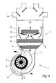
- a blower 1 of a vehicle air conditioning system 2 has an impeller 4 arranged in a blower housing 3 and a blower motor 5.
- the blower 1 sucks controlled via the flaps (not shown) air from the environment (fresh air) via a fresh air duct 6a and air from the vehicle interior (circulating air) via a circulating air duct 6b.
- the two air ducts will hereinafter also be referred to as intake air ducts.
- the intake air ducts 6a, 6b are formed in a Zuströmgephaseuse 22 which is connected as an attachment to the fan housing 3. In the parting plane between the Zuströmgepatuse 22 and blower housing 3, the actual inlet opening 23 of the blower is.
- the regulation of the temperature is carried out in a conventional manner by means of temperature mixing flaps 12, which distribute the cold, coming from the evaporator 10 air flow to the radiator 11 and bypasses 13.
- the thus different tempered partial air streams are mixed in the mixing chamber 14 arranged below and fed to the various areas of the vehicle interior via flap-controlled outlet openings and air ducts 15.
- the embodiment of the air conditioner 2 may be provided deviating from the embodiment in any conventional manner.
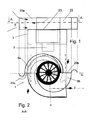
- blower 1 For the description of the blower 1 is hereinafter referred to the Figures 1 and 2 Reference is made, for better clarity in the drawing, the figures are interconnected by dashed lines shown gravity lines.
- the flow patterns of the air are at the entrances and exits from Fig. 2 and at the entrance of the fresh air channel 6a of Fig. 1 illustrated by arrows.
- Fig. 1 how out Fig. 1 can be seen, the fan housing on three stages, in the uppermost stage, the Zuströmgepatuse 22, the fresh and the recirculating air duct 6a, 6b open and the air flow is slightly deflected. In the second, middle stage, the actual volute casing of the blower 1 together with the impeller 4 and the outlet (outlet air duct 7) is arranged. Below this, the blower motor 5 is arranged in the third stage.
- the flow is in this case in the middle perpendicular to the radial direction, the center of the air channels 6 is clearly offset with respect to the impeller 4 to the outside.
- the impeller 4 closest to the wall is slightly offset to the outside.
- the inlet of the air to be conveyed into the corresponding intake ducts 6a, 6b takes place through the associated intake openings 20a, 20b, wherein in the present case the surface normals are arranged on these intake openings 20a, 20b parallel to each other and perpendicular to the rotor axis.
- these surface normals are shown as dash-dotted lines and perpendicular to the respective intake opening 20a, 20b and extending through the center of area thereof.
- the intake openings lie in a common plane, in which the axis of the impeller 4 is located.
- the surface normal through the outlet opening 21 is substantially perpendicular to the surface normals of the suction openings 20a, 20b and to the axis of the impeller 4.
- the sum of the cross section of the intake openings 20a, 20b which in a plane E (see Fig. 2 ), according to the present embodiment corresponds approximately to the cross-sectional area of the impeller in the corresponding plane E, in which also lies the axis of rotation, or substantially the cross section of the inlet opening 23.
- the two intake air ducts 6 spiral the sucked air to the impeller 4, wherein It passes through the above-arranged circular inlet opening 23 - also referred to as a frame opening - from the intake air ducts 6a, 6b to the impeller 4.
- the spiral-shaped configuration of the intake air ducts 6a, 6b generates a pre-whirl which, superimposed with a relatively small linear component, is continued through the door opening and improves the inflow to the impeller blading.
- the air does not move directly to the Zargenö réelle 23, but flows - seen with respect to the center of the intake air duct 6 - tangentially thereto, wherein a total of one skew arrangement of the axis of rotation of the impeller 4 (center of the Zargenö réelle) and the surface normal on the suction port 21 a, 21 b of an intake passage 6 is present.
- Such a configuration results in a vortex-like rotational movement into the frame opening.
- an air blower is provided, however, a corresponding embodiment for other fluids, such as. Gases or water, applicable and also not necessarily limited to air conditioning.
- the fan housing has three stages, wherein in the uppermost stage, the Zuströmgepatuse 22, the fresh and the recirculating air duct 6a, 6b open and the air flow is slightly deflected.
- the suction openings 20a, 20b are no longer inclined in a common, but at an angle of about 80 ° to each other.
- This also applies to the corresponding surface normals, which in Fig. 5 again shown as dash-dotted lines.
- the suction port 20a formed on the left side is opposed to the suction port 20b on the right side in a plane offset from the rotation axis.
- the axis of rotation of the impeller 4 is also parallel to this plane.
Landscapes
- Engineering & Computer Science (AREA)
- Mechanical Engineering (AREA)
- General Engineering & Computer Science (AREA)
- Structures Of Non-Positive Displacement Pumps (AREA)
Abstract
Description
- Die Erfindung betrifft ein Gebläse, insbesondere für die Frisch- und/oder Umluftansaugung einer Fahrzeugklimaanlage, gemäß dem Oberbegriff des Anspruches 1.
- Bei herkömmlichen Gebläsen mit einer Ansaugung von Frisch- und/oder Umluft wird die Luft oft in radialer Richtung, d.h. senkrecht zur Drehachse des Gebläsemotors, angesaugt.
- Die
DE 1 428 085 A1 offenbart ein Trommelläufer-Gebläse mit einem Gehäuse, welches im Wesentlichen einseitig offen ist und von dort her Luft ansaugt. Das Laufrad läuft bereichsweise frei, d.h. ohne eine Abdeckung. Hierbei ist eine äußere Leitfläche vorgesehen, welche etwa die Hälfte des Laufradumfangs umfasst. Die Luftansaugung erfolgt über den offenen Bereich des Gebläses sowohl in radialer als auch axialer Richtung. - Ferner ist aus der
DE 198 47 158 A1 eine Gebläseanordnung für die Frisch- und/oder Umluftansaugung einer Fahrzeugklimaanlage bekannt, wobei diese Gebläseanordnung jeweils getrennte Laufräder für Frisch- und Umluft sowohl auf der Fahrer- als auch auf der Beifahrerseite aufweist. - Ein derartiges Gebläse lässt noch Wünsche offen.
- Es ist Aufgabe der Erfindung, ein verbessertes Gebläse zur Verfügung zu stellen.
- Diese Aufgabe wird gelöst durch ein Gebläse mit den Merkmalen des Anspruchs 1. Vorteilhafte Ausgestaltungen sind Gegenstand der Unteransprüche.
- Die Erfindung betrifft ein Gebläse, insbesondere für die Frisch- und/oder Umluftansaugung für eine Fahrzeugklimaanlage, mit einem Gebläsegehäuse, einem Laufrad mit einer Drehachse und einem das Laufrad antreibenden Gebläsemotor, wobei das Gebläsegehäuse mindestens eine Ansaugöffnung für einen Ansaugkanal und eine Austriftsöffnung für einen Austrittskanal aufweist. Hierbei ist die Flächennormale auf die Ansaugöffnung des Ansaugkanals windschief bezüglich der Drehachse des Laufrades und die Ansaugöffnung in einer in Richtung der Drehachse des Laufrads versetzten Ebene zur Austrittsöffnung angeordnet. Das seitliche Anströmen der Luft bewirkt einen Vordrall und verbessert so die Zuströmung zum Laufrad bzw. zur Laufradbeschaufelung. Geschwindigkeitsspitzen beim Umströmen des Zargenrandes durch starke Umlenkung können vermieden werden, wodurch sich eine Geräuschreduzierung ergibt.
- Bevorzugt ist die Flächennormale auf die Ansaugöffnung parallel zu einer Ebene angeordnet, in welcher die Drehachse des Laufrads liegt, wobei die Mittellängsachse des Ansaugkanals insbesondere etwa tangential zur vorzugsweise kreisrunden Eintrittsöffnung zum Laufrad angeordnet ist. Durch ein tangentiales Anströmen bildet sich ein Wirbel aus, welcher sich durch die Eintrittsöffnung in Richtung Laufrad erstreckt, wodurch sich eine verbesserte Anströmung zum Laufrad ergibt und Strömungsgeräusche verringert werden können.
- Eine Ebene, in welcher eine Ansaugöffnung liegt, schließt bevorzugt die Drehachse des Laufrades mit ein. Alternativ oder im Falle mehrerer Ansaugöffnungen, ist eine solche Ebene, in der eine Ansaugöffnung liegt bevorzugt auch parallel versetzt zur Drehachse des Laufrades ausgebildet.
- Insbesondere bevorzugt weist der Ansaugkanal in einer Ebene, die sich senkrecht zur Drehachse des Laufrades erstreckt, eine Breite auf, welche maximal der Breite der Eintrittsöffnung oder für den Fall einer kreisrunden Öffnung dem Durchmesser der Eintrittsöffnung zum Laufrad entspricht.
- Der Gebläsemotor ist bevorzugt auf der entgegengesetzten Seite des Laufrads in Bezug auf den oder die Ansaugkanäle angeordnet.
- Besonders bevorzugt sind zwei Ansaugkanäle, insbesondere ein Frischluft- und ein Umluftkanal, vorgesehen, so dass eine Ansaugung aus zwei Richtungen realisiert werden kann.
- Die Flächennormalen der Ansaugöffnungen sind vorteilhafterweise in einem Winkel von 0° bis 90° zueinander angeordnet.
- Bevorzugt sind die Ansaugöffnungen auf einander gegenüberliegenden Seiten der Drehachse des Laufrades angeordnet und verlaufen insbesondere in einer Ebene.
- Zweckmäßigerweise sind die Ansaugkanäle in einem Zuströmgehäuse ausgebildet, wobei das Zuströmgehäuse bevorzugt in axialer Richtung der Drehachse des Laufrads an das Gebläsegehäuse anschließt. Insbesondere sind das Zuströmgehäuse und das Gebläsegehäuse als separate Bauteile ausgebildet sind, wobei das Zuströmgehäuse einen Aufsatz oder Vorbau zum Gebläsegehäuse darstellt.
- Die Ansaugkanäle sind bevorzugt gleichmäßig über den Umfang einer Eintrittsöffnung zum Laufrad angeordnet. Im Falle von zwei Ansaugkanälen liegen dieselben einander diagonal gegenüber, wobei die Mittellängsachsen der beiden Ansaugkanäle gemäß einer bevorzugten Ausführungsform parallel und beabstandet zueinander angeordnet sind. Hierbei ist auch eine parallele Anordnung der Ansaugkanäle zueinander möglich.
- Ein derartiges Gebläse wird vorzugsweise in einer Fahrzeug-Klimaanlage verwendet, jedoch kann das Gebläse auch beispielsweise für ein reines Heizungs- oder Belüftungssystem eines Fahrzeugs verwendet werden. Ebenso kann das Gebläse auch in der chemischen Industrie zur Förderung von Gasen oder in der Raumlufttechnik verwendet werden.
- Im Folgenden wird die Erfindung anhand von einem Ausführungsbeispiel unter Bezugnahme auf die Zeichnung im Einzelnen erläutert. Es zeigen:
- Fig. 1
- eine Draufsicht auf ein Gebläse gemäß dem ersten Ausführungsbeispiel,
- Fig. 2
- einen Schnitt entlang Linie A-A von
Fig. 1 , und - Fig. 3
- eine schematische Ansicht des Gebläses entsprechend
Fig. 2 samt angedeuteter Frisch- und Umluftansaugung und nachfolgend angeordneter Klimaanlage. - Fig. 4
- eine Draufsicht auf ein Gebläse gemäß dem zweiten Ausführungsbeispiel,
- Fig. 5
- einen Schnitt entlang Linie A-A von
Fig. 4 , und - Ein Gebläse 1 einer Fahrzeugklimaanlage 2 weist ein in einem Gebläsegehäuse 3 angeordnetes Laufrad 4 sowie einen Gebläsemotor 5 auf. Das Gebläse 1 saugt über Klappen (nicht dargestellt) geregelt Luft aus der Umgebung (Frischluft) über einen Frischluftkanal 6a und Luft aus dem Fahrzeuginnenraum (Umluft) über einen Umluftkanal 6b an. Auf die beiden Luftkanäle wird im Folgenden auch als Ansaugluftkanäle Bezug genommen.
- Die Ansaugluftkanäle 6a, 6b sind in einem Zuströmgehäuse 22 ausgebildet, das als Aufsatz mit dem Gebläsegehäuse 3 verbunden ist. In der Trennebene zwischen dem Zuströmgehäuse 22 und Gebläsegehäuse 3 befindet sich die eigentliche Eintrittsöffnung 23 des Gebläses.
- Die über die beiden Luftkanäle 6a, 6b angesaugte Luft gelangt nach Durchströmen des Gebläses 1 über einen Austrittsluftkanal 7 direkt in den folgenden Bereich des Klimaanlagengehäuses 8, in welchem ein Filter 9, ein Verdampfer 10 und ein Heizkörper 11 angeordnet sind. Die Regelung der Temperatur erfolgt auf herkömmliche Weise mittels Temperaturmischklappen 12, welche den kalten, vom Verdampfer 10 kommenden Luftstrom auf den Heizkörper 11 und Bypässe 13 verteilen. Die dadurch unterschiedliche temperierten Teilluftströme werden im nachfolgend angeordneten Mischraum 14 vermischt und über klappengeregelte Auslassöffnungen und Luftkanäle 15 den verschiedenen Bereichen des Fahrzeuginnenraums zugeführt. Die Ausgestaltung der Klimaanlage 2 kann abweichend vom Ausführungsbeispiel auf beliebige herkömmliche Weise vorgesehen sein.
- Für die Beschreibung des Gebläses 1 wird im Folgenden auf die
Figuren 1 und 2 Bezug genommen, wobei zur besseren Ersichtlichkeit in der Zeichnung die Figuren durch gestrichelt dargestellte Schwerelinien miteinander verbunden sind. Die Strömungsverläufe der Luft sind an den Ein- und Austritten vonFig. 2 und am Eintritt des Frischluftkanals 6a vonFig. 1 durch Pfeile verdeutlicht. - Wie aus
Fig. 1 ersichtlich, weist das Gebläsegehäuse drei Stufen auf, wobei in der obersten Stufe, dem Zuströmgehäuse 22, der Frisch- und der Umluftkanal 6a, 6b einmünden und die Luftströmung etwas umgelenkt wird. In der zweiten, mittleren Stufe ist das eigentliche Spiralgehäuse des Gebläses 1 samt Laufrad 4 sowie der Austritt (Austrittsluftkanal 7) angeordnet. Unterhalb hiervon ist in der dritten Stufe der Gebläsemotor 5 angeordnet. Hierbei ist, wie ausFig. 2 deutlich ersichtlich, sowohl der Frisch- als auch der Umluftkanal 6a, 6b seitlich versetzt bezüglich der Drehachse des Laufrades 4 und etwas oberhalb desselben angeordnet, wobei die beiden Ansaugluftkanäle 6 gemäß dem vorliegenden Ausführungsbeispiel in ihrer Anordnung punktsymmetrisch zueinander bezüglich der Drehachse des Laufrades 4 angeordnet sind, d.h. sie sind an diagonal zueinander angeordneten Seiten oberhalb des Laufrades 4 angeordnet. Die Anströmung erfolgt hierbei im Mittel senkrecht zur radialen Richtung, wobei die Mitte der Luftkanäle 6 deutlich bezüglich des Laufrades 4 nach außen versetzt ist. Vorliegend ist auch die dem Laufrad 4 am Nächsten kommende Wand leicht nach außen versetzt. - Der Eintritt der zu fördernden Luft in die entsprechenden Ansaugkanäle 6a, 6b erfolgt durch die zugeordneten Ansaugöffnungen 20a, 20b, wobei vorliegend die Flächennormalen auf diese Ansaugöffnungen 20a, 20b.parallel zueinander und senkrecht zur Laufradachse angeordnet sind. In
Fig. 2 sind diese Flächennormalen als strichpunktierte Linien dargestellt und senkrecht zur jeweiligen Ansaugöffnung 20a, 20b und durch den Flächenmittelpunkt derselben verlaufend. In dem gezeigten ersten Ausführungsbeispiel liegen die Ansaugöffnungen in einer gemeinsamen Ebene, in der auch die Achse des Laufrads 4 liegt. Die Flächennormale durch die Austrittöffnung 21 ist im Wesentlichen senkrecht zu den Flächennormalen der Ansaugöffnungen 20a, 20b, sowie zur Achse des Laufrades 4. - Die Summe des Querschnitts der Ansaugöffnungen 20a, 20b welche in einer Ebene E (siehe
Fig. 2 ) liegen, entspricht gemäß dem vorliegenden Ausführungsbeispiel annährend der Querschnittsfläche des Laufrads in der entsprechenden Ebene E, in welcher auch die Drehachse liegt, bzw. im Wesentlichen dem Querschnitt der Eintrittsöffnung 23. Die beiden Ansaugluftkanäle 6 führen spiralförmig die angesaugte Luft zum Laufrad 4, wobei sie über die oben angeordnete kreisförmige Eintrittsöffnung 23 - auch als Zargenöffnung bezeichnet - aus den Ansaugluftkanälen 6a, 6b zum Laufrad 4 gelangt. - Durch die spiralförmige Ausgestaltung der Ansaugluftkanäle 6a, 6b wird ein Vordrall erzeugt, welcher - überlagert mit einer relativ kleinen Linearkomponente - durch die Zargenöffnung hinweg weitergeführt wird, und die Zuströmung zur Laufradbeschaufelung verbessert. Hierbei bewegt sich die Luft also nicht direkt auf die Zargenöffnung 23 zu, sondern strömt - in Bezug auf die Mitte des Ansaugluftkanals 6 gesehen - tangential hierzu an, wobei insgesamt jeweils eine windschiefe Anordnung von Drehachse des Laufrades 4 (Mitte der Zargenöffnung) und der Flächennormalen auf die Ansaugöffnung 21 a, 21 b eines Ansaugkanals 6 vorliegt. Durch eine derartige Ausgestaltung ergibt sich eine wirbelartige Drehbewegung in die Zargenöffnung hinein.
- An Stelle einer parallelen Anordnung der Ansaugluftkanäle in einer Ebene ist auch eine Anordnung in verschiedenen Ebenen oder eine ungleichmäßige Verteilung der Ansaugluftkanäle möglich.
- Beim vorstehend beschriebenen Ausführungsbeispiel ist ein Luftgebläse vorgesehen, jedoch ist eine entsprechende Ausgestaltung auch für andere Fluide, wie bspw. Gase oder Wasser, anwendbar und zudem nicht notwendigerweise auf Klimaanlagen beschränkt.
- In einem zweiten Ausführungsbeispiel eines Gebläses 1 einer Fahrzeugklimaanlage 2 ist, wie in den
Figuren 4 und 5 dargestellt, eine alternative Anordnung der Ansaugöffnungen 20a, 20b zueinander dargestellt. Die Bezugszeichen entsprechen sofern sie funktional gleichwirkende Bauteile betreffen, den Bezugszeichen die bereits für das erste Ausführungsbeispiel Verwendung fanden. - Wie auch im ersten Ausführungsbeispiel, weist das Gebläsegehäuse drei Stufen auf, wobei in der obersten Stufe, dem Zuströmgehäuse 22, der Frisch- und der Umluftkanal 6a, 6b einmünden und die Luftströmung etwas umgelenkt wird. Im Unterschied zum ersten Ausführungsbeispiel sind die Ansaugöffnungen 20a, 20b nicht mehr in einer gemeinsamen, sondern in einem Winkel von etwa 80° zueinander geneigt. Ebenso gilt dies selbstverständlich auch für die entsprechenden Flächennormalen, die in
Fig. 5 wiederum als strichpunktierte Linien dargestellt sind. Die auf der linken Seite ausgebildete Ansaugöffnung 20a liegt im Gegensatz zur Ansaugöffnung 20b auf der rechten Seite in einer Ebene, die versetzt zur Drehachse angeordnet ist. Die Drehachse des Laufrads 4 ist zu dieser Ebene allerdings ebenfalls parallel. - Beliebige andere Winkel der Ansaugkanäle und damit auch der Ansauföffnungen zueinander sind möglich, jedoch sollten hierbei kurz vor der Eintrittsöffnung zum Laufrad keine wesentlichen Richtungsumlenkungen o.ä. vorgesehen sein.
Claims (12)
- Gebläse, insbesondere für die Frisch- und/oder Umluftansaugung für eine Fahrzeugklimaanlage, mit einem Gebläsegehäuse (3), einem Laufrad (4) mit einer Drehachse und einem das Laufrad (4) antreibenden Gebläsemotor (5), wobei das Gebläsegehäuse (3) mindestens eine Ansaugöffnung (20) für einen Ansaugkanal (6) und einer Austrittsöffnung (21) für einen Austrittskanal (7) aufweist, dadurch gekennzeichnet, dass die Flächennormale auf die Ansaugöffnung (20) des Ansaugkanals (6) windschief bezüglich der Drehachse des Laufrades (4) und die Ansaugöffnung (20) in einer in Richtung der Drehachse des Laufrads (4) versetzten Ebene zur Austrittsöffnung (21) angeordnet ist.
- Gebläse nach einem der vorhergehenden Ansprüche, dadurch gekennzeichnet, dass die Flächennormale auf die Ansaugöffnung (20) parallel zu einer Ebene angeordnet ist, in welcher die Drehachse des Laufrads (4) liegt, wobei insbesondere die Mittellängsachse des Ansaugkanals (6) etwa tangential zur Eintrittsöffnung zum Laufrad (4) angeordnet ist.
- Gebläse nach einem der vorhergehenden Ansprüche, dadurch gekennzeichnet, dass der Gebläsemotor (5) auf der entgegengesetzten Seite des Laufrads (4) in Bezug auf den oder die Ansaugkanäle (6) angeordnet ist.
- Gebläse nach einem der vorhergehenden Ansprüche, dadurch gekennzeichnet, dass zwei Ansaugkanäle (6a, 6b) mit jeweils einer zugeordneten Ansaugöffnung (20a, 20b) vorgesehen sind.
- Gebläse nach Anspruch 4, dadurch gekennzeichnet, dass die Flächennormalen der Ansaugöffnungen (20a, 20b) in einem Winkel von 0° bis 90° zueinander angeordnet sind.
- Gebläse nach Anspruch 4 oder 5, dadurch gekennzeichnet, dass die Ansaugöffnungen (20a, 20b) auf einander gegenüberliegenden Seiten der Drehachse des Laufrades (4) angeordnet sind.
- Gebläse nach einem der Ansprüche 4 bis 6, dadurch gekennzeichnet, dass die Ansaugöffnungen (20a, 20b) in einer Ebene angeordnet sind.
- Gebläse nach einem der Ansprüche 4 bis 7, dadurch gekennzeichnet, dass die Ansaugkanäle (6a, 6b) in einem Zuströmgehäuse (22) angeordnet sind.
- Gebläse nach Anspruch 8, dadurch gekennzeichnet, dass das Zuströmgehäuse (22) in axialer Richtung der Drehachse des Laufrads (4) an das Gebläsegehäuse (3) anschließt.
- Gebläse nach einem der Ansprüche 8 oder 9, dadurch gekennzeichnet, dass das Zuströmgehäuse (22) und das Gebläsegehäuse (3) als separate Bauteile ausgebildet sind.
- Gebläse nach einem der vorhergehenden Ansprüche, dadurch gekennzeichnet, dass das Gebläse (1) ein Gebläse für gasförmige Medien, insbesondere Luft, ist.
- Fahrzeugklimaanlage (2), gekennzeichnet durch ein Gebläse (1) nach einem der Ansprüche 1 bis 11.
Applications Claiming Priority (1)
| Application Number | Priority Date | Filing Date | Title |
|---|---|---|---|
| DE102008004746A DE102008004746A1 (de) | 2008-01-16 | 2008-01-16 | Gebläse, insbesondere für die Frisch- und/oder Umluftansaugung einer Fahrzeugklimaanlage |
Publications (3)
| Publication Number | Publication Date |
|---|---|
| EP2080910A2 true EP2080910A2 (de) | 2009-07-22 |
| EP2080910A3 EP2080910A3 (de) | 2013-11-06 |
| EP2080910B1 EP2080910B1 (de) | 2018-06-20 |
Family
ID=40139929
Family Applications (1)
| Application Number | Title | Priority Date | Filing Date |
|---|---|---|---|
| EP08020487.8A Ceased EP2080910B1 (de) | 2008-01-16 | 2008-11-26 | Gebläse, insbesondere Fahrzeuggebläse |
Country Status (2)
| Country | Link |
|---|---|
| EP (1) | EP2080910B1 (de) |
| DE (1) | DE102008004746A1 (de) |
Cited By (1)
| Publication number | Priority date | Publication date | Assignee | Title |
|---|---|---|---|---|
| US20160153666A1 (en) * | 2013-09-10 | 2016-06-02 | Electrolux Appliances Aktiebolag | Cooling and exhaust system for a cooking oven |
Citations (2)
| Publication number | Priority date | Publication date | Assignee | Title |
|---|---|---|---|---|
| DE1428085A1 (de) | 1962-02-08 | 1970-12-03 | Eck Dr Ing Bruno | Trommellaeufer-Geblaese,insbesondere fuer freies Ausblasen |
| DE19847158A1 (de) | 1997-10-14 | 1999-04-15 | Denso Corp | Klimaanlage für ein Fahrzeug |
Family Cites Families (13)
| Publication number | Priority date | Publication date | Assignee | Title |
|---|---|---|---|---|
| US2336010A (en) * | 1942-09-17 | 1943-12-07 | Fairchild Engine & Airplane | Supercharger |
| GB575909A (en) * | 1944-04-17 | 1946-03-11 | Henry Withers Kickweed Jenning | Improvements relating to centrifugal fans |
| FR2762804B1 (fr) * | 1997-04-30 | 1999-07-02 | Valeo Climatisation | Dispositif de chauffage-ventilation des places arriere d'un vehicule automobile, notamment de type monospace |
| FR2781844B1 (fr) * | 1998-08-03 | 2000-09-22 | Valeo Climatisation | Groupe moto-ventilateur a caracteristiques aerauliques ameliorees, notamment pour installation de chauffage-climatisation de vehicule automobile |
| DE10052893A1 (de) * | 2000-08-24 | 2002-03-21 | Mtm Motorentechnik Mayer Gmbh | Vorrichtung zur Verbesserung des Wirkungsgrads von vorzugsweise in Kraftfahrzeugen eingebauten Strömungsmaschinen |
| DE10158874A1 (de) * | 2001-11-30 | 2003-06-12 | Daimler Chrysler Ag | Abgasturbolader für eine Brennkraftmaschine und Verfahren zum Betrieb einer aufgeladenen Brennkraftmaschine |
| US6789999B2 (en) * | 2002-06-11 | 2004-09-14 | Valeo Climate Control Corp | Center console dual centrifugal fan blower |
| DE10256619B3 (de) * | 2002-12-03 | 2004-01-22 | Iav Gmbh Ingenieurgesellschaft Auto Und Verkehr | Klimagerät für Fahrzeuge |
| DE60309003T2 (de) * | 2003-05-28 | 2007-05-24 | Ford Global Technologies, LLC, Dearborn | Aufgeladener Verbrennungsmotor |
| EP1632678A1 (de) * | 2004-09-01 | 2006-03-08 | Ford Global Technologies, LLC, A subsidary of Ford Motor Company | Drallgenerator in Bögen |
| DE102005023647B4 (de) * | 2005-05-21 | 2014-09-04 | Daimler Ag | Abgasturbolader mit einem Verdichter |
| US7682233B2 (en) * | 2005-06-17 | 2010-03-23 | Halla Climate Control Corporation | Blower for air conditioner of automotive vehicles |
| DE102006019328A1 (de) * | 2006-04-24 | 2007-10-25 | Behr Gmbh & Co. Kg | Ansauggebläseanordnung, insbesondere für eine Kraftfahrzeug-Klimaanlage |
-
2008
- 2008-01-16 DE DE102008004746A patent/DE102008004746A1/de not_active Withdrawn
- 2008-11-26 EP EP08020487.8A patent/EP2080910B1/de not_active Ceased
Patent Citations (2)
| Publication number | Priority date | Publication date | Assignee | Title |
|---|---|---|---|---|
| DE1428085A1 (de) | 1962-02-08 | 1970-12-03 | Eck Dr Ing Bruno | Trommellaeufer-Geblaese,insbesondere fuer freies Ausblasen |
| DE19847158A1 (de) | 1997-10-14 | 1999-04-15 | Denso Corp | Klimaanlage für ein Fahrzeug |
Cited By (1)
| Publication number | Priority date | Publication date | Assignee | Title |
|---|---|---|---|---|
| US20160153666A1 (en) * | 2013-09-10 | 2016-06-02 | Electrolux Appliances Aktiebolag | Cooling and exhaust system for a cooking oven |
Also Published As
| Publication number | Publication date |
|---|---|
| EP2080910A3 (de) | 2013-11-06 |
| EP2080910B1 (de) | 2018-06-20 |
| DE102008004746A1 (de) | 2009-07-23 |
Similar Documents
| Publication | Publication Date | Title |
|---|---|---|
| CH669431A5 (de) | ||
| EP2226473A2 (de) | Luftleitelement eines Laufspalteinstellungssystems einer Fluggasturbine | |
| WO2014170398A1 (de) | Kraftfahrzeug-motorkühlung-lüfterzarge mit staudruckklappen | |
| EP3141410A1 (de) | Luftführungsgehäuse und eine belüftungs-, heizungs- oder klimaanlage mit einem solchen luftführungsgehäuse | |
| EP2000337A2 (de) | Gebläseanordnung zur Belüftung eines Fahrzeugs | |
| EP1312493B1 (de) | Luftmischeinrichtung für eine Heizungs- oder Klimaanlage | |
| DE602006000387T2 (de) | Doppelgebläseanordnung für Kraftfahrzeuge | |
| EP2080910B1 (de) | Gebläse, insbesondere Fahrzeuggebläse | |
| DE10256619B3 (de) | Klimagerät für Fahrzeuge | |
| DE102009040545A1 (de) | Zentrifugalgebläse | |
| DE3740132C2 (de) | ||
| DE102004010632A1 (de) | Kraftfahrzeug mit doppeltem Kühler | |
| DE102004015829B4 (de) | Ansaugstutzen | |
| DE3905092C2 (de) | ||
| EP2388159B1 (de) | Kraftfahrzeugklimaanlage | |
| DE102008035403A1 (de) | Klimaanlage mit Gebläse in einer Land- oder Baumaschine | |
| EP3486494B1 (de) | Radialgebläsegehäuse und radialgebläse | |
| DE102008010182A1 (de) | Gehäuse für eine Gasfördereinrichtung | |
| EP1400381B1 (de) | Mischvorrichtung zum Mischen von kalter und warmer Luft, insbesondere für eine Heizungs- oder Klimaanlage eines Kraftfahrzeugs | |
| EP1717070B1 (de) | Lüftungsvorrichtung, insbesondere für ein Kraftfahrzeug | |
| EP1518731B1 (de) | Gebläse-Filter-Einheit | |
| DE3814233C2 (de) | ||
| EP1510764B1 (de) | Lüftungseinrichtung und Verfahren zu ihrem Betrieb | |
| DE10333184A1 (de) | Lüftungsgebläse | |
| DE102007023232A1 (de) | Luftführungseinrichtung an einem Personenkraftwagen |
Legal Events
| Date | Code | Title | Description |
|---|---|---|---|
| PUAI | Public reference made under article 153(3) epc to a published international application that has entered the european phase |
Free format text: ORIGINAL CODE: 0009012 |
|
| AK | Designated contracting states |
Kind code of ref document: A2 Designated state(s): AT BE BG CH CY CZ DE DK EE ES FI FR GB GR HR HU IE IS IT LI LT LU LV MC MT NL NO PL PT RO SE SI SK TR |
|
| AX | Request for extension of the european patent |
Extension state: AL BA MK RS |
|
| PUAL | Search report despatched |
Free format text: ORIGINAL CODE: 0009013 |
|
| AK | Designated contracting states |
Kind code of ref document: A3 Designated state(s): AT BE BG CH CY CZ DE DK EE ES FI FR GB GR HR HU IE IS IT LI LT LU LV MC MT NL NO PL PT RO SE SI SK TR |
|
| AX | Request for extension of the european patent |
Extension state: AL BA MK RS |
|
| RIC1 | Information provided on ipc code assigned before grant |
Ipc: F04D 29/42 20060101AFI20131002BHEP |
|
| 17P | Request for examination filed |
Effective date: 20140506 |
|
| RBV | Designated contracting states (corrected) |
Designated state(s): AT BE BG CH CY CZ DE DK EE ES FI FR GB GR HR HU IE IS IT LI LT LU LV MC MT NL NO PL PT RO SE SI SK TR |
|
| AKX | Designation fees paid |
Designated state(s): DE |
|
| RAP1 | Party data changed (applicant data changed or rights of an application transferred) |
Owner name: MAHLE BEHR GMBH & CO. KG |
|
| 17Q | First examination report despatched |
Effective date: 20160513 |
|
| GRAP | Despatch of communication of intention to grant a patent |
Free format text: ORIGINAL CODE: EPIDOSNIGR1 |
|
| INTG | Intention to grant announced |
Effective date: 20180208 |
|
| GRAS | Grant fee paid |
Free format text: ORIGINAL CODE: EPIDOSNIGR3 |
|
| GRAA | (expected) grant |
Free format text: ORIGINAL CODE: 0009210 |
|
| AK | Designated contracting states |
Kind code of ref document: B1 Designated state(s): DE |
|
| RIN1 | Information on inventor provided before grant (corrected) |
Inventor name: LANG, MATTHIAS |
|
| REG | Reference to a national code |
Ref country code: DE Ref legal event code: R096 Ref document number: 502008016140 Country of ref document: DE |
|
| PGFP | Annual fee paid to national office [announced via postgrant information from national office to epo] |
Ref country code: DE Payment date: 20181203 Year of fee payment: 11 |
|
| REG | Reference to a national code |
Ref country code: DE Ref legal event code: R097 Ref document number: 502008016140 Country of ref document: DE |
|
| PLBE | No opposition filed within time limit |
Free format text: ORIGINAL CODE: 0009261 |
|
| STAA | Information on the status of an ep patent application or granted ep patent |
Free format text: STATUS: NO OPPOSITION FILED WITHIN TIME LIMIT |
|
| 26N | No opposition filed |
Effective date: 20190321 |
|
| REG | Reference to a national code |
Ref country code: DE Ref legal event code: R119 Ref document number: 502008016140 Country of ref document: DE |
|
| PG25 | Lapsed in a contracting state [announced via postgrant information from national office to epo] |
Ref country code: DE Free format text: LAPSE BECAUSE OF NON-PAYMENT OF DUE FEES Effective date: 20200603 |