EP1510764B1 - Lüftungseinrichtung und Verfahren zu ihrem Betrieb - Google Patents
Lüftungseinrichtung und Verfahren zu ihrem Betrieb Download PDFInfo
- Publication number
- EP1510764B1 EP1510764B1 EP03405618A EP03405618A EP1510764B1 EP 1510764 B1 EP1510764 B1 EP 1510764B1 EP 03405618 A EP03405618 A EP 03405618A EP 03405618 A EP03405618 A EP 03405618A EP 1510764 B1 EP1510764 B1 EP 1510764B1
- Authority
- EP
- European Patent Office
- Prior art keywords
- ventilation device
- inlet
- outlet
- section
- channel
- Prior art date
- Legal status (The legal status is an assumption and is not a legal conclusion. Google has not performed a legal analysis and makes no representation as to the accuracy of the status listed.)
- Expired - Lifetime
Links
- 238000009423 ventilation Methods 0.000 title claims abstract description 40
- 238000011017 operating method Methods 0.000 title 1
- 238000005192 partition Methods 0.000 claims description 17
- 238000011144 upstream manufacturing Methods 0.000 claims description 4
- 238000000034 method Methods 0.000 claims description 2
- 239000002699 waste material Substances 0.000 claims 3
- 238000009413 insulation Methods 0.000 description 3
- 229910052751 metal Inorganic materials 0.000 description 2
- 239000002184 metal Substances 0.000 description 2
- RYGMFSIKBFXOCR-UHFFFAOYSA-N Copper Chemical compound [Cu] RYGMFSIKBFXOCR-UHFFFAOYSA-N 0.000 description 1
- 229920005830 Polyurethane Foam Polymers 0.000 description 1
- 229910000831 Steel Inorganic materials 0.000 description 1
- WYTGDNHDOZPMIW-RCBQFDQVSA-N alstonine Natural products C1=CC2=C3C=CC=CC3=NC2=C2N1C[C@H]1[C@H](C)OC=C(C(=O)OC)[C@H]1C2 WYTGDNHDOZPMIW-RCBQFDQVSA-N 0.000 description 1
- 229910052782 aluminium Inorganic materials 0.000 description 1
- XAGFODPZIPBFFR-UHFFFAOYSA-N aluminium Chemical compound [Al] XAGFODPZIPBFFR-UHFFFAOYSA-N 0.000 description 1
- 230000015572 biosynthetic process Effects 0.000 description 1
- 239000004020 conductor Substances 0.000 description 1
- 238000010276 construction Methods 0.000 description 1
- 238000001816 cooling Methods 0.000 description 1
- 229910052802 copper Inorganic materials 0.000 description 1
- 239000010949 copper Substances 0.000 description 1
- 239000006260 foam Substances 0.000 description 1
- 230000010354 integration Effects 0.000 description 1
- 238000004519 manufacturing process Methods 0.000 description 1
- 239000000463 material Substances 0.000 description 1
- 150000002739 metals Chemical class 0.000 description 1
- 238000012986 modification Methods 0.000 description 1
- 230000004048 modification Effects 0.000 description 1
- 239000004033 plastic Substances 0.000 description 1
- 229920003023 plastic Polymers 0.000 description 1
- 239000011496 polyurethane foam Substances 0.000 description 1
- 239000010959 steel Substances 0.000 description 1
- 239000002023 wood Substances 0.000 description 1
Images

Classifications
-
- F—MECHANICAL ENGINEERING; LIGHTING; HEATING; WEAPONS; BLASTING
- F28—HEAT EXCHANGE IN GENERAL
- F28F—DETAILS OF HEAT-EXCHANGE AND HEAT-TRANSFER APPARATUS, OF GENERAL APPLICATION
- F28F9/00—Casings; Header boxes; Auxiliary supports for elements; Auxiliary members within casings
- F28F9/02—Header boxes; End plates
- F28F9/026—Header boxes; End plates with static flow control means, e.g. with means for uniformly distributing heat exchange media into conduits
- F28F9/0265—Header boxes; End plates with static flow control means, e.g. with means for uniformly distributing heat exchange media into conduits by using guiding means or impingement means inside the header box
-
- F—MECHANICAL ENGINEERING; LIGHTING; HEATING; WEAPONS; BLASTING
- F24—HEATING; RANGES; VENTILATING
- F24F—AIR-CONDITIONING; AIR-HUMIDIFICATION; VENTILATION; USE OF AIR CURRENTS FOR SCREENING
- F24F12/00—Use of energy recovery systems in air conditioning, ventilation or screening
- F24F12/001—Use of energy recovery systems in air conditioning, ventilation or screening with heat-exchange between supplied and exhausted air
- F24F12/006—Use of energy recovery systems in air conditioning, ventilation or screening with heat-exchange between supplied and exhausted air using an air-to-air heat exchanger
-
- F—MECHANICAL ENGINEERING; LIGHTING; HEATING; WEAPONS; BLASTING
- F28—HEAT EXCHANGE IN GENERAL
- F28F—DETAILS OF HEAT-EXCHANGE AND HEAT-TRANSFER APPARATUS, OF GENERAL APPLICATION
- F28F9/00—Casings; Header boxes; Auxiliary supports for elements; Auxiliary members within casings
- F28F9/22—Arrangements for directing heat-exchange media into successive compartments, e.g. arrangements of guide plates
-
- Y—GENERAL TAGGING OF NEW TECHNOLOGICAL DEVELOPMENTS; GENERAL TAGGING OF CROSS-SECTIONAL TECHNOLOGIES SPANNING OVER SEVERAL SECTIONS OF THE IPC; TECHNICAL SUBJECTS COVERED BY FORMER USPC CROSS-REFERENCE ART COLLECTIONS [XRACs] AND DIGESTS
- Y02—TECHNOLOGIES OR APPLICATIONS FOR MITIGATION OR ADAPTATION AGAINST CLIMATE CHANGE
- Y02B—CLIMATE CHANGE MITIGATION TECHNOLOGIES RELATED TO BUILDINGS, e.g. HOUSING, HOUSE APPLIANCES OR RELATED END-USER APPLICATIONS
- Y02B30/00—Energy efficient heating, ventilation or air conditioning [HVAC]
- Y02B30/56—Heat recovery units
Definitions
- the invention relates to a ventilation device according to the preamble of claim 1.
- Such ventilation devices make it possible to replace exhaust air from a closed space by supply air supplied from the outside, which exchanges heat with the exhaust air.
- it relates to a method for operating a ventilation device according to the invention.
- Ventilation devices which include a countercurrent heat exchanger. So is out of the EP 1 308 678 A1 a generic ventilation device which can be installed, for example, in a window, in which a double channel, which consists of a supply air duct and an exhaust duct which is thermally tightly coupled with the same, is guided in a serpentine manner in a cuboid housing.
- the device is very space-saving and can easily be retrofitted. Due to the sharp deflections, the flow is essentially turbulent and the efficiency is relatively high. The length of the double channel can also be easily adapted to the requirements that are placed on the efficiency of the ventilation device.
- a ventilation device which is integrated in a window frame.
- the supply air duct and the exhaust air duct are each almost completely around the window, over a part of the circumference as a double channel, which is deflected at two corners of the window frame in each case by 90 °.
- This arrangement requires a lot of space and is practically only in the described form, ie with integration into a window frame or the like. used.
- the length of the double channel and thus the degree of achievable heat exchange is essentially determined by the dimensions of the window frame.
- the flow is likely to be relatively turbulent, so that the heat transfer, at least if no additional measures are taken, such as heat exchanger fins are provided, rather low because of the formation of flow layers.
- the double channel extends only over one side of the window frame.
- the heat transfer should remain moderately moderate despite heat exchanger fins or concentric guidance of the supply air duct and the exhaust duct.
- a ventilation device which can also be installed, for example, in a spar of a window frame.
- supply air duct and exhaust air duct are divided into straight sub-ducts separated by slats, such that supply air and exhaust air ducts alternate. Therefore, the structure of the device is relatively complex. The more numerous and narrower the subchannels are in terms of effective heat transfer, the higher the flow resistance.
- the invention is based on the object to improve the efficiency of known generic ventilation equipment. This object is solved by the features of claim 1. Claim 18 describes an advantageous mode of operation of the inventive ventilation device.
- the ventilation device according to the invention can be of compact construction and have comparatively low flow resistance. Even annoying noise can be kept very low. It can be simple and inexpensive to produce accordingly.
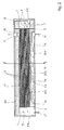
- the ventilation device comprises a cuboid housing with a bottom 1, a ceiling 2, side walls 3a, b and end walls 4a, b.
- the interior of the housing is further divided by two intermediate walls 5, 6 parallel to the end walls 4a, b.
- Between the first intermediate wall 5 and the end wall 4a is a short inlet chamber 7, which is connected by a narrow rectangular air inlet 8 with the outside space.
- In the inlet chamber 8 parallel baffles 9 are installed as turbulence-producing internals to the end wall 4b, which each extend over a part of the cross section.
- a short outlet chamber 10 Between the second intermediate wall 6 and the end wall 4a opposite the end wall 4b is a short outlet chamber 10, which is connected by a rectangular Zuluftauslass 11 in the side wall 3a with the space to be ventilated.
- first partition 5 and the second partition 6 Between the first partition 5 and the second partition 6 is a longer cavity 12 of rectangular cross-section. Laterally spaced parallel tubes 13, which connect the inlet chamber 8 with the outlet chamber 10 are guided by the first partition 5, run, distributed approximately uniformly over the cross section, in the longitudinal direction through the cavity 12 and penetrate the second partition wall 6. On the Inlet chamber 8 side facing away from the first partition 5 a Insulating layer, so that the inlet chamber 8 is thermally insulated from the cavity 12.
- the side wall 3b also has an insulation layer on the inside, which thermally insulates the inlet chamber 8, the cavity 12 and the outlet chamber 10 from the outside space.
- the side wall 3a has an insulation layer inside, so that the inlet chamber 8 is also thermally insulated from the space to be ventilated.
- a partition wall 14 is arranged, which extends from the first partition wall 5 against the second partition wall 6, such that there remains a rectangular passage 15 to the cavity 12 free.
- the side wall 3a is pierced by a rectangular exhaust air inlet 16.
- the opposite side wall 3b, also after the first intermediate wall 5, is penetrated by a rectangular exhaust outlet 17, in which a fan 18 is mounted.
- the cavity 12 forms with the tubes 13 a countercurrent heat exchanger with an exchange section of a Zubucheinlass 8 with the Zu povertyauslass 11 connecting Zu povertykanals formed by the space enclosed by the tubes 13 space, while the remaining part of the cavity 12 has a replacement portion of the exhaust air inlet 16 forms with the exhaust outlet 17 connecting exhaust duct.
- the two exchange sections are through the tubes 13 in close heat-conducting connection.
- the region lying between the side wall 3a and the partition wall 14 forms a supply line section 19 of the latter which connects the exhaust air inlet 16 to the replacement section of the exhaust air channel and, as compared to the replacement section, reaches the passage 15.
- the supply line section 19 is connected to the cavity 12 by a plurality of - in the example three - longitudinally offset short-circuit connections. They are formed by passages formed as narrow slots 20a, b, c in the partition 14. By projections on the partition wall 14, constrictions are respectively applied immediately in front of the slots 20b, c, so that the supply line section 19 widens directly at the slots 20b, c. At the slot 20a, the supply line section 19 also widens, since the partition wall 14 up to this passage comprises a supply line section 19 from the cavity 11 and thus from the exchange section of the exhaust air duct thermally insulating insulation layer and is therefore thicker. Between the slots 20a, b, c and at the passage 15, the lead portion 19 has further constrictions formed by protrusions on the side wall 3a.
- the bottom 1, the lid 2, the side walls 3a, b, the end walls 4a, b, the intermediate walls 5, 6, the baffles 9 and the partition 14 come wood, metal, plastic, pressboard and the like. in question, wherein the insulating layers of foam, e.g. Polyurethane foam can exist.
- the tubes 13 must be made of good heat conducting material. Here are metals such as aluminum, steel or copper.
- the exhaust air flow is shown in the figures by a simple arrow, the supply air flow through a double arrow.
- the fan 18 exhaust air is sucked out of the room to be ventilated through the exhaust duct and ejected.
- the arrangement of the fan 18 in the region of the exhaust outlet 17 noise pollution of the room is largely avoided.
- the exhaust air enters through the exhaust air inlet 16 in the ventilation device and flows through the Supply line section 19 and the replacement section in the cavity 12 to the exhaust outlet 17. Due to the negative pressure generated in the space to be sucked air is supplied to the supply air inlet 8 and passed through the supply air duct and the Zu Kunststoffauslass 11 into the room. Due to leaks in the room, the supply air flow is usually lower than the exhaust air flow.
- a part of the exhaust air flow remains until the passage 15, where it is deflected by 180 ° and passes into the cavity 12, in the supply line section 19, where it is thermally insulated from the exchange section of the supply air duct.
- Other portions thereof are branched off from the supply portion 19 upstream of the passage 15 through the slits 20a, b, c, and further downstream into the exhaust air flow in the cavity 12, i. the replacement section of the exhaust duct. Therefore, parts of the cavity 12 are bridged by the slits 20a, b, c, with the point of entry of the short-circuit connection being located further downstream in the cavity 12, the further upstream their branching point lies in the feed line section 19.
- the bridged portion is relatively short in the case of the slot 20c, but is significantly more than half the length of the cavity 12 in the slot 20a.
- the slots 20a, b, c are dimensioned such that they each branch off about 10-15% of the total exhaust air flow, in total the proportion of the exhaust air flow, which in this way bypasses a smaller or larger part of the replacement section of the exhaust air duct, is approx. 50%. It has been found that this short-circuiting of parts of the replacement section by parts of the exhaust air stream improves the efficiency of the ventilation device in a surprising manner.
Landscapes
- Engineering & Computer Science (AREA)
- Mechanical Engineering (AREA)
- General Engineering & Computer Science (AREA)
- Physics & Mathematics (AREA)
- Thermal Sciences (AREA)
- Combustion & Propulsion (AREA)
- Chemical & Material Sciences (AREA)
- Duct Arrangements (AREA)
- Compressor (AREA)
- Percussion Or Vibration Massage (AREA)
- Heat-Exchange Devices With Radiators And Conduit Assemblies (AREA)
- Devices For Use In Laboratory Experiments (AREA)
- Air Conditioning Control Device (AREA)
- Ventilation (AREA)
Description
- Die Erfindung betrifft eine Lüftungseinrichtung gemäss dem Oberbegriff des Anspruchs 1. Derartige Lüftungseinrichtungen gestatten es, Abluft aus einem geschlossenen Raum durch von aussen zugeführte Zuluft, die dabei mit der Abluft Wärme austauscht, zu ersetzen. Ausserdem betrifft sie ein Verfahren zum Betrieb einer erfindungsgemässen Lüftungseinrichtung.
- Es sind schon viele Lüftungseinrichtungen beschrieben worden, welche einen Gegenstrom-Wärmetauscher umfassen. So ist aus der
EP 1 308 678 A1 eine z.B. in ein Fenster einbaubare gattungsgemässe Lüftungseinrichtung bekannt, bei welcher in einem quaderförmigen Gehäuse ein Doppelkanal, der aus einem Zuluftkanal und einem mit demselben thermisch eng gekoppelten Abluftkanal besteht, serpentinenförmig geführt ist. Die Einrichtung ist sehr platzsparend und kann leicht auch nachträglich eingebaut werden. Durch die scharfen Umlenkungen ist die Strömung im wesentlichen turbulent und der Wirkungsgrad verhältnismässig hoch. Die Länge des Doppelkanals kann ausserdem leicht an die Anforderungen angepasst werden, die hinsichtlich des Wirkungsgrades an die Lüftungseinrichtung gestellt werden. - Aus der
DE 33 47 028 A1 ist eine Lüftungseinrichtung bekannt, welche in einen Fensterrahmen integriert ist. Der Zuluftkanal und der Abluftkanal sind jeweils fast vollständig um das Fenster herumgeführt, über einen Teil des Umfangs als Doppelkanal, der an zwei Ecken des Fensterrahmens jeweils um 90° umgelenkt wird. Diese Anordnung benötigt viel Platz und ist praktisch nur in der beschriebenen Form, also mit Integration in einen Fensterrahmen o.dgl. einsetzbar. Die Länge des Doppelkanals und damit der Grad des erreichbaren Wärmeaustauschs ist wesentlich durch die Abmessungen des Fensterrahmens bestimmt. Die Strömung dürfte verhältnismässig wenig turbulent sein, so dass die Wärmeübertragung, jedenfalls wenn nicht zusätzliche Massnahmen getroffen, z.B. Wärmetauscherrippen vorgesehen werden, wegen der Bildung von Strömungsschichten eher gering bleibt. - Bei einer ähnlichen Lüftungseinrichtung gemäss
DE 32 30 279 A1 erstreckt sich der Doppelkanal nur über eine Seite des Fensterrahmens. Hier dürfte die Wärmeübertragung trotz Wärmetauscherrippen oder konzentrischer Führung des Zuluftkanals und des Abluftkanals verhältsmässig geringfügig bleiben. - In
DE 34 26 778 A1 ist eine Lüftungseinrichtung beschrieben, die ebenfalls z.B. in einen Holm eines Fensterrahmens eingebaut werden kann. Hier sind Zuluftkanal und Abluftkanal in durch Lamellen getrennte gerade Teilkanäle aufgeteilt, derart, dass sich Zuluft- und Abluftteilkanäle abwechseln. Daher ist der Aufbau der Vorrichtung verhältnismässig komplex. Je zahlreicher und schmäler die Teilkanäle im Sinne wirksamer Wärmeübertragung sind, desto höher ist der Strömungswiderstand. - Aus der
WO 96/12 145 A1 - Der Erfindung liegt die Aufgabe zu Grunde, den Wirkungsgrad bekannter gattungsgemässer Lüftungseinrichtungen zu verbessern. Diese Aufgabe wird durch die Merkmale des Anspruchs 1 gelöst. Anspruch 18 beschreibt eine vorteilhafte Betriebsweise der erfindungsgemässen Lüftungseinrichtung.
- Es hat sich gezeigt, dass durch die erfindungsgemässen Massnahmen der Wirkungsgrad deutlich gesteigert wird. Zugleich kann die erfindungsgemässe Lüftungseinrichtung kompakt aufgebaut sein und verhältnismässig geringen Strömungswiderstand aufweisen. Auch störende Lärmentwicklung kann sehr gering gehalten werden. Sie kann einfach aufgebaut und entsprechend kostengünstig herstellbar sein.
- Im folgenden wird die Erfindung anhand von Figuren, welche lediglich ein Ausführungsbeispiel darstellen, näher erläutert. Es zeigen
- Fig. 1
- eine perspektivische Ansicht des erfindungsgemässen Luftkühlelements schräg von oben bei abgenommenem Deckel,
- Fig.2
- einen waagrechten Längsschnitt durch das erfindungsgemässe Lüftungselement von
Fig. 1 , entsprechend II-II inFig. 3 und - Fig. 3
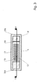
- einen Querschnitt durch das erfindungsgemässe Lüftungselement längs III-III in
Fig. 2 . - Die Lüftungseinrichtung umfasst ein quaderförmiges Gehäuse mit einem Boden 1, einer Decke 2, Seitenwänden 3a,b und Stirnwänden 4a,b. Das Innere des Gehäuses ist durch zwei zu den Stirnwänden 4a,b parallele Zwischenwände 5, 6 weiter unterteilt. Zwischen der ersten Zwischenwand 5 und der Stirnwand 4a liegt eine kurze Einlasskammer 7, welche durch einen schmalen rechteckigen Zulufteinlass 8 mit dem Aussenraum verbunden ist. In der Einlasskammer 8 sind als turbulenzerzeugende Einbauten zur Stirnwand 4b parallele Umlenkwände 9 eingebaut, welche sich jeweils über einen Teil des Querschnitts erstrecken. Zwischen der zweiten Zwischenwand 6 und der der Stirnwand 4a gegenüberliegenden Stirnwand 4b liegt eine kurze Auslasskammer 10, welche durch einen rechteckigen Zuluftauslass 11 in der Seitenwand 3a mit dem zu lüftenden Raum verbunden ist.
- Zwischen der ersten Zwischenwand 5 und der zweiten Zwischenwand 6 liegt ein längerer Hohlraum 12 rechteckigen Querschnitts. Seitlich voneinander beabstandete parallele Rohre 13, welche die Einlasskammer 8 mit der Auslasskammer 10 verbinden, sind durch die erste Zwischenwand 5 geführt, laufen, etwa gleichmässig über den Querschnitt verteilt, in Längsrichtung durch den Hohlraum 12 und durchdringen die zweite Zwischenwand 6. Auf der der Einlasskammer 8 abgewandten Seite weist die erste Zwischenwand 5 eine Isolationsschicht auf, so dass die Einlasskammer 8 vom Hohlraum 12 thermisch isoliert ist. Auch die Seitenwand 3b weist innen eine Isolationsschicht auf, welche die Einlasskammer 8, den Hohlraum 12 und die Auslasskammer 10 vom Aussenraum thermisch isoliert. Desgleichen weist in der Einlasskammer 8 die Seitenwand 3a innen eine Isolationsschicht auf, so dass die Einlasskammer 8 auch vom zu lüftenden Raum thermisch isoliert ist.
- Parallel zur Seitenwand 3a ist eine Trennwand 14 angeordnet, welche sich von der ersten Zwischenwand 5 gegen die zweite Zwischenwand 6 erstreckt, derart, dass dort ein rechteckiger Durchgang 15 zum Hohlraum 12 freibleibt. Anschliessend an die erste Zwischenwand 5 ist die Seitenwand 3a von einem rechteckigen Ablufteinlass 16 durchbrochen. Die gegenüberliegende Seitenwand 3b ist, ebenfalls anschliessend an die erste Zwischenwand 5, von einem rechteckigen Abluftauslass 17 durchbrochen, in welchem ein Ventilator 18 angebracht ist.
- Der Hohlraum 12 bildet mit den Rohren 13 einen Gegenstrom-Wärmetauscher mit einem Austauschabschnitt eines den Zulufteinlass 8 mit dem Zuluftauslass 11 verbindenenden Zuluftkanals, der durch den von den Rohren 13 umschlossenen Raum gebildet wird, während der verbleibende Teil des Hohlraums 12 einen Austauschabschnitt eines den Ablufteinlass 16 mit dem Abluftauslass 17 verbindenden Abluftkanals bildet. Die beiden Austauschabschnitte stehen durch die Rohre 13 hindurch in enger wärmeleitender Verbindung. Der zwischen der Seitenwand 3a und der Trennwand 14 liegende Bereich bildet einen den Ablufteinlass 16 mit dem Austauschabschnitt des Abluftkanals verbindenden Zuleitungsabschnitt 19 des letzteren, der, gegengleich zum Austauschabschnitt geführt, bis zum Durchgang 15 reicht.
- Der Zuleitungsabschnitt 19 ist durch mehrere - im Beispiel drei - in Längsrichtung versetzte Kurzschlussverbindungen mit dem Hohlraum 12 verbunden. Sie werden von als schmale Schlitze 20a,b,c ausgebildeten Durchlässen in der Trennwand 14 gebildet. Durch Vorsprünge an der Trennwand 14 sind jeweils unmittelbar vor den Schlitzen 20b,c Verengungen angelegt, so dass sich der Zuleitungsabschnitt 19 unmittelbar an den Schlitzen 20b,c erweitert. Am Schlitz 20a erweitert sich der Zuleitungsabschnitt 19 ebenfalls, da die Trennwand 14 bis zu diesem Durchlass eine den Zuleitungsabschnitt 19 vom Hohlraum 11 und damit vom Austauschabschnitt des Abluftkanals thermisch isolierende Isolationsschicht umfasst und daher dicker ist. Zwischen den Schlitzen 20a,b,c und am Durchgang 15 weist der Zuleitungsabschnitt 19 weitere Verengungen auf, die durch Vorsprünge an der Seitenwand 3a gebildet werden.
- Als Materialien für den Boden 1, den Deckel 2, die Seitenwände 3a,b, die Stirnwände 4a,b, die Zwischenwände 5, 6, die Umlenkwände 9 und die Trennwand 14 kommen Holz, Metall, Kunststoff, Pressspanplatten u.dgl. in Frage, wobei die Isolationsschichten aus Schaumstoff, z.B. Polyurethanschaumstoff bestehen können. Die Rohre 13 müssen aus gut wärmeleitendem Material bestehen. Hier bieten sich Metalle wie Aluminium, Stahl oder auch Kupfer an.
- Der Abluftstrom ist in den Figuren durch einen einfachen Pfeil dargestellt, der Zuluftstrom durch einen Doppelpfeil. Durch den Ventilator 18 wird Abluft aus dem zu lüftenden Raum durch den Abluftkanal gesaugt und ausgestossen. Durch die Anordnung des Ventilators 18 im Bereich des Abluftauslasses 17 wird Lärmbelastung des Raumes weitgehend vermieden. Die Abluft tritt durch den Ablufteinlass 16 in die Lüftungseinrichtung ein und fliesst durch den Zuleitungsabschnitt 19 und den Austauschabschnitt im Hohlraum 12 zum Abluftauslass 17. Durch den im zu lüftenden Raum erzeugten Unterdruck wird am Zulufteinlass 8 Zuluft angesaugt und durch den Zuluftkanal und den Zuluftauslass 11 in den Raum geleitet. Wegen Undichtigkeiten des Raumes ist der Zuluftstrom gewöhnlich geringer als der Abluftstrom.
- Ein Teil des Abluftstroms bleibt bis zum Durchgang 15, wo er um 180° umgelenkt wird und in den Hohlraum 12 übergeht, im Zuleitungsabschnitt 19, wo er vom Austauschabschnitt des Zuluftkanals thermisch isoliert ist. Andere Teile davon werden jedoch stromaufwärts des Durchgangs 15 durch die Schlitze 20a,b,c aus dem Zuleitungsabschnitt 19 abgezweigt und treten weiter stromabwärts in den Abluftstrom im Hohlraum 12, d.h. den Austauschabschnitt des Abluftkanals ein. Durch die Schlitze 20a,b,c werden daher Teile des Hohlraums 12 überbrückt, wobei die Eintrittsstelle der Kurzschlussverbindung umso weiter stromabwärts im Hohlraum 12 liegt, je weiter stromaufwärts ihre Abzweigstelle im Zuleitungsabschnitt 19 liegt. Der überbrückte Teil ist im Fall des Schlitzes 20c verhältnismässig kurz, beim Schlitz 20a beträgt er jedoch deutlich mehr als die Hälfte der Länge des Hohlraums 12.
- Die Schlitze 20a,b,c sind so dimensioniert, dass sie jeweils etwa 10-15% des gesamten Abluftstroms abzweigen, insgesamt beträgt der Anteil des Abluftstroms, der auf diese Weise einen kleineren oder grösseren Teil des Austauschabschnitts des Abluftkanals umgeht, ca. 25-50%. Es hat sich gezeigt, dass dieses Kurzschliessen von Teilen des Austauschabschnittes durch Teile des Abluftstromes den Wirkungsgrad der Lüftungseinrichtung in überraschender Weise verbessert.
- Es sind verschiedene Abwandlungen der beschriebenen Lüftungseinrichtung möglich. U.a. können die Rollen des Abluftkanals und des Zuluftkanals im wesentlichen vertauscht sein. Es ist auch möglich, im Zuluftkanal ebenfalls einen Ventilator vorzusehen. Ventilatoren sollten zwecks möglichst weitgehender Vermeidung von Lärm im zu lüftenden Raum womöglich immer am dem Aussenraum zugewandten Ende des Abluft- und gegebenenfalls des Zuluftkanals angeordnet sein.
-
- 1
- Boden
- 2
- Deckel
- 3a,b
- Seitenwände
- 4a,b
- Stirnwände
- 5
- erste Zwischenwand
- 6
- zweite Zwischenwand
- 7
- Einlasskammer
- 8
- Zulufteinlass
- 9
- Umlenkwände
- 10
- Auslasskammer
- 11
- Zuluftauslass
- 12
- Hohlraum
- 13
- Rohre
- 14
- Trennwand
- 15
- Durchgang
- 16
- Ablufteinlass
- 17
- Abluftauslass
- 18
- Ventilator
- 19
- Zuleitungsabschnitt
- 20a,b,c
- Durchlässe
Claims (18)
- Lüftungseinrichtung mit einem ersten Kanal, welcher einen ersten Einlass (16) mit einem ersten Auslass (17) verbindet und einem zweiten Kanal, welcher einen zweiten Einlass (8) mit einem zweiten Auslass (11) verbindet, wobei ein erster Austauschabschnitt, welcher einen Abschnitt des ersten Kanals bildet, und ein zweiter Austauschabschnitt, welcher einen Abschnitt des zweiten Kanals bildet, einen Wärmetauscher bilden, indem sie gegengleich in wärmeleitender Verbindung geführt sind, dadurch gekennzeichnet, dass der erste Einlass (16) mit mindestens einer stromabwärts des Anfangs des ersten Austauschabschnitts liegenden Eintrittsstelle über eine Kurzschlussverbindung verbunden ist, welche den zwischen dem Anfang und der Eintrittsstelle liegenden Teil des ersten Austauschabschnitts überbrückt.
- Lüftungseinrichtung nach Anspruch 1, dadurch gekennzeichnet, dass der erste Kanal einen den ersten Einlass mit dem Anfang des ersten Austauschabschnitts verbindenden Zuleitungsabschnitt (19) aufweist, von welchem die mindestens eine Kurzschlussverbindung an einer stromabwärts des ersten Einlasses liegenden Abzweigstelle abzweigt.
- Lüftungseinrichtung nach Anspruch 2, dadurch gekennzeichnet, dass sie mehrere Kurzschlussverbindungen aufweist, deren Eintrittsstellen stromabwärts versetzt im ersten Austauschabschnitt aufeinanderfolgen, während ihre Abzweigstellen stromaufwärts versetzt im Zuleitungsabschnitt (19) aufeinanderfolgen.
- Lüftungseinrichtung nach Anspruch 2 oder 3, dadurch gekennzeichnet, dass mindestens ein Teil des Zuleitungsabschnitts (19) gegengleich neben dem ersten Austauschabschnitt angeordnet ist.
- Lüftungseinrichtung nach Anspruch 4, dadurch gekennzeichnet, dass die Kurzschlussverbindung jeweils als Durchlass durch eine den Zuleitungsabschnitt (19) vom ersten Austauschabschnitt trennende Trennwand (14) ausgebildet ist.
- Lüftungseinrichtung nach Anspruch 5, dadurch gekennzeichnet, dass der Durchlass jeweils als Schlitz (20a, 20b, 20c) ausgebildet ist.
- Lüftungseinrichtung nach Anspruch 5 oder 6, dadurch gekennzeichnet, dass sich der Zuleitungsabschnitt (19) unmittelbar am Durchlass erweitert.
- Lüftungseinrichtung nach einem der Ansprüche 2 bis 7, dadurch gekennzeichnet, dass der Zuleitungsabschnitt (19) mehrere Verengungen aufweist.
- Lüftungseinrichtung nach einem der Ansprüche 2 bis 8, dadurch gekennzeichnet, dass mindestens ein allfälliger stromaufwärts der ersten Abzweigstelle liegender Teil des Zuleitungsabschnittes (19) vom Wärmetauscher thermisch isoliert ist.
- Lüftungseinrichtung nach einem der Ansprüche 1 bis 9, dadurch gekennzeichnet, dass der Wärmetauscher als länglicher Hohlraum (12) mit einer Mehrzahl in Längsrichtung denselben durchdringender Rohre (13) ausgebildet ist, deren Innenraum den zweiten Austauschabschnitt zubilden, während der verbleibende Teil des Hohlraums (12) den ersten Austauschabschnitt bildet.
- Lüftungseinrichtung nach Abschnitt 10, dadurch gekennzeichnet, dass die Rohre (13) parallel verlaufen.
- Lüftungseinrichtung nach Anspruche 10 oder 11, dadurch gekennzeichnet, dass die Rohre (13) mit dem zweiten Einlass über eine durch eine erste Zwischenwand (5), durch welche die Rohre (13) geführt sind, getrennte Einlasskammer (7) verbunden sind.
- Lüftungseinrichtung nach Anspruch 12, dadurch gekennzeichnet, dass die Einlasskammer (7) turbulenzerzeugende Einbauten aufweist.
- Lüftungseinrichtung nach Anspruch 12 oder 13, dadurch gekennzeichnet, dass die Einlasskammer (7) vom Hohlraum (12) thermisch isoliert ist.
- Lüftungseinrichtung nach einem der Ansprüche 10 bis 14, dadurch gekennzeichnet, dass die Rohre (13) mit dem zweiten Auslass über eine vom Hohlraum (12) durch eine zweite Zwischenwand (6), durch welche die Rohre (13) geführt sind, getrennte Auslasskammer (10) verbunden sind.
- Lüftungseinrichtung nach einem der Ansprüche 12 bis 15, dadurch gekennzeichnet, dass der erste Einlass und der erste Auslass unmittelbar an der ersten Zwischenwand (5) angeordnet sind.
- Lüftungseinrichtung nach einem der Ansprüche 1 bis 16, dadurch gekennzeichnet, dass im Bereich des ersten Auslasses ein Ventilator (18) angeordnet ist.
- Verfahren zum Betrieb der Lüftungseinrichtung nach einem der Ansprüche 1 bis 17 zur Lüftung eines geheizten oder gekühlten Raumes, dadurch gekennzeichnet, dass der erste Kanal als Abluftkanal eingesetzt wird mit dem ersten Einlass als im Raum angeordnetem Ablufteinlass (16) und dem ersten Auslass als ausserhalb des Raumes angeordnetem Abluftauslass (17) und der zweite Kanal als Zuluftkanal mit dem zweiten Einlass als ausserhalb des Raumes angeordnetem Zulufteinlass (8) und dem zweiten Auslass als im Raum angeordnetem Zuluftauslass (11).
Priority Applications (5)
| Application Number | Priority Date | Filing Date | Title |
|---|---|---|---|
| DK03405618.4T DK1510764T3 (da) | 2003-08-27 | 2003-08-27 | Ventilationsindretning og fremgangsmåde til drift heraf |
| DE50313546T DE50313546D1 (de) | 2003-08-27 | 2003-08-27 | Lüftungseinrichtung und Verfahren zu ihrem Betrieb |
| AT03405618T ATE502265T1 (de) | 2003-08-27 | 2003-08-27 | Lüftungseinrichtung und verfahren zu ihrem betrieb |
| EP03405618A EP1510764B1 (de) | 2003-08-27 | 2003-08-27 | Lüftungseinrichtung und Verfahren zu ihrem Betrieb |
| US10/927,896 US20050103483A1 (en) | 2003-08-27 | 2004-08-27 | Ventilation device and method for its operation |
Applications Claiming Priority (1)
| Application Number | Priority Date | Filing Date | Title |
|---|---|---|---|
| EP03405618A EP1510764B1 (de) | 2003-08-27 | 2003-08-27 | Lüftungseinrichtung und Verfahren zu ihrem Betrieb |
Publications (2)
| Publication Number | Publication Date |
|---|---|
| EP1510764A1 EP1510764A1 (de) | 2005-03-02 |
| EP1510764B1 true EP1510764B1 (de) | 2011-03-16 |
Family
ID=34089786
Family Applications (1)
| Application Number | Title | Priority Date | Filing Date |
|---|---|---|---|
| EP03405618A Expired - Lifetime EP1510764B1 (de) | 2003-08-27 | 2003-08-27 | Lüftungseinrichtung und Verfahren zu ihrem Betrieb |
Country Status (5)
| Country | Link |
|---|---|
| US (1) | US20050103483A1 (de) |
| EP (1) | EP1510764B1 (de) |
| AT (1) | ATE502265T1 (de) |
| DE (1) | DE50313546D1 (de) |
| DK (1) | DK1510764T3 (de) |
Families Citing this family (3)
| Publication number | Priority date | Publication date | Assignee | Title |
|---|---|---|---|---|
| US20080271874A1 (en) * | 2007-05-04 | 2008-11-06 | John Gietzen | Thermal energy exchanger |
| GB2452927B (en) * | 2007-09-18 | 2012-09-19 | Vent Axia Group Ltd | A heat recovery ventilation device |
| FR2931931B1 (fr) * | 2008-05-29 | 2010-12-17 | Pierre Vironneau | Dispositif echangeur de chaleur double flux. |
Citations (3)
| Publication number | Priority date | Publication date | Assignee | Title |
|---|---|---|---|---|
| GB678342A (en) * | 1949-09-26 | 1952-09-03 | Sulzer Ag | Improvements relating to heat exchangers |
| JPS62206381A (ja) * | 1986-03-06 | 1987-09-10 | Nippon Furuuto Kk | 熱交換装置 |
| DE3643303A1 (de) * | 1986-12-18 | 1988-06-30 | Uhde Gmbh | Vorrichtung zum waermetausch, insbesondere zwischen synthesegas- und kesselspeisewasser |
Family Cites Families (10)
| Publication number | Priority date | Publication date | Assignee | Title |
|---|---|---|---|---|
| DE853202C (de) * | 1949-07-30 | 1952-10-23 | Hans Studer | Zur Rueckgewinnung von Waerme aus der Abluft zur Vorwaermung der Frischluft geeignete Einrichtung zur Raumlueftung |
| CH519150A (de) * | 1970-07-17 | 1972-02-15 | Bbc Sulzer Turbomaschinen | Wärmeaustauscher mit kreiszylindrischem Gehäuse |
| DE2842974A1 (de) * | 1978-10-02 | 1980-04-10 | Hermann Dieterichs | Vorrichtung fuer die klimatisierung von raeumen mit entsprechendem luftwechsel, insbesondere bei gefluegel-maststaellen |
| DE3230279A1 (de) | 1982-08-14 | 1984-02-16 | Fulgurit Gmbh & Co Kg | Vorrichtung zur raumbelueftung |
| CA1176236A (en) * | 1983-03-29 | 1984-10-16 | Jonathan P. Maendel | Heat exchanger |
| DE3347028A1 (de) | 1983-12-24 | 1985-07-04 | Greschbach Industrie GmbH & Co, 7834 Herbolzheim | Fenster |
| DE3426778A1 (de) | 1984-07-20 | 1985-05-02 | Werner G.K. 2000 Hamburg Lange | Vorrichtung zum austausch von waerme-energie zwischen luftstroemen zur rueckgewinnung von lueftungswaerme |
| US4722683A (en) * | 1986-03-14 | 1988-02-02 | Vulcan-Hart Corporation | Rethermalization oven |
| GB9420731D0 (en) | 1994-10-14 | 1994-11-30 | Stokes Keith H | An improved heat exchange ventilator |
| ATE397193T1 (de) | 2001-11-01 | 2008-06-15 | Albisrieden Fenster | Lüftungseinrichtung |
-
2003
- 2003-08-27 EP EP03405618A patent/EP1510764B1/de not_active Expired - Lifetime
- 2003-08-27 DE DE50313546T patent/DE50313546D1/de not_active Expired - Lifetime
- 2003-08-27 DK DK03405618.4T patent/DK1510764T3/da active
- 2003-08-27 AT AT03405618T patent/ATE502265T1/de active
-
2004
- 2004-08-27 US US10/927,896 patent/US20050103483A1/en not_active Abandoned
Patent Citations (3)
| Publication number | Priority date | Publication date | Assignee | Title |
|---|---|---|---|---|
| GB678342A (en) * | 1949-09-26 | 1952-09-03 | Sulzer Ag | Improvements relating to heat exchangers |
| JPS62206381A (ja) * | 1986-03-06 | 1987-09-10 | Nippon Furuuto Kk | 熱交換装置 |
| DE3643303A1 (de) * | 1986-12-18 | 1988-06-30 | Uhde Gmbh | Vorrichtung zum waermetausch, insbesondere zwischen synthesegas- und kesselspeisewasser |
Also Published As
| Publication number | Publication date |
|---|---|
| DE50313546D1 (de) | 2011-04-28 |
| DK1510764T3 (da) | 2011-07-04 |
| ATE502265T1 (de) | 2011-04-15 |
| EP1510764A1 (de) | 2005-03-02 |
| US20050103483A1 (en) | 2005-05-19 |
Similar Documents
| Publication | Publication Date | Title |
|---|---|---|
| DE102016006531A1 (de) | Kühleraggregat für ein Kraftfahrzeug | |
| EP4067753B1 (de) | Anordnung umfassend eine downdraft-dunstabzugshaube und eine flachkanalanordnung | |
| DE102020131023A1 (de) | Fluidführungselement und Fluidheizer | |
| EP2192367B1 (de) | Wärmeaustauscher | |
| EP4232758B1 (de) | Lüftungsvorrichtung | |
| EP1308678B1 (de) | Lüftungseinrichtung | |
| EP3285017B1 (de) | Heiz- und kühlsegel mit mindestens einem ventilator | |
| EP1510764A1 (de) | Lüftungseinrichtung und Verfahren zu ihrem Betrieb | |
| DE10109753A1 (de) | Lüftungsgerät für die Gebäudelüftung | |
| DE9200134U1 (de) | Kühlgerät für Schaltschränke | |
| WO2006042425A1 (de) | Lüftungseinrichtung und verfahren zu ihrem betrieb | |
| EP3507559A1 (de) | Wärmetauscherintegration | |
| CH657693A5 (de) | Lueftungsvorrichtung fuer einen raum mit zwei getrennten stroemungswegen zur belueftung und entlueftung. | |
| DE1501577A1 (de) | Waermeaustauscher | |
| DE3905092C2 (de) | ||
| EP4177557B1 (de) | Wärmeübertragungsvorrichtung | |
| DE102006022088B4 (de) | Klimaanlage für ein Fahrzeug und Luftmischvorrichtung | |
| DE3911515C2 (de) | ||
| DE102016116276A1 (de) | Wärmetauscherintegration | |
| EP2080910B1 (de) | Gebläse, insbesondere Fahrzeuggebläse | |
| DE202016104805U1 (de) | Wärmetauscherintegration | |
| EP2650618B1 (de) | Dezentrales Lüftungsgerät | |
| DE102008052823B4 (de) | Querstromventilator, Lüftungsgerät mit Querstromventilator und Verfahren zur Lüftung eines Raumes mittels eines Querstromventilators | |
| DE202016105442U1 (de) | Wärmetauscherintegration | |
| DE102016015760A1 (de) | Wärmetauscherintegration |
Legal Events
| Date | Code | Title | Description |
|---|---|---|---|
| PUAI | Public reference made under article 153(3) epc to a published international application that has entered the european phase |
Free format text: ORIGINAL CODE: 0009012 |
|
| AK | Designated contracting states |
Kind code of ref document: A1 Designated state(s): AT BE BG CH CY CZ DE DK EE ES FI FR GB GR HU IE IT LI LU MC NL PT RO SE SI SK TR |
|
| AX | Request for extension of the european patent |
Extension state: AL LT LV MK |
|
| 17P | Request for examination filed |
Effective date: 20050819 |
|
| AKX | Designation fees paid |
Designated state(s): AT BE BG CH CY CZ DE DK EE ES FI FR GB GR HU IE IT LI LU MC NL PT RO SE SI SK TR |
|
| 17Q | First examination report despatched |
Effective date: 20060509 |
|
| GRAP | Despatch of communication of intention to grant a patent |
Free format text: ORIGINAL CODE: EPIDOSNIGR1 |
|
| GRAC | Information related to communication of intention to grant a patent modified |
Free format text: ORIGINAL CODE: EPIDOSCIGR1 |
|
| GRAC | Information related to communication of intention to grant a patent modified |
Free format text: ORIGINAL CODE: EPIDOSCIGR1 |
|
| GRAS | Grant fee paid |
Free format text: ORIGINAL CODE: EPIDOSNIGR3 |
|
| GRAA | (expected) grant |
Free format text: ORIGINAL CODE: 0009210 |
|
| AK | Designated contracting states |
Kind code of ref document: B1 Designated state(s): AT BE BG CH CY CZ DE DK EE ES FI FR GB GR HU IE IT LI LU MC NL PT RO SE SI SK TR |
|
| REG | Reference to a national code |
Ref country code: GB Ref legal event code: FG4D Free format text: NOT ENGLISH |
|
| REG | Reference to a national code |
Ref country code: CH Ref legal event code: EP |
|
| REG | Reference to a national code |
Ref country code: IE Ref legal event code: FG4D |
|
| REF | Corresponds to: |
Ref document number: 50313546 Country of ref document: DE Date of ref document: 20110428 Kind code of ref document: P |
|
| REG | Reference to a national code |
Ref country code: DE Ref legal event code: R096 Ref document number: 50313546 Country of ref document: DE Effective date: 20110428 |
|
| REG | Reference to a national code |
Ref country code: CH Ref legal event code: NV Representative=s name: ZIMMERLI, WAGNER & PARTNER AG |
|
| REG | Reference to a national code |
Ref country code: DK Ref legal event code: T3 |
|
| REG | Reference to a national code |
Ref country code: NL Ref legal event code: VDEP Effective date: 20110316 |
|
| PG25 | Lapsed in a contracting state [announced via postgrant information from national office to epo] |
Ref country code: ES Free format text: LAPSE BECAUSE OF FAILURE TO SUBMIT A TRANSLATION OF THE DESCRIPTION OR TO PAY THE FEE WITHIN THE PRESCRIBED TIME-LIMIT Effective date: 20110627 Ref country code: GR Free format text: LAPSE BECAUSE OF FAILURE TO SUBMIT A TRANSLATION OF THE DESCRIPTION OR TO PAY THE FEE WITHIN THE PRESCRIBED TIME-LIMIT Effective date: 20110617 Ref country code: SE Free format text: LAPSE BECAUSE OF FAILURE TO SUBMIT A TRANSLATION OF THE DESCRIPTION OR TO PAY THE FEE WITHIN THE PRESCRIBED TIME-LIMIT Effective date: 20110316 |
|
| PG25 | Lapsed in a contracting state [announced via postgrant information from national office to epo] |
Ref country code: SI Free format text: LAPSE BECAUSE OF FAILURE TO SUBMIT A TRANSLATION OF THE DESCRIPTION OR TO PAY THE FEE WITHIN THE PRESCRIBED TIME-LIMIT Effective date: 20110316 Ref country code: BG Free format text: LAPSE BECAUSE OF FAILURE TO SUBMIT A TRANSLATION OF THE DESCRIPTION OR TO PAY THE FEE WITHIN THE PRESCRIBED TIME-LIMIT Effective date: 20110616 Ref country code: CY Free format text: LAPSE BECAUSE OF FAILURE TO SUBMIT A TRANSLATION OF THE DESCRIPTION OR TO PAY THE FEE WITHIN THE PRESCRIBED TIME-LIMIT Effective date: 20110316 Ref country code: FI Free format text: LAPSE BECAUSE OF FAILURE TO SUBMIT A TRANSLATION OF THE DESCRIPTION OR TO PAY THE FEE WITHIN THE PRESCRIBED TIME-LIMIT Effective date: 20110316 |
|
| REG | Reference to a national code |
Ref country code: IE Ref legal event code: FD4D |
|
| PG25 | Lapsed in a contracting state [announced via postgrant information from national office to epo] |
Ref country code: EE Free format text: LAPSE BECAUSE OF FAILURE TO SUBMIT A TRANSLATION OF THE DESCRIPTION OR TO PAY THE FEE WITHIN THE PRESCRIBED TIME-LIMIT Effective date: 20110316 Ref country code: IE Free format text: LAPSE BECAUSE OF FAILURE TO SUBMIT A TRANSLATION OF THE DESCRIPTION OR TO PAY THE FEE WITHIN THE PRESCRIBED TIME-LIMIT Effective date: 20110316 Ref country code: PT Free format text: LAPSE BECAUSE OF FAILURE TO SUBMIT A TRANSLATION OF THE DESCRIPTION OR TO PAY THE FEE WITHIN THE PRESCRIBED TIME-LIMIT Effective date: 20110718 |
|
| PG25 | Lapsed in a contracting state [announced via postgrant information from national office to epo] |
Ref country code: CZ Free format text: LAPSE BECAUSE OF FAILURE TO SUBMIT A TRANSLATION OF THE DESCRIPTION OR TO PAY THE FEE WITHIN THE PRESCRIBED TIME-LIMIT Effective date: 20110316 Ref country code: RO Free format text: LAPSE BECAUSE OF FAILURE TO SUBMIT A TRANSLATION OF THE DESCRIPTION OR TO PAY THE FEE WITHIN THE PRESCRIBED TIME-LIMIT Effective date: 20110316 Ref country code: SK Free format text: LAPSE BECAUSE OF FAILURE TO SUBMIT A TRANSLATION OF THE DESCRIPTION OR TO PAY THE FEE WITHIN THE PRESCRIBED TIME-LIMIT Effective date: 20110316 |
|
| PG25 | Lapsed in a contracting state [announced via postgrant information from national office to epo] |
Ref country code: NL Free format text: LAPSE BECAUSE OF FAILURE TO SUBMIT A TRANSLATION OF THE DESCRIPTION OR TO PAY THE FEE WITHIN THE PRESCRIBED TIME-LIMIT Effective date: 20110316 |
|
| PGFP | Annual fee paid to national office [announced via postgrant information from national office to epo] |
Ref country code: BE Payment date: 20110812 Year of fee payment: 9 |
|
| PLBE | No opposition filed within time limit |
Free format text: ORIGINAL CODE: 0009261 |
|
| STAA | Information on the status of an ep patent application or granted ep patent |
Free format text: STATUS: NO OPPOSITION FILED WITHIN TIME LIMIT |
|
| 26N | No opposition filed |
Effective date: 20111219 |
|
| PG25 | Lapsed in a contracting state [announced via postgrant information from national office to epo] |
Ref country code: MC Free format text: LAPSE BECAUSE OF NON-PAYMENT OF DUE FEES Effective date: 20110831 |
|
| REG | Reference to a national code |
Ref country code: DE Ref legal event code: R097 Ref document number: 50313546 Country of ref document: DE Effective date: 20111219 |
|
| GBPC | Gb: european patent ceased through non-payment of renewal fee |
Effective date: 20110827 |
|
| REG | Reference to a national code |
Ref country code: FR Ref legal event code: ST Effective date: 20120430 |
|
| PG25 | Lapsed in a contracting state [announced via postgrant information from national office to epo] |
Ref country code: IT Free format text: LAPSE BECAUSE OF FAILURE TO SUBMIT A TRANSLATION OF THE DESCRIPTION OR TO PAY THE FEE WITHIN THE PRESCRIBED TIME-LIMIT Effective date: 20110316 |
|
| PG25 | Lapsed in a contracting state [announced via postgrant information from national office to epo] |
Ref country code: GB Free format text: LAPSE BECAUSE OF NON-PAYMENT OF DUE FEES Effective date: 20110827 Ref country code: FR Free format text: LAPSE BECAUSE OF NON-PAYMENT OF DUE FEES Effective date: 20110831 |
|
| BERE | Be: lapsed |
Owner name: FENSTERFABRIK ALBISRIEDEN A.G. Effective date: 20120831 |
|
| PG25 | Lapsed in a contracting state [announced via postgrant information from national office to epo] |
Ref country code: BE Free format text: LAPSE BECAUSE OF NON-PAYMENT OF DUE FEES Effective date: 20120831 Ref country code: LU Free format text: LAPSE BECAUSE OF NON-PAYMENT OF DUE FEES Effective date: 20110827 |
|
| PG25 | Lapsed in a contracting state [announced via postgrant information from national office to epo] |
Ref country code: TR Free format text: LAPSE BECAUSE OF FAILURE TO SUBMIT A TRANSLATION OF THE DESCRIPTION OR TO PAY THE FEE WITHIN THE PRESCRIBED TIME-LIMIT Effective date: 20110316 |
|
| PG25 | Lapsed in a contracting state [announced via postgrant information from national office to epo] |
Ref country code: HU Free format text: LAPSE BECAUSE OF FAILURE TO SUBMIT A TRANSLATION OF THE DESCRIPTION OR TO PAY THE FEE WITHIN THE PRESCRIBED TIME-LIMIT Effective date: 20110316 |
|
| PGFP | Annual fee paid to national office [announced via postgrant information from national office to epo] |
Ref country code: AT Payment date: 20130813 Year of fee payment: 11 |
|
| REG | Reference to a national code |
Ref country code: CH Ref legal event code: NV Representative=s name: WAGNER PATENT AG, CH |
|
| REG | Reference to a national code |
Ref country code: AT Ref legal event code: MM01 Ref document number: 502265 Country of ref document: AT Kind code of ref document: T Effective date: 20140827 |
|
| PG25 | Lapsed in a contracting state [announced via postgrant information from national office to epo] |
Ref country code: AT Free format text: LAPSE BECAUSE OF NON-PAYMENT OF DUE FEES Effective date: 20140827 |
|
| PGFP | Annual fee paid to national office [announced via postgrant information from national office to epo] |
Ref country code: DK Payment date: 20160819 Year of fee payment: 14 |
|
| PGFP | Annual fee paid to national office [announced via postgrant information from national office to epo] |
Ref country code: DE Payment date: 20170822 Year of fee payment: 15 |
|
| REG | Reference to a national code |
Ref country code: DK Ref legal event code: EBP Effective date: 20170831 |
|
| PG25 | Lapsed in a contracting state [announced via postgrant information from national office to epo] |
Ref country code: DK Free format text: LAPSE BECAUSE OF NON-PAYMENT OF DUE FEES Effective date: 20170831 |
|
| REG | Reference to a national code |
Ref country code: DE Ref legal event code: R119 Ref document number: 50313546 Country of ref document: DE |
|
| PG25 | Lapsed in a contracting state [announced via postgrant information from national office to epo] |
Ref country code: DE Free format text: LAPSE BECAUSE OF NON-PAYMENT OF DUE FEES Effective date: 20190301 |
|
| PGFP | Annual fee paid to national office [announced via postgrant information from national office to epo] |
Ref country code: CH Payment date: 20220915 Year of fee payment: 20 |
|
| REG | Reference to a national code |
Ref country code: CH Ref legal event code: PL |