EP2075615A1 - Microscope - Google Patents
Microscope Download PDFInfo
- Publication number
- EP2075615A1 EP2075615A1 EP07830139A EP07830139A EP2075615A1 EP 2075615 A1 EP2075615 A1 EP 2075615A1 EP 07830139 A EP07830139 A EP 07830139A EP 07830139 A EP07830139 A EP 07830139A EP 2075615 A1 EP2075615 A1 EP 2075615A1
- Authority
- EP
- European Patent Office
- Prior art keywords
- light source
- lens
- optical system
- fly
- pupil
- Prior art date
- Legal status (The legal status is an assumption and is not a legal conclusion. Google has not performed a legal analysis and makes no representation as to the accuracy of the status listed.)
- Granted
Links
- 230000003287 optical effect Effects 0.000 claims abstract description 398
- 238000005286 illumination Methods 0.000 claims abstract description 265
- 210000001747 pupil Anatomy 0.000 claims abstract description 219
- 238000003384 imaging method Methods 0.000 claims abstract description 200
- 230000005284 excitation Effects 0.000 claims description 82
- 230000004888 barrier function Effects 0.000 claims description 61
- 239000000835 fiber Substances 0.000 claims description 51
- 230000015572 biosynthetic process Effects 0.000 claims description 50
- 238000006243 chemical reaction Methods 0.000 claims description 34
- 238000003780 insertion Methods 0.000 claims description 14
- 230000037431 insertion Effects 0.000 claims description 14
- 230000007246 mechanism Effects 0.000 claims description 11
- 238000012937 correction Methods 0.000 claims description 9
- 230000000007 visual effect Effects 0.000 claims description 7
- 230000000903 blocking effect Effects 0.000 claims description 6
- 239000013307 optical fiber Substances 0.000 description 25
- 230000000694 effects Effects 0.000 description 15
- QSHDDOUJBYECFT-UHFFFAOYSA-N mercury Chemical compound [Hg] QSHDDOUJBYECFT-UHFFFAOYSA-N 0.000 description 10
- 229910052753 mercury Inorganic materials 0.000 description 10
- 239000011521 glass Substances 0.000 description 8
- 230000003902 lesion Effects 0.000 description 7
- 229910001507 metal halide Inorganic materials 0.000 description 7
- 150000005309 metal halides Chemical class 0.000 description 7
- 238000011002 quantification Methods 0.000 description 7
- 238000000034 method Methods 0.000 description 6
- 230000008859 change Effects 0.000 description 5
- 239000003086 colorant Substances 0.000 description 4
- 239000003814 drug Substances 0.000 description 4
- 239000007788 liquid Substances 0.000 description 4
- 238000002834 transmittance Methods 0.000 description 4
- 238000004061 bleaching Methods 0.000 description 3
- 230000001771 impaired effect Effects 0.000 description 3
- 230000001678 irradiating effect Effects 0.000 description 3
- 230000031700 light absorption Effects 0.000 description 3
- 238000005452 bending Methods 0.000 description 2
- 239000000470 constituent Substances 0.000 description 2
- 238000001514 detection method Methods 0.000 description 2
- 230000002349 favourable effect Effects 0.000 description 2
- 239000000463 material Substances 0.000 description 2
- 230000011514 reflex Effects 0.000 description 2
- 230000003595 spectral effect Effects 0.000 description 2
- 235000010627 Phaseolus vulgaris Nutrition 0.000 description 1
- 244000046052 Phaseolus vulgaris Species 0.000 description 1
- 230000005540 biological transmission Effects 0.000 description 1
- 238000013461 design Methods 0.000 description 1
Images


Classifications
-
- G—PHYSICS
- G01—MEASURING; TESTING
- G01N—INVESTIGATING OR ANALYSING MATERIALS BY DETERMINING THEIR CHEMICAL OR PHYSICAL PROPERTIES
- G01N21/00—Investigating or analysing materials by the use of optical means, i.e. using sub-millimetre waves, infrared, visible or ultraviolet light
- G01N21/62—Systems in which the material investigated is excited whereby it emits light or causes a change in wavelength of the incident light
- G01N21/63—Systems in which the material investigated is excited whereby it emits light or causes a change in wavelength of the incident light optically excited
- G01N21/64—Fluorescence; Phosphorescence
- G01N21/645—Specially adapted constructive features of fluorimeters
- G01N21/6456—Spatial resolved fluorescence measurements; Imaging
- G01N21/6458—Fluorescence microscopy
-
- G—PHYSICS
- G02—OPTICS
- G02B—OPTICAL ELEMENTS, SYSTEMS OR APPARATUS
- G02B13/00—Optical objectives specially designed for the purposes specified below
- G02B13/0095—Relay lenses or rod lenses
-
- G—PHYSICS
- G02—OPTICS
- G02B—OPTICAL ELEMENTS, SYSTEMS OR APPARATUS
- G02B21/00—Microscopes
- G02B21/06—Means for illuminating specimens
- G02B21/08—Condensers
- G02B21/082—Condensers for incident illumination only
-
- G—PHYSICS
- G02—OPTICS
- G02B—OPTICAL ELEMENTS, SYSTEMS OR APPARATUS
- G02B21/00—Microscopes
- G02B21/16—Microscopes adapted for ultraviolet illumination ; Fluorescence microscopes
-
- G—PHYSICS
- G02—OPTICS
- G02B—OPTICAL ELEMENTS, SYSTEMS OR APPARATUS
- G02B21/00—Microscopes
- G02B21/36—Microscopes arranged for photographic purposes or projection purposes or digital imaging or video purposes including associated control and data processing arrangements
- G02B21/361—Optical details, e.g. image relay to the camera or image sensor
-
- G—PHYSICS
- G02—OPTICS
- G02B—OPTICAL ELEMENTS, SYSTEMS OR APPARATUS
- G02B21/00—Microscopes
- G02B21/0004—Microscopes specially adapted for specific applications
- G02B21/002—Scanning microscopes
- G02B21/0024—Confocal scanning microscopes (CSOMs) or confocal "macroscopes"; Accessories which are not restricted to use with CSOMs, e.g. sample holders
- G02B21/0032—Optical details of illumination, e.g. light-sources, pinholes, beam splitters, slits, fibers
-
- G—PHYSICS
- G02—OPTICS
- G02B—OPTICAL ELEMENTS, SYSTEMS OR APPARATUS
- G02B21/00—Microscopes
- G02B21/0004—Microscopes specially adapted for specific applications
- G02B21/002—Scanning microscopes
- G02B21/0024—Confocal scanning microscopes (CSOMs) or confocal "macroscopes"; Accessories which are not restricted to use with CSOMs, e.g. sample holders
- G02B21/0052—Optical details of the image generation
- G02B21/0076—Optical details of the image generation arrangements using fluorescence or luminescence
-
- G—PHYSICS
- G02—OPTICS
- G02B—OPTICAL ELEMENTS, SYSTEMS OR APPARATUS
- G02B21/00—Microscopes
- G02B21/36—Microscopes arranged for photographic purposes or projection purposes or digital imaging or video purposes including associated control and data processing arrangements
- G02B21/365—Control or image processing arrangements for digital or video microscopes
- G02B21/367—Control or image processing arrangements for digital or video microscopes providing an output produced by processing a plurality of individual source images, e.g. image tiling, montage, composite images, depth sectioning, image comparison
Definitions
- This invention relates to a microscope in which an image of a specimen is formed and observed.
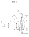
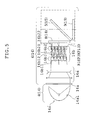
- Fig. 1 is a conceptual view showing an example of a fundamental optical arrangement of a conventional microscope of this type. Also, for convenience of comparison with the present invention to be described later, the figure is upside down.
- the microscope shown in Fig. 1 has an objective lens 51, an imaging lens 52, an image sensor 53, an illumination light source 54, and a reflecting fluorescence illumination optical system 56.
- reference symbol P denotes the pupil position of the objective lens 51 and O denotes the center axis of the objective lens 51 and the imaging lens 52.
- the imaging lens 52 is designed to project light passing through the objective lens 51 and to form the image of a specimen 57.
- the image sensor 53 is located at the position where the image of the specimen 57 is formed by the imaging lens 52.
- the reflecting fluorescence illumination optical system 56 is constructed to have a dichroic mirror 55 introducing light from the illumination light source 54 into an optical path on the objective-lens-51 side and to illuminate the specimen 57 with the light.
- a desired optical member is inserted in the optical path between the objective lens 51 and the imaging lend 52 in accordance with an observation application.
- an arrangement for a fluorescence observation is shown, and an excitation filter 58 and a barrier filter 59 are arranged on the illumination-light-source-54 side of the dichroic mirror 55 and on the specimen-57 side, respectively.
- Light in which unwanted wavelength other than desired fluorescent light is cut off through the barrier filter 59 is incident on the imaging lens 52 and is formed as the image of the specimen 57 on the image pickup surface of the image sensor 53 through the imaging lens 52 so that the image is picked up by the image sensor 53.
- the image of the specimen 57 picked up by the image sensor 53 can be observed as a picture through a display device omitted from the figure.
- a conventional microscope of such a type is set forth, for example, in Japanese Patent Kokai No. 2000-98244 .
- the light traveling through the periphery is eclipsed and ceases to be incident on the barrier filter 59 and the imaging lens 52, and the amount of light imaged on the periphery of the image pickup surface of the image sensor 53 becomes smaller than that at the center.
- the dichroic mirror 55 is located at a distance away from the pupil position P of the objective lens 51 and a pupil position conjugate with the pupil position P, and hence a marginal beam passing through the dichroic mirror 55 considerably deviates from a central beam.
- a cube provided with the excitation filter 58 and the barrier filter 59 in the proximity of the dichroic mirror 55 is often used, as a unit, to be movable in and out of the optical path.
- the optical system is designed so that, in addition to the unit mentioned above, for example, various optical members, such as pupil modulation means, can be located to be movable to and out of preset positions in the optical path according to the observation application.
- various optical members such as pupil modulation means
- the dichroic mirror 55 is located at a distance away from the pupil position P of the objective lens 51 and the conjugate pupil position.
- each of the pupil modulation means such as a variable stop, a phase plate, and a Nomarski prism, cannot be placed in the proximity of the dichroic mirror 55.
- the objective lens must be exchanged with an objective lens having the pupil position according to each of the pupil modulation means. This leads to the complication of operation.
- an object of the present invention to provide a microscope in which the amount of light for forming an image in the image pickup area and the amount of light for illumination in the observation region can be equalized and the amount of light is efficiently utilized to be switchable to various observations.
- the microscope according to the present invention has an objective lens, an imaging lens projecting light passing through the objective lens to form an image of a specimen, an image sensor located at an imaging position where the image of the specimen is formed by the imaging lens, an illumination light source, and a reflecting fluorescence illumination optical system including a dichroic mirror introducing light from the illumination light source into an optical path on the objective lens side, illuminating the specimen with the light.
- the microscope further has a relay optical system in which an intermediate image of the specimen is formed between the objective lens and the imaging lens and is relayed to the imaging lens, and the dichroic mirror of the reflecting fluorescence illumination optical system is located between a pupil position conjugate with a pupil position of the objective lens, formed between the relay optical system and the imaging lens, and the relay optical system.
- the dichroic mirror of the reflecting fluorescence illumination optical system is located on the proximity of the pupil position conjugate with the pupil position of the objective lens, formed between the relay optical system and the imaging lens.
- a light beam from the specimen is nearly afocal at the pupil position conjugate with the pupil position of the objective lens, formed between the relay optical system and the imaging lens.
- the imaging lens is constructed with an imaging optical system provided with a zoom optical system or a variable magnification optical system whose magnification is changed stepwise.
- ⁇ is a pupil relay magnification of the relay optical system from a pupil of the objective lens to a pupil conjugate position.
- a fly-eye lens is placed in the proximity of a pupil position in the reflecting fluorescence illumination optical system, conjugate with the pupil position of the objective lens.
- the illumination light source is constructed with a reflector light source, an LED light source, or a fiber light source.
- the illumination light source is constructed with the reflector light source;
- the reflecting fluorescence illumination optical system has a beam conversion optical system carrying out a preset conversion with respect to a light beam emitted from the reflector light source to make a parallel beam emerge therefrom and the fly-eye lens;
- the fly-eye lens includes a lens array whose entrance end faces are provided with a plurality of convex surfaces and a lens array whose exit end faces are provided with a plurality of convex surfaces, integrally or separately constructed, so that the parallel beam emerging from the beam conversion optical system is split into a plurality of beams and a plurality of light source images of the reflector light source are formed in the proximity of the exit end faces.
- the reflector light source is constructed so that a convergent beam is emitted to perform a primary formation of a light source image
- the beam conversion optical system is constructed with a collector lens converting a light beam diverging from the position of the primary formation into a parallel beam.
- the reflector light source is constructed so that a parallel beam is emitted and the beam conversion optical system is constructed with an afocal system converting the diameter of the parallel beam emitted from the reflector light source so as to become nearly equal to the diameter of the fly-eye lens.
- the afocal system is constructed so that the parallel beam emitted from the reflector light source is condensed and after the primary formation of the light source image of the reflector light source is performed inside the system, a condensed beam is converted into a parallel beam to emerge therefrom.
- the illumination light source has a reflector light source emitting a convergent beam to perform a primary formation of a light source image and a fiber having an entrance end face at a position of the primary formation;
- the reflecting fluorescence illumination optical system has a collector lens converting a divergent beam emerging from an exit end face of the fiber into a parallel beam and the fly-eye lens;
- the fly-eye lens has a lens array whose entrance end faces are provided with a plurality of convex surfaces and a lens array whose exit end faces are provided with a plurality of convex surfaces, integrally or separately constructed, so that the parallel beam emerging from the collector lens is split into a plurality of beams and a plurality of light source images of the illumination light source are formed in the proximity of the exit end faces.
- the illumination light source has a reflector light source emitting a parallel beam, a lens condensing the parallel beam emitted from the reflector light source to perform a primary formation of a light source image of the reflector light source, and a fiber having an entrance end face at a position of the primary formation;
- the reflecting fluorescence illumination optical system has a collector lens converting a divergent beam emerging from an exit end face of the fiber into a parallel beam and the fly-eye lens;
- the fly-eye lens has a lens array whose entrance end faces are provided with a plurality of convex surfaces and a lens array whose exit end faces are provided with a plurality of convex surfaces, integrally or separately constructed, so that the parallel beam emerging from the collector lens is split into a plurality of beams and a plurality of light source images of the illumination light source are formed in the proximity of the exit end faces.
- the illumination light source has a reflector light source emitting a convergent beam to perform a primary formation of a light source image and an integrator rod having an entrance end face at a position of the primary formation;
- the reflecting fluorescence illumination optical system has a collector lens converting a divergent beam emerging from an exit end face of the integrator rod into a parallel beam and the fly-eye lens;
- the fly-eye lens includes a lens array whose entrance end faces are provided with a plurality of convex surfaces and a lens array whose exit end faces are provided with a plurality of convex surfaces, integrally or separately constructed, so that the parallel beam emerging from the collector lens is split into a plurality of beams and a plurality of light source images of the illumination light source are formed in the proximity of the exit end faces.
- the illumination light source has a reflector light source emitting a parallel beam, a lens condensing the parallel beam emitted from the reflector light source to perform a primary formation of a light source image of the reflector light source, and an integrator rod having an entrance end face at a position of the primary formation;
- the reflecting fluorescence illumination optical system has a collector lens converting a divergent beam emerging from an exit end face of the integrator rod into a parallel beam and the fly-eye lens;
- the fly-eye lens has a lens array whose entrance end faces are provided with a plurality of convex surfaces and a lens array whose exit end faces are provided with a plurality of convex surfaces, integrally or separately constructed, so that the parallel beam emerging from the collector lens is split into a plurality of beams and a plurality of light source images of the illumination light source are formed in the proximity of the exit end faces.
- the illumination light source is constructed with an LED light source;
- the reflecting fluorescence illumination optical system has a collector lens converting a divergent beam emitted from the LED light source into a parallel beam, which is made to emerge, and the fly-eye lens; and
- the fly-eye lens has a lens array whose entrance end faces are provided with a plurality of convex surfaces and a lens array whose exit end faces are provided with a plurality of convex surfaces, integrally or separately constructed, so that the parallel beam emerging from the collector lens is split into a plurality of beams and a plurality of light source images of the LED light source are formed in the proximity of the exit end faces.
- the illumination light source has a plurality of LED light sources of different wavelengths, a plurality of first collector lenses provided opposite to the plurality of LED light sources, converting divergent beams emitted from the LED light sources into parallel beams, path combining means combining optical paths of the parallel beams emerging from the first collector lenses, a light-condensing optical system condensing a parallel beam combined through the path combining means to perform a primary formation of a light source image of each of the LED light sources, and a fiber having an entrance end face at a position of the primary formation;
- the reflecting fluorescence illumination optical system has a second collector lens converting a divergent beam emerging from an exit end face of the fiber into a parallel beam, which is made to emerge, and the fly-eye lens; and the fly-eye lens has a lens array whose entrance end faces are provided with a plurality of convex surfaces and a lens array whose exit end faces are provided with a plurality of convex surfaces, integrally or separately
- the illumination light source has a plurality of LED light sources of different wavelengths, a reflector light source emitting a convergent beam to perform a primary formation of a light source image, and a fiber having an entrance end face at a position of the primary formation of the light source image of the reflector light source;
- the reflecting fluorescence illumination optical system has a plurality of LED emitted-beam conversion collector lenses provided opposite to the plurality of LED light sources, converting divergent beams emitted from the LED light sources into parallel beams, which are made to emerge, a path combining means combining optical paths of the parallel beams emerging from the LED emitted-beam conversion collector lenses, a fiber emergent-beam conversion collector lens converting a divergent beam emerging from an exit end face of the fiber into a parallel beam, which is made to emerge, a mirror placed to be movable in and out of an optical path of the path combining means, making the parallel beam emerging from the fiber emergent-
- the illumination light source has a plurality of LED light sources of different wavelengths, a reflector light source emitting a parallel beam, a lens condensing the parallel beam emitted from the reflector light source to perform a primary formation of a light source image of the reflector light source, and a fiber having an entrance end face at a position of the primary formation of the light source image of the reflector light source;
- the reflecting fluorescence illumination optical system has a plurality of LED emitted-beam conversion collector lenses provided opposite to the plurality of LED light sources, converting divergent beams emitted from the LED light sources into parallel beams, which are made to emerge, a path combining means combining optical paths of the parallel beams emerging from the LED emitted-beam conversion collector lenses, a fiber emergent-beam conversion collector lens converting a divergent beam emerging from an exit end face of the fiber into a parallel beam, which is made to emerge, a mirror placed to be movable in and out of an optical path
- the illumination light source has a reflector light source emitting a convergent beam to perform a primary formation of a light source image and an integrator rod having an entrance end face at a position of the primary formation of the light source image of the reflector light source, and the reflecting fluorescence illumination optical system has a collector lens converting a divergent beam emerging from an exit end face of the integrator rod into a parallel beam.
- the illumination light source has a reflector light source emitting a parallel beam, a lens condensing the parallel beam emitted from the reflector light source to perform a primary formation of a light source image of the reflector light source, and an integrator rod having an entrance end face at a position of the primary formation, and the reflecting fluorescence illumination optical system has a collector lens converting a divergent beam emerging from an exit end face of the integrator rod into a parallel beam.
- the illumination light source has an LED light source, a lens condensing a divergent beam emitted from the LED light source to perform a primary formation of a light source image of the LED light source, and an integrator rod having an entrance end face at a position of the primary formation, and the reflecting fluorescence illumination optical system has a collector lens converting a divergent beam emerging from an exit end face of the integrator rod into a parallel beam.
- the objective lens, the imaging lens, and the relay optical system are constructed to be nearly telecentric optical systems on the surface of an object, at the position of the intermediate image, and on the surface of the image sensor, respectively.
- an excitation filter is provided and a barrier filter cutting off unwanted light, of light from the specimen, is placed in the proximity of a pupil position conjugate with the pupil position of the objective lens, formed between the relay optical system and the imaging lens.
- a pupil modulation means is placed in the proximity of a pupil position conjugate with the pupil position of the objective lens, formed between the relay optical system and the imaging lens.
- the pupil modulation means is a variable stop.
- the pupil modulation means is constructed with a member in which a phase film is zonally provided, and a transmitting illumination means is provided to irradiate zonal illumination light corresponding to the member in which the phase film is zonally provided.
- the pupil modulation means is a Nomarski prism.
- the pupil modulation means is a Hofmann module.
- the pupil modulation means is constructed to be movable in and out of the optical path.
- a fluorescence cube having at least the dichroic mirror and the barrier filter cutting off unwanted light, of light from the specimen, and a turret on which the fluorescence cube and the pupil modulation means are arranged, switchable with respect to an insertion and removal of the fluorescence cube or the pupil modulation means in and out of the optical path between the relay optical system and the imaging lens so that the fluorescence cube or the pupil modulation means, when inserted in the optical path between the relay optical system and the imaging lens, is placed in the proximity of a position conjugate with the pupil position of the objective lens, formed between the relay optical system and the imaging lens.
- a fluorescence cube having at least the dichroic mirror and the barrier filter cutting off unwanted light, of light from the specimen, and a slider on which the fluorescence cube and the pupil modulation means are arranged, switchable with respect to an insertion and removal of the fluorescence cube or the pupil modulation means in and out of an optical path between the relay optical system and the imaging lens so that the fluorescence cube or the pupil modulation means, when inserted in the optical path between the relay optical system and the imaging lens, is placed in the proximity of a position conjugate with the pupil position of the objective lens, formed between the relay optical system and the imaging lens.
- a plurality of fluorescence cubes each having at least the dichroic mirror and the barrier filter cutting off unwanted light, of light from the specimen, a first turret on which the plurality of fluorescence cubes are arranged, switchable with respect to an insertion and removal of each of the plurality of fluorescence cubes in and out of an optical path between the relay optical system and the imaging lens, and a second turret on which a plurality of pupil modulation means are arranged, switchable with respect to an insertion and removal of each of the plurality of pupil modulation means in and out of the optical path between the relay optical system and the imaging lens so that one of the fluorescence cubes and one of the pupil modulation means, when inserted in the optical path between the relay optical system and the imaging lens, are arranged in the proximity of a position conjugate with the pupil position of the objective lens, formed between the relay optical system and the imaging lens.
- a plurality of fluorescence cubes each having at least the dichroic mirror and the barrier filter cutting off unwanted light, of light from the specimen
- a second slider on which a plurality of pupil modulation means are arranged switchable with respect to an insertion and removal of each of the plurality of pupil modulation means in and out of the optical path between the relay optical system and the imaging lens so that one of the fluorescence cubes and one of the pupil modulation means, when inserted in the optical path between the relay optical system and the imaging lens, are arranged in the proximity of a position conjugate with the pupil position of the objective lens, formed between the relay optical system and the imaging lens.
- the microscope of the present invention it is desirable to include a plurality of pupil modulation means, each having a phase film at a different position in the direction of the optical axis, in accordance with a plurality of objective lenses having different pupil positions.
- the microscope of the present invention it is desirable to include a plurality of objective lenses of identical pupil positions, but of different magnifications, and a plurality of pupil modulation means, each having the phase film at an identical position in the direction of the optical axis.
- an image restriction means for partially blocking illumination light from the reflecting fluorescence illumination optical system is constructed to be locatable in the proximity of an imaging position where an intermediate image of the specimen is formed through the relay optical system.
- the image restriction means is a rotatable Nipkow disk.
- the image restriction means is a rotatable slit member.
- the image restriction means is constructed so that an aperture through which illumination light from the reflecting fluorescence illumination optical system is able to pass is configured into a rectangular shape corresponding to a shape of an image pickup surface of the image sensor.
- a deflection member deflecting an optical path from the objective lens to the imaging lens in a nearly horizontal direction is located at a preset place between the objective lens and the relay optical system.
- a split means splitting the optical path into an optical path picked up by the image sensor and an optical path for visual observation is provided at a preset position on the optical path from the objective lens to the imaging lens, deflected through the deflection member.
- an autofocus correction mechanism is provided between the objective lens and the imaging lens.
- the microscope is obtained in which the amount of light for forming an image in the image pickup area and the amount of light for illumination in the observation region can be equalized and the amount of light is efficiently utilized to be switchable to various observations.
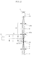
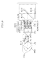
- Fig. 2 is a conceptual view showing an example of a fundamental optical arrangement in the microscope of the present invention.
- the microscope shown in Fig. 2 has an objective lens I, an imaging lens 2, an image sensor 3, an illumination light source 4, and a reflecting fluorescence illumination optical system 6.
- reference symbol P1 represents the pupil position of the objective lens 1
- P2 and P3 represent pupil positions conjugate with the pupil position P1
- O represents the center axis of the objective lens 1 and the imaging lens 2.
- the imaging lens 2 is constructed so that light passing through the objective lens 1 is projected to form the image of a specimen 7.
- the image sensor 3 is placed at the imaging position where the image of the specimen 7 is formed by the imaging lens 2.
- the reflecting fluorescence illumination optical system 6 is designed to have a dichroic mirror 5 introducing light from the illumination light source 4 into the optical path on the objective-lens-1 side and to irradiate the specimen 7 with the light.
- the microscope shown in Fig. 2 in contrast with the conventional microscope such as that shown in Fig. 1 , has a relay optical system 10 forming an intermediate image of the specimen 7, between the objective lens 1 and the imaging lens 2, to relay the image to the imaging lens 2.
- reference symbol Q denotes the imaging position of the intermediate image.
- the dichroic mirror 5 is interposed between the pupil position P2 conjugate with the pupil position P1 of the objective lens 1, formed between the relay optical system 10 and the imaging lens 2, and the relay optical system 10.
- reference numeral 9 denotes a barrier filter cutting off unwanted light, of light from the specimen 7.
- the marginal beam can be prevented from separating from the central beam in going from the objective lens 1 to the imaging lens 2 through the relay optical system 10. Consequently, even though the optical path between the objective lens 1 and the imaging lens 2 is elongated, the eclipse of light passing through the peripheries of the barrier filter 9 and the dichroic mirror 5 can be eliminated and the problem of the insufficiency of the amount of light imaged on the periphery of the image pickup surface of the image sensor 3 is solved so that the amount of light imaged in the entire image pickup area is uniformed and the quantification and reproducibility of a fluorescent image thus obtained can be improved.
- the eclipse of light due to the excitation filter 8 and the dichroic mirror 5 can also be eliminated.
- the dichroic mirror 5 When the dichroic mirror 5 is interposed between the pupil position P2 conjugate with the pupil position P1 of the objective lens 1 and the relay optical system 10, the marginal beam passing through the barrier filter 9 placed in the proximity of the dichroic mirror 5 can be brought close to the central beam. As a result, a part of the marginal beam does not miss the barrier filter 9, so that the brightness and wavelength of fluorescent light imaged on the image pickup surface of the image sensor 3 through the imaging lens 2 are uniformed with respect to the center and periphery of the image pickup surface and the quantification and reproducibility of a fluorescent image thus obtained can be improved.
- the marginal beam incident on the excitation filter 8 can be brought close to the central beam and a part of the marginal beam does not miss the excitation filter 8, so that the brightness and wavelength of excitation light irradiating the surface of the specimen 7 through the objective lens 1 are uniformed with respect to the center and periphery of the irradiated surface and the quantification and reproducibility of a fluorescent image thus obtained can be improved.
- the reflecting fluorescence illumination optical system 6 light from the light source is not eclipsed through the excitation filter 8 with respect to the pupil of the objective lens and it becomes possible to illuminate the specimen with uniform excitation light, so that the unevenness and intensity of illumination of the excitation light on the surface of the specimen are homogenized and the quantification and reproducibility are improved.
- the eclipse due to the excitation filter 8 is prevented and the projection magnification of the light source in the reflecting fluorescence illumination optical system can be increased, with the result that the efficiency of utilization of the light source 4 can be improved.
- the dichroic mirror 5 is placed in the proximity of the pupil position P2 conjugate with the pupil position P1 of the objective lens 1.
- the marginal beam passing through the dichroic mirror 5 can be brought close to the central beam as far as possible, and it becomes easier to obtain eclipse-free and uniformed illumination light and a photographic image.
- this arrangement is suitable for the case where the dichroic mirror 5 is combined with the excitation filter 8 and the barrier filter 9 to constitute a unit such as the fluorescence cube.
- the barrier filter 9 is located at the pupil position P2 conjugate with the pupil position P1 of the objective lens 1 and thereby the marginal beam passing through the barrier filter 9 can be brought closest to the central beam.
- the excitation filter 8 is located at the pupil position P3 conjugate with the pupil position P1 of the objective lens 1 and thereby the beam passing through the excitation filter 8 can be brought closest to the central beam.
- the microscope shown in Fig. 2 is constructed so that a light beam from the specimen 7 is nearly afocal at the pupil position P2 conjugate with the pupil position P1 of the objective lens 1. By doing so, even when the optical path is elongated, the marginal beam can be prevented from separating extremely from the center and hence it becomes easy to obviate the eclipse of the marginal beam.
- the imaging lens 2 is constructed with an imaging optical system (omitted from the figure) provided with a zoom optical system or a variable magnification optical system (omitted from the figure) whose magnification is changed stepwise.
- an imaging optical system (omitted from the figure) provided with a zoom optical system or a variable magnification optical system (omitted from the figure) whose magnification is changed stepwise.
- ⁇ is the pupil relay magnification of the relay optical system from the pupil position P1 of the objective lens to the pupil conjugate position P2.
- ⁇ is the pupil relay magnification of the relay optical system from the pupil position P1 of the objective lens to the pupil conjugate position P2.
- the eclipse of the marginal light due to the barrier filter 9 becomes liable to occur.
- the angle of incidence of light emerging from the relay optical system on the barrier filter 9 increases significantly and a spectral property is impaired by undergoing the influence of the dependence of the barrier filter 9 on the angle of incidence.
- the following equation should more preferably be satisfied: ⁇ ⁇ - 1
- a fly-eye lens (omitted from the figure) is placed in the proximity of the pupil position P3 conjugate with the pupil position P1 of the objective lens 1 in the reflecting fluorescence illumination optical system 6.
- a Köhler illumination system which does not depend on the light-distribution angle characteristic or the luminance distribution characteristic of the light source can be constructed, and the reflecting fluorescence illumination optical system 6 in which uneven illumination on the surface of the specimen is made more uniform and the dependence of the light source on the light-distribution angle is slight can be constructed.
- the illumination light source 4 is constructed with a reflector light source, an LED light source, or a fiber light source.
- the reflector light source the amount of light of the illumination light source 4 can be efficiently utilized.
- the LED light source is used, a long-time observation does not cause damage to an observation object, and a preset wavelength can be used for irradiation in accordance with the application.
- an integrator rod (omitted from the figure) is provided in the reflecting fluorescence illumination optical system 6.
- the integrator rod is constructed in the shape of a square-column glass rod so that light incident on the integrator rod from the light source repeats total reflection in turn and thereby is mixed and illumination distribution is uniformed. By providing critical illumination that the exit end face of the integrator rod is projected on the surface of the specimen, light from the illumination light source 4 can be uniformed.
- the integrator rod is constructed so that its square-column shape is similar to the image pickup area.
- the integrator rod may be constructed with a light pipe in which the square column is hollow and is constructed with a mirror.
- the objective optical system 1, the imaging optical system 2, and the relay optical system 10 are constructed to be nearly telecentric optical systems on the surface of the object, at the position of the intermediate image, and on the surface of the image sensor, respectively.
- a pupil modulation means may be placed in the proximity of the pupil position P2 conjugate with the pupil position P1 of the objective lens 1, formed between the relay optical system 10 and the imaging lens 2.
- observations based on various observation techniques of a phase contrast observation and a differential interference observation, in addition to a fluorescence microscope observation are sometimes required.
- the pupil modulation means (omitted from the figure) is placed instead of the barrier filter 9 in the fluorescence observation, high-precision observation images in which the amounts of light are equalized are obtained with respect to various observations.
- the pupil modulation means is constructed with a variable stop (omitted from the figure).
- the depth of focus of the specimen 7 can be adjusted and, for example, even though a number of sample vessels arranged have individual variations in thickness, the diameter of the variable stop is adjusted and thereby a specimen image at an image quality level that the focus is stable can be obtained.
- the aperture stop is adjusted and thereby, although an effective numerical aperture becomes smaller than the numerical aperture of the objective lens, the loss of the amount of marginal light due to the objective lens is eliminated and the amounts of central and marginal light can be equalized.
- the pupil modulation means is constructed with a member (omitted from the figure) in which a phase film is zonally provided, and a transmitting illumination means (omitted from the figure) is provided to irradiate zonal illumination light corresponding to the member in which the phase film is zonally provided.
- the pupil modulation means may be constructed with a Nomarski prism (omitted from the figure). By doing so, a high-precision phase contrast observation in which the amount of light is uniformed can be carried out over the entire image pickup surface.
- the pupil modulation means may also be constructed with a Hofmann module (omitted from the figure). Also, it is desirable that the pupil modulation means is designed to be movable in and out of the optical path. By such an arrangement, observations based on various observation techniques can be carried out over the entire image pickup surface with a simple operation and with a high degree of accuracy.
- an image restriction means for partially blocking illumination light from the reflecting fluorescence illumination optical system 6 is constructed to be locatable in the proximity of the imaging position Q of the intermediate image of the specimen 7 formed through the relay optical system 10.
- the image restriction means is a rotatable Nipkow disk (omitted from the figure). By doing so, a confocal microscope which is suitable for the physiological reaction observation and morphology observation of the cell can be constructed.
- the image restriction means is a rotatable slit member (omitted from the figure). By doing so, only light from a focal plane passes through the slit member and blurred images before and behind the focal plane are cut off by the slit member so that an image in which blurring is eliminated in the entire image pickup area is obtained.
- an aperture (omitted from the figure) through which illumination light from the reflecting fluorescence illumination optical system 6 can pass is configured into a rectangular shape corresponding to the shape of the image pickup surface of the image sensor 3.
- a deflection member such as a mirror, deflecting an optical path from the objective lens 1 to the imaging lens 2 in a nearly horizontal direction is located at a preset place between the objective lens 1 and the relay optical system 10.
- a split means splitting the optical path into an optical path picked up by the image sensor and an optical path for visual observation is provided at a preset position on the optical path from the objective lens 1 to the imaging lens 2, deflected through the deflection member.
- the specimen is illuminated with light of infrared wavelength used for focal position detection, through the objective lens, and the focal position can be detected with high accuracy through a light-receiving element provided in the autofocus correction mechanism by reflected light from the surface or vessel surface of the specimen.
- the autofocus correction mechanism any mechanism that the specimen is irradiated with light of a preset wavelength and reflected light from the specimen is received so that the focal position can be corrected in accordance with a light-received state is applicable.
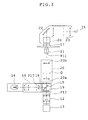
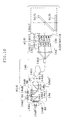
- Fig. 3 is an explanatory view showing a schematic structure of the whole of the microscope according to the first aspect of the present invention.
- the microscope of the first aspect has an objective lens 11, an imaging lens 12, an image sensor 13, an illumination light source 14, a reflecting fluorescence illumination optical system 16, a transmitting illumination light source 21, and a transmitting illumination optical system 22.
- reference symbol P11 represents the pupil position of the objective lens 11
- P12 and P 13 represent pupil positions conjugate with the pupil position P11
- O represents the center axis of the objective lens 11 and the imaging lens 12.
- the imaging lens 12 is designed so that light passing through the objective lens 11 is projected to form the image of a specimen 17.
- the image sensor 13 is constructed with a CCD camera and is placed so that its image pickup surface is located at the imaging position where the image of the specimen 17 is formed by the imaging lens 12.
- the illumination light source 14 is constructed with a reflector light source. Also, it may be constructed with an LED light source or a fiber light source (omitted from the figure).
- the reflecting fluorescence illumination optical system 16 is designed to have a dichroic mirror 15 introducing light from the illumination light source 14 into the optical path on the objective-lens-11 side and to illuminate the specimen 17 with the light.
- the transmitting illumination optical system 22 is constructed with a transmitting illumination lens 23 and a condenser lens 24.
- the microscope of the first aspect further has a relay optical system 20 forming an intermediate image of the specimen 17 to relay the image to the imaging lens 12, between the objective lens 11 and the imaging lens 12.
- reference symbol Q denotes the imaging position of the intermediate image.
- the dichroic mirror 15 is placed between the pupil position P12 conjugate with the pupil position P11 of the objective lens 11, formed between the relay optical system 20 and the imaging lens 12, and the relay optical system 20 and in the proximity of the pupil position 12.
- a barrier filter 19 is placed in the proximity of the pupil position P12. In the proximity of the pupil position P13 conjugate with the pupil position P11 of the objective lens 11, an excitation filter 18 is placed. Also, it is desirable that the barrier filter 19 is located at the pupil position P12.
- the excitation filter 18 is located at the pupil position P13.
- the dichroic mirror 15, the excitation filer 18, and the barrier filter 19 are constructed as a single cubic unit to be movable in and out of the optical path.
- the imaging lens 12 is constructed with an imaging optical system provided with a zoom optical system so that a light beam from the specimen 17 is nearly afocal at the pupil position P12.
- variable magnification optical system (omitted from the figure) whose magnification is changed stepwise, constructed so that, for example, a turret or a slider provided with lenses of different magnifications is rotated or slid and thereby a lens of a desired magnification can be placed on the optical path.
- the relay optical system 20 is designed to satisfy the following condition: 0.6 ⁇ ⁇ ⁇ 1.5 where ⁇ is a pupil relay magnification.
- the objective optical system 11, the imaging optical system 12, and the relay optical system 20 are constructed to be nearly telecentric optical systems on the surface of the object, at the position of the intermediate image, and on the surface of the image sensor, respectively.
- the microscope of the first aspect is constructed so that a fly-eye lens (omitted from the figure) can be located at the pupil position P13 in the reflecting fluorescence illumination optical system 16. Also, the microscope may be constructed to have an integrator rod (omitted from the figure) in the reflecting fluorescence illumination optical system 16.
- the microscope of the first aspect is constructed so that a pupil modulation mean can be placed in the proximity of the pupil position P12 to be movable in and out of the optical path.
- a pupil modulation means for example, a phase plate (omitted from the figure) in which a phase film is zonally provided can be used.
- a condenser for phase contrast observation provided with a ring-shaped slit (omitted from the figure), constructed so that the specimen 17 can be irradiated with zonal illumination light corresponding to the phase plate, is used for the condenser lens 24 of the transmitting illumination optical system 22. By doing so, the phase contrast observation can be carried out.
- pupil modulation means in the microscope of the first aspect for example, a variable stop, a Nomarski prism, and a Hofmann module (all omitted from the figure) are applicable.
- the microscope of the first aspect is constructed so that an image restriction means (omitted from the figure) for partially blocking illumination light from the reflecting fluorescence illumination optical system 16 can be located in the proximity of the imaging position Q where the intermediate image of the specimen 17 is formed through the relay optical system 20.
- an image restriction means a rotatable Nipkow disk (omitted from the figure) and a rotatable slit member (omitted from the figure) can be used.
- the Nipkow disk or the rotatable slit member is placed at the position of the intermediate image, a nearly telecentric optical system is constructed.
- the image restriction means it is also possible to use a light blocking member (omitted from the figure) that an aperture through which illumination light from the reflecting fluorescence illumination optical system 16 can pass is configured into a rectangular shape corresponding to the shape of the image pickup surface of the image sensor 13.
- zoom and variable magnification functions are imparted to the imaging optical system 12, the size of the aperture of the image restriction means is made variable in accordance with an imaging magnification. By making the size of the aperture variable, an area in which the specimen is irradiated with excitation light is kept to a minimum and the influence of bleaching of the specimen can be lessened.
- a deflection member (omitted from the figure), such as a mirror, deflecting an optical path from the objective lens 11 to the imaging lens 12 in a nearly horizontal direction is located at a preset place between the objective lens 11 and the relay optical system 20.
- a split means splitting the optical path into an optical path picked up by the image sensor 13 and an optical path for visual observation is provided at a preset position on the optical path from the objective lens 11 to the imaging lens 12, deflected through the deflection member.
- the microscope of the first aspect is such that an autofocus correction mechanism can also be provided between the objective lens 11 and the imaging lens 12. Also, in the autofocus correction mechanism, any mechanism that the specimen is irradiated with light of a preset wavelength and reflected light from the specimen is received so that the focal position can be corrected in accordance with a light-received state is applicable.
- a marginal beam can be prevented from separating from a central beam in going from the objective lens 11 to the imaging lens 12 through the relay optical system 20. Consequently, even though the optical path between the objective lens 11 and the imaging lens 12 is elongated, the eclipse of light passing through the peripheries of the barrier filter 19 and the dichroic mirror 15 can be eliminated and the problem of the insufficiency of the amount of light imaged on the periphery of the image pickup surface of the image sensor 13 is solved so that the amount of light imaged in the entire image pickup area can be uniformed.
- the dichroic mirror 15 Since the dichroic mirror 15 is interposed between the pupil position P12 conjugate with the pupil position P11 of the objective lens 11 and the relay optical system 20, the marginal beam passing through the barrier filter 19 placed in the proximity of the dichroic mirror 15 can be brought close to the central beam. As a result, a part of the marginal beam does not miss the barrier filter 19, so that the brightness and wavelength of fluorescent light imaged on the image pickup surface of the image sensor 13 through the imaging lens 12 are uniformed with respect to the center and periphery of the image pickup surface.
- the marginal beam incident on the excitation filter 18 can be brought close to the central beam and a part of the marginal beam does not miss the excitation filter 18, so that the brightness and wavelength of excitation light irradiating the surface of the specimen 17 through the objective lens 11 are uniformed with respect to the center and periphery of the irradiated surface and the quantification and reproducibility of a fluorescent image thus obtained can be improved.
- the eclipse due to the excitation filter 18 is prevented and the magnification of light source projection of the reflecting fluorescence illumination optical system 16 can be increased, with the result that the efficiency of utilizatin of the light source 14 can be improved.
- the dichroic mirror 15 is placed in the proximity of the pupil position P12 conjugate with the pupil position P11 of the objective lens 11, the marginal beam passing through the dichroic mirror 15 can be brought close to the central beam as far as possible, and it becomes easier to obtain eclipse-free and uniformed illumination light and a photographic image.
- This arrangement is suitable for the case where the dichroic mirror 15 is combined with the excitation filter 8 and the barrier filter 9 to constitute a unit such as the fluorescence cube.
- the barrier filter 19 is located at the pupil position P12 conjugate with the pupil position P11 of the objective lens 11, the most favorable arrangement is obtained. By doing so, the marginal beam passing through the barrier filter 19 can be brought closest to the central beam.
- the excitation filter 18 is located at the pupil position P13 conjugate with the pupil position P11 of the objective lens 11, the most favorable arrangement is obtained. By doing so, the beam passing through the excitation filter 18 can be brought closest to the central beam.
- the imaging lens 12 is constructed with the imaging optical system provided with the zoom optical system so that the light beam from the specimen 17 is nearly afocal at the pupil position P12 conjugate with the pupil position P11 of the objective lens 11, and thus even when the optical path is elongated, the marginal beam can be prevented from separating extremely from the center. Hence, it becomes easy to obviate the eclipse of the marginal beam. Moreover, since the zoom optical system is used, various observation magnifications can be accommodated.
- the following condition is satisfied: 0.6 ⁇ ⁇ ⁇ 1.5
- ⁇ is the pupil relay magnification of the relay optical system 20 from the pupil position P11 of the objective lens 11 to the pupil conjugate position P12.
- the objective optical system 11, the imaging optical system 12, and the relay optical system 20 are constructed to be nearly telecentric optical systems on the surface of the object, at the position of the intermediate image, and on the surface of the image sensor, respectively, angles of rays from the center to the periphery are equalized and the phenomenon of shading inherent in the image sensor is suppressed so that the uniformity of the amount of light can be ensured.
- a fly-eye lens (omitted from the figure) can be placed at the pupil position P13 conjugate with the pupil position P11 of the objective lens 11 in the reflecting fluorescence illumination optical system 16.
- the wavelength and amount of illumination light can be further uniformed.
- a Köhler illumination system which does not depend on the light-distribution angle characteristic or the luminance distribution characteristic of the light source can be constructed, and the reflecting fluorescence illumination optical system 16 in which uneven illumination on the surface of the specimen is made more uniform and the dependence of the illumination light source 14 on the light-distribution angle is slight can be constructed.
- the illumination light source 14 is constructed with the reflector light source and hence the amount of light of the illumination light source 14 can be effectively utilized. Also, when the LED light source is used as the illumination light source 14, a long-time observation does not cause damage to an observation object, and a preset wavelength can be used for irradiation in accordance with the application.
- the microscope when the microscope is constructed to have an integrator rod (omitted from the figure) in the reflecting fluorescence illumination optical system 16, light from the illumination light source 14 can be uniformed.
- the integrator rod is constructed in the shape of a square-column glass rod so that light incident on the integrator rod from the light source repeats total reflection in turn and thereby is mixed and illumination distribution is uniformed.
- the integrator rod is constructed so that its square-column shape is similar to the image pickup area.
- the integrator rod may be constructed with a light pipe in which the square column is hollow and is constructed with a mirror.
- a pupil modulation means (omitted from the figure) is placed to be movable in and out of the optical path in the proximity of the pupil position P12 conjugate with the pupil position P11 of the objective lens 11, formed between the relay optical system 20 and the imaging lens 12, observations based on various observation techniques can be carried out over the entire image pickup surface with a simple operation and with a high degree of accuracy.
- the pupil modulation means in the proximity of the pupil position P12, the depth of focus of the specimen 17 can be adjusted, and for example, even though a number of sample vessels arranged have individual variations in thickness, the diameter of the variable stop is adjusted and thereby a specimen image at an image quality level that the focus is stable can be obtained.
- the aperture stop is adjusted and thereby, although an effective numerical aperture becomes smaller than the numerical aperture of the objective lens, the loss of the amount of marginal light due to the objective lens 11 is eliminated and the amounts of central and marginal light can be equalized.
- the condenser for phase contrast observation provided with a ring-shaped slit (omitted from the figure), constructed so that the specimen 17 can be irradiated with zonal illumination light corresponding to the phase plate, is used as the condenser lens 24 of the transmitting illumination optical system 22.
- the pupil modulation means is constructed with a Nomarski prism as another means, a high-precision phase contrast observation in which the amount of light is uniformed can be carried out over the entire image pickup surface.
- an image restriction means for partially blocking illumination light from the reflecting fluorescence illumination optical system 16 is constructed to be locatable in the proximity of the imaging position Q where the intermediate image of the specimen 17 is formed through the relay optical system 20.
- the image restriction means is constructed with a rotatable Nipkow disk (omitted from the figure)
- a confocal microscope which is suitable for the physiological reaction observation and morphology observation of the cell can be constructed.
- the image restriction means When the image restriction means is constructed with a rotatable slit member (omitted from the figure), only light from a focal plane passes through the slit member and blurred images before and behind the focal plane are cut off by the slit member so that an image in which blurring is eliminated in the entire image pickup area is obtained.
- an aperture (omitted from the figure) through which illumination light from the reflecting fluorescence illumination optical system 16 can pass is configured into a rectangular shape corresponding to the shape of the image pickup surface of the image sensor 13, irradiation to the specimen 17 can be restricted within a necessary limit and damage to the specimen 17 and fluorescence bleaching can be kept to a minimum.
- a deflection member such as a mirror, deflecting the optical path from the objective lens 11 to the imaging lens 12 in a nearly horizontal direction is located at a preset place between the objective lens 11 and the relay optical system 20.
- a vertical length of the microscope can be kept by bending the optical path in the horizontal direction, and hence a viewer is capable of making the observation in a natural position.
- a split means splitting the optical path into an optical path picked up by the image sensor 13 and an optical path for visual observation is provided at a preset position on the optical path from the objective lens 11 to the imaging lens 12, deflected through the deflection member.
- an autofocus correction mechanism (omitted from the figure) is provided between the objective lens 11 and the imaging lens 12, and thereby a sharp observation image is obtained without performing the manual operation of focus adjustment.
- the specimen is illuminated with light of infrared wavelength used for focal position detection, through the objective lens, and the focal position can be detected with high accuracy through a light-receiving element provided in the autofocus correction mechanism by reflected light from the surface or vessel surface of the specimen.
- the marginal beam can be prevented from separating from the central beam in going from the objective lens 11 to the imaging lens 12 through the relay optical system 20. Consequently, even though the optical path between the objective lens 11 and the imaging lens 12 is elongated, the eclipse of light passing through the peripheries can be eliminated and the problem of the insufficiency of the amount of light imaged on the periphery of the image pickup surface of the image sensor 13 is solved so that the amount of light imaged in the entire image pickup area can be uniformed.
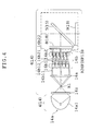
- Fig. 4 is an explanatory view showing the arrangement of an illumination light source and a reflecting fluorescence illumination optical system in the microscope according to Embodiment 1 of the present invention.
- the illumination light source 4 (14) is constructed with a collection-type reflector light source 14a.
- the reflecting fluorescence illumination optical system 6 (16) includes a collector lens 16a, a fly-eye lens 16b, the excitation filter 8 (18), and the dichroic mirror 5 (15).
- reference numeral 9 (19) represents the barrier filter.
- the reflector light source 14a is constructed with an arc light source, such as a mercury lamp or a metal halide lamp, provided with an elliptical reflector mirror 14a1.
- the elliptical reflector mirror 14a1 is constructed so that a convergent beam is emitted by reflection to form a primary light source image at a primary imaging position R1.
- the collector lens 16a is constructed so that a light beam diverging from the primary imaging position R1 is converted into a parallel beam.
- the fly-eye lens 16b includes a first fly-eye lens 16b1 and a second fly-eye lens 16b2.
- the first fly-eye lens 16b1 is constructed with an array of a plurality of lenses whose entrance end faces 16b11 are each configured to be convex and whose exit end faces 16b12 to be flat.
- the second fly-eye lens 16b2 is constructed with an array of a plurality of lenses whose entrance end faces 16b21 are each configured to be flat and whose exit end faces 16b22 to be convex.
- the contour of each lens array assumes the shape of a hexagon or a rectangle.
- the second fly-eye lens 16b2 is placed so that the position of the exit end faces 16b22 practically coincides with the pupil position P3 (P13) conjugate with the pupil position of the objective lens (omitted from the figure).
- the fly-eye lens 16b is such that a parallel beam emerging from the collector lens 16a is split into a plurality of beams to form a plurality of secondary light source images in the reflector light source 14a at a secondary imaging position R2 in the proximity of the exit end faces 16b22 of the second fly-eye lens 16b2.
- the fly-eye lens 16b may be designed to use a lens array in which convex surfaces are integrally provided on both its entrance end faces and exit end faces.
- an infrared cutoff filter 16z is interposed between the reflector light source 14a and the primary imaging position R1. Also, it is desirable that the back focal position of the collector lens 16a practically coincides with the position of the entrance end faces of the fly-eye lens 16b (the entrance end faces 16b11 of the first fly-eye lens T6b1). As for the rest, an aperture stop (omitted from the figure) is placed in the proximity of the exit end faces of the fly-eye lens 16b (the exit end faces 16b22 of the second fly-eye lens 16b2). Between the reflector light source 14a and the excitation filter 8 (18), a shutter section (omitted from the figure) for cutting off the light beam from the reflector light source 14a is provided.
- the locations and structures of the objective lens (omitted from the figure), the imaging lens (omitted from the figure), the excitation filter 8 (18), the dichroic mirror 5 (15), the barrier filter 9 (19), the relay optical system (omitted from the figure), and other members are almost the same as in the microscope shown in Fig. 2 or the microscope of the first aspect shown in Fig. 3 .
- the convergent beam emitted from the reflector light source 14a forms the primary light source image at the primary imaging position R1 after the infrared wavelength is removed by the infrared cutoff filter 16z, and changes into a divergent beam from the primary imaging position R1 to enter the collector lens 16a.
- the divergent beam incident on the collector lens 16a is converted by the collector lens 16a into a parallel beam, which is incident on the first fly-eye lens 16b1.
- the parallel beam incident on the first fly-eye lens 16b1 is split into a plurality of beams converged through a plurality of entrance end faces 16b11, which are incident on the second fly-eye lens 16b2 and form a plurality of secondary light source images at the secondary imaging position R2 in the proximity of the exit end faces 16b22 of the second fly-eye lens 16b2.
- the collection-type reflector light source 14a forming the light source image is used as the illumination light source, and hence the optical arrangement of the illumination light source and the reflecting fluorescence illumination optical system can be made compact.
- Other functions and effects are almost the same as in the microscope shown in Fig. 2 or the microscope of the first aspect shown in Fig. 3 .
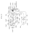
- Fig. 5 is an explanatory view showing the arrangement of an illumination light source and a reflecting fluorescence illumination optical system in the microscope according to Embodiment 2 of the present invention.
- the illumination light source 4 (14) is constructed with a parallel-beam-type reflector light source 14a'.
- the reflecting fluorescence illumination optical system 6 (16) includes an afocal system 16a', the fly-eye lens 16b, the excitation filter 8 (18), and the dichroic mirror 5 (15).
- reference numeral 9 (19) represents the barrier filter.
- the reflector light source 14a' is constructed with an arc light source, such as a mercury lamp or a metal halide lamp, provided with an elliptical reflector mirror 14a1'.
- the elliptical reflector mirror 14a1' is constructed so that a parallel beam is emitted by reflection.
- the afocal system 16a' is constructed so that the diameter of the parallel beam emitted from the reflector light source 14a' is converted to become nearly equal to that of the fly-eye lens 16b.
- the fly-eye lens 16b includes the first fly-eye lens 16b1 and the second fly-eye lens 16b2.
- the first fly-eye lens 16b1 is constructed with an array of a plurality of lenses whose entrance end faces 16b11 are each configured to be convex and whose exit end faces 16b12 to be flat.
- the second fly-eye lens 16b2 is constructed with an array of a plurality of lenses whose entrance end faces 16b21 are each configured to be flat and whose exit end faces 16b22 to be convex.
- each lens array assumes the shape of a hexagon or a rectangle.
- the second fly-eye lens 16b2 is placed so that the position of the exit end faces 16b22 practically coincides with the pupil position P3 (P13) conjugate with the pupil position of the objective lens (omitted from the figure).
- the fly-eye lens 16b is such that a parallel beam emerging from the afocal system 16a' is split into a plurality of beams to form a plurality of primary light source images of the reflector light source 14a' at the primary imaging position R1 in the proximity of the exit end faces 16b22 of the second fly-eye lens 16b2.
- the fly-eye lens 16b may be designed to use a lens array in which convex surfaces are integrally provided on both its entrance end faces and exit end faces. Between the reflector light source 14a' and the afocal system 16a', the infrared cutoff filter 16z is interposed. Also, it is desirable that the back focal position of the afocal system 16a' practically coincides with the position of the entrance end faces of the fly-eye lens 16b (the entrance end faces 16b11 of the first fly-eye lens 16b1). As for the rest, the aperture stop (omitted from the figure) is placed in the proximity of the exit end faces of the fly-eye lens 16b (the exit end faces 16b22 of the second fly-eye lens 16b2).
- the shutter section (omitted from the figure) for cutting off the light beam from the reflector light source 14a' is provided.
- the locations and structures of the objective lens (omitted from the figure), the imaging lens (omitted from the figure), the excitation filter 8 (18), the dichroic mirror 5 (15), the barrier filter 9 (19), the relay optical system (omitted from the figure), and other members are almost the same as in the microscope shown in Fig. 2 or the microscope of the first aspect shown in Fig. 3 .
- the parallel beam emitted from the reflector light source 14a' is incident on the afocal system 16a' after the infrared wavelength is removed by the infrared cutoff filter 16z.
- the parallel beam incident on the afocal system 16a' is converted so that its beam diameter becomes nearly equal to the diameter of the fly-eye lens 16b, and is incident on the first fly-eye lens 16b1.
- the parallel beam incident on the first fly-eye lens 16b1 is split into a plurality of beams converged through a plurality of entrance end faces 16b11, which are incident on the second fly-eye lens 16b2 and form a plurality of primary light source images at the primary imaging position R1 in the proximity of the exit end faces 16b22 of the second fly-eye lens 16b2.
- the parallel-beam-type reflector light source 14a' emitting the parallel beam is used as the illumination light source, and hence the number of degrees of length freedom in the direction of the optical axis in the optical arrangement of the illumination light source and the reflecting fluorescence illumination optical system becomes large and the number of degrees of placement freedom of constituent members can be increased.
- Other functions and effects are almost the same as in the microscope shown in Fig. 2 or the microscope of the first aspect shown in Fig. 3 .
- Fig. 6 is an explanatory view showing the arrangement of an illumination light source and a reflecting fluorescence illumination optical system in the microscope according to Embodiment 3 of the present invention.
- the illumination light source 4 (14) is constructed with the parallel-beam-type reflector light source 14a'.
- the reflecting fluorescence illumination optical system 6 (16) includes an afocal system 16a", the fly-eye lens 16b, the excitation filter 8 (18), and the dichroic mirror 5 (15).
- reference numeral 9(19) represents the barrier filter.
- the reflector light source 14a' is constructed with the arc light source, such as a mercury lamp or a metal halide lamp, provided with the elliptical reflector mirror 14a1'.
- the elliptical reflector mirror 14a1' is constructed so that a parallel beam is emitted by reflection.
- the afocal system 16a" is constructed so that the parallel beam emitted from the reflector light source 14a' is condensed to form the light source image of the reflector light source 14a' at the primary imaging position R1 inside the system, and then the beam is converted into a parallel beam whose diameter is nearly equal to that of the fly-eye lens 16b and emerges therefrom.
- the fly-eye lens 16b includes the first fly-eye lens 16b1 and the second fly-eye lens 16b2.
- the first fly-eye lens 16b1 is constructed with an array of a plurality of lenses whose entrance end faces 16b11 are each configured to be convex and whose exit end faces 16b12 to be flat.
- the second fly-eye lens 16b2 is constructed with an array of a plurality of lenses whose entrance end faces 16b21 are each configured to be flat and whose exit end faces 16b22 to be convex.
- the contour of each lens array assumes the shape of a hexagon or a rectangle.
- the second fly-eye lens 16b2 is placed so that the position of the exit end faces 16b22 practically coincides with the pupil position P3 (P13) conjugate with the pupil position of the objective lens (omitted from the figure).
- the fly-eye lens 16b is such that the parallel beam emerging from the afocal system 16a" is split into a plurality of beams to form a plurality of secondary light source images of the reflector light source 14a' at the secondary imaging position R2 in the proximity of the exit end faces 16b22 of the second fly-eye lens 16b2. Also, the fly-eye lens 16b may be designed to use a lens array in which convex surfaces are integrally provided on both its entrance end faces and exit end faces.
- the infrared cutoff filter 16z is interposed between the reflector light source 14a' and the afocal system 16a". Also, it is desirable that the back focal position of the afocal system 16a" practically coincides with the position of the entrance end faces of the fly-eye lens 16b (the entrance end faces 16b11 of the first fly-eye lens 16b1). As for the rest, the aperture stop (omitted from the figure) is placed in the proximity of the exit end faces of the fly-eye lens 16b (the exit end faces 16b22 of the second fly-eye lens 16b2). Between the reflector light source 14a' and the excitation filter 8 (18), the shutter section (omitted from the figure) for cutting off the light beam from the reflector light source 14a' is provided.
- the locations and structures of the objective lens (omitted from the figure), the imaging lens (omitted from the figure), the excitation filter 8 (18), the dichroic mirror 5 (15), the barrier filter 9 (19), the relay optical system (omitted from the figure), and other members are almost the same as in the microscope shown in Fig. 2 or the microscope of the first aspect shown in Fig. 3 .
- the parallel beam emitted from the reflector light source 14a' is incident on the afocal system 16a" after the infrared wavelength is removed by the infrared cutoff filter 16z.
- the parallel beam incident on the afocal system 16a" is condensed to form the primary light source image at the primary imaging position R1 inside the system, and then the beam is converted into a parallel beam whose diameter is nearly equal to that of the fly-eye lens 16b, which emerges therefrom to enter the first fly-eye lens 16b1.
- the parallel beam incident on the first fly-eye lens 16b1 is split into a plurality of beams converged through a plurality of entrance end faces 16b11, which are incident on the second fly-eye lens 16b2 and form a plurality of secondary light source images at the secondary imaging position R2 in the proximity of the exit end faces 16b22 of the second fly-eye lens 16b2.
- the parallel-beam-type reflector light source 14a' emitting a parallel beam is used as the illumination light source, and hence the number of degrees of length freedom in the direction of the optical axis in the optical arrangement of the illumination light source and the reflecting fluorescence illumination optical system becomes large and the number of degrees of placement freedom of constituent members can be increased.
- Other functions and effects are almost the same as in the microscope shown in Fig. 2 or the microscope of the first aspect shown in Fig. 3 .
- Fig. 7 is an explanatory view showing the arrangement of an illumination light source and a reflecting fluorescence illumination optical system in the microscope according to Embodiment 4 of the present invention.
- the illumination light source 4 (14) has the collection-type reflector light source 14a and an optical fiber 14b.
- the reflecting fluorescence illumination optical system 6 (16) includes the collector lens 16a, the fly-eye lens 16b, the excitation filter 8 (18), and the dichroic mirror 5 (15).
- reference numeral 9 (19) represents the barrier filter.
- the reflector light source 14a is constructed with the arc light source, such as a mercury lamp or a metal halide lamp, provided with the elliptical reflector mirror 14a1.
- the elliptical reflector mirror 14a1 is constructed so that a convergent beam is emitted by reflection to form the primary light source image at the primary imaging position R1.
- the parallel-beam-type reflector light source may be used so that a lens in which a parallel beam emitted from the parallel-beam-type reflector light source is condensed to perform the primary formation of the light source image of the reflector light source is interposed between the optical fiber 14b and the reflector light source.
- the illumination light source 4 (14) may be designed to use an LED or a short-arc extra-high voltage mercury lamp as another light source.
- the optical fiber 14b is placed so that its entrance end face 14b1 is located at the primary imaging position R1 of the light source image of the reflector light source 14a.
- any structural fiber such as a liquid fiber or a bundle fiber, can be used.
- the collector lens 16a is constructed so that a divergent beam emerging from an exit end face 14b2 of the optical fiber 14b is converted into a parallel beam.
- the fly-eye lens 16b includes the first fly-eye lens 16b1 and the second fly-eye lens 16b2.
- the first fly-eye lens 16b is constructed with an array of a plurality of lenses whose entrance end faces 16b11 are each configured to be convex and whose exit end faces 16b12 to be flat.
- the second fly-eye lens 16b2 is constructed with an array of a plurality of lenses whose entrance end faces 16b21 are each configured to be flat and whose exit end faces 16b22 to be convex.
- the contour of each lens array assumes the shape of a hexagon or a rectangle.
- the second fly-eye lens 16b2 is placed so that the position of the exit end faces 16b22 practically coincides with the pupil position P3 (P13) conjugate with the pupil position of the objective lens (omitted from the figure).
- the fly-eye lens 16b is such that a parallel beam emerging from the collector lens 16a is split into a plurality of beams to form a plurality of secondary light source images of the reflector light source 14a at the secondary imaging position R2 in the proximity of the exit end faces 16b22 of the second fly-eye lens 16b2.
- the fly-eye lens 16b may be designed to use a lens array in which convex surfaces are integrally provided on both its entrance end faces and exit end faces.
- an infrared cutoff filter 14z is interposed between the reflector light source 14a and the optical fiber 14b. Also, it is desirable that the back focal position of the collector lens 16a practically coincides with the position of the entrance end faces of the fly-eye lens 16b (the entrance end faces 16b11 of the first fly-eye lens 16b1). As for the rest, the aperture stop (omitted from the figure) is placed in the proximity of the exit end faces of the fly-eye lens 16b (the exit end faces 16b22 of the second fly-eye lens 16b2). Between the reflector light source 14a and the excitation filter 8 (18), the shutter section (omitted from the figure) for cutting off the light beam from the reflector light source 14a is provided.
- the locations and structures of the objective lens (omitted from the figure), the imaging lens (omitted from the figure), the excitation filter 8 (18), the dichroic mirror 5 (15), the barrier filter 9 (19), the relay optical system (omitted from the figure), and other members are almost the same as in the microscope shown in Fig. 2 or the microscope of the first aspect shown in Fig. 3 .
- the convergent beam emitted from the reflector light source 14a forms the primary light source image at the primary imaging position R1 after the infrared wavelength is removed by the infrared cutoff filter 14z, and is incident on the entrance end face 14b1 of the optical fiber 14b.
- Light incident on the entrance end face 14b1 of the optical fiber 14b emerges as a divergent beam from the exit end face 14b2.
- the divergent beam emerging from the exit end face 14b2 of the optical fiber 14b is incident on the collector lens 16a.
- the divergent beam incident on the collector lens 16a is converted by the collector lens 16a into a parallel beam, which is incident on the first fly-eye lens 16b1.
- the parallel beam incident on the first fly-eye lens 16b1 is split into a plurality of beams converged through a plurality of entrance end faces 16b11, which are incident on the second fly-eye lens 16b2 and form a plurality of secondary light source images at the secondary imaging position R2 in the proximity of the exit end faces 16b22 of the second fly-eye lens 16b2.
- the optical fiber 14b is placed in the reflecting fluorescence illumination optical system, and hence the number of degrees of kind and placement freedom of the illumination light source can be increased.
- Other functions and effects are almost the same as in the microscope shown in Fig. 2 or the microscope of the first aspect shown in Fig. 3 .
- Fig. 8 is an explanatory view showing the arrangement of an illumination light source and a reflecting fluorescence illumination optical system in the microscope according to Embodiment 5 of the present invention.
- the microscope of Embodiment 5 is constructed to have an integrator rod 14c instead of the optical fiber 14b in the microscope of Embodiment 4 shown in Fig. 7 .
- the reflector light source 14a is constructed with the arc light source, such as a mercury lamp or a metal halide lamp, provided with the elliptical reflector mirror 14a1.
- the elliptical reflector mirror 14a1 is constructed so that a convergent beam is emitted by reflection to form the primary light source image at the primary imaging position R1.
- the parallel-beam-type reflector light source may be used so that a lens in which a parallel beam emitted from the parallel-beam-type reflector light source is condensed to perform the primary formation of the light source image of the reflector light source is interposed between the integrator rod 14c and the reflector light source.
- the illumination light source 4 (14) may be designed to use an LED or a short-arc extra-high voltage mercury lamp as another light source.
- the integrator rod 14c is constructed with a columnar member of a square-column glass rod shape made from glass material with high ultraviolet transmittance or a light pipe including a hollow square-column mirror so that light incident on the interior repeats total reflection in turn and thereby is mixed and illumination distribution is equalized.
- An exit end face 14c2 of the integrator rod 14c serves as the plane of the secondary light source image.
- the cross section of the integrator rod 14c is configured into a rectangular shape similar to the image pickup area of the image sensor (omitted from the figure).
- the integrator rod 14c is placed so that its entrance end face 14c1 is located at the primary imaging position R1 of the light source image of the reflector light source 14a.
- the collector lens 16a is designed so that a divergent beam emerging from the exit end face 14c2 of the integrator rod 14c is converted into a parallel beam.
- Other features are almost the same as in the microscope of Embodiment 4 shown in Fig. 7 .
- the convergent beam emitted from the reflector light source 14a forms the primary light source image at the primary imaging position R1 after the infrared wavelength is removed by the infrared cutoff filter 14z, and is incident on the entrance end face 14c1 of the integrator rod 14c.
- Light incident on the entrance end face 14c1 of the integrator rod 14c is diffusely reflected in the interior and thereby is made uniform in light intensity distribution to emerge as a divergent beam from the exit end face 14c2.
- the divergent beam emerging from the exit end face 14c2 of the integrator rod 14c is incident on the collector lens 16a.
- the divergent beam incident on the collector lens 16a is converted by the collector lens 16a into a parallel beam, which is incident on the first fly-eye lens 16b1.
- the parallel beam incident on the first fly-eye lens 16b1 is split into a plurality of beams converged through a plurality of entrance end faces 16b11, which are incident on the second fly-eye lens 16b2 and form a plurality of secondary light source images at the secondary imaging position R2 in the proximity of the exit end faces 16b22 of the second fly-eye lens 16b2.
- the reflecting fluorescence illumination optical system is provided with the integrator rod 14c, and hence the uniformity of illumination is further improved by combining the integrator rod 14c with the fly-eye lens 16b.
- the integrator rod when used, unevenness of a light intensity due to angles of emergent rays is produced, but in the microscope of Embodiment 5, the unevenness of the light intensity is eliminated by the fly-eye lens 16b and the light intensity can be equalized.
- Other functions and effects are almost the same as in the microscope shown in Fig. 2 or the microscope of the first aspect shown in Fig. 3 .
- Fig. 9 is an explanatory view showing the arrangement of an illumination light source and a reflecting fluorescence illumination optical system in the microscope according to Embodiment 6 of the present invention.
- the illumination light source 4 (14) is constructed with an LED light source 14a".
- the reflecting fluorescence illumination optical system 6 (16) includes a collector lens 16a"', the fly-eye lens 16b, the excitation filter 8 (18), and the dichroic mirror 5 (15).
- reference numeral 9 (19) denotes the barrier filter.
- the collector lens 16a"' is designed so that a divergent beam emitted from the LED light source 14a" is converted into a parallel beam.
- the fly-eye lens 16b includes the first fly-eye lens 16b1 and the second fly-eye lens 16b2.
- the first fly-eye lens 16b1 is constructed with an array of a plurality of lenses whose entrance end faces 16b 11 are each configured to be convex and whose exit end faces 16b12 to be flat.
- the second fly-eye lens 16b2 is constructed with an array of a plurality of lenses whose entrance end faces 16b21 are each configured to be flat and whose exit end faces 16b22 to be convex.
- the contour of each lens array assumes the shape of a hexagon or a rectangle.
- the second fly-eye lens 16b2 is placed so that the position of the exit end faces 16b22 practically coincides with the pupil position P3 (P13) conjugate with the pupil position of the objective lens (omitted from the figure).
- the fly-eye lens 16b is such that the parallel beam emerging from the collector lens 16a"' is split into a plurality of beams to form a plurality of primary light source images of the LED light source 14a" at the primary imaging position R1 in the proximity of the exit end faces 16b22 of the second fly-eye lens 16b2.
- the fly-eye lens 16b may be designed to use a lens array in which convex surfaces are integrally provided on both its entrance end faces and exit end faces.
- the back focal position of the collector lens 16a"' practically coincides with the position of the entrance end faces of the fly-eye lens 16b (the entrance end faces 16b11 of the first fly-eye lens 16b1).
- the aperture stop (omitted from the figure) is placed in the proximity of the exit end faces of the fly-eye lens 16b (the exit end faces 16b22 of the second fly-eye lens 16b2).
- the shutter section (omitted from the figure) for cutting off the light beam from the LED light source 14a" is provided.
- the locations and structures of the objective lens (omitted from the figure), the imaging lens (omitted from the figure), the excitation filter 8 (18), the dichroic mirror 5 (15), the barrier filter 9 (19), the relay optical system (omitted from the figure), and other members are almost the same as in the microscope shown in Fig. 2 or the microscope of the first aspect shown in Fig. 3 .
- the microscope of Embodiment 6 constructed as mentioned above the convergent beam emitted from the LED light source 14a" is incident on the collector lens 16a"'.
- the divergent beam incident on the collector lens 16a"' is converted by the collector lens 16a"' into a parallel beam, which is incident on the first fly-eye lens 16b1.
- the parallel beam incident on the first fly-eye lens 16b1 is split into a plurality of beams converged through a plurality of entrance end faces 16b11, which are incident on the second fly-eye lens 16b2 and form a plurality of primary light source images at the primary imaging position R1 in the proximity of the exit end faces 16b22 of the second fly-eye lens 16b2.
- the LED light source 14a" is used as the illumination light source, and therefore, unlike the arc light source such as the reflector light source, brightness can be electrically controlled. Consequently, the brightness can be switched with a high speed in accordance with the observation application. Moreover, since the brightness can be kept in a constant state, observation accuracy is improved in the case where the specimen is illuminated for a long period of time and a change with age of the specimen is observed. Other functions and effects are almost the same as in the microscope shown in Fig. 2 or the microscope of the first aspect shown in Fig. 3 .
- Fig. 10 is an explanatory view showing the arrangement of an illumination light source and a reflecting fluorescence illumination optical system in the microscope according to Embodiment 7 of the present invention.
- the illumination light source 4 (14) has a red LED light source 14aR"; a green LED light source 14aG”; a blue LED light source 14aB”; an ultraviolet LED light source 14aU”; first collector lenses 14dR, 14dG, 14dB, and 14dU; a path combining means 14e; a light-condensing optical system 14f; and the optical fiber 14b.
- the reflecting fluorescence illumination optical system 6 (16) includes a second collector lens 16a"", the fly-eye lens 16b, and the dichroic mirror 5 (15).
- reference numeral 9 (19) denotes the barrier filter.
- the first collector lenses 14dR, 14dG, 14dB, and 14dU are provided to correspond to the LED light sources 14aR", 14aG", 14aB", 14aU", respectively, so that divergent beams emitted from individual LED light sources are converted into parallel beams, which emerge therefrom.
- the path combining means 14e includes a dichroic mirror 14e1, a dichroic mirror 14e2, and a dichroic mirror 14e3.
- the dichroic mirror 14e1 has the property of transmitting infrared light and reflecting green light, and is placed at a position where the optical path of the parallel beam of red color emerging from the first collector lens 14dR intersects the optical path of the parallel beam of green color emerging from the first collector lens 14dG.
- the dichroic mirror 14e2 has the property of transmitting infrared and green light and reflecting blue light, and is placed at a position where the optical path of a parallel beam combined through the dichroic mirror 14el intersects the optical path of the parallel beam of blue color emerging from the first collector lens 14dB.
- the dichroic mirror 14e3 has the property of transmitting red, green, and blue light and reflecting ultraviolet light, and is placed at a position where the optical path of a parallel beam combined through the dichroic mirrors 14e1 and 14e2 intersects the optical path of the parallel beam of ultraviolet color emerging from the first collector lens 14dU.
- the light-condensing optical system 14f is constructed so that a parallel beam combined through the path combining means 14e is condensed and light source images of individual LED light sources are formed at the primary imaging position R1.
- the optical fiber 14b is placed so that its entrance end face 14b1 is located at the primary imaging position R1 of the light source image of the reflector light source 14a.
- any structural fiber such as a liquid fiber or a bundle fiber, can be used. Also, it is desirable to use a liquid fiber of high ultraviolet transmittance.
- the second collector lens 16a"" is constructed so that a divergent beam emerging from the exit end face 14b2 of the optical fiber 14b is converted into a parallel beam.
- the fly-eye lens 16b includes the first fly-eye lens 16b1 and the second fly-eye lens 16b2.
- the first fly-eye lens 16b1 is constructed with an array of a plurality of lenses whose entrance end faces 16b11 are each configured to be convex and whose exit end faces 16b12 to be flat.
- the second fly-eye lens 16b2 is constructed with an array of a plurality of lenses whose entrance end faces 16b21 are each configured to be flat and whose exit end faces 16b22 to be convex.
- the contour of each lens array assumes the shape of a hexagon or a rectangle.
- the second fly-eye lens 16b2 is placed so that the position of the exit end faces 16b22 practically coincides with the pupil position P3 (P13) conjugate with the pupil position of the objective lens (omitted from the figure).
- the fly-eye lens 16b is such that the parallel beam emerging from the second collector lens 16a"" is split into a plurality of beams to form a plurality of secondary light source images of the LED light sources 14aR", 14aG", 14aB", and 14aU" at the secondary imaging position R2 in the proximity of the exit end faces 16b22 of the second fly-eye lens 16b2.
- the fly-eye lens 16b may be designed to use a lens array in which convex surfaces are integrally provided on both its entrance end faces and exit end faces.
- excitation filters 8R, 8G, 8B, and 8U are used instead of the excitation filter 8 (18).
- the excitation filter 8R has the property of transmitting only red light as excitation light and is interposed between the first collector lens 14dR and the dichroic mirror 14e1.
- the excitation filter 8G has the property of transmitting only green light as excitation light and is interposed between the first collector lens 14dG and the dichroic mirror 14e1.
- the excitation filter 8B has the property of transmitting only blue light as excitation light and is interposed between the first collector lens 14dB and the dichroic mirror 14e2.
- the excitation filter 8U has the property of transmitting only ultraviolet light as excitation light and is interposed between the first collector lens 14dU and the dichroic mirror 14e3.
- the back focal position of the collector lens 16a"" practically coincides with the position of the entrance end faces of the fly-eye lens 16b (the entrance end faces 16b11 of the first fly-eye lens 16b1).
- the aperture stop (omitted from the figure) is placed in the proximity of the exit end faces of the fly-eye lens 16b (the exit end faces 16b22 of the second fly-eye lens 16b2).
- the shutter section (omitted from the figure) for cutting off the light beams from the LED light sources 14aR", 14aG", 14aB", and 14aU" is provided.
- the locations and structures of the objective lens (omitted from the figure), the imaging lens (omitted from the figure), the dichroic mirror 5 (15), the barrier filter 9 (19), the relay optical system (omitted from the figure), and other members are almost the same as in the microscope shown in Fig. 2 or the microscope of the first aspect shown in Fig. 3 .
- the divergent beams emitted from the LED light source 14aR", 14aG", 14aB", and 14aU" are incident on the first collector lenses 14dR, 14dG, 14dB, and 14dU, respectively, and are converted into parallel beams through the first collector lenses 14dR, 14dG, 14dB, and 14dU.
- Individual parallel beams thus converted are superposed on a common illumination optical axis through the dichroic mirrors 14e1, 14e2, and 14e3.
- Superposed parallel beams are condensed through the light-condensing optical system 14f to form the primary light source image at the primary imaging position R1 and is incident on the entrance end face 14b1 of the optical fiber 14b.
- the parallel beam incident on the first fly-eye lens 16b1 is split into a plurality of beams converged through a plurality of entrance end faces 16b11, which are incident on the second fly-eye lens 16b2 and form a plurality of secondary light source images at the secondary imaging position R2 in the proximity of the exit end faces 16b22 of the second fly-eye lens 16b2.
- Fig. 11 is an explanatory view showing the arrangement of an illumination light source and a reflecting fluorescence illumination optical system in the microscope according to Embodiment 8 of the present invention.
- the illumination light source 4 (14) has the red LED light source 14aR", the green LED light source 14aG", the blue LED light source 14aB", the ultraviolet LED light source 14aU", the collection-type reflector light source 14a, and the optical fiber 14b.
- the reflecting fluorescence illumination optical system 6 includes LED emitted beam converting collector lenses 16dR, 16dG, 16dB, and 16dU; a path combining means 16e; a fiber emergent beam converting collector lens 16g; a mirror 16h; the fly-eye lens16b; the excitation filter 8 (18); and the dichroic mirror 5 (15). Also, in Fig. 11 , reference numeral 9 (19) denotes the barrier filter.
- the reflector light source 14a is constructed with the arc light source, such as a mercury lamp or a metal halide lamp, provided with the elliptical reflector mirror 14a1.
- the elliptical reflector mirror 14a1 is constructed so that a convergent beam is emitted by reflection to form the primary light source image at the primary imaging position R1.
- the parallel-beam-type reflector light source may be used so that a lens in which a parallel beam emitted from the parallel-beam-type reflector light source is condensed to perform the primary formation of the light source image of the reflector light source is interposed between the optical fiber 14b and the reflector light source.
- the arrangement of the LED emitted beam converting collector lenses 16dR, 16dG, 16dub, and 16dU and the path combining means 16e is nearly the same as that of the first collector lenses 14dR, 14dG, 14dB, and 14dU and the path combining means 14e in Embodiment 7 shown in Fig. 10 .
- the fiber emergent beam converting collector lens 16g is constructed so that a convergent beam emerging from the exit end face 14b2 of the optical fiber 14b is converted into a parallel beam, which emerges therefrom.
- the mirror 16h is placed on the optical axis of the path combining means 16e to be movable in and out of a common optical axis between a dichroic mirror 16e3 and the fly-eye lens 16b, and is constructed so that when it is inserted in the optical path, the parallel beam emerging from the fiber emergent beam converting collector lens 16g is reflected to enter the fly-eye lens 16b.
- the fly-eye lens 16b includes the first fly-eye lens 16b1 and the second fly-eye lens 16b2.
- the first fly-eye lens 16b1 is constructed with an array of a plurality of lenses whose entrance end faces 16b11 are each configured to be convex and whose exit end faces 16b12 to be flat.
- the second fly-eye lens 16b2 is constructed with an array of a plurality of lenses whose entrance end faces 16b21 are each configured to be flat and whose exit end faces 16b22 to be convex.
- the contour of each lens array assumes the shape of a hexagon or a rectangle.
- the second fly-eye lens 16b2 is placed so that the position of the exit end faces 16b22 practically coincides with the pupil position P3 (P13) conjugate with the pupil position of the objective lens (omitted from the figure).
- the fly-eye lens 16b is such that a parallel beam emerging from the second collector lens 16g is split into a plurality of beams to form a plurality of primary light source images or a plurality of secondary light source images of the reflecting light source 14a at the exit end faces 16b22 of the second fly-eye lens 16b2.
- the fly-eye lens 16b may be designed to use a lens array in which convex surfaces are integrally provided on both its entrance end faces and exit end faces. Between the reflector light source 14a and the optical fiber 14b, the infrared cutoff filter 14z is interposed.
- the back focal position of the LED emitted beam converting collector lenses 16dR, 16dG, 16dB, and 16dU and the fiber emergent beam converting collector lens 16g practically coincides with the position of the entrance end faces of the fly-eye lens 16b (the entrance end faces 16b11 of the first fly-eye lens 16b1).
- an aperture stop (omitted from the figure) is placed in the proximity of the exit end faces of the fly-eye lens 16b (the exit end faces 16b22 of the second fly-eye lens 16b2).
- the shutter section (omitted from the figure) for cutting off light beams from the LED light sources 14aR", 14aG", 14aB", and 14aU", and the reflector light source 14a.
- the locations and structures of the objective lens (omitted from the figure), the imaging lens (omitted from the figure), the excitation filter 8 (18), the dichroic mirror 5 (15), the barrier filter 9 (19), the relay optical system (omitted from the figure), and other members are almost the same as in the microscope shown in Fig. 2 or the microscope of the first aspect shown in Fig. 3 .
- the divergent beams emitted from the LED light source 14aR", 14aG", 14aB", and 14aU" are incident on the LED emitted beam converting collector lenses 16dR, 16dG, 16dB, and 16dU, respectively, and are converted into parallel beams through the LED emitted beam converting collector lenses 16dR, 16dG, 16dB, and 16dU.
- Individual parallel beams thus converted are superposed on a common illumination optical axis through dichroic mirrors 16e1, 16e2, and 16e3.
- the convergent beam emitted from the reflector light source 14a forms the primary light source image at the primary imaging position R1 after the infrared wavelength is removed by the infrared cutoff filter 14z, and is incident on the entrance end face 14b1 of the optical fiber 14b.
- Light incident on the entrance end face 14b1 of the optical fiber 14b emerges as a divergent beam from the exit end face 14b2.
- the divergent beam emerging from the exit end face 14b2 of the optical fiber 14b is incident on the fiber emergent beam converting collector lens 16g.
- the divergent beam incident on the fiber emergent beam converting collector lens 16g is converted into a parallel beam by the fiber emergent beam converting collector lens 16g.
- the mirror 16h on the optical path of the path combining means 16e is removed from the common optical axis between the dichroic mirror 16e3 and the fly-eye lens 16b, the parallel beams from the LED light source 14aR", 14aG", 14aB", and 14aU" superposed on the common illumination optical axis through the dichroic mirrors 16e1, 16e2, and 16e3 are incident on the first fly-eye lens 16b1.
- the parallel beams incident on the first fly-eye lens 16b1 are split into a plurality of beams converged through a plurality of entrance end faces 16b11, which are incident on the second fly-eye lens 16b2 and form a plurality of primary light source images of the LED light source 14aR", 14aG", 14aB", and 14aU" at an imaging position Rn in the proximity of the exit end faces 16b22 of the second fly-eye lens 16b2.
- the parallel beam from the reflector light source 14a is incident on the first fly-eye lens 16b1.
- the parallel beam incident on the first fly-eye lens 16b1 is split into a plurality of beams converged through a plurality of the entrance end faces 16b11, which are incident on the second fly-eye lens 16b2 and form a plurality of secondary light source images of the reflector light source 14a at the imaging position Rn in the proximity of the exit end faces 16b22 of the second fly-eye lens 16b2.
- the LED light source 14aR”, 14aG”, 14aB”, and 14aU” and the reflector light source 14a are provided so that the parallel beam from either one of the light sources is switched through the mirror 16h to enter the fly-eye lens 16b, the advantages of both the LED light source and the arc light source such as the reflector light source are obtained and the observation application is widened.
- the LED light source 14aR”, 14aG", 14aB", and 14aU" are used, brightness can be electrically controlled and can be switched with a high speed in accordance with the observation application.
- the brightness can be kept in a constant state, observation accuracy is improved in the case where the specimen is illuminated for a long period of time and a change with age of the specimen is observed.
- the reflector light source 14a when used, the fluorescence observation with excitation wavelength which cannot be covered by the LED light source becomes possible because its emergent light is white light.
- the amount of illumination light is insufficient with the LED light source, observations with strong illumination light can be carried out.
- Other functions and effects are almost the same as in the microscope shown in Fig. 2 or the microscope of the first aspect shown in Fig. 3 .
- Fig. 12 is an explanatory view showing the arrangement of an illumination light source and a reflecting fluorescence illumination optical system in the microscope according to Embodiment 9 of the present invention.
- the illumination light source 4 (14) has the collection-type reflector light source 14a and the integrator rod 14c.
- the reflecting fluorescence illumination optical system 6 (16) includes the collector lens 16a, the excitation filter 8 (18), and the dichroic mirror 5 (15).
- reference numeral 9 (19) represents the barrier filter.
- the reflector light source 14a is constructed with the arc light source, such as a mercury lamp or a metal halide lamp, provided with the elliptical reflector mirror 14a1.
- the elliptical reflector mirror 14a is constructed so that a convergent beam is emitted by reflection to form the primary light source image at the primary imaging position R1.
- the parallel-beam-type reflector light source may be used so that a lens in which a parallel beam emitted from the parallel-beam-type reflector light source is condensed to perform the primary formation of the light source image of the reflector light source is interposed between the integrator rod 14c and the reflector light source.
- the illumination light source 4 (14) may be designed to use an LED or a short-arc extra-high voltage mercury lamp as another light source.
- the integrator rod 14c is constructed with a columnar member of a square-column glass rod shape made from glass material with high ultraviolet transmittance or a light pipe including a hollow square-column mirror so that light incident on the interior repeats total reflection in turn and thereby is mixed and illumination distribution is equalized.
- the exit end face 14c2 of the integrator rod 14c serves as the plane of the secondary light source image.
- the cross section of the integrator rod 14c is configured into a rectangular shape similar to the image pickup area of the image sensor (omitted from the figure).
- the integrator rod 14c is placed so that the entrance end face 14c1 is located at the primary imaging position R1 of the light source image of the reflector light source 14a.
- the collector lens 16a is designed so that a divergent beam emerging from the exit end face 14c2 of the integrator rod 14c is converted into a parallel beam.
- the pupil position P3 (P13) conjugate with the pupil position of the objective lens (omitted from the figure) is situated between the collector lens 16a and the excitation filter 8 (18).
- the exit end face 14c2 is located at a position conjugate with the surface of the specimen (omitted from the figure).
- the microscope of Embodiment 9 is such that light from the illumination light source treaveling through the integrator rod 14c provides critical illumination for the surface of the specimen (omitted from the figure).
- the infrared cutoff filter 14z is interposed between the reflector light source 14a and the excitation filter 8 (18), the shutter section (omitted from the figure) for cutting off the light beam form the reflector light source 14a is provided.
- the locations and structures of the objective lens (omitted from the figure), the imaging lens (omitted from the figure), the excitation filter 8 (18), the dichroic mirror 5 (15), the barrier filter 9 (19), the relay optical system (omitted from the figure), and other members are almost the same as in the microscope shown in Fig. 2 or the microscope of the first aspect shown in Fig. 3 .
- the convergent beam emitted from the reflector light source 14a forms the primary light source image at the primary imaging position R1 after the infrared wavelength is removed by the infrared cutoff filter 14z, and is incident on the entrance end face 14c1 of the integrator rod 14c.
- Light incident on the entrance end face 14c1 of the integrator rod 14c repeats reflection in the interior to thereby secure the equalization of intensity distribution of the light, and emerges as a divergent beam from the exit end face 14c2.
- the divergent beam emerging from the exit end face 14c2 of the integrator rod 14c is incident on the collector lens 16a.
- the divergent beam incident on the collector lens 16a is converted into a parallel beam by the collector lens 16a.
- the parallel beam converted by the collector lens 16a as in the microscope shown in Fig. 2 or the microscope of the first aspect shown in Fig. 3 , after traveling through the excitation filter 8 (18) and the dichroic mirror 5 (15), is relayed through the relay optical system (omitted from the figure) to form the image of the secondary light source by projecting the exit end face 14c2 of the integrator rod 14c on the surface of the specimen (omitted from the figure).
- the integrator rod 14c is provided in the reflecting fluorescence illumination optical system of the microscope in which the critical illumination is made, and hence light can be converted into the illumination beam of uniform planar light intensity distribution. Also, in general, when the integrator rod is used, unevenness of a light intensity due to angles of emergent rays is produced, but in the microscope of Embodiment 9, the unevenness of the light intensity is eliminated by using the means of the critical illumination and the light intensity can be equalized. Other functions and effects are almost the same as in the microscope shown in Fig. 2 or the microscope of the first aspect shown in Fig. 3 .
- Fig. 13 is explanatory views showing an optical structure placed in the proximity of a pupil position conjugate with the pupil position of the objective lens in the microscope according to Embodiment 10 of the present invention, in which (a) is a plan view, looking from the objective lens side, (b) is a side view of (a), and (c) is a perspective view of (a), looking from the objective lens side.
- fluorescence cubes 25 and pupil modulation means 26 are provided in each of microscopes of Embodiments 1-9 shown in Figs.
- Each of the fluorescence cubes 25 has the dichroic mirror 5 (15), the barrier filter 9 (19), and the excitation filter 8 (18) (except for the arrangement of Embodiment 7), each of a different wavelength characteristic according to the observation application.
- Each fluorescence cube 25 is mounted to a fluorescence cube mounting portion 27a of the turret 27.
- a phase plate in which a phase film is zonally provided, a Nomarski prism (omitted from the figure), a Hofmann module (omitted from the figure), or a variable stop (omitted from the figure) is applicable to each of the pupil modulation means 26.
- Fig. 13 an example where the phase plate is used is shown.
- Each pupil modulation means 26 is mounted to a pupil modulation means mounting portion 27b of the turret 27.
- the phase plates as the pupil modulation means 26, as illustrated in Fig. 15 each have a phase film 26a at a different position in the direction of the optical axis so that each of the phase plates is located at the position conjugate with the pupil position of the objective lens (omitted from the figure), according to an objective lens (omitted from the figure) whose pupil position varies with the magnification, in a state where the phase plate is mounted on the turret 27.
- the locations and structures of the objective lens (omitted from the figure), the imaging lens (omitted from the figure), the excitation filter 8 (18), the dichroic mirror 5 (15), the barrier filter 9 (19), the relay optical system (omitted from the figure), and other members are almost the same as in the microscope shown in Fig. 2 or the microscope of the first aspect shown in Fig. 3 .
- the fluorescence cubes and the pupil modulation means are arranged on the turret to be switchable with respect to the insertion and removal of either of them in and from the optical path, but even when a slider is used instead of the turret, the same effect is brought about.
- a turret having the fluorescence cubes and another turret having the pupil modulation means may be constructed as separate members so that a plurality of fluorescence cubes and a plurality of pupil modulation means are arranged on individual turrets. In such a structure, more various microscope observations can be carried out by a simple operation.
- the microscope of Embodiment 11 includes a plurality of objective lenses (omitted from the figure) of identical pupil positions, but of different magnifications, and a plurality of pupil modulation means (omitted from the figure), each having the phase film at an identical position in the direction of the optical axis.
- Other features are almost the same as in the microscope of Embodiment 10 shown in Fig. 13 .
- the position of each phase film is identical in the direction of the optical axis, there is no need to change the position of the phase film in accordance with the magnification of the objective lens and the design of the phase plate is facilitated.
- the pupil position of each objective lens is constant, regardless of the magnification, the pupil position in the illumination optical system becomes constant, and even when the magnification of the objective lens is changed, illumination can be made on the same condition.
- the fluorescence cube can be fixed in the proximity of the pupil position conjugate with the pupil of the objective lens, and hence the eclipse of the marginal light due to the fluorescence cub can be obviated even when the magnification of the objective lens is changed.
- Other functions and effects are almost the same as in the microscope of Embodiment 10.
- the microscope of the present invention is useful in the fields of biology and medicine in which, for example, a lesion part is diagnosed with colors of cells imaged by carrying out the fluorescence observation, and it is required that various observation techniques, such as a light emission observation, a phase contrast observation, and a differential interference observation, are used and the observations of specimens are carried out with high accuracy.
Landscapes
- Physics & Mathematics (AREA)
- General Physics & Mathematics (AREA)
- Chemical & Material Sciences (AREA)
- Analytical Chemistry (AREA)
- Optics & Photonics (AREA)
- Health & Medical Sciences (AREA)
- Biochemistry (AREA)
- Life Sciences & Earth Sciences (AREA)
- Nuclear Medicine, Radiotherapy & Molecular Imaging (AREA)
- General Health & Medical Sciences (AREA)
- Immunology (AREA)
- Pathology (AREA)
- Engineering & Computer Science (AREA)
- Multimedia (AREA)
- Microscoopes, Condenser (AREA)
- Investigating, Analyzing Materials By Fluorescence Or Luminescence (AREA)
Applications Claiming Priority (2)
| Application Number | Priority Date | Filing Date | Title |
|---|---|---|---|
| JP2006285054 | 2006-10-19 | ||
| PCT/JP2007/070405 WO2008047893A1 (fr) | 2006-10-19 | 2007-10-19 | Microscope |
Publications (3)
| Publication Number | Publication Date |
|---|---|
| EP2075615A1 true EP2075615A1 (fr) | 2009-07-01 |
| EP2075615A4 EP2075615A4 (fr) | 2010-08-25 |
| EP2075615B1 EP2075615B1 (fr) | 2016-07-20 |
Family
ID=39314104
Family Applications (1)
| Application Number | Title | Priority Date | Filing Date |
|---|---|---|---|
| EP07830139.7A Revoked EP2075615B1 (fr) | 2006-10-19 | 2007-10-19 | Microscope |
Country Status (4)
| Country | Link |
|---|---|
| US (1) | US9234845B2 (fr) |
| EP (1) | EP2075615B1 (fr) |
| JP (1) | JP5244605B2 (fr) |
| WO (1) | WO2008047893A1 (fr) |
Cited By (3)
| Publication number | Priority date | Publication date | Assignee | Title |
|---|---|---|---|---|
| CN103676121A (zh) * | 2013-09-18 | 2014-03-26 | 徐长春 | Mirau型物镜及使用该物镜的Mirau白光干涉显微镜和测量系统 |
| EP2960644A1 (fr) * | 2014-06-23 | 2015-12-30 | Li-Cor, Inc. | Systèmes de balayage de fluorescence télécentriques à grand champ et procédés |
| EP3208604A1 (fr) * | 2016-02-22 | 2017-08-23 | F. Hoffmann-La Roche AG | Système optique pour analyse de micropuits |
Families Citing this family (42)
| Publication number | Priority date | Publication date | Assignee | Title |
|---|---|---|---|---|
| JP2009276544A (ja) * | 2008-05-14 | 2009-11-26 | Olympus Corp | 顕微鏡照明装置 |
| JP5307474B2 (ja) * | 2008-08-19 | 2013-10-02 | オリンパス株式会社 | 顕微鏡対物レンズおよび拡大撮像装置 |
| WO2010111649A1 (fr) * | 2009-03-26 | 2010-09-30 | Guy Kennedy | Imagerie d'exclusion de faible ouverture numérique |
| JP5567911B2 (ja) * | 2009-06-25 | 2014-08-06 | オリンパス株式会社 | 照明光学系及びそれを用いた蛍光顕微鏡 |
| DE102009037921B4 (de) * | 2009-08-19 | 2014-02-13 | Carl Zeiss Meditec Ag | Tubus für Operationsmikroskop |
| US9684106B2 (en) * | 2009-10-09 | 2017-06-20 | Massachusetts Institute Of Technology | System, method and apparatus for phase contrast enhanced multiplexing of images |
| JP5558162B2 (ja) | 2010-03-29 | 2014-07-23 | オリンパス株式会社 | 落射蛍光照明装置、及び、それを用いた蛍光顕微鏡 |
| DE102010026205A1 (de) * | 2010-07-06 | 2012-01-12 | Carl Zeiss Microlmaging Gmbh | Mikroskop, insbesondere Fluoreszenzmikroskop, dichroitischer Strahlteiler und dessen Verwendung |
| JP4975177B2 (ja) * | 2010-09-10 | 2012-07-11 | キヤノン株式会社 | 撮像装置 |
| DE102010061786A1 (de) * | 2010-11-23 | 2012-05-24 | Siemens Aktiengesellschaft | Mikroskopbeleuchtung und Mikroskop |
| JP5603761B2 (ja) * | 2010-11-29 | 2014-10-08 | オリンパス株式会社 | 蛍光顕微鏡用照明光学系 |
| FR2968402B1 (fr) * | 2010-12-07 | 2013-02-15 | Ecole Polytech | Systeme et procede d'imagerie multitechniques pour l'analyse chimique, biologique ou biochimique d'un echantillon. |
| DE102011109653B4 (de) * | 2011-08-06 | 2021-11-25 | Carl Zeiss Microscopy Gmbh | Laser-Scanning-Mikroskop mit einem Beleuchtungsarray |
| DE102011082770B4 (de) * | 2011-09-15 | 2018-11-08 | Leica Microsystems (Schweiz) Ag | Mikroskop mit Durchlicht-Beleuchtungseinrichtung für kritische Beleuchtung |
| JP2013200438A (ja) * | 2012-03-26 | 2013-10-03 | Sinto S-Precision Ltd | 顕微鏡 |
| US9091862B2 (en) | 2012-07-24 | 2015-07-28 | Trustees Of Boston University | Partitioned aperture wavefront imaging method and system |
| EP2693252B1 (fr) * | 2012-08-02 | 2016-05-18 | F. Hoffmann-La Roche AG | Ensemble optique |
| JP2014095594A (ja) * | 2012-11-08 | 2014-05-22 | Yokogawa Electric Corp | 分光装置および分光用光源 |
| DE102013006996A1 (de) * | 2013-04-19 | 2014-10-23 | Carl Zeiss Microscopy Gmbh | Verfahren zur Beleuchtung eines Objektes in einem digitalen Lichtmikroskop, digitales Lichtmikroskop und Hellfeld-Auflichtbeleuchtungsvorrichtung für ein digitales Lichtmikroskop |
| JP6249783B2 (ja) * | 2014-01-14 | 2017-12-20 | オリンパス株式会社 | 顕微鏡 |
| DE102014204994A1 (de) * | 2014-03-18 | 2015-09-24 | Carl Zeiss Microscopy Gmbh | Verfahren zur Fluoreszenzmikroskopie einer Probe |
| WO2016056657A1 (fr) * | 2014-10-09 | 2016-04-14 | オリンパス株式会社 | Système optique de formation d'image, dispositif d'éclairage, et dispositif d'observation |
| CN104765137B (zh) * | 2015-04-24 | 2017-09-08 | 合肥京东方光电科技有限公司 | 显微镜头与包括该显微镜头的显微镜系统 |
| CN108474874B (zh) | 2015-12-23 | 2022-07-01 | 皇家飞利浦有限公司 | 用于数字病理学的校准载玻片 |
| RU2727554C2 (ru) * | 2015-12-23 | 2020-07-22 | Конинклейке Филипс Н.В. | Флуоресцентный калибровочный слайд |
| US10359618B2 (en) * | 2016-01-11 | 2019-07-23 | Nikon Corporation | Multispectral stereoscopic endoscope system and use of same |
| EP3252512A1 (fr) * | 2016-06-03 | 2017-12-06 | Leica Instruments (Singapore) Pte. Ltd. | Module optique interchangeable et appareil microscopique |
| JP7021190B2 (ja) * | 2016-08-15 | 2022-02-16 | ライカ マイクロシステムズ シーエムエス ゲゼルシャフト ミット ベシュレンクテル ハフツング | ライトシート顕微鏡 |
| DE102016011227C5 (de) | 2016-09-19 | 2020-04-09 | Leica Microsystems Cms Gmbh | Mikroskopsystem und Verfahren zur Abbildung einer Probe unter Verwendung eines Mikroskopsystems |
| JP2019079049A (ja) * | 2017-10-24 | 2019-05-23 | オリンパス株式会社 | 顕微鏡システム、観察方法、及び観察プログラム |
| JP2019086562A (ja) * | 2017-11-02 | 2019-06-06 | オリンパス株式会社 | 観察装置 |
| US11262570B2 (en) * | 2018-03-12 | 2022-03-01 | The University Of North Carolina At Chapel Hill | Mirror image microscopy for increased collection |
| WO2019178090A1 (fr) | 2018-03-12 | 2019-09-19 | The University Of North Carolina At Chapel Hill | Microscopie à disque optique pour microscopes à fluorescence |
| CN108519666B (zh) * | 2018-06-20 | 2023-11-17 | 苏州驰鸣纳米技术有限公司 | 一种超长工作距离成像显微镜和应用其的显微成像系统 |
| WO2020021662A1 (fr) * | 2018-07-25 | 2020-01-30 | オリンパス株式会社 | Lentille d'objectif de microscope, et microscope |
| JPWO2020021663A1 (ja) * | 2018-07-25 | 2021-08-02 | オリンパス株式会社 | 顕微鏡装置 |
| GB2589327B (en) * | 2019-11-26 | 2023-09-13 | Andor Tech Limited | Differential phase contrast microscope |
| CA3224439A1 (fr) * | 2021-07-02 | 2023-01-05 | Zhongwei SHEN | Systeme d'eclairage incline pour dispositifs microfluidiques |
| US11675176B2 (en) | 2021-08-18 | 2023-06-13 | Araceli Biosciences, Inc. | Light synchronization for an imaging system |
| DE112022003198T5 (de) * | 2021-08-18 | 2024-04-11 | Araceli Biosciences, Inc. | Montage eines Mikroskops mit hohem Durchsatz |
| CN114136938A (zh) * | 2021-11-16 | 2022-03-04 | 黑龙江省微甄光电科技有限责任公司 | 一种多功能微型宽场显微成像装置及其成像方法 |
| US11927545B1 (en) | 2023-01-12 | 2024-03-12 | Camtek Ltd | Semiconductor edge and bevel inspection tool system |
Citations (3)
| Publication number | Priority date | Publication date | Assignee | Title |
|---|---|---|---|---|
| EP0069263A1 (fr) * | 1981-07-07 | 1983-01-12 | Firma Carl Zeiss | Dispositif pour réaliser facultativement l'observation microscopique en contraste de phase ou en relief |
| US5729385A (en) * | 1995-11-29 | 1998-03-17 | Olympus Optical Co., Ltd. | Microscope optical system |
| US20060114554A1 (en) * | 2004-11-29 | 2006-06-01 | Nikon Corporation | Zoom microscope |
Family Cites Families (22)
| Publication number | Priority date | Publication date | Assignee | Title |
|---|---|---|---|---|
| US4062619A (en) * | 1975-03-25 | 1977-12-13 | Robert Hoffman | Variable background intensity apparatus for imaging systems |
| DD143183B1 (de) | 1979-05-28 | 1983-03-30 | Hermann Beyer | Zwischenabbildungssystem zur durchfuehrung von kontrastverfahren bei mikroskopen |
| JP3673049B2 (ja) | 1997-02-04 | 2005-07-20 | オリンパス株式会社 | 共焦点顕微鏡 |
| JP3816632B2 (ja) | 1997-05-14 | 2006-08-30 | オリンパス株式会社 | 走査型顕微鏡 |
| US6741394B1 (en) * | 1998-03-12 | 2004-05-25 | Nikon Corporation | Optical integrator, illumination optical apparatus, exposure apparatus and observation apparatus |
| JP2002040327A (ja) | 2000-07-31 | 2002-02-06 | Nikon Corp | 波面分割型のオプティカルインテグレータおよび該オプティカルインテグレータを備えた照明光学装置 |
| JP2000098244A (ja) | 1998-09-24 | 2000-04-07 | Olympus Optical Co Ltd | 蛍光顕微鏡 |
| JP4481397B2 (ja) * | 1999-09-07 | 2010-06-16 | オリンパス株式会社 | 光学装置及び顕微鏡 |
| DE10062579A1 (de) | 1999-12-15 | 2001-06-21 | Nikon Corp | Optischer Integrierer,optische Beleuchtungseinrichtung, Photolithographie-Belichtungseinrichtung,und Beobachtungseinrichtung |
| US6862142B2 (en) | 2000-03-10 | 2005-03-01 | Kla-Tencor Technologies Corporation | Multi-detector microscopic inspection system |
| JP2003005083A (ja) | 2001-06-25 | 2003-01-08 | Nikon Corp | 顕微鏡照明装置 |
| US6940640B2 (en) * | 2002-02-15 | 2005-09-06 | Olympus Optical Co., Ltd. | Inverted microscope |
| JP4521155B2 (ja) * | 2002-11-27 | 2010-08-11 | オリンパス株式会社 | 顕微鏡画像処理装置 |
| JP3930900B2 (ja) | 2002-12-27 | 2007-06-13 | 株式会社林創研 | 照明装置 |
| DE10317615B4 (de) | 2003-04-11 | 2005-10-06 | Carl Zeiss Jena Gmbh | Fluoreszenzmikroskopanordnung |
| US7345814B2 (en) * | 2003-09-29 | 2008-03-18 | Olympus Corporation | Microscope system and microscope focus maintaining device for the same |
| US6940641B2 (en) * | 2003-11-18 | 2005-09-06 | Olympus Corporation | Fluorescence observation apparatus |
| KR100845284B1 (ko) * | 2004-09-22 | 2008-07-09 | 삼성전자주식회사 | 두개의 닙코우 디스크를 이용한 공초점 주사 현미경 |
| DE102004061901B4 (de) | 2004-10-18 | 2008-11-06 | Leica Microsystems Cms Gmbh | Einrichtung zur Halterung von optischen Komponenten |
| JP2006189616A (ja) | 2005-01-06 | 2006-07-20 | Nikon Corp | 光路切換装置及びこれを備える倒立顕微鏡 |
| JP2006220994A (ja) | 2005-02-10 | 2006-08-24 | Olympus Corp | 観察システム |
| EP1936422A4 (fr) | 2005-10-13 | 2013-01-16 | Nikon Corp | Microscope |
-
2007
- 2007-10-19 EP EP07830139.7A patent/EP2075615B1/fr not_active Revoked
- 2007-10-19 US US12/090,763 patent/US9234845B2/en not_active Expired - Fee Related
- 2007-10-19 JP JP2008539878A patent/JP5244605B2/ja not_active Expired - Fee Related
- 2007-10-19 WO PCT/JP2007/070405 patent/WO2008047893A1/fr active Application Filing
Patent Citations (3)
| Publication number | Priority date | Publication date | Assignee | Title |
|---|---|---|---|---|
| EP0069263A1 (fr) * | 1981-07-07 | 1983-01-12 | Firma Carl Zeiss | Dispositif pour réaliser facultativement l'observation microscopique en contraste de phase ou en relief |
| US5729385A (en) * | 1995-11-29 | 1998-03-17 | Olympus Optical Co., Ltd. | Microscope optical system |
| US20060114554A1 (en) * | 2004-11-29 | 2006-06-01 | Nikon Corporation | Zoom microscope |
Non-Patent Citations (1)
| Title |
|---|
| See also references of WO2008047893A1 * |
Cited By (5)
| Publication number | Priority date | Publication date | Assignee | Title |
|---|---|---|---|---|
| CN103676121A (zh) * | 2013-09-18 | 2014-03-26 | 徐长春 | Mirau型物镜及使用该物镜的Mirau白光干涉显微镜和测量系统 |
| EP2960644A1 (fr) * | 2014-06-23 | 2015-12-30 | Li-Cor, Inc. | Systèmes de balayage de fluorescence télécentriques à grand champ et procédés |
| US9541750B2 (en) | 2014-06-23 | 2017-01-10 | Li-Cor, Inc. | Telecentric, wide-field fluorescence scanning systems and methods |
| EP3208604A1 (fr) * | 2016-02-22 | 2017-08-23 | F. Hoffmann-La Roche AG | Système optique pour analyse de micropuits |
| US10564102B2 (en) | 2016-02-22 | 2020-02-18 | Roche Molecular Systems, Inc. | Optics for analysis of microwells |
Also Published As
| Publication number | Publication date |
|---|---|
| JP5244605B2 (ja) | 2013-07-24 |
| WO2008047893A1 (fr) | 2008-04-24 |
| EP2075615A4 (fr) | 2010-08-25 |
| JPWO2008047893A1 (ja) | 2010-02-25 |
| US20090195866A1 (en) | 2009-08-06 |
| EP2075615B1 (fr) | 2016-07-20 |
| US9234845B2 (en) | 2016-01-12 |
Similar Documents
| Publication | Publication Date | Title |
|---|---|---|
| EP2075615B1 (fr) | Microscope | |
| US6898004B2 (en) | Microscope system | |
| US5777783A (en) | Microscope | |
| JP5806504B2 (ja) | 撮像装置およびこれを備える顕微鏡システム | |
| EP1865353B1 (fr) | Microscope a balayage a fente de type dlp | |
| US9091855B2 (en) | Beam splitter and observation apparatus | |
| US20100195199A1 (en) | Eyepiece base unit and microscope | |
| US20020131165A1 (en) | Inverted microscope system | |
| US6813071B2 (en) | Inverted microscope | |
| JP3544564B2 (ja) | 顕微鏡装置 | |
| US10697764B2 (en) | Sample shape measuring apparatus for calculating a shape of a sample disposed between an illumination optical system and an observation optical system | |
| US20210311294A1 (en) | Microscope apparatus | |
| JPH0431813A (ja) | 中間変倍用ズームレンズを備えた顕微鏡 | |
| KR101907845B1 (ko) | 쾰러조명계를 포함하는 투과 형광현미경 | |
| JP3650392B2 (ja) | 倒立顕微鏡 | |
| CN114460020B (zh) | 一种基于数字微反射镜的高光谱扫描系统及方法 | |
| JP3879218B2 (ja) | 倒立顕微鏡 | |
| JP2001356278A (ja) | 顕微鏡システム | |
| WO2020250875A1 (fr) | Dispositif d'observation | |
| JPH075397A (ja) | シュリーレン顕微鏡装置 | |
| US20240137637A1 (en) | Image acquisition apparatus, image acquisition method, and medium | |
| CN214041862U (zh) | 一种显微成像系统 | |
| CN112558285A (zh) | 一种显微成像系统及方法 | |
| JP2000098242A (ja) | 倒立型共焦点顕微鏡 | |
| JP2713403B2 (ja) | 倍率変換可能な光学装置 |
Legal Events
| Date | Code | Title | Description |
|---|---|---|---|
| PUAI | Public reference made under article 153(3) epc to a published international application that has entered the european phase |
Free format text: ORIGINAL CODE: 0009012 |
|
| 17P | Request for examination filed |
Effective date: 20080805 |
|
| AK | Designated contracting states |
Kind code of ref document: A1 Designated state(s): AT BE BG CH CY CZ DE DK EE ES FI FR GB GR HU IE IS IT LI LT LU LV MC MT NL PL PT RO SE SI SK TR |
|
| AX | Request for extension of the european patent |
Extension state: AL BA HR MK RS |
|
| A4 | Supplementary search report drawn up and despatched |
Effective date: 20100728 |
|
| RBV | Designated contracting states (corrected) |
Designated state(s): DE FR GB |
|
| DAX | Request for extension of the european patent (deleted) | ||
| REG | Reference to a national code |
Ref country code: DE Ref legal event code: R079 Ref document number: 602007047111 Country of ref document: DE Free format text: PREVIOUS MAIN CLASS: G02B0021000000 Ipc: G02B0021080000 |
|
| GRAP | Despatch of communication of intention to grant a patent |
Free format text: ORIGINAL CODE: EPIDOSNIGR1 |
|
| RIC1 | Information provided on ipc code assigned before grant |
Ipc: G02B 21/16 20060101ALI20160114BHEP Ipc: G02B 21/08 20060101AFI20160114BHEP Ipc: G01N 21/64 20060101ALI20160114BHEP Ipc: G02B 21/36 20060101ALI20160114BHEP |
|
| INTG | Intention to grant announced |
Effective date: 20160212 |
|
| GRAS | Grant fee paid |
Free format text: ORIGINAL CODE: EPIDOSNIGR3 |
|
| GRAA | (expected) grant |
Free format text: ORIGINAL CODE: 0009210 |
|
| STAA | Information on the status of an ep patent application or granted ep patent |
Free format text: STATUS: THE PATENT HAS BEEN GRANTED |
|
| AK | Designated contracting states |
Kind code of ref document: B1 Designated state(s): DE FR GB |
|
| REG | Reference to a national code |
Ref country code: GB Ref legal event code: FG4D |
|
| REG | Reference to a national code |
Ref country code: DE Ref legal event code: R096 Ref document number: 602007047111 Country of ref document: DE |
|
| RAP2 | Party data changed (patent owner data changed or rights of a patent transferred) |
Owner name: OLYMPUS CORPORATION |
|
| RAP2 | Party data changed (patent owner data changed or rights of a patent transferred) |
Owner name: OLYMPUS CORPORATION |
|
| RIN2 | Information on inventor provided after grant (corrected) |
Inventor name: SHIMADA, YOSHIHIRO Inventor name: KAWASAKI, KENJI |
|
| REG | Reference to a national code |
Ref country code: DE Ref legal event code: R026 Ref document number: 602007047111 Country of ref document: DE |
|
| PLBI | Opposition filed |
Free format text: ORIGINAL CODE: 0009260 |
|
| 26 | Opposition filed |
Opponent name: CARL ZEISS MICROSCOPY GMBH Effective date: 20170420 |
|
| PLAX | Notice of opposition and request to file observation + time limit sent |
Free format text: ORIGINAL CODE: EPIDOSNOBS2 |
|
| GBPC | Gb: european patent ceased through non-payment of renewal fee |
Effective date: 20161020 |
|
| REG | Reference to a national code |
Ref country code: FR Ref legal event code: ST Effective date: 20170630 |
|
| PG25 | Lapsed in a contracting state [announced via postgrant information from national office to epo] |
Ref country code: GB Free format text: LAPSE BECAUSE OF NON-PAYMENT OF DUE FEES Effective date: 20161020 Ref country code: FR Free format text: LAPSE BECAUSE OF NON-PAYMENT OF DUE FEES Effective date: 20161102 |
|
| PLBB | Reply of patent proprietor to notice(s) of opposition received |
Free format text: ORIGINAL CODE: EPIDOSNOBS3 |
|
| PLAB | Opposition data, opponent's data or that of the opponent's representative modified |
Free format text: ORIGINAL CODE: 0009299OPPO |
|
| R26 | Opposition filed (corrected) |
Opponent name: CARL ZEISS MICROSCOPY GMBH Effective date: 20170420 |
|
| PLAB | Opposition data, opponent's data or that of the opponent's representative modified |
Free format text: ORIGINAL CODE: 0009299OPPO |
|
| R26 | Opposition filed (corrected) |
Opponent name: CARL ZEISS MICROSCOPY GMBH Effective date: 20170420 |
|
| APBM | Appeal reference recorded |
Free format text: ORIGINAL CODE: EPIDOSNREFNO |
|
| APBP | Date of receipt of notice of appeal recorded |
Free format text: ORIGINAL CODE: EPIDOSNNOA2O |
|
| APAH | Appeal reference modified |
Free format text: ORIGINAL CODE: EPIDOSCREFNO |
|
| APBQ | Date of receipt of statement of grounds of appeal recorded |
Free format text: ORIGINAL CODE: EPIDOSNNOA3O |
|
| APBU | Appeal procedure closed |
Free format text: ORIGINAL CODE: EPIDOSNNOA9O |
|
| PGFP | Annual fee paid to national office [announced via postgrant information from national office to epo] |
Ref country code: DE Payment date: 20201022 Year of fee payment: 14 |
|
| RDAF | Communication despatched that patent is revoked |
Free format text: ORIGINAL CODE: EPIDOSNREV1 |
|
| STAA | Information on the status of an ep patent application or granted ep patent |
Free format text: STATUS: THE PATENT HAS BEEN GRANTED |
|
| REG | Reference to a national code |
Ref country code: DE Ref legal event code: R103 Ref document number: 602007047111 Country of ref document: DE Ref country code: DE Ref legal event code: R064 Ref document number: 602007047111 Country of ref document: DE |
|
| RDAG | Patent revoked |
Free format text: ORIGINAL CODE: 0009271 |
|
| STAA | Information on the status of an ep patent application or granted ep patent |
Free format text: STATUS: PATENT REVOKED |
|
| 27W | Patent revoked |
Effective date: 20220206 |