US10697764B2 - Sample shape measuring apparatus for calculating a shape of a sample disposed between an illumination optical system and an observation optical system - Google Patents
Sample shape measuring apparatus for calculating a shape of a sample disposed between an illumination optical system and an observation optical system Download PDFInfo
- Publication number
- US10697764B2 US10697764B2 US16/410,145 US201916410145A US10697764B2 US 10697764 B2 US10697764 B2 US 10697764B2 US 201916410145 A US201916410145 A US 201916410145A US 10697764 B2 US10697764 B2 US 10697764B2
- Authority
- US
- United States
- Prior art keywords
- light
- sample
- aperture member
- optical system
- illumination
- Prior art date
- Legal status (The legal status is an assumption and is not a legal conclusion. Google has not performed a legal analysis and makes no representation as to the accuracy of the status listed.)
- Active
Links
Images


Classifications
-
- G—PHYSICS
- G01—MEASURING; TESTING
- G01B—MEASURING LENGTH, THICKNESS OR SIMILAR LINEAR DIMENSIONS; MEASURING ANGLES; MEASURING AREAS; MEASURING IRREGULARITIES OF SURFACES OR CONTOURS
- G01B11/00—Measuring arrangements characterised by the use of optical techniques
- G01B11/24—Measuring arrangements characterised by the use of optical techniques for measuring contours or curvatures
- G01B11/25—Measuring arrangements characterised by the use of optical techniques for measuring contours or curvatures by projecting a pattern, e.g. one or more lines, moiré fringes on the object
- G01B11/2513—Measuring arrangements characterised by the use of optical techniques for measuring contours or curvatures by projecting a pattern, e.g. one or more lines, moiré fringes on the object with several lines being projected in more than one direction, e.g. grids, patterns
-
- G—PHYSICS
- G01—MEASURING; TESTING
- G01B—MEASURING LENGTH, THICKNESS OR SIMILAR LINEAR DIMENSIONS; MEASURING ANGLES; MEASURING AREAS; MEASURING IRREGULARITIES OF SURFACES OR CONTOURS
- G01B11/00—Measuring arrangements characterised by the use of optical techniques
- G01B11/24—Measuring arrangements characterised by the use of optical techniques for measuring contours or curvatures
- G01B11/25—Measuring arrangements characterised by the use of optical techniques for measuring contours or curvatures by projecting a pattern, e.g. one or more lines, moiré fringes on the object
- G01B11/2518—Projection by scanning of the object
-
- G—PHYSICS
- G01—MEASURING; TESTING
- G01B—MEASURING LENGTH, THICKNESS OR SIMILAR LINEAR DIMENSIONS; MEASURING ANGLES; MEASURING AREAS; MEASURING IRREGULARITIES OF SURFACES OR CONTOURS
- G01B11/00—Measuring arrangements characterised by the use of optical techniques
- G01B11/24—Measuring arrangements characterised by the use of optical techniques for measuring contours or curvatures
- G01B11/25—Measuring arrangements characterised by the use of optical techniques for measuring contours or curvatures by projecting a pattern, e.g. one or more lines, moiré fringes on the object
- G01B11/254—Projection of a pattern, viewing through a pattern, e.g. moiré
-
- G—PHYSICS
- G01—MEASURING; TESTING
- G01B—MEASURING LENGTH, THICKNESS OR SIMILAR LINEAR DIMENSIONS; MEASURING ANGLES; MEASURING AREAS; MEASURING IRREGULARITIES OF SURFACES OR CONTOURS
- G01B11/00—Measuring arrangements characterised by the use of optical techniques
- G01B11/26—Measuring arrangements characterised by the use of optical techniques for measuring angles or tapers; for testing the alignment of axes
-
- G—PHYSICS
- G01—MEASURING; TESTING
- G01B—MEASURING LENGTH, THICKNESS OR SIMILAR LINEAR DIMENSIONS; MEASURING ANGLES; MEASURING AREAS; MEASURING IRREGULARITIES OF SURFACES OR CONTOURS
- G01B9/00—Measuring instruments characterised by the use of optical techniques
- G01B9/02—Interferometers
- G01B9/02041—Interferometers characterised by particular imaging or detection techniques
- G01B9/02042—Confocal imaging
-
- G—PHYSICS
- G01—MEASURING; TESTING
- G01B—MEASURING LENGTH, THICKNESS OR SIMILAR LINEAR DIMENSIONS; MEASURING ANGLES; MEASURING AREAS; MEASURING IRREGULARITIES OF SURFACES OR CONTOURS
- G01B9/00—Measuring instruments characterised by the use of optical techniques
- G01B9/02—Interferometers
- G01B9/02041—Interferometers characterised by particular imaging or detection techniques
- G01B9/02043—Imaging of the Fourier or pupil or back focal plane, i.e. angle resolved imaging
-
- G—PHYSICS
- G01—MEASURING; TESTING
- G01B—MEASURING LENGTH, THICKNESS OR SIMILAR LINEAR DIMENSIONS; MEASURING ANGLES; MEASURING AREAS; MEASURING IRREGULARITIES OF SURFACES OR CONTOURS
- G01B9/00—Measuring instruments characterised by the use of optical techniques
- G01B9/04—Measuring microscopes
-
- G—PHYSICS
- G02—OPTICS
- G02B—OPTICAL ELEMENTS, SYSTEMS OR APPARATUS
- G02B21/00—Microscopes
- G02B21/0004—Microscopes specially adapted for specific applications
- G02B21/002—Scanning microscopes
- G02B21/0024—Confocal scanning microscopes (CSOMs) or confocal "macroscopes"; Accessories which are not restricted to use with CSOMs, e.g. sample holders
- G02B21/0032—Optical details of illumination, e.g. light-sources, pinholes, beam splitters, slits, fibers
-
- G—PHYSICS
- G02—OPTICS
- G02B—OPTICAL ELEMENTS, SYSTEMS OR APPARATUS
- G02B21/00—Microscopes
- G02B21/0004—Microscopes specially adapted for specific applications
- G02B21/002—Scanning microscopes
- G02B21/0024—Confocal scanning microscopes (CSOMs) or confocal "macroscopes"; Accessories which are not restricted to use with CSOMs, e.g. sample holders
- G02B21/0052—Optical details of the image generation
- G02B21/0076—Optical details of the image generation arrangements using fluorescence or luminescence
-
- G—PHYSICS
- G02—OPTICS
- G02B—OPTICAL ELEMENTS, SYSTEMS OR APPARATUS
- G02B21/00—Microscopes
- G02B21/0004—Microscopes specially adapted for specific applications
- G02B21/0088—Inverse microscopes
Definitions
- the present invention relates to a method and an apparatus for measuring a tilt and a shape at a surface of a sample.
- an apparatus for measuring a three-dimensional shape of a sample an apparatus disclosed in Japanese Patent Application Laid-open No. 2014-109492 and an apparatus disclosed in Japanese Patent Application Laid-open No. 2008-20498 are available.
- image pickup means includes a projection unit, a light-receiving unit, an illumination light output unit, a stage, and a measurement control unit.
- the projection unit includes a pattern generating unit, and a pattern generated by the pattern generating unit is projected onto a sample. The pattern projected onto the sample is picked up by the light-receiving unit, whereby a fringe image is obtained.
- the three-dimensional shape of a sample is measured using the fringe image.
- a sample shape measuring method according to the present invention comprises:
- the predetermined illumination region is set so as to include an optical axis at a pupil position of an illumination optical system
- the illumination light is transmitted through the sample
- observation optical system passes through a transmission part that is set at a pupil position of the observation optical system or a transmission part that is set at a position of a conjugate image of a pupil of the observation optical system,
- the transmission part is set such that a part of light that reached the pupil of the observation optical system or a part of light that reached the conjugate image is transmitted through,
- the predetermined processing step includes:
- a step of calculating at least one of a difference and a ratio between the quantity of light and a reference quantity of light
- a sample shape measuring apparatus comprises:
- the illumination optical system includes a light source and a condenser lens
- the observation optical system includes an objective lens, an aperture member, and an imaging lens,
- a sample is disposed between the illumination optical system and the observation optical system
- illumination light applied to the sample by the illumination optical system is transmitted through the sample
- the detecting element receives light emerged from the observation optical system
- FIG. 1 is a diagram showing a state of illumination light and a state of imaging light in a first state
- FIG. 2A is a diagram showing a state of the illumination light in the first state
- FIG. 2B is a diagram showing a state of the imaging light in the first state
- FIG. 3 is a diagram showing a state of illumination light and a state of imaging light in a second state
- FIG. 4A is a diagram showing a state of the illumination light in the second state
- FIG. 4B is a diagram showing a state of the imaging light in the second state
- FIG. 5 is a diagram showing a state of illumination light and a state of imaging light in a third state
- FIG. 6A is a diagram showing a state of the illumination light in the third state
- FIG. 6B is a diagram showing a state of the imaging light in the third state
- FIG. 7 is a graph showing a difference in a quantity of light in the three states
- FIG. 8 is a flowchart of a measuring method of the present embodiment
- FIG. 9 is a diagram illustrating a structure of a sample shape measuring apparatus according to the present embodiment.
- FIG. 10 is a diagram illustrating another sample shape measuring apparatus
- FIG. 11A is a diagram illustrating an aperture member of an illustrative embodiment 1;
- FIG. 11B is a diagram illustrating an arrangement of the aperture member of the illustrative embodiment 1;
- FIG. 12 is a graph showing a variation in a quantity of light at the aperture member of the illustrative embodiment 1;
- FIG. 13A is a diagram illustrating an aperture member of an illustrative embodiment 2
- FIG. 13B is a diagram illustrating an arrangement of the aperture member of the illustrative embodiment 2;
- FIG. 14 is a graph showing a variation in a quantity of light at the aperture member of the illustrative embodiment 2;
- FIG. 15A is a diagram illustrating an aperture member of an illustrative embodiment 3.
- FIG. 15B is a diagram illustrating an arrangement of the aperture member of the illustrative embodiment 3.
- FIG. 16 is a diagram illustrating an example of an aperture member
- FIG. 17 is a diagram illustrating another example of an aperture member
- FIG. 18 is a diagram illustrating still another example of an aperture member
- FIG. 19 is a diagram illustrating a state of illumination light
- FIG. 20 is a diagram illustrating a state of illumination light
- FIG. 21 is a diagram illustrating a structure of another sample shape measuring apparatus according to the present embodiment.
- FIG. 22A is a diagram illustrating a state in which a first aperture member is inserted into an optical path
- FIG. 22B is a diagram illustrating a state in which a second aperture member is inserted into an optical path
- FIG. 23 is a diagram illustrating a state in which an aperture member is inserted into an optical path
- FIG. 24 is a diagram illustrating a state in which an aperture member is inserted into an optical path
- FIG. 25A is a diagram illustrating a state in which a quantity of light is zero
- FIG. 25B is a diagram illustrating a state in which an aperture member is replaced
- FIG. 25C is a diagram illustrating a state in which an objective lens is replaced
- FIG. 26 is a flowchart of a measuring method of the present embodiment
- FIG. 27A is a diagram illustrating an optical system when an area of a holding part is small
- FIG. 27B is a diagram illustrating an optical system when a sample part is replaced with a planoconcave lens
- FIG. 28A is a diagram illustrating a state of a pupil of an objective lens and imaging light in a state in which no sample is present;
- FIG. 28B is a diagram illustrating a state of a pupil of the objective lens and the imaging light in a state in which culture solution alone is present;
- FIG. 29A is a diagram illustrating a state of a liquid when a plane parallel plate is not disposed
- FIG. 29B is a diagram illustrating a state of a liquid when a plane parallel plate is disposed
- FIG. 30 is a diagram illustrating a light intensity distribution of illumination light that reaches the aperture member
- FIG. 31 is a diagram illustrating a light intensity distribution of illumination light that reaches the aperture member
- FIG. 32 is an example of a lookup table
- FIG. 33 is a diagram illustrating a structure of another sample shape measuring apparatus according to the present embodiment.
- FIG. 34 is a flowchart of a method for calculating a volume and the number of cells of a sample
- FIG. 35 is a diagram illustrating a stop of a modified example 1
- FIG. 36 is a diagram illustrating a stop of a modified example 2.
- FIG. 37A is a diagram illustrating an aperture member of a modified example 1
- FIG. 37B is a diagram illustrating an aperture member of a modified example 2.
- FIG. 38A is a diagram illustrating an aperture member of a modified example 3.
- FIG. 38B is a diagram illustrating an aperture member of a modified example 4.
- a measurement principle in a sample shape measuring method of the present embodiment will be described below.
- a part of light from a sample is shielded.
- a light-shielding part which shields a part of imaging light is disposed at a pupil position of an observation optical system or at a position conjugate with a pupil position of the observation optical system.
- the state of illumination light and the state of imaging light in the first state are shown in FIG. 1 .
- the surface of a sample is flat, and the normal to the surface of the sample (hereinafter referred to as “normal to the surface”) is parallel to the optical axis.
- an illumination optical system 1 and an observation optical system 2 are disposed to be opposed to each other with a stage 3 interposed therebetween.
- the illumination optical system 1 includes a stop 4 and a condenser lens 5 .
- the observation optical system 2 includes an objective lens 6 .
- the objective lens 6 has an aperture member 7 .
- the stage 3 holds a sample 8 .
- the stop 4 has a light-shielding part 4 a and a transmission part 4 b .
- a circular metal plate or transparent plate is used for the stop 4 .
- the light-shielding part 4 a is formed by a metal plate. Since no metal plate exists in the transmission part 4 b , it is only a space.
- the light-shielding part 4 a is formed by application of light-shielding paint or affixing of a light-shielding member. The transparent plate alone exists in the transmission part 4 b.
- An outer shape of the stop 4 and a shape of the transmission part 4 b may not be circular.
- the outer shape of the stop 4 and the shape of the transmission part 4 b may be rectangular, oval, or polygonal.
- a position of the stop 4 coincides with a pupil position of the condenser lens 5 .
- Illumination light L IL1 is incident on the stop 4 .
- the illumination light L IL1 is a parallel light flux, and is formed such that an optical axis 10 is included in the light flux. Accordingly, illumination is carried out in the same manner as in bright field illumination.
- the stop 4 may not be disposed in an optical path of the illumination optical system 1 .
- the illumination light L IL1 travels through an optical path of the illumination optical system 1 toward the sample 8 .
- the condenser lens 5 is disposed in the optical path of the illumination optical system 1 .
- the illumination light L IL1 passing through the transmission part 4 b is incident on the condenser lens 5 .
- the illumination light L IL1 is focused at the condenser lens 5 .
- the illumination light L IL1 which is focused, reaches the stage 3 .
- a sample 8 is placed on the stage 3 .
- a liquid immersion medium 9 (hereinafter referred to as “immersion liquid 9 ”) fills in between the sample 8 and the objective lens 6 .
- the sample 8 is a liquid having a refractive index of n
- the immersion liquid 9 is a liquid having a refractive index of n′. Furthermore, n>n′ holds.
- Illumination light L IL2 is incident on an observation point 11 on the sample 8 . Accordingly, the observation point 11 is illuminated.
- the illumination light L IL2 is transmitted through the sample 8 .
- Light transmitted through the sample 8 (hereinafter referred to as ‘imaging light’) reaches the objective lens 6 .
- Imaging light L SP1 is incident on the objective lens 6 .
- the objective lens 6 is provided with the aperture member 7 . Imaging light L SP1 reaches the aperture member 7 .
- the aperture member 7 for example, a circular metal plate is used.
- the aperture member 7 is composed of a light-shielding part 7 a and a transmission part 7 b .
- the light-shielding part 7 a is formed of a metal plate.
- FIG. 1 for indicating the transmission part 7 b , a light-shielding part 7 a ′ is illustrated even on a right side of the transmission part 7 b .
- the light-shielding part 7 a ′ is no required necessarily.
- the aperture member 7 is disposed so as to include the optical axis 10 . Therefore, the optical axis 10 is included in the light-shielding part 7 a whereas the optical axis 10 is not included in the transmission part 7 b .
- the transmission part 7 b is formed at a position away from the optical axis 10 .
- imaging light L SP1 is divided into imaging light L SP2 shielded by the light-shielding part 7 a and imaging light L SP3 transmitted through the transmission part 7 b.
- a transparent plate may be used for the aperture member 7 .
- the light-shielding part 7 a is formed, for example, by applying light shielding paint or adhesion of a light shielding member.
- application of light shielding paint or affixing of a light-shielding member part is not performed in the transmission part 7 b . Therefore, the transparent plate alone exists in the transmission part 7 b.
- An outer shape of the aperture member 7 may not be a circular.
- the outer shape of the aperture member 7 may be a rectangular, oval, or a polygonal.
- a position of the aperture member 7 coincides with a pupil position of the objective lens 6 .
- the pupil position of the condenser lens 5 and the pupil position of the objective lens 6 are conjugate. Accordingly, a position of the stop 4 and a position of the aperture member 7 are also conjugate.
- the state of illumination light in a first state is shown in FIG. 2A .
- the position of the stop 4 and the position of the aperture member 7 are conjugate. Therefore, an image of the transmission part 4 b is formed at the position of the aperture member 7 .
- FIG. 2A an outer edge of the image of the transmission part 4 b is shown by a circle of a dashed line.
- the illumination light L IL1 passes through the transmission part 4 b . Therefore, the circle of a dashed line shown in FIG. 2A can be said to indicate an outer edge of the illumination light L IL1 at the position of the aperture member 7 .
- a circle of a solid line is an edge 12 of a pupil of the objective lens 6 .
- the circle indicated by the dashed line is smaller than the circle indicated by the solid line. This signifies that a position and a light flux diameter of the illumination light L IL1 are set such that the illumination light L IL1 passes through an inner side of the pupil of the objective lens 6 and a range narrower than the pupil of the objective lens 6 .
- the position and the light flux diameter of the illumination light L IL1 is determined by a size and a position of the transmission part 4 b .
- a size of the transmission part 4 b is set to be such that an area of the illumination light L IL1 becomes smaller than an area of the pupil at the pupil position of the objective lens 6 .
- the position of the transmission part 4 b is set such that the illumination light L IL1 is positioned at an inner side of the pupil at the pupil position of the objective lens 6 . Accordingly, when the transmission part 4 b is projected on the pupil position of the objective lens 6 , the image of the transmission part 4 b is formed only on the inner side of the pupil of the objective lens 6 , and is not formed on the outer side of the pupil of the objective lens 6 .
- Imaging light L SP1 transmitted through the sample 8 reaches the objective lens 6 .
- the position and the light flux diameter of the illumination light L IL1 are set such that the illumination light L IL1 passes through the inner side of the pupil of the objective lens 6 and the range narrower than the pupil of the objective lens 6 . Accordingly, the whole of imaging light L SP1 that reaches the objective lens 6 is incident on the objective lens 6 .
- imaging light L SP1 incident on the objective lens 6 imaging light L SP2 reaches the light-shielding part 7 a . Accordingly, imaging light L SP2 is shielded at the light-shielding part 7 a .
- imaging light L SP3 passes through the transmission part 7 b . Imaging light L SP3 emerges from the aperture member 7 .
- FIG. 2B The state of imaging light in the first state is shown in FIG. 2B .
- a shape of a region indicating imaging light L SP3 is bow-shaped.
- the light-shielding part 7 a ′ is omitted.
- R denotes a radius of the image of the transmission part 4 b . It is possible to replace the radius of the image of the transmission part 4 b by a radius of the illumination light L IL1 at a position of the aperture member 7 . Moreover, L denotes the shortest distance of distance from the optical axis 10 up to an outer edge of the light-shielding part 7 a.
- Equation (1) holds for two outermost light rays.
- An outermost light rayon an observation side is a light ray positioned at the outermost side, of light rays incident on the observation optical system.
- An outermost light ray on an illumination side is a light ray positioned at the outermost side, of light rays emerged from the illumination optical system.
- ⁇ ma ⁇ ⁇ x ⁇ ⁇ 1 ′ sin - 1 ⁇ ( n n ′ ⁇ sin ⁇ ⁇ ⁇ ma ⁇ ⁇ x ) ( 1 )
- ⁇ ′ max1 is an angle formed between an outermost light ray on the observation side in the first state and the optical axis
- ⁇ max is an angle formed between the outermost light ray on the illumination side and the optical axis
- n is a refractive index of the sample
- n′ is a refractive index of the immersion liquid.
- Equation (2) an area S of the imaging light that emerges from the objective lens is represented by Equation (2) below.
- R and L are represented by Equations (3) and (4) below, respectively.
- R f tan ⁇ ′ max1
- L f tan ⁇ ′ min (4)
- f is a focal length of the objective lens.
- the state of illumination light and the state of imaging light in the second state are shown in FIG. 3 .
- the surface of the sample is flat whereas the normal to the surface is non-parallel to the optical axis.
- the surface of the sample In a state in which the normal to the surface is non-parallel to the optical axis, the surface of the sample is inclined. As shown in FIG. 3 , since the angle formed between the normal to the surface 12 and the optical axis 10 is ⁇ s , it follows that the surface of the sample 8 is inclined by an inclination angle ⁇ s . It is assumed that the angle is positive when the normal to the surface 12 is positioned in a counter-clockwise direction with respect to the optical axis 10 , and the angle is negative when the normal to the surface 12 is positioned in a clockwise direction. In the second state, ⁇ s is a positive value.
- Imaging light L SP1 transmitted through the sample 8 reaches the objective lens 6 .
- the position and the light flux diameter of the illumination light L IL1 are set such that the illumination light L IL1 passes through the inner side of the pupil of the objective lens 6 and the range narrower than the pupil of the objective lens 6 . Accordingly, the whole of imaging light L SP1 that reaches the objective lens 6 is incident on the objective lens 6 .
- imaging light L SP1 incident on the objective lens 6 imaging light L SP2 reaches the light-shielding part 7 a . Accordingly, imaging light L SP2 is shielded at the light-shielding part 7 a .
- imaging light L SP3 passes through the transmission part 7 b . Imaging light L SP3 is emerged from the aperture member 7 .
- the surface of the sample 8 is inclined by an inclination angle + ⁇ s .
- the angle of refraction at the surface of the sample 8 becomes large.
- the position of imaging light L SP1 incident on the objective lens 6 is shifted in a further leftward direction within a paper surface compared with the first state.
- a part of imaging light L SP3 that reaches the transmission part 7 b in the first state reaches the light-shielding part 7 a , in the second state.
- a size of a light flux of imaging light L SP3 in the second state becomes smaller compared with the first state.
- the state of the imaging light in the second state is shown in FIG. 4A .
- the state of the imaging light in the first state is shown in FIG. 4B .
- a shape of a region indicating imaging light L SP3 is an bow-shaped.
- a center of imaging light L SP1 in the second state is shifted by ⁇ S in a leftward direction within the paper surface than a center of imaging light L SP1 in the first state. Consequently, a size of the light flux of imaging light L SP3 in the second state becomes smaller compared with the first state. Accordingly, in the second state, a quantity of light passing through the transmission part 7 b decreases from the first state.
- Equation (5) holds for two outermost light rays.
- ⁇ ′ max2 is an angle formed between an outermost light ray on an observation side in the second state and the optical axis
- ⁇ s is an angle formed between the normal to the surface of the sample and the optical axis
- ⁇ max is the angle formed between the outermost light ray on the illumination side and the optical axis
- n is the refractive index of the sample
- n′ is the refractive index of the immersion liquid
- the angle is positive when the normal to the surface of the sample is positioned in a counter-clockwise direction with respect to the optical axis, and the angle is negative when the normal to the surface of the sample is positioned in a clockwise direction with respect to the optical axis.
- the rotation direction of the normal to the surface is a positive direction and ⁇ s has a positive value.
- Equation (6) the area S of the imaging light transmitted through the objective lens is represented by Equation (6) below.
- D 2 , L 2 , and ⁇ s are represented by Equations (7), (8), and (9) below, respectively.
- D 2 f tan ⁇ ′ max2 (7)
- L 2 L+ ⁇ s (8)
- ⁇ s R ⁇ D 2 (9)
- f is the focal length of the objective lens
- ⁇ S is a difference in a center of the pupil of the objective lens and a center of an image of the pupil of the condenser lens.
- the state of illumination light and the state of imaging light in the third state are shown in FIG. 5 .
- the surface of the sample is flat whereas the normal to the surface is non-parallel to the optical axis.
- the normal to the surface is non-parallel to the optical axis.
- the angle formed between the normal 12 and the optical axis 10 is ⁇ s , it follows that the surface of the sample 8 is inclined by an inclination angle ⁇ s .
- ⁇ s is a negative value in the third state.
- Imaging light L SP1 transmitted through the sample 8 reaches the objective lens 6 .
- the position and the light flux diameter of the illumination light L IL1 are set such that the illumination light L IL1 passes through the inner side of the pupil of the objective lens 6 and the range narrower than the pupil of the objective lens 6 . Accordingly, the whole of imaging light L SP1 that reaches the objective lens 6 is incident on the objective lens 6 .
- imaging light L SP1 incident on the objective lens 6 imaging light L SP2 reaches the light-shielding part 7 a . Accordingly, imaging light L SP2 is shielded at the light-shielding part 7 a .
- imaging light L SP3 passes through the transmission part 7 b . The imaging light L SP3 emerges from the aperture member 7 .
- the surface of the sample 8 is inclined by an inclination angle ⁇ s .
- an angle of refraction at the surface of the sample 8 becomes small.
- the position of imaging light L SP1 incident on the objective lens 6 is shifted in a further rightward direction within the paper surface compared with the first state.
- a part of imaging light L SP2 that reaches the light-shielding part 7 a in the first state reaches the transmission part 7 b in the third state.
- a size of a light flux of imaging light L SP3 in the third state becomes larger compared with the first state.
- the state of the imaging light in the third state is shown in FIG. 6A .
- the state of the imaging light in the first state is shown in FIG. 6B .
- a shape of a region indicating imaging light L SP3 is an bow-shaped.
- a center of imaging light L SP1 in the third state is shifted by ⁇ S in a rightward direction within the paper surface, than the center of imaging light L SP1 in the first state. Consequently, a size of the light flux of imaging light L SP3 in the third state becomes larger compared with the first state. Accordingly, in the third state, a quantity of light passing through the transmission part 7 b increases from the first state.
- Equation (10) holds for two outermost light rays.
- ⁇ ma ⁇ ⁇ x ⁇ ⁇ 3 ′ sin - 1 ⁇ ( n n ′ ⁇ ⁇ sin ⁇ ( ⁇ ma ⁇ ⁇ x - ⁇ s ) ) + ⁇ s ( 10 )
- ⁇ ′ max3 is an angle formed between an outermost light ray on the observation side in the third state and the optical axis
- ⁇ s is the angle formed between the normal to the surface of the sample and the optical axis
- ⁇ max is the angle formed between the outermost light ray on the illumination side and the optical axis
- n is the refractive index of the sample
- n′ is the refractive index of the immersion liquid
- the angle is positive when the normal to the surface of the sample is positioned in a counter-clockwise direction with respect to the optical axis, and the angle is negative when the normal to the surface of the sample is positioned in a clockwise direction with respect to the optical axis.
- the rotation direction of the normal to the surface is a negative direction and ⁇ s has a negative value.
- Equation (11) the area S of the imaging light transmitted through the objective lens is represented by Equation (11) below.
- D 3 , L 3 , and ⁇ S are represented by Equations (12), (13), and (14) below, respectively.
- D 3 f tan ⁇ ′ max3 (12)
- f is the focal length of the objective lens
- ⁇ S is the difference in the center of the pupil of the objective lens and the center of the image of the pupil of the condenser lens.
- the area S indicates a quantity of light of imaging light L SP3 when passed through the transmission part 7 b .
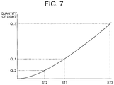
- a graph representing a difference of a quantity of light in the three states is shown in FIG. 7 .
- a quantity of light QL 1 in a first state ST 1 a quantity of light QL 2 in a second state ST 2 , and a quantity of light QL 3 in a third state ST 3 differ.
- the quantity of light increases for the state in an order of the second state ST 2 , the first state ST 1 , and the third state ST 3 .
- the position and the light flux diameter of the illumination light are set such that the illumination light passes through an inner side of the pupil of the objective lens and the range narrower than the pupil of the objective lens.
- the position and the light flux diameter of the illumination light may be set such that the illumination light passes through the entire range of the pupil of the objective lens.
- the aperture member may be disposed at a position of a conjugate image of the pupil of the objective lens.
- the position of the aperture member is not required to coincide perfectly with the position of the conjugate image or the pupil position of the objective lens.
- the aperture member is to be positioned near the pupil of the objective lens or near the conjugate image.
- the sample shape measuring method of the present embodiment even for a sample in which the reflectance of the surface is low and the surface shape is smooth, it is possible to measure the amount of tilt in the surface of the sample with high accuracy. Furthermore, it is possible to measure the surface shape of the sample with high accuracy by using the measured amount of tilt.
- the sample shape measuring method of the present embodiment includes a step of preparing illumination light passing through a predetermined illumination region, a step of applying the illumination light to a sample, and a predetermined processing step.
- the predetermined illumination region is set so as to include an optical axis at a pupil position of an illumination optical system.
- the illumination light is transmitted through the sample.
- Light transmitted through the sample is incident on an observation optical system.
- Light incident on the observation optical system passes through a transmission part that is set at a pupil position of the observation optical system or a transmission part that is set at a position of a conjugate image of a pupil of the observation optical system.
- the transmission part is set such that a part of light that reached the pupil of the observation optical system or a part of light that reached the conjugate image is transmitted through.
- the predetermined processing step includes a step of receiving the light emerged from the observation optical system, a step of obtaining a quantity of light of the received light, a step of calculating at least one of a difference and a ratio between the quantity of light and a reference quantity of light, and a step of calculating an amount of tilt in at a surface of the sample from at least one of the difference and the ratio.
- FIG. 8 is a flowchart of the measuring method of the present embodiment.
- the measuring method of the present embodiment includes step S 10 of preparing illumination light, step S 20 of applying the illumination light, and predetermined processing step S 30 .
- Predetermined processing step S 30 includes step S 31 of receiving imaging light, step S 32 of obtaining the quantity of light of the imaging light, step S 33 of calculating the difference or the ratio, and step S 34 of calculating the amount of tilt.
- step S 10 is executed.
- Step S 10 is a step of preparing the illumination light.
- a predetermined illumination region is set in an illumination optical system.
- the predetermined illumination region is a region where illumination light passes through.
- the predetermined illumination region is a region which is determined by the transmission part 4 b shown in FIG. 1 .
- the predetermined illumination region is set by disposing the stop 4 in the optical path of the illumination optical system 1 .
- the stop 4 is disposed so as to include the optical axis 10 . Accordingly, in the measuring method of the present embodiment, the bright field illumination is carried out.
- the stop 4 is disposed at the pupil position of the illumination optical system 1 , specifically, the pupil position of the condenser lens 5 .
- the position of the pupil of the condenser lens 5 is conjugate to the pupil position of the observation optical system 2 , specifically, the position of the pupil 7 of the objective lens. Therefore, an image of the predetermined illumination region is formed at the position of the pupil 7 of the objective lens.
- the image of the predetermined illumination region is formed only at an inner side of the pupil 7 of the objective lens.
- the image of the predetermined illumination region is formed such that an area of an image of the predetermined illumination region becomes smaller than an area of the pupil 7 of the objective lens.
- the image of the predetermined illumination region may be formed such that the area of the image of the predetermined illumination region becomes same as the area of the pupil 7 of the objective lens.
- the area of the image of the predetermined illumination region can be deemed as a light flux diameter of the illumination light at the position of the pupil 7 of the objective lens.
- a light intensity varies according to a movement of the illumination light. At this time, the light intensity varies in both of the direction of movement of the illumination light in a direction approaching the optical axis and the direction of movement of the illumination light in a direction away from the optical axis.
- the light intensity varies in a case of approaching the optical axis.
- the light intensity does not vary in the direction away from the optical axis.
- the predetermined illumination region 180 degrees around the optical axis, the light intensity varies even in the direction away from the optical axis.
- the predetermined illumination region is set so as to include the optical axis at the pupil position of the illumination optical system and is set such that the area of the illumination light becomes smaller than the area of the pupil at the pupil position of the observation optical system.
- the predetermined illumination region may be set such that the illumination light passes through the entire range of the pupil of the observation optical system.
- Step S 20 is a step of applying illumination light.
- illumination light is applied to a sample.
- the illumination light applied to the sample is transmitted through the sample.
- the sample is illuminated whereby imaging light emerges from the sample.
- the light transmitted through the sample is incident on the observation optical system.
- the light incident on the observation optical system passes through a transmission part that is set at the pupil position of the observation optical system.
- the transmission part is set such that a part of light that has reached the pupil of the observation optical system is transmitted through the transmission part.
- the transmission part may be set at a position conjugate with the pupil position of the observation optical system.
- step S 30 is executed.
- Step S 30 is a step of performing predetermined processing.
- step S 31 step S 32 , step S 33 , and step S 34 are executed.
- step S 30 first, step S 31 is executed.
- Step S 31 is a step of receiving imaging light.
- the imaging light is the light transmitted through the observation optical system.
- Step S 32 is a step of obtaining the quantity of light of the imaging light.
- the quantity of light of the imaging light is the quantity of light received in step S 31 .
- Step S 33 is a step of calculating the difference or the ratio.
- the difference or the ratio between the quantity of light received in step S 31 that is, the quantity of light of the imaging light and a reference quantity of light is calculated.
- step S 34 is executed.
- Step S 34 is a step of calculating the amount of tilt.
- the amount of tilt in the surface of the sample is calculated from the result of calculation in step S 33 .
- step S 33 at least one of the difference and the ratio between the quantity of light of the imaging light and the reference quantity of light is calculated.
- the illumination which is almost identical to the bright field illumination is carried out, and a part of the light that reached the pupil position of the observation optical system or a part of the light that reached the conjugate image of the pupil of the observation optical system is merely transmitted.
- the contrast of an image or the interference between non-diffracted light and diffracted light is not utilized. Therefore, according to the measuring method of the present embodiment, even for a sample in which the reflectance of the surface is low and the surface shape is smooth, it is possible to measure the amount of tilt in the surface of the sample with high accuracy. Furthermore, as will be described later, by using the measured amount of tilt, it is possible to measure the surface shape of the sample with high accuracy.
- the sample shape measuring apparatus of the present embodiment includes an illumination optical system, an observation optical system, a detecting element, and a processing apparatus.
- the illumination optical system includes a light source and a condenser lens.
- the observation optical system includes an objective lens, an aperture member, and an imaging lens.
- a sample is disposed between the illumination optical system and the observation optical system. Illumination light applied to the sample by the illumination optical system is transmitted through the sample. Light transmitted through the sample is incident on the observation optical system.
- the detecting element receives light emerged from the observation optical system.
- the processing apparatus obtains a quantity of light based on the received light, calculates at least one of a difference and a ratio between the quantity of light and a reference quantity of light, calculates an amount of tilt in a surface of the sample based on at least one of the difference and the ratio, and calculates a shape of the sample from the amount of tilt.
- FIG. 9 is a diagram illustrating a configuration of the sample shape measuring apparatus of the present embodiment.
- a sample shape measuring apparatus 20 is an upright microscope, for example, which includes an illumination optical system and an observation optical system.
- the illumination optical system includes alight source 21 , a condenser lens 24 , and a stop 25 .
- the illumination optical system includes a lens 22 and a lens 23 as needed.
- the objective optical system includes an objective lens 28 , an aperture member 30 , and an imaging lens 31 .
- the aperture member 30 is disposed at a position of a pupil 29 of the objective lens.
- the aperture member 30 corresponds to the aperture member 7 in FIG. 1 .
- the stop 25 is provided.
- the condenser lens 24 and the stop 25 are integrally configured.
- the stop 25 and the condenser lens 24 may be configured as separate bodies.
- a metal plate is used in the stop 25 .
- a condenser unit having a reflecting surface may be used.
- the condenser unit may include, for example, a conical mirror and a concave mirror.
- the conical mirror is disposed on the optical axis.
- the concave mirror has an annular reflecting surface and is disposed to surround the conical mirror.
- the stop 25 and the light source 21 are conjugate. Therefore, the illumination light emitted from the light source 21 is collected at the position of the stop 25 . That is, an image of the light source 21 is formed at the position of the stop 25 .
- Illumination light emerged from the opening of the stop 25 is incident on the condenser lens 24 .
- the position of the stop 25 coincides with a focal position of the condenser lens 24 (or the pupil position of the condenser lens 24 ). Therefore, illumination light emerged from the condenser lens 24 becomes parallel light.
- the stop 25 has a transmission part. As shown in FIG. 9 , the transmission part includes an optical axis 35 . Accordingly, in the sample shape measuring apparatus 20 , illumination almost identical to the bright field illumination is carried out.
- Illumination light emerged from the condenser lens 24 reaches a sample 27 .
- the sample 27 is placed on a holding member 26 .
- the sample 27 is a cell, for example, which is colorless and transparent.
- the holding member 26 has a holding part. In a slide glass, a surface of the slide glass corresponds to the holding part. In a petri dish, a concave portion of the petri dish corresponds to the holding part. In a micro-well plate, a concave portion of each well corresponds to the holding part.
- the light passing through the sample 27 i.e., imaging light enters a microscope objective lens 28 (hereinafter, referred to as an “objective lens”).
- the objective lens 28 is a microscope objective lens for bright-field observation, for example. Therefore, only a lens is present in the optical path of the objective lens 28 , and no optical member to change the intensity or the phase of light, such as a phase plate or a modulation plate, is not present in the optical path.
- the stop 25 has the transmission part.
- the illumination light passes through the transmission part. Accordingly, the image of the stop 25 formed at the position of the pupil 29 of the objective lens becomes an image of the illumination light.
- illumination light that has passed near an edge of the transmission part passes an inner side of the pupil 29 of the objective lens and through a range narrower than the pupil 29 of the objective lens.
- the position of the transmission part is set such that the illumination light is positioned at the inner side of the pupil at the position of the pupil 29 of the objective lens. Therefore, when the transmission part is projected on the position of the pupil 29 of the objective lens, an image of the transmission part is formed only on the inner side of the pupil 29 of the objective lens, and is not formed on an outer side of the pupil 29 of the objective lens.
- the aperture member 30 is disposed at the position of the pupil 29 of the objective lens.
- FIG. 9 for indicating clearly the position of the pupil 29 of the objective lens, the pupil 29 of the objective lens and the aperture member 30 are drawn separately.
- the aperture member 30 a light-shielding part and a transmission part are provided.
- the transmission part is set such that a part of light that reached the pupil of the observation optical system is transmitted through.
- the pupil position of the observation optical system is the position of the pupil 29 of the objective lens. The specific structure of the aperture member 30 will be described later.
- the imaging light emerged from the objective lens 28 enters the imaging lens 31 . Then, an optical image of the sample 27 is formed at an image position 32 by the imaging light emerged from the imaging lens 31 .
- a detecting element 33 is disposed at the image position 32 .
- the detecting element 33 is a photoelectric conversion element. Examples of the detecting element 33 include photodiode, CCD, and COMS.
- the light intensity of an optical image is converted by the detecting element 33 into an electric signal.
- the converted electric signal is transmitted as image data of the sample 27 to the processing apparatus 34 .
- the image data represents the quantity of light of the optical image.
- processing is executed in accordance with the flowchart shown in FIG. 8 . That is, in the processing apparatus 34 , the quantity of light of the imaging light is obtained (step S 32 ), the difference or the ratio between the quantity of light and the reference quantity of light is calculated (step S 33 ), and the amount of tilt in the surface of the sample is calculated from the calculation result (step S 34 ).
- FIG. 10 is a diagram illustrating another sample shape measuring apparatus.
- the illumination optical system is omitted.
- the aperture member 30 is disposed at a position of a conjugate image 36 of the pupil 29 of the objective lens (hereinafter, referred to as ‘conjugate image 36 ’).
- conjugate image 36 the position of the conjugate image 36 and the aperture member 30 are drawn separately.
- the aperture member 30 has to be disposed at the interior of the objective lens 28 .
- the aperture member 30 can be disposed at the interior of the objective lens 28 without any difficulty.
- a lens 37 is disposed between the imaging lens 31 and the image position 32 . Accordingly, the conjugate image 36 is formed at an exterior of the objective lens 28 . Therefore, it is not indispensable to provide the aperture member 30 at the interior of the objective lens 28 . As a result, it is possible to use an objective lens for bright-field observation as it is, in the sample shape measuring apparatus of the present embodiment.
- a lens 38 is disposed between the lens 37 and the detecting element 33 . Accordingly, a part of light that reached the conjugate image 36 is detected by the detecting element 33 .
- FIG. 11A is a diagram illustrating an aperture member of a illustrative embodiment 1
- FIG. 11B is a diagram illustrating an arrangement of the aperture member of the illustrative embodiment 1.
- An aperture member 40 of the illustrative embodiment 1 has a light-shielding part 40 a and a transmission part 40 b .
- a shape of the aperture member 40 is a shape of a portion cut out from a circular-shaped member. The cut-out portion is the transmission part 40 b .
- a shape of the light-shielding part 40 a is an bow-shaped.
- An incident position of imaging light L SP1 relative to the objective lens 28 varies according to the amount of tilt in the surface of the sample. Due to the variation, a quantity of light of imaging light L SP3 that passes through the transmission part 40 b varies.
- a graph showing the variation in the quantity of light at the aperture member of the illustrative embodiment 1 is shown in FIG. 12 .
- a curve indicating a relationship of the quantity of light and ⁇ v/2r hereinafter, referred to as ‘characteristic curve’) is shown.
- a horizontal axis of the graph indicates an amount of shift in the incident position of imaging light L SP1 relative to the objective lens 28 .
- the amount of shift is obtained from ⁇ V which is a difference between a center of imaging light L SP3 and the optical axis 35 .
- a shape of imaging light L SP3 is assumed to be a circle.
- ⁇ V is normalized by 2r.
- r denotes a radius when imaging light L SP3 is assumed to be a circle.
- an area of the transmission part 40 b is extremely large as compared to an area of the light-shielding part 40 a .
- FIG. 13A is a diagram illustrating an aperture member of an illustrative embodiment 2
- FIG. 13B is a diagram illustrating an arrangement of the aperture member of the illustrative embodiment 2.
- An aperture member 41 of the illustrative embodiment 2 has a light-shielding part 41 a and a transmission part 41 b .
- a shape of the aperture member 41 is a shape of a portion cut out from a circular-shaped member. The cut-out portion is the transmission part 41 b .
- a shape of the transmission part 41 b is an bow-shaped.
- FIG. 14 A graph showing a variation in the quantity of light at the aperture member of the illustrative embodiment 2 is shown in FIG. 14 .
- an area of the transmission part 41 b is extremely small as compared to an area of the light-shielding part 41 a .
- FIG. 15A is a diagram illustrating an aperture member of a illustrative embodiment 3
- FIG. 15B is a diagram illustrating an arrangement of the aperture member of the illustrative embodiment 3.
- An aperture member 42 of the illustrative embodiment 3 has a light-shielding part 42 a and a transmission part 42 b .
- a shape of the aperture member 42 is a circular shape, and a diameter of the circle is smaller than a diameter of the pupil 29 of the objective lens.
- a circular-shaped portion is the light-shielding part 42 a.
- the illumination which is almost identical to the bright field illumination is carried out, and a part of the light that reached the pupil of the observation optical system or apart of the light that reached the conjugate image of the pupil of the observation optical system is merely transmitted.
- the contrast of an image or the interference between non-diffracted light and diffracted light is not utilized. Therefore, according to the sample measuring apparatus of the present embodiment, even for a sample in which the reflectance of the surface is low and the surface shape is smooth, it is possible to measure the amount of tilt in the surface of the sample with high accuracy. Furthermore, as will be described later, by using the measured amount of tilt, it is possible to measure the surface shape of the sample with high accuracy.
- the aperture member have a light-shielding part and a transmission part, the light-shielding part be provided so as to include the optical axis of the objective lens, and the transmission part be provided so as to include an outer side and a part of an inner side of an image of a pupil of the illumination optical system.
- the aperture member 41 has the light-shielding part 41 a and the transmission part 41 b .
- the light-shielding part 41 a is provided so as to include the optical axis 35 .
- the transmission part 41 b is provided so as to include a part of the outer side and a part of the inner side of the pupil of the illumination optical system.
- the aperture member 42 has the light-shielding part 42 a and the transmission part 42 b .
- the light-shielding part 42 a is provided so as to include the optical axis 35 .
- the transmission part 42 b is provided so as to include an entire outer side and a part of the inner side of the image of the pupil of the illumination optical system.
- the transmission part is provided so as to include at least a part of the outer side and a part of the inner side of the image of the pupil of the illumination optical system.
- the aperture member 41 or the aperture member 42 By using the aperture member 41 or the aperture member 42 , even for a sample in which the reflectance of the surface is low and the surface shape is smooth, it is possible to measure the amount of tilt in the surface of the sample with high accuracy. Furthermore, by using the measured amount of tilt, it is possible to measure the surface shape of the sample with high accuracy.
- the aperture member have a light-shielding part and a transmission part, the light-shielding part be provided so as to include an optical axis of the objective lens, and the transmission part be eccentric with respect to the optical axis, and be provided so as to include a part of an edge of an image of a pupil of the illumination optical system.
- the aperture member 41 has the light-shielding part 41 a and the transmission part 41 b .
- the light-shielding part 41 a is provided so as to include the optical axis 35 .
- the transmission part 41 b is provided at a position eccentric with respect to the optical axis 35 .
- the transmission part 41 b is provided so as to include the outer side and a part of the inner side of the image of the pupil of the illumination optical system.
- the aperture member 41 By using the aperture member 41 , even for a sample in which the reflectance of the surface is low and the surface shape is smooth, it is possible to measure the amount of tilt in the surface of the sample with high accuracy. Furthermore, by using the measured amount of tilt, it is possible to measure the surface shape of the sample with high accuracy.
- the aperture member have a light-shielding part and a transmission part, the light-shielding part be provided so as to include an optical axis of the objective lens, and the transmission part be provided so as not to include the optical axis but to include an entire edge of an image of a pupil of the illumination optical system.
- the aperture member 42 includes the light-shielding part 42 a and the transmission part 42 b .
- the light-shielding part 42 a is provided so as to include the optical axis 35 .
- the transmission part 42 b is provided at a position not including the optical axis.
- the transmission part 42 b is provided so as to include the entire edge of the image of the pupil of the illumination optical system.
- the aperture member 42 By using the aperture member 42 , even for a sample in which the reflectance of the surface is low and the surface shape is smooth, it is possible to measure the amount of tilt in the surface of the sample with high accuracy. Furthermore, by using the measured amount of tilt, it is possible to measure the surface shape of the sample with high accuracy.
- R0 denotes a length from the optical axis of the objective lens up to a predetermined position
- R1 denotes a length from the optical axis of the objective lens up to an outer edge of the transmission part, and denotes a length on a line connecting the optical axis of the objective lens and the predetermined position, and here
- the predetermined position is a position at which a length from the optical axis of the objective lens is the minimum, from among positions on an inner edge of the light-shielding part,
- Rill denotes a radius of the pupil of the illumination optical system
- ⁇ denotes a value obtained by dividing a focal length of the objective lens by a focal length of the condenser lens.
- the transmission part of the aperture member is positioned at the inner side of the pupil of the observation optical system.
- the edge of the image of the pupil of the illumination optical system is included in the transmission part. This signifies that the edge of the image of the pupil of the illumination optical system is positioned at the inner side of the pupil of the observation optical system.
- the sample shape measuring apparatus of the present embodiment it is possible to use an optical system of a microscope.
- a microscope objective lens is used as the observation optical system
- a condenser lens is used as the illumination optical system.
- a size of the image of the pupil of the illumination optical system is determined by the numerical aperture of the illumination optical system and the numerical aperture of the observation optical system. Therefore, according to a combination of the illumination optical system and the observation optical system, there is a possibility that the image of the pupil of the illumination optical system is larger than the pupil of the observation optical system. In this case, the edge of the image of the pupil of the illumination optical system is not positioned at the inner side of the pupil of the observation optical system.
- a light flux diameter of light emitted from the light source 21 is made thin.
- the light flux diameter of the illumination light is included in the transmission part. Since a position of the light flux of the illumination light varies in accordance with the amount of tilt in the surface of the sample, it is possible to detect the variation in the amount of tilt in the surface of the sample as a variation in brightness.
- the transmission part includes the outer side and a part of the inner side of the image of the pupil of the illumination optical system’ can be put in another way as ‘the transmission part includes the outer side and a part of the inner side of a light flux of the illumination light at the pupil position of the observation optical system’.
- the transmission part includes a part of the edge of the image of the pupil of the illumination optical system’ can be put in another way as ‘the transmission part includes a part of the edge of a light flux of the illumination light at the pupil position of the observation optical system’.
- the transmission part is provided so as to include the entire edge of the image of the pupil of the illumination optical system’ can be put in another way as ‘the transmission part is provided so as to include the entire light flux of the illumination light at the pupil position of the observation optical system’.
- ‘Rill denotes the radius of the pupil of the illumination optical system’ can be put in another way as ‘Rill denotes a radius of a light flux of the illumination light at the pupil position of the observation optical system’.
- the aperture member have a boundary line dividing the light-shielding part and the transmission part, and the boundary line be formed of a line parallel to one straight line orthogonal to the optical axis.
- FIG. 16 is a diagram illustrating an example of the aperture member.
- the aperture member 50 has a light-shielding part 50 a and a transmission part 50 b .
- a shape of the aperture member 50 is a shape of a portion cut out from a circular-shaped member. The cut-out portion is the transmission part 50 b.
- a boundary line 51 is formed between the light-shielding part 50 a and the transmission part 50 b .
- the light-shielding part 50 a and the transmission part 50 b are divided by the boundary line 51 .
- the boundary line 51 is a line parallel with a straight line orthogonal to the optical axis 35 .
- the aperture member have a boundary line dividing the light-shielding part and the transmission part, and a straight line connecting predetermined two points be located between the boundary line and the optical axis.
- the predetermined two points are two points at which a predetermined line crosses the outer edge of the pupil of the illumination optical system when the pupil of the illumination optical system is superimposed on the aperture member.
- FIG. 17 is a diagram illustrating another example of the aperture member.
- the aperture member 60 includes a light-shielding part 60 a and a transmission part 60 b .
- a shape of the aperture member 50 is a shape of a portion cut out from a circular-shaped member. The cut-out portion is the transmission part 60 b.
- a boundary line 61 is formed between the light-shielding part 60 a and the transmission part 60 b .
- the light-shielding part 60 a and the transmission part 60 b are divided by the boundary line 61 .
- a straight line 64 is a straight line (predetermined line) running through the point 62 and the point 63 .
- the boundary line 61 is formed of an arc.
- the arc is formed to project from the light-shielding part 60 a toward the transmission part 60 b . Accordingly, in the aperture member 60 , the straight line 64 is positioned between the boundary line 61 and the optical axis 35 .
- the boundary line 61 is a line formed of a curve.
- the boundary line 61 may be any of a line formed of a plurality of straight lines, a line formed of a plurality of curves, and a line formed of a curve and a straight line.
- the aperture member have a boundary line dividing the light-shielding part and the transmission part, and the boundary line be located between a straight line connecting predetermined two points and the optical axis.
- the predetermined two points are two points at which a predetermined line crosses the outer edge of the pupil of the illumination optical system when the pupil of the illumination optical system is superimposed on the aperture member.
- FIG. 18 is a diagram illustrating another example of the aperture member.
- the aperture member 70 includes a light-shielding part 70 a and a transmission part 70 b .
- a shape of the aperture member 70 is a shape of a portion cut out from a circular-shaped member. The cut-out portion is the transmission part 70 b.
- a boundary line 71 is formed between the light-shielding part 70 a and the transmission part 70 b .
- the light-shielding part 70 a and the transmission part 70 b are divided by the boundary line 71 .
- the boundary line 71 and the outer edge of the pupil 29 of the objective lens cross at a point 72 and a point 73 .
- the point 72 and the point 73 are the predetermined two points.
- a straight line 74 is a straight line (predetermined line) passing through the point 72 and the point 73 .
- the boundary line 71 is formed of an arc.
- the arc is formed to project from the transmission part 70 b toward the light-shielding part 70 a . Accordingly, in the aperture member 70 , the boundary line 71 is positioned between the straight line 74 and the optical axis 35 .
- the boundary line 71 is a line formed of a curve.
- the boundary line 71 may be any of a line formed of a plurality of straight lines, a line formed of a plurality of curves, and a line formed of a curve and a straight line.
- the illumination optical system have a predetermined illumination region, a surface light source be disposed or an image of the surface light source be formed on the predetermined illumination region, and light emerged from the observation optical system be received.
- FIG. 19 shows a state of illumination light.
- a surface light source 80 is disposed on a predetermined illumination region.
- the predetermined illumination region is a transmission part of the stop 25 .
- illumination light emerged from a partial region (hereinafter, referred to as ‘region A’) positioned on one side of the surface light source 80 is shown.
- the illumination light emerged from one end of the region A is indicated by dotted lines, and illumination light emerged from the other end of the region A is indicated by dashed lines.
- the transmission part of the stop 25 includes the optical axis. Accordingly, the surface light source 80 is disposed in a circular-shaped region including the optical axis.
- the illumination light indicated by the dotted lines and the illumination light indicated by the dashed lines are both emerged as parallel light flux from the condenser lens 24 . Accordingly, the sample 27 is illuminated by illumination light which is spread.
- illumination light similar to the region A is emitted also from the other side of the planar light source 80 .
- the illumination light emitted from the other side is emerged as a parallel light flux from the condenser lens 24 .
- the illumination light emitted from the other side as well is applied to the sample 27 .
- Imaging light is transmitted through the sample 27 which is illuminated.
- imaging light directed in a particular direction from a point P 1 and a point P 2 of the sample 27 are indicated by solid lines and alternate long and two short dashes lines.
- imaging lights directed in various directions are emerged from the point P 1 and the point P 2 of the sample 27 .
- FIG. 20 For instance, a state of imaging light directed in various directions emerging from a point P 3 is shown in FIG. 20 . Imaging light directed in various directions is emerged from the point P 1 and the point P 2 , similarly as the imaging light emerged from the point P 3 .
- a part of the imaging light emerged from the point P 1 of the sample 27 is shielded at the light-shielding part of the aperture member 41 .
- a part of the imaging light emerged from the point P 2 of the sample is also shielded at the light-shielding part of the aperture member 41 .
- the remaining of the imaging light emerged from the point P 1 of the sample 27 is focused at an image position by the objective lens 28 and the imaging lens 31 .
- An image P 1 ′ of the point P 1 is formed at the image position.
- the remaining of the imaging light emerged from the point P 2 of the sample 27 is also focused at an image position by the objective lens 28 and the imaging lens 31 .
- An image P 2 ′ of the point P 2 is formed at the image position. In such manner, a two-dimensional image is formed at the image position.
- imaging light is received at a plurality of micro regions.
- the micro regions are arranged in rows two-dimensionally. Accordingly, the two-dimensional image is divided into the plurality of micro regions. Light is received at each micro region. As a result, it is possible to measure the shape of the surface of the sample over a wide range at one time.
- the illumination light which passes through the predetermined illumination region be a parallel light flux.
- FIG. 20 is a diagram illustrating a state of the illumination light.
- a parallel light flux is applied to the stop 25 . Accordingly, illumination light which passes through the predetermined illumination region also becomes a parallel light flux.
- the transmission part of the stop 25 includes the optical axis. Accordingly, the parallel light flux passes through a circular-shaped region including the optical axis.
- the illumination light is incident on the condenser lens 24 .
- the illumination light incident on the condenser lens 24 is focused at a position of the sample 27 . Accordingly, the sample 27 is illuminated by illumination light in the form a point.
- Imaging light emerges from the sample 27 that is illuminated. A part of the imaging light emerged from the point P 3 of the sample 27 is shielded by the light-shielding part of the aperture member 41 . Whereas, the remaining of the imaging light emerged from the point P 3 of the sample 27 is focused at an image position by the objective lens 28 and the imaging lens 31 . An image P 3 ′ of the point P 3 is formed at the image position.
- the illumination light passing through the predetermined illumination region is a parallel light flux
- the illumination light is applied only to one point of the sample 27 .
- the imaging light is also the only light from one point of the sample 27 . Consequently, when step S 30 is executed, only an amount of tilt at one point of the sample 27 is calculated.
- the illumination light that passes through the predetermined illumination region is a parallel light flux
- the illumination light passing through the predetermined illumination region is a parallel light flux
- no amount of tilt except at only one point of the sample 27 is calculated.
- the illumination light and the sample are to be moved relatively in a plane orthogonal to the optical axis. In such manner, it is possible to calculate the amount of tilt at the plurality of positions of the sample 27 .
- the sample shape measuring apparatus include a first aperture member and a second aperture member that are inserted into and removed from an optical path.
- the first aperture member has a light-shielding part at a location including an optical axis of the objective lens and a first transmission part at a position eccentric with respect to the optical axis.
- the second aperture member has a light-shielding part at a location including an optical axis of the objective lens and a second transmission part at a position eccentric with respect to the optical axis.
- FIG. 21 is a diagram illustrating a structure of another sample shape measuring apparatus of the present embodiment. Same reference numerals are assigned to components identical to those in FIG. 10 , and description thereof is omitted.
- a sample shape measuring apparatus 90 includes a first aperture member 91 and a second aperture member 92 .
- a transparent plate is used for the first aperture member 91 and the second aperture member 92 .
- Both the first aperture member 91 and the second aperture member 92 are held by a moving mechanism 93 .
- a slider and a turret are available as the moving mechanism 93 , for example.
- the moving mechanism 93 is a slider
- the first aperture member 91 and the second aperture member 92 move in a direction orthogonal to the optical axis 35 .
- the moving mechanism 93 is a turret
- the first aperture member 91 and the second aperture member 92 rotate around an axis parallel to the optical axis 35 as a center.
- FIG. 22A is a diagram illustrating a state in which a first aperture member is inserted into an optical path.
- FIG. 22B is a diagram illustrating a state in which a second aperture member is inserted into an optical path.
- the first aperture member 91 has a light-shielding part 91 a and a first transmission part 91 b .
- a location including the optical axis 35 is the light-shielding part 91 a .
- the first aperture member 91 has the first transmission part 91 b at a position eccentric with respect to the optical axis 35 .
- the second aperture member 92 has a light-shielding part 92 a and a second transmission part 92 b .
- a location including the optical axis 35 is the light-shielding part 92 a .
- the second aperture member 92 has the second transmission part 92 b at a position eccentric with respect to the optical axis 35 .
- a direction connecting the optical axis 35 and a center of gravity of the first transmission part 91 b and a direction connecting the optical axis 35 and a center of gravity of the second transmission part 92 b intersect when the first aperture member 91 is inserted into the optical path and when the second aperture member 92 is inserted into the optical path.
- the first transmission part 91 b is positioned on one straight line of two straight lines that are orthogonal, and the second transmission part 92 b is positioned on the other straight line.
- An area of illumination light passing through the first transmission part 91 b is equal to an area of illumination light passing through the second transmission part 92 b . Accordingly, variation in the area of the illumination light when the inclination angle of the sample is varied, is same when the first aperture member 91 is inserted into the optical path and when the second aperture member 92 is inserted into the optical path.
- a spectral transmittance characteristic at the first transmission part 91 b is identical to a spectral transmittance characteristic at the second transmission part 92 b .
- a wavelength band of light emitted from the light source may be wide or may be narrow.
- the spectral transmittance characteristic at the first transmission part 91 b may differentiate from the spectral transmittance characteristic at the second transmission part 92 b .
- a method of carrying out the measurement without changing a wavelength of the illumination light and a method of carrying out the measurement by changing the wavelength of the illumination light are available.
- a light source in which a wavelength band of emitted light is wide is used as a light source.
- a white light source is available.
- a detecting element a plurality of photoelectric conversion elements is used.
- a detecting element which includes the plurality of photoelectric conversion elements a three-plate type camera is available, for example.
- the three-plate type camera includes three CCDs.
- a filter of red color is disposed in a first CCD
- a filter of green color is disposed in a second CCD
- a filter of blue color is disposed in a third CCD.
- the spectral transmittance characteristic at the first transmission part 91 b is matched with spectral transmittance characteristic of the filter of red color and the spectral transmittance characteristic at the second transmission part 92 b is matched with spectral transmittance characteristic of the filter of green color.
- the white light source is disposed in the optical path, and the measurement is carried out by the first CCD when the first aperture member 91 is inserted into the optical path and the measurement is carried out by the second CCD when the second aperture member 92 is inserted into the optical path.
- a second light source is prepared in addition to a first light source. Moreover, a wavelength band of light emitted from the first light source and a wavelength band of light emitted from the second light source are differentiated. Furthermore, a spectral transmittance characteristic at the first transmission part is matched with the wavelength band of the light emitted from the first light source and a spectral transmittance characteristic at the second transmission part 92 b is matched with the wavelength of the light emitted from the second light source.
- the measurement when the first aperture member 91 is inserted into the optical path, the measurement is carried out by using the first light source and when the second aperture member 92 is inserted into the optical path, the measurement is carried out by using the second light source.
- a plurality of optical filters is prepared. For instance, a first optical filter and a second optical filter are prepared. Moreover, the spectral transmittance characteristic at the first transmission part 91 b is matched with a spectral transmittance characteristic of the first optical filter and the spectral transmittance characteristic at the second transmission part 92 b is matched with spectral characteristic of the second optical filter.
- the measurement when the first aperture member 91 is inserted into the optical path, the measurement is carried out by using the first optical filter and when the second aperture member 92 is inserted into the optical path, the measurement is carried out by using the second optical filter.
- the sample shape measuring apparatus of the present embodiment it is possible to detect a variation of the quantity of light of the imaging light in any direction. Therefore, according to the sample shape measuring apparatus of the present embodiment, it is possible to calculate a direction of inclination and the amount of tilt in the surface of the sample.
- the aperture member have a light-shielding part at a location including an optical axis of the objective lens, and a first transmission part and a second transmission part at positions eccentric with respect to the optical axis.
- a direction connecting the optical axis and a center of gravity of the first transmission part and a direction connecting the optical axis and a center of gravity of the second transmission part intersect.
- FIG. 23 is a diagram illustrating a state in which the aperture member is inserted into the optical path.
- An aperture member 100 has a light-shielding part 100 a , a first transmission part 100 b , and a second transmission part 100 c .
- a location including the optical axis 35 is the light-shielding part 100 a .
- the aperture member 100 has the first transmission part 100 b and the second transmission part 100 c at positions eccentric with respect to the optical axis 35 .
- a direction connecting the optical axis 35 and a center of gravity of the transmission part 100 b and a direction connecting the optical axis 35 and a center of gravity of the second transmission part 100 c intersect.
- the first transmission part 100 b is positioned on one straight line of two straight lines that are orthogonal, and the second transmission part 100 c is positioned on the other straight line.
- An area of illumination light passing through the first transmission part 100 b is equal to an area of illumination light passing through the second transmission part 100 c . Accordingly, variation in the area S when an inclination angle ⁇ s is varied, is same when the illumination light is transmitted through the first transmission part 100 b and when the illumination light is transmitted through the second transmission part 100 c.
- the sample shape measuring apparatus of the present embodiment it is possible to detect a variation of the quantity of light of the imaging light in any direction without moving the aperture member. Therefore, according to the sample shape measuring apparatus of the present embodiment, it is possible to calculate the direction of inclination and the amount of tilt in the surface of the sample.
- the aperture member have a light-shielding part at a location including an optical axis of the objective lens and a transmission part at a position eccentric with respect to the optical axis, and a direction connecting the optical axis and a center of gravity of the transmission part be variable.
- FIG. 24 is a diagram illustrating a state in which the aperture member is inserted into the optical path.
- An aperture member 110 has a light-shielding part 110 a .
- a location including the optical axis 35 is the light-shielding part 110 a .
- the aperture member 110 has a transmission part 100 b at a position eccentric with respect to the optical axis 35 .
- the aperture member 110 is rotatable from a position indicated by solid lines to a position indicated by alternate long and short dash lines.
- the direction connecting the optical axis and the center of gravity of the transmission part is variable.
- the sample shape measuring apparatus of the present embodiment it is possible to detect a variation of the quantity of light of the imaging light in any direction. Therefore, according to the sample state measuring apparatus of the present embodiment, it is possible to calculate the direction of inclination and the amount of tilt in the surface of the sample.
- At least one of a size of the light-shielding part and a numerical aperture on a sample side of the objective lens be variable.
- FIG. 25A is a diagram illustrating a state when the quantity of light is zero. In this state, the whole of the imaging light is shielded by the light-shielding part 41 a as shown in FIG. 25A . Consequently, in this case, since there is no light flux that passes through the pupil 29 of the objective lens, it is not possible to measure the amount of tilt.
- FIG. 25B is a diagram illustrating a state in which the aperture member is replaced.
- An aperture member 120 has a light-shielding part 120 a and a transmission part 120 b .
- a size of the light-shielding part 120 a is smaller than a size of the light-shielding part 41 a .
- a size of the transmission part 120 b is larger than a size of the transmission part 41 b.
- the aperture member 41 is to be replaced with the aperture member 120 , without replacing the objective lens.
- imaging light L SP3 reaches the transmission part 120 b .
- a state in which imaging light L SP3 emerges from the aperture member 120 is realized.
- the aperture member 41 is disposed at the pupil position of the objective lens. In a case in which the pupil of the objective lens is positioned at the interior of the objective lens, the aperture member 41 is also disposed at the interior of the objective lens. Even in such state, the replacement may be carried out when it is possible to replace the aperture member 41 with the aperture member 120 . In a case in which it is difficult to replace the aperture member 41 with the aperture member 120 , the replacement of the aperture member 41 and the aperture member 120 may be carried out at the position of the conjugate image of the pupil of the objective lens.
- FIG. 25C is a diagram illustrating a state in which the objective lens is replaced.
- an objective lens A to be the objective lens having the aperture member 41
- an objective lens B to be an objective lens having an aperture member 130 .
- the numerical aperture on the sample side differs for the objective lens A and the objective lens B.
- the aperture member 130 has a light-shielding part 130 a and a transmission part 130 b .
- a size of the light-shielding part 130 a differs from a size of the light-shielding part 41 a .
- a size of the transmission part 130 b differs from a size of the transmission part 41 b.
- the numerical aperture on the sample side differs for the objective lens A and the objective lens B. Consequently, a diameter of a pupil 140 of the objective lens A differs from a diameter of the pupil 29 of the objective lens B. Moreover, a size of the imaging light at a pupil position of the objective lens also differs for the objective lens A and the objective lens B.
- imaging light L SP3 reaches the transmission part 130 b .
- a state in which imaging light L SP3 emerges from the aperture member 130 is realized.
- a change in a numerical aperture on a sample side of the objective lens be carried out by one objective lens.
- a zoom objective lens may be used for changing the numerical aperture on the sample side of the objective lens.
- an arrangement is to be made such that the numerical aperture on sample side varies according to a variation in magnification.
- a liquid crystal may be disposed at the pupil position of the objective lens, and the numerical aperture on sample side of the objective lens may be changed by varying the transmitting region.
- a change in a numerical aperture on a sample side of the objective lens be carried out by switching a plurality of objective lenses.
- a pupil magnification be a ratio of a diameter of a pupil in the illumination optical system and a diameter of a pupil in the observation optical system, a variation in the pupil magnification occur according to a sample, and a step of correcting an error which occurs due to the variation in the pupil magnification be provided.
- FIG. 26 is a flowchart of a measuring method of the present embodiment. Same reference numerals are assigned to steps that are same as in the flowchart in FIG. 8 , and the description thereof is omitted.
- the sample shape measuring apparatus of the present embodiment has step S 90 of correcting an error.
- step S 90 is executed.
- Step S 90 is a step of correcting the error which occurs due to the variation in the pupil magnification.
- the pupil magnification is a ratio of a diameter of the pupil in the illumination optical system and a diameter of the pupil in the observation optical system. The variation in the pupil magnification occurs according to a sample.
- FIG. 27A is a diagram illustrating an optical system in a case in which an area of a holding part is small.
- the description will be made by replacing the illumination optical system with the condenser lens 24 and by replacing the observation optical system with the objective lens 28 .
- a pupil 150 of the condenser lens and a pupil 151 of the objective lens are conjugate.
- the pupil magnification is determined by a ratio of a diameter of the pupil 150 and a diameter of the pupil 151 .
- the observation is carried out in a state in which the cell 152 is held by a holding part 154 in a liquid 153 such as a culture solution or a preservative solution.
- a liquid 153 such as a culture solution or a preservative solution.
- a sample part 155 can be deemed as a plane parallel plate. Accordingly, in the case in which the area of the holding part 154 is large, a state in which a plane parallel plate is disposed between the condenser lens 45 and the objective lens 28 is assumed.
- f ob denotes a focal length of the objective lens
- f c denotes a focal length of the condenser lens.
- FIG. 27B is a diagram illustrating an optical system when the sample part is replaced with the planoconcave lens. As shown in FIG. 27B , in the case in which the area of the holding part 154 is small, it becomes a state such that planoconcave lens 156 is disposed between the condenser lens 24 and the objective lens 28 .
- a focal length of the planoconcave lens 156 is determined by a radius of curvature at a concave surface of the liquid 153 and a refractive index of the liquid 153 . Moreover, since the liquid 153 has an affinity for water similar to water, the smaller the area of the holding part 154 is, the smaller the radius of curvature of the concave surface is. Consequently, in a microwell plate having a plurality of the holding parts 154 , the radius of curvature of the concave surface is extremely small.
- f len denotes a focal length of the planoconcave lens
- f ob denotes a focal length of the objective lens
- d denotes a distance between the objective lens and the planoconcave lens.
- a magnification of an optical system composed of the condenser lens 24 , the planoconcave lens 156 , and the objective lens 28 represents the ratio of the diameter of the pupil 150 and the diameter of the pupil 151 . Accordingly, a pupil magnification ⁇ p′ is expressed by the following expression (C):
- the objective lens 28 and the planoconcave lens 156 are deemed as thin lenses, a thickness of lenses is negligible. If so, the distance d becomes a distance between a principal point of the objective lens 28 and a principal point of the planoconcave lens 156 .
- f ob ⁇ d holds.
- the concave surface of the liquid 153 has a negative refractive power, f len ⁇ 0 holds. That is, ((f ob ⁇ d)/f len )>0 holds.
- the pupil magnification varies even in an upright microscope.
- the pupil magnification ⁇ p ′ becomes larger as compared to the pupil magnification ⁇ p .
- the variation in the pupil magnification occurs due to an effect of the negative refractive power of the planoconcave lens 156 , or in other words, due to the sample.
- the quantity of light of the imaging light that passes through the pupil 151 of the objective lens varies. Since this variation in quantity of light is not occurred due to the tilt in the surface of the sample, it becomes a measurement error.
- the focal length of the planoconcave lens 156 is necessary.
- the focal length of the planoconcave lens 156 is determined by the radius of curvature at the concave surface of the liquid 153 and the refractive index of the liquid 153 . Out of these, it is difficult to obtain the radius of curvature at the concave surface of the liquid 153 . Consequently, it is not easy to obtain the focal length of the planoconcave lens 156 . Therefore, it is difficult to obtain the pupil magnification ⁇ p ′ by using expression (C).
- the pupil magnification ⁇ p ′ can be obtained by another method.
- information of the pupil of the objective lens can be obtained from a state in which no sample is present and a state in which culture solution alone is present.
- the information of the pupil of the objective lens can be obtained, for example, using a Bertrand lens.
- the state in which no sample is present is a state in which the sample part 155 itself is not there.
- the state in the culture solution is present is a state in which the liquid 153 alone is present in the sample part 155 .
- the light flux is a parallel light flux between the objective lens and the imaging lens.
- the Bertrand lens is disposed between the objective lens and the imaging lens. Accordingly, it is possible to form an image of the pupil of the objective lens at an image position formed by the objective lens and the imaging lens.
- FIG. 28A is a diagram illustrating a state of a pupil of an objective lens and an imaging light in a state in which no sample is present.
- FIG. 28B is a diagram showing a state of the pupil of the objective lens and the imaging light in a state in which culture solution alone is present.
- a position of a boundary between a imaging light 157 and a light-shielding part 158 differs between the state in which no sample is present and the state in which culture solution alone is present. Then, by using the difference in position of the boundary, it is possible to obtain the pupil magnification ⁇ p ′.
- LA denotes a distance from the optical axis up to a predetermined boundary in the state in which no sample is present
- LB denotes a distance from the optical axis up to the predetermined boundary in the state in which the culture solution alone is present, and here
- the predetermined boundary is a boundary between the imaging light and the light-shielding part.
- the sample shape measuring apparatus have a holding member and a transparent plane parallel plate, and the holding member have a holding part which holds a liquid, and the transparent plane parallel plate be disposed in contact with a liquid surface of the liquid.
- a sample is held by the holding member.
- the sample is held together with the liquid by the holding member.
- the holding member in order to hold the liquid, has a holding part.
- FIG. 29A is a diagram illustrating a state of a liquid when a plane parallel plate is not disposed.
- FIG. 29B is a diagram illustrating a state of a liquid when a plane parallel plate is disposed.
- a holding member 160 has a holding part 161 .
- the holding part 161 is a space surrounded by a transparent side surface 160 a and a transparent bottom surface 160 b .
- a liquid 162 is held in the holding part 161 .
- a liquid surface 163 becomes a concave surface.
- the liquid 162 acts as a negative lens. Consequently, a parallel light flux 164 incident on the liquid 162 becomes a divergent light flux 165 and is emerged from the bottom surface 160 b , as shown by solid lines.
- the liquid surface 163 becomes a flat surface (not shown in the diagram).
- the liquid 162 can be deemed as a plane parallel plate, an effect as a lens does not occur in the liquid 162 . Consequently, the parallel light flux 164 incident on the liquid 162 becomes a parallel light flux 166 and is emerged from the bottom surface 160 b , as shown by dashed lines.
- the area of the light flux transmission region becomes a region of the imaging light 157 shown in FIG. 28A .
- the area of the light flux transmission region becomes a region of the imaging light 157 shown in FIG. 28B .
- a shape of the light flux emerging from the bottom surface 160 varies in accordance with the amount of tilt in the surface of the sample.
- the shape of the light flux emerging from the bottom surface 160 b is not same all the time, and may vary according to the shape of the liquid surface 163 .
- a part of the light emerged from the bottom surface 160 b corresponds to an area of the light flux transmission region. Consequently, even the area of the light flux transmission region may vary according to the shape of the liquid surface 163 .
- the area of the light flux transmission region indicates the amount of tilt in the surface of the sample. Accordingly, even when the amount of tilt in the surface of the sample is the same, a measurement result differs, for example, between a case in which the shape of the liquid surface 163 is a flat shape and a case in which the shape of the liquid surface 163 is a concave shape. In other words, there is a possibility that an error occurs in the measurement result according to the shape of the liquid surface 163 .
- the transparent plane parallel plate 167 is disposed in contact with the liquid surface 163 of the liquid 162 .
- a shape of the liquid surface 163 which was a concave surface becomes a flat surface.
- the parallel light flux 164 incident on the liquid 162 is emerged from the bottom surface 160 b becoming the parallel light flux 166 all the time. In other words, no error occurs due to the shape of the liquid surface 163 .
- a lookup table including the quantity of light and the amount of tilt as parameters or an expression including the quantity of light and the amount of tilt as parameters is used.
- an error is not caused by the shape of the liquid surface 163 , it is unnecessary to consider the effect of the shape of the liquid surface 163 even when a lookup table is used or when an expression is used.
- a light intensity of illumination light which passes through the transmission part differ at a center and at a periphery.
- the imaging light reaches the transmission part.
- the illumination light reaches the transmission part.
- the description is made assuming that no sample is present.
- the light intensity of illumination light which passes through the transmission part differs at the center and at the periphery
- the light intensity of the illumination light which reaches the aperture member differs at the center and at the periphery.
- the light intensity emitted from the light source differs at the center and at the periphery.
- Light emitted from the light source is converted to illumination light having a desired light flux diameter by an illumination optical system.
- an intensity distribution of the illumination light that reaches the aperture member be distributed axisymmetrically.
- the intensity distribution of the illumination light reaching the aperture member By letting the intensity distribution of the illumination light reaching the aperture member to be axisymmetric, even in a case where the transmission part is positioned anywhere on a circumference, the intensity distribution of light passing through the transmission part is same. Consequently, even in the case where the transmission part is positioned anywhere on the circumference, the same measurement result is obtained. As a result, it is possible to measure quickly the amount of tilt of the sample with high repeatability. Moreover, as will be described later, by using the amount of tilt measured, it is possible to measure quickly the surface shape of the sample with high repeatability.
- the axisymmetric light intensity distribution is a distribution which is obtained when the light intensity distribution at a cross-section including the optical axis is rotated around the optical axis as an axis of rotation.
- the intensity distribution in the illumination light passing through the transmission part becomes same, even in the case where the transmission part is positioned anywhere on the circumference. Accordingly, even in the case where the transmission part is positioned anywhere on the circumference, it is possible to obtain the same measurement result.
- the light intensity of the illumination light which passes through the transmission part become smaller gradually from the center toward the periphery of the light flux.
- FIG. 30 is a diagram illustrating a light intensity distribution of illumination light that reaches the aperture member.
- Illumination light 170 is illumination light having a non-uniformly distributing light intensity. Directly before incidence on the aperture member, the shape of the illumination light 170 is circular.
- the light intensity differs between a center 171 of a light flux and a periphery 172 of the light flux.
- the light intensity in the center 171 is larger than the light intensity in the periphery 172 .
- the light intensity is smaller from the center 171 toward the periphery 172 .
- the light intensity of the illumination light reaching the aperture member become larger gradually from the center toward the periphery of the light flux.
- FIG. 31 is a diagram illustrating a light intensity distribution of illumination light that reaches the aperture member.
- Illumination light 180 is illumination light having a non-uniformly distributing light intensity. Directly before incidence on the aperture member, the shape of the illumination light 180 is circular.
- the light intensity differs between a center 181 of a light flux and a periphery 182 of the light flux.
- the light intensity in the center 181 is smaller than the light intensity in the periphery 182 .
- the light intensity increases from the center 181 toward the periphery 182 .
- the light intensity of the illumination light that passes through the transmission part be substantially same at all positions of the transmission part.
- the amount of tilt be calculated based on a correspondence relation obtained in advance.
- the amount of tilt is calculated based on the quantity of light of the imaging light. Then, the relationship of the quantity of light of the imaging light and the amount of tilt is to be obtained in advance. By doing so, it is possible to calculate the amount of tilt promptly from the quantity of light of the imaging light that is obtained, based on the correspondence relation.
- the correspondence relation be represented by a lookup table including the quantity of light and the amount of tilt as parameters.
- FIG. 32 is an example of the lookup table. As shown in FIG. 32 , the lookup table has brightness and the inclination angle as parameters. The brightness indicates the quantity of light of the imaging light and the inclination angle indicates the amount of tilt in the surface of a sample.
- the refractive index of the cell as a whole is a refractive index obtained by averaging the refractive indices of these substances (hereinafter referred to as “average refractive index n AVE of a cell”).
- the average refractive index n AVE of a cell varies depending on the kinds of substances existing in the cell. Therefore, a value of the average refractive index n AVE of a cell is not restricted to one value.
- a refractive index of the culture liquid or a refractive index of the preservative solution may be present around the cell. Therefore, for creating the lookup table, a refractive index of the culture liquid or a refractive index of the preservative solution become necessary.
- the lookup table shown in FIG. 32 is a lookup table in a case where the sample is a cell.
- the table is created by setting the refractive index of the culture liquid or the refractive index of the preservative solution as 1.33.
- three refractive indices (1.34, 1.35, and 1.36) are assumed for the average refractive index n AVE of the cell, and results obtained from the refractive indices are summarized in one table.
- step S 33 the difference or the ratio between the quantity of light of the imaging light and the reference quantity of light is calculated.
- the calculated value represents the quantity of light of the imaging light.
- the brightness in the lookup table is searched for the value matching the calculated value. If the value matching the calculated value is found, the inclination angle corresponding to the found value is obtained from the lookup table. Thus, it is possible to quickly obtain the amount of tilt in the surface of the sample.
- the value matching the calculated value may not exist in the lookup table.
- two values closest to the calculated value are extracted from among the brightness in the lookup table.
- the inclination angle is obtained using the extracted two values.
- the correspondence relation be represented by an expression including the quantity of light and the amount of tilt as parameters.
- the area S of the imaging light transmitted through the objective lens and the inclination angle ⁇ s are represented by expressions (5) to (14).
- the area S represents the quantity of light of the imaging light
- the inclination angle ⁇ s represents amount of tilt in the surface of the sample.
- step S 33 the difference or the ratio between the quantity of light of the imaging light and the reference quantity of light is calculated.
- the calculated value represents the quantity of light of the imaging light.
- the inclination angle ⁇ s is obtained by substituting the calculated value into the area S. By doing this, it is possible to obtain the amount of tilt in the surface of the sample.
- the sample shape measuring apparatus of the present embodiment further include a second light source, a scanning unit which scans a light spot on the sample, a pupil projection optical system, a light-ray separating unit, a confocal lens, a confocal pinhole, and a confocal detector.
- a second light source a scanning unit which scans a light spot on the sample
- a pupil projection optical system a pupil projection optical system
- a light-ray separating unit e.g., a confocal lens
- a confocal pinhole e.g., confocal detector
- a part of the light from the sample passes through the objective lens, the pupil projection optical system, the scanning unit, the light-ray separating unit, and the confocal lens, a part of the light emerged from the confocal lens passes through the confocal pinhole, and the a confocal detector receives light that has emerged from the confocal pinhole.
- FIG. 33 is a diagram showing an arrangement of another sample shape measuring apparatus of the present embodiment.
- a sample shape measuring apparatus 200 includes a light source 201 , a light-ray separating unit 202 , a scanning unit 203 , a pupil projection optical system 204 , an objective lens 207 , a confocal lens 214 , a confocal pinhole 215 , and a confocal detecting element 216 .
- the sample shape measuring apparatus 200 includes an aperture member 218 , an imaging lens 219 , and a detecting element 220 .
- an arrangement in an optical path from the light source 21 up to the detecting element 220 is same as the arrangement in the sample shape measuring apparatus 20 shown in FIG. 9 .
- the sample shape measuring apparatus 200 even for a sample in which the reflectance of the surface is low and the surface shape is smooth, it is possible to measure the amount of tilt in the surface of the sample with high accuracy. Furthermore, it is possible to measure the surface shape of the sample with high accuracy by using the measured amount of tilt.
- the light source 201 is the second light source. Illumination light is emitted from the light source 201 .
- a point light source such as laser is used for the light source 201 .
- the light source itself need not be a point light source. It is possible to realize a point light source by combining a surface light source and a pinhole for example.
- the illumination light emitted from the light source 201 is incident on the light-ray separating element 202 .
- incident light emerges upon being split as transmitted light and reflected light.
- splitting according to the light intensity, splitting according to a difference of a direction of polarization, and splitting according to a difference of wavelength are available.
- Illumination light reflected at the light-ray separating element 202 is incident on the scanning unit 202 .
- the scanning unit 203 includes two light deflecting elements. As light deflecting elements, a galvanometer scanner, a polygon scanner, and an acousto-optical deflection element are available.
- Illumination light emerged from the scanning unit 203 is incident on the pupil projection optical system 204 .
- the pupil projection optical system includes a lens 205 and a lens 206 .
- Illumination light emerged from the pupil projection optical system 204 is incident on the objective lens 207 .
- Illumination light emerged from the objective lens 207 is focused on a sample 208 .
- a light spot is generated on the sample 208 .
- the scanning unit 203 the light incident on the scanning unit 203 is deflected in two directions that are orthogonal. In other words, a scanning pattern is generated. Moreover, a pupil of the objective lens 207 and the scanning unit 203 are conjugate due to the pupil projection optical system 204 .
- the scanning pattern generated in the scanning unit 203 is projected on the pupil of the objective lens 207 . Moreover, on the basis of the scanning pattern, the light spot moves on the sample 208 .
- fluorescent light is emitted from the sample 208 in addition to imaging light.
- a part of the fluorescent light emitted from the sample 208 is incident on the objective lens 207 .
- the fluorescent light incident on the objective lens 207 passes through the pupil projection optical system 204 , the scanning unit 203 , and the light-ray separating element 202 , and is incident on the confocal lens 214 .
- the fluorescent light is focused on the confocal pinhole 215 by the confocal lens 214 . Fluorescent light passed through the confocal pinhole is incident on the confocal detecting element 216 . Accordingly, a fluorescent image of the sample is obtained.
- the fluorescent image is an image with an extremely narrow focal depth, or is a so-called confocal image.
- a light-ray separating element 217 is disposed between the scanning unit 203 and the objective lens 207 .
- imaging light from the sample 208 is incident on the light-separating element 217 .
- a part of the imaging light incident on the light-ray separating element 217 is reflected at the light-ray separating element 217 .
- the aperture member 218 is disposed at a pupil position of the objective lens 207 . Accordingly, it is possible to measure an amount of tilt in the surface of the sample.
- the sample shape measuring apparatus of the present embodiment acquisition of the confocal image and measurement of the amount of tilt in the surface of the sample are carried out. Moreover, by using the measured amount of tilt, it is possible to measure the surface shape of the sample with high accuracy. Accordingly, it is possible to carry out the acquisition of the confocal image, and the measurement of the amount of tilt and the measurement of the surface shape.
- the sample shape measuring apparatus of the present embodiment it is possible to carry out the measurement of the amount of tilt in the surface of the sample and the measurement of the surface shape of the sample. By using the measurement result, it is possible to calculate a volume of the sample and the number of cells in the sample.
- FIG. 34 is a flowchart of a method for calculating the volume of the sample and the number of cells in the sample. In this method, steps shown in FIG. 8 are used. Description of steps same as in FIG. 8 is omitted.
- step S 100 of setting conditions for measurement step S 101 of initializing a value of a variable N, step S 102 of determining the shape, step S 103 of calculating the volume, step S 104 of calculating the number of cells, step S 105 of checking the number of times of the measurement, step S 106 of increasing the value of the variable N, step S 107 of checking an interval of measurement, and step S 108 of initializing a value of a variable T are added to the steps in FIG. 8 .
- step S 100 is executed.
- Step S 100 is a step of setting the conditions for measurement. In step S 100 , setting of the measurement interval ⁇ t and a setting of the number of times n of the measurement are carried out.
- step S 101 is executed.
- Step S 101 is a step of initializing the value of the variable N.
- the value of the variable N is set.
- the variable N is a variable which indicates the number of times for which the measurement was carried out.
- step S 31 to step S 34 are executed.
- step S 102 is a step of determining the shape. In step S 102 , determining the shape of the sample from the amount of tilt is carried out.
- Step S 103 is a step of calculating the volume.
- calculation of the volume is carried out from the shape of the sample.
- the shape of the sample may be integrated for example.
- step S 104 is executed.
- Step S 104 is a step of calculating the number of cells. In step S 104 , calculation of the number of cells in the sample is carried out from the volume of the sample.
- a colony is a cluster of a plurality of cells.
- the sample is a colony
- by assuming a volume of one cell it is possible to calculate the number of cells in the sample from a ratio of the volume of the sample to the volume of one cell.
- the plurality of cells is distributed as a lens array for example.
- lens array when each lens is a convex lens, a height from a bottom surface becomes the maximum at an apex of the lens. Accordingly, it is possible to calculate the number of lenses from the number of lens apices.
- a number which is the maximum height is calculated from an overall shape. By doing so, it is possible to calculate the number of cells in the sample.
- step S 105 is a step of checking the number of times of the measurement.
- step S 100 the number of times n of measurement is set.
- step S 105 a comparison of the value of the variable N and the number of times n is carried out.
- step S 106 is executed.
- Step S 106 is a step of increasing the value of the variable N.
- step S 106 1 is added to the value of the variable N.
- step S 107 is executed.
- Step S 107 is a step of checking an interval of measurement.
- a comparison of the value of the variable T and a measurement interval ⁇ t is carried out.
- the variable T is a variable which indicates a time elapsed after the completion of the previous measurement.
- step S 108 is executed.
- Step S 108 is a step of initializing the value of the variable T.
- 0 is set for the value of the variable T.
- step S 107 is executed.
- step S 107 By step S 107 being executed repeatedly, the time is elapsed. It is possible to measure the time by a processing apparatus. A value of the time measured by the processing apparatus is input all the time for the value of the variable T. Accordingly, by step S 107 being executed repeatedly, the value of the variable T increases.
- the measurement is carried out by the measurement interval ⁇ t. It is possible to figure out how the volume of the sample varies and how the number of cells in the sample varies with the elapsing of time. It is possible to indicate these variations by a graph.
- FIG. 35 is diagram illustrating a stop of a modified example 1
- FIG. 36 is a diagram illustrating a stop of a modified example 2.
- a stop 300 of the modified example 1 has a light-shielding part 300 a and a transmission part 300 b .
- a shape of the light-shielding part 300 a is circular and a shape of the transmission part 300 b is annular.
- the light-shielding part 300 a is positioned so as to include an optical axis.
- a stop 310 of the modified example 2 has a light-shielding part 310 a and a transmission part 310 b .
- a shape of the transmission part 310 b is arbitrary.
- the light-shielding part 310 a is positioned so as to include the optical axis.
- FIG. 37A An aperture member 400 of the modified example 1 is a modified example of the aperture member 60 .
- the aperture member 400 has a light-shielding part 400 a and a transmission part 400 b .
- the aperture member 400 is disposed such that the light-shielding part 400 a includes the optical axis 35 .
- the transmission part 400 b is positioned at a location eccentric with respect to the optical axis 35 .
- a boundary line 401 is formed between the light-shielding part 400 a and the transmission part 400 b .
- the light-shielding part 400 a and the transmission part 400 b are separated by the boundary line 401 .
- the boundary line 401 and an outer edge of the pupil 29 of the objective lens cross at a point 402 and a point 403 .
- the point 402 and the point 403 are the predetermined two points.
- a straight line 404 is a straight line running through the point 402 and the point 403 .
- the boundary line 401 includes two straight lines.
- the two straight lines are formed such that the boundary line 401 becomes convex from the light-shielding part 400 a toward the transmission part 400 b . Accordingly, in the aperture member 400 , the straight line 404 is positioned between the boundary line 401 and the optical axis 35 .
- the aperture member 400 By using the aperture member 400 , it is possible to measure a sample having even a larger amount of tilt of the surface.
- FIG. 37B An aperture member of a modified example 2 is shown in FIG. 37B .
- An aperture member 410 of the modified example 2 is a modified example of the aperture member 60 .
- the aperture member 410 has a light-shielding part 410 a and a transmission part 410 b .
- the aperture member 410 is disposed such that the light-shielding part 410 a includes the optical axis 35 .
- the transmission part 410 b is positioned at a location eccentric with respect to the optical axis 35 .
- a boundary line 411 is formed between the light-shielding part 410 a and the transmission part 410 b .
- the light-shielding part 410 a and the transmission part 410 b are separated by the boundary line 411 .
- the boundary line 411 and an outer edge of the pupil 29 of the objective lens cross at a point 412 and a point 413 .
- the point 412 and the point 413 are the predetermined two points.
- a straight line 414 is a straight line running through the point 412 and the point 413 .
- the boundary line 411 includes three straight lines.
- the three straight lines are formed such that the boundary line 411 becomes convex from the light-shielding part 410 a toward the transmission part 410 b . Accordingly, in the aperture member 410 , the straight line 414 is positioned between the boundary line 411 and the optical axis 35 .
- the aperture member 410 By using the aperture member 410 , it is possible to measure a sample having even larger amount of tilt of the surface.
- FIG. 38A An aperture member of a modified example 3 is shown in FIG. 38A .
- An aperture member 420 of the modified example 3 is a modified example of the aperture member 70 .
- the aperture member 420 has a light-shielding part 420 a and a transmission part 420 b .
- the aperture member 420 is disposed such that the light-shielding part 420 a includes the optical axis 35 .
- the transmission part 420 b is positioned at a location eccentric with respect to the optical axis 35 .
- a boundary line 421 is formed between the light-shielding part 420 a and the transmission part 420 b .
- the light-shielding part 420 a and the transmission part 420 b are separated by the boundary line 421 .
- the boundary line 421 and an outer edge of the pupil 29 of the objective lens cross at a point 422 and a point 423 .
- the point 422 and the point 423 are the predetermined two points.
- a straight line 424 is a straight line running through the point 422 and the point 423 .
- the boundary line 421 includes two straight lines.
- the two straight lines are formed such that the boundary line 421 becomes concave from the light-shielding part 420 a toward the transmission part 420 b . Accordingly, in the aperture member 420 , the boundary line 421 is positioned between the straight line 424 and the optical axis 35 .
- the aperture member 420 By using the aperture member 420 , it is possible to measure a surface of a sample having even smaller amount of tilt.
- FIG. 38B An aperture member of a modified example 4 is shown in FIG. 38B .
- An aperture member 430 of the modified example 4 is a modified example of the aperture member 70 .
- the aperture member 430 has a light-shielding part 430 a and a transmission part 430 b .
- the aperture member 430 is disposed such that the light-shielding part 430 a includes the optical axis 35 .
- the transmission part 430 b is positioned at a location eccentric with respect to the optical axis 35 .
- a boundary line 431 is formed between the light-shielding part 430 a and the transmission part 430 b .
- the light-shielding part 430 a and the transmission part 430 b are separated by the boundary line 431 .
- the boundary line 431 and an outer edge of the pupil 29 of the objective lens cross at a point 432 and a point 433 .
- the point 432 and the point 433 are the predetermined two points.
- a straight line 434 is a straight line running through the point 432 and the point 433 .
- the boundary line 431 includes three straight lines.
- the three straight lines are formed such that the boundary line 431 becomes concave from the light-shielding part 430 a toward the transmission part 430 b . Accordingly, in the aperture member 430 , the boundary line 431 is positioned between the straight line 434 and the optical axis 35 .
- the aperture member 430 By using the aperture member 430 , it is possible to measure a surface of a sample having even smaller amount of tilt.
- a sample shape measuring method and a sample shape measuring apparatus which enable to measure an tilt of a sample surface and to measure a shape of the sample surface with high accuracy, even for a sample in which the reflectance of the surface is low and the surface shape is smooth.
- the present invention is suitable for a sample shape measuring method and a sample shape measuring apparatus which enable to measure an tilt of a sample surface and to determine a shape of the sample surface with high accuracy, even for a sample in which the reflectance of the surface is low and the surface shape is smooth.
Landscapes
- Physics & Mathematics (AREA)
- General Physics & Mathematics (AREA)
- Engineering & Computer Science (AREA)
- Computer Vision & Pattern Recognition (AREA)
- Chemical & Material Sciences (AREA)
- Analytical Chemistry (AREA)
- Optics & Photonics (AREA)
- Microscoopes, Condenser (AREA)
- Length Measuring Devices By Optical Means (AREA)
Abstract
Description
R=f tan θ′max1 (3)
L=f tan θ′min (4)
D 2 =f tan θ′max2 (7)
L 2 =L+Δs (8)
Δs=R−D 2 (9)
D 3 =f tan θ′max3 (12)
L 3 =L−Δs (13)
Δs=D 3 −R (14)
R0<Rill×β<R1
βp =f ob /f c (A)
f len-ob=(f lon ×f ob)/(f len +f ob −d) (B)
βp′=βp/(1+(f ob −d)/f len)<βp.
B p′=βp/(1+(f ob −d)/f len)=0.80βp.
B p ′=LB/LA×β p (D)
Claims (21)
R0<Rill×β<R1
Applications Claiming Priority (1)
| Application Number | Priority Date | Filing Date | Title |
|---|---|---|---|
| PCT/JP2016/084154 WO2018092247A1 (en) | 2016-11-17 | 2016-11-17 | Specimen shape measurement method and specimen shape measurement device |
Related Parent Applications (1)
| Application Number | Title | Priority Date | Filing Date |
|---|---|---|---|
| PCT/JP2016/084154 Continuation WO2018092247A1 (en) | 2016-11-17 | 2016-11-17 | Specimen shape measurement method and specimen shape measurement device |
Publications (2)
| Publication Number | Publication Date |
|---|---|
| US20190265024A1 US20190265024A1 (en) | 2019-08-29 |
| US10697764B2 true US10697764B2 (en) | 2020-06-30 |
Family
ID=62145367
Family Applications (1)
| Application Number | Title | Priority Date | Filing Date |
|---|---|---|---|
| US16/410,145 Active US10697764B2 (en) | 2016-11-17 | 2019-05-13 | Sample shape measuring apparatus for calculating a shape of a sample disposed between an illumination optical system and an observation optical system |
Country Status (3)
| Country | Link |
|---|---|
| US (1) | US10697764B2 (en) |
| JP (1) | JPWO2018092247A1 (en) |
| WO (1) | WO2018092247A1 (en) |
Cited By (1)
| Publication number | Priority date | Publication date | Assignee | Title |
|---|---|---|---|---|
| US11175129B2 (en) * | 2016-04-05 | 2021-11-16 | Olympus Corporation | Sample shape measuring method and sample shape measuring apparatus |
Families Citing this family (3)
| Publication number | Priority date | Publication date | Assignee | Title |
|---|---|---|---|---|
| US11598627B2 (en) * | 2016-02-03 | 2023-03-07 | Virginia Tech Intellectual Properties, Inc. | Methods, systems and apparatus of interferometry for imaging and sensing |
| WO2018092248A1 (en) * | 2016-11-17 | 2018-05-24 | オリンパス株式会社 | Sample shape measurement device |
| US11417010B2 (en) * | 2020-05-19 | 2022-08-16 | Applied Materials, Inc. | Image based metrology of surface deformations |
Citations (12)
| Publication number | Priority date | Publication date | Assignee | Title |
|---|---|---|---|---|
| US5831736A (en) * | 1996-08-29 | 1998-11-03 | Washington University | Method and apparatus for generating a three-dimensional topographical image of a microscopic specimen |
| US5929983A (en) * | 1997-10-29 | 1999-07-27 | International Business Machines Corporation | Optical apparatus for determining the height and tilt of a sample surface |
| JP2004109348A (en) | 2002-09-17 | 2004-04-08 | Institute Of Physical & Chemical Research | Microscope equipment |
| JP2004163129A (en) | 2002-11-11 | 2004-06-10 | Canon Inc | Defect inspection method |
| JP2005208027A (en) | 2003-12-25 | 2005-08-04 | Sunx Ltd | Distance-measuring equipment, optical measurement equipment and method for them |
| US20050195387A1 (en) * | 2004-03-08 | 2005-09-08 | Zhang Guanghua G. | Apparatus and method for determining orientation parameters of an elongate object |
| US20060250914A1 (en) * | 2003-03-24 | 2006-11-09 | Sjoerd Stallinga | Method and device for measuring the tilt of an optical disc |
| JP2008020498A (en) | 2006-07-10 | 2008-01-31 | Olympus Corp | Automatic focus detection device |
| JP2009008643A (en) | 2007-06-27 | 2009-01-15 | Oputouea Kk | Optical scanning type plane inspecting apparatus |
| JP2009168582A (en) | 2008-01-15 | 2009-07-30 | Saki Corp:Kk | Appearance inspection device |
| US20090231573A1 (en) * | 2005-09-21 | 2009-09-17 | Takashi Urashima | Angle measuring device and method |
| JP2014109492A (en) | 2012-11-30 | 2014-06-12 | Keyence Corp | Measurement microscope device, image generation method, measurement microscope device operation program and computer readable recording medium |
-
2016
- 2016-11-17 WO PCT/JP2016/084154 patent/WO2018092247A1/en not_active Ceased
- 2016-11-17 JP JP2018550944A patent/JPWO2018092247A1/en active Pending
-
2019
- 2019-05-13 US US16/410,145 patent/US10697764B2/en active Active
Patent Citations (14)
| Publication number | Priority date | Publication date | Assignee | Title |
|---|---|---|---|---|
| US5831736A (en) * | 1996-08-29 | 1998-11-03 | Washington University | Method and apparatus for generating a three-dimensional topographical image of a microscopic specimen |
| US5929983A (en) * | 1997-10-29 | 1999-07-27 | International Business Machines Corporation | Optical apparatus for determining the height and tilt of a sample surface |
| JP2004109348A (en) | 2002-09-17 | 2004-04-08 | Institute Of Physical & Chemical Research | Microscope equipment |
| US7277566B2 (en) | 2002-09-17 | 2007-10-02 | Riken | Microscope system |
| JP2004163129A (en) | 2002-11-11 | 2004-06-10 | Canon Inc | Defect inspection method |
| US20060250914A1 (en) * | 2003-03-24 | 2006-11-09 | Sjoerd Stallinga | Method and device for measuring the tilt of an optical disc |
| JP2005208027A (en) | 2003-12-25 | 2005-08-04 | Sunx Ltd | Distance-measuring equipment, optical measurement equipment and method for them |
| US20050195387A1 (en) * | 2004-03-08 | 2005-09-08 | Zhang Guanghua G. | Apparatus and method for determining orientation parameters of an elongate object |
| US20090231573A1 (en) * | 2005-09-21 | 2009-09-17 | Takashi Urashima | Angle measuring device and method |
| JP2008020498A (en) | 2006-07-10 | 2008-01-31 | Olympus Corp | Automatic focus detection device |
| JP2009008643A (en) | 2007-06-27 | 2009-01-15 | Oputouea Kk | Optical scanning type plane inspecting apparatus |
| JP2009168582A (en) | 2008-01-15 | 2009-07-30 | Saki Corp:Kk | Appearance inspection device |
| JP2014109492A (en) | 2012-11-30 | 2014-06-12 | Keyence Corp | Measurement microscope device, image generation method, measurement microscope device operation program and computer readable recording medium |
| US9291450B2 (en) | 2012-11-30 | 2016-03-22 | Keyence Corporation | Measurement microscope device, image generating method, measurement microscope device operation program, and computer-readable recording medium |
Non-Patent Citations (2)
| Title |
|---|
| International Preliminary Report on Patentability dated May 31, 2019, together with the Written Opinion received in related International Application No. PCT/JP2016/084154. |
| International Search Report and Written Opinion dated Feb. 7, 2017 received in PCT/JP2016/084154. |
Cited By (1)
| Publication number | Priority date | Publication date | Assignee | Title |
|---|---|---|---|---|
| US11175129B2 (en) * | 2016-04-05 | 2021-11-16 | Olympus Corporation | Sample shape measuring method and sample shape measuring apparatus |
Also Published As
| Publication number | Publication date |
|---|---|
| US20190265024A1 (en) | 2019-08-29 |
| WO2018092247A1 (en) | 2018-05-24 |
| JPWO2018092247A1 (en) | 2019-10-10 |
Similar Documents
| Publication | Publication Date | Title |
|---|---|---|
| US10458785B2 (en) | Sample shape measuring method and sample shape measuring apparatus | |
| US6388808B1 (en) | Confocal microscopic equipment | |
| US10697764B2 (en) | Sample shape measuring apparatus for calculating a shape of a sample disposed between an illumination optical system and an observation optical system | |
| JP5999121B2 (en) | Confocal light scanner | |
| JP5841750B2 (en) | Autofocus device for microscope and appropriate autofocus aperture stop | |
| CN100410719C (en) | Confocal microscopy imaging system using virtual confocal pinhole | |
| JP6408543B2 (en) | Imaging a light field using a scanning optical unit | |
| US10458781B2 (en) | Sample shape measuring method and sample shape measuring apparatus | |
| JPWO2008081729A1 (en) | Laser scanning confocal microscope | |
| US11175129B2 (en) | Sample shape measuring method and sample shape measuring apparatus | |
| US5309214A (en) | Method for measuring distributed dispersion of gradient-index optical elements and optical system to be used for carrying out the method | |
| KR101907845B1 (en) | Transmissive illumination fluorescence microscope comprising Koehler illumination | |
| US10983320B2 (en) | Optical arrangement for imaging a sample | |
| US10983055B2 (en) | Sample observation apparatus | |
| JP5070995B2 (en) | Confocal microscope | |
| US10976151B2 (en) | Optical interferometer with reference arm longer than sample arm | |
| US10539411B2 (en) | Sample shape measuring apparatus | |
| JP2005003909A (en) | Thin-layer oblique illumination method for optical systems | |
| US11971531B2 (en) | Method and microscope for determining the thickness of a cover slip or slide | |
| JPH0593845A (en) | Automatic focus detecting device | |
| JP2008267842A (en) | Biological observation container and biological microscope and biological observation apparatus using the same | |
| JP7112686B2 (en) | Specimen observation device | |
| CN111521561A (en) | Multi-mode microscopic hyperspectral imager | |
| JPH0616927U (en) | Confocal scanning optical microscope | |
| US12326548B2 (en) | Confocal scanner, confocal scanner system, and confocal microscope system |
Legal Events
| Date | Code | Title | Description |
|---|---|---|---|
| AS | Assignment |
Owner name: OLYMPUS CORPORATION, JAPAN Free format text: ASSIGNMENT OF ASSIGNORS INTEREST;ASSIGNORS:ODAIRA, MAYUMI;SUZUKI, YOSHIMASA;REEL/FRAME:049157/0560 Effective date: 20190405 |
|
| FEPP | Fee payment procedure |
Free format text: ENTITY STATUS SET TO UNDISCOUNTED (ORIGINAL EVENT CODE: BIG.); ENTITY STATUS OF PATENT OWNER: LARGE ENTITY |
|
| STPP | Information on status: patent application and granting procedure in general |
Free format text: NON FINAL ACTION MAILED |
|
| STPP | Information on status: patent application and granting procedure in general |
Free format text: NON FINAL ACTION MAILED |
|
| STPP | Information on status: patent application and granting procedure in general |
Free format text: RESPONSE TO NON-FINAL OFFICE ACTION ENTERED AND FORWARDED TO EXAMINER |
|
| STPP | Information on status: patent application and granting procedure in general |
Free format text: NOTICE OF ALLOWANCE MAILED -- APPLICATION RECEIVED IN OFFICE OF PUBLICATIONS |
|
| STPP | Information on status: patent application and granting procedure in general |
Free format text: PUBLICATIONS -- ISSUE FEE PAYMENT RECEIVED |
|
| STCF | Information on status: patent grant |
Free format text: PATENTED CASE |
|
| AS | Assignment |
Owner name: EVIDENT CORPORATION, JAPAN Free format text: ASSIGNMENT OF ASSIGNORS INTEREST;ASSIGNOR:OLYMPUS CORPORATION;REEL/FRAME:062492/0267 Effective date: 20221024 |
|
| MAFP | Maintenance fee payment |
Free format text: PAYMENT OF MAINTENANCE FEE, 4TH YEAR, LARGE ENTITY (ORIGINAL EVENT CODE: M1551); ENTITY STATUS OF PATENT OWNER: LARGE ENTITY Year of fee payment: 4 |