EP2072690B1 - Hydraulisches System zur Nivellierung einer Vorrichtung in einer Bagger- und Forstwirtschaftsausrüstung - Google Patents
Hydraulisches System zur Nivellierung einer Vorrichtung in einer Bagger- und Forstwirtschaftsausrüstung Download PDFInfo
- Publication number
- EP2072690B1 EP2072690B1 EP08021484.4A EP08021484A EP2072690B1 EP 2072690 B1 EP2072690 B1 EP 2072690B1 EP 08021484 A EP08021484 A EP 08021484A EP 2072690 B1 EP2072690 B1 EP 2072690B1
- Authority
- EP
- European Patent Office
- Prior art keywords
- leveling
- flow path
- hydraulic
- control valve
- actuators
- Prior art date
- Legal status (The legal status is an assumption and is not a legal conclusion. Google has not performed a legal analysis and makes no representation as to the accuracy of the status listed.)
- Not-in-force
Links
- 239000012530 fluid Substances 0.000 claims description 30
- 230000008602 contraction Effects 0.000 claims description 13
- 238000007599 discharging Methods 0.000 claims description 9
- 230000008859 change Effects 0.000 claims description 5
- 238000010586 diagram Methods 0.000 description 6
- 238000005516 engineering process Methods 0.000 description 4
- 230000007246 mechanism Effects 0.000 description 2
- 241000204992 Leopardus tigrinus Species 0.000 description 1
- 238000007792 addition Methods 0.000 description 1
- 238000010276 construction Methods 0.000 description 1
- 238000010168 coupling process Methods 0.000 description 1
- 239000000945 filler Substances 0.000 description 1
- 238000012423 maintenance Methods 0.000 description 1
- 238000004519 manufacturing process Methods 0.000 description 1
- 238000012986 modification Methods 0.000 description 1
- 230000004048 modification Effects 0.000 description 1
- 230000007935 neutral effect Effects 0.000 description 1
- 230000008439 repair process Effects 0.000 description 1
- 239000011435 rock Substances 0.000 description 1
- 238000006467 substitution reaction Methods 0.000 description 1
Images




Classifications
-
- E—FIXED CONSTRUCTIONS
- E02—HYDRAULIC ENGINEERING; FOUNDATIONS; SOIL SHIFTING
- E02F—DREDGING; SOIL-SHIFTING
- E02F9/00—Component parts of dredgers or soil-shifting machines, not restricted to one of the kinds covered by groups E02F3/00 - E02F7/00
- E02F9/08—Superstructures; Supports for superstructures
- E02F9/10—Supports for movable superstructures mounted on travelling or walking gears or on other superstructures
- E02F9/12—Slewing or traversing gears
-
- E—FIXED CONSTRUCTIONS
- E02—HYDRAULIC ENGINEERING; FOUNDATIONS; SOIL SHIFTING
- E02F—DREDGING; SOIL-SHIFTING
- E02F9/00—Component parts of dredgers or soil-shifting machines, not restricted to one of the kinds covered by groups E02F3/00 - E02F7/00
- E02F9/02—Travelling-gear, e.g. associated with slewing gears
- E02F9/028—Travelling-gear, e.g. associated with slewing gears with arrangements for levelling the machine
-
- E—FIXED CONSTRUCTIONS
- E02—HYDRAULIC ENGINEERING; FOUNDATIONS; SOIL SHIFTING
- E02F—DREDGING; SOIL-SHIFTING
- E02F9/00—Component parts of dredgers or soil-shifting machines, not restricted to one of the kinds covered by groups E02F3/00 - E02F7/00
- E02F9/20—Drives; Control devices
-
- E—FIXED CONSTRUCTIONS
- E02—HYDRAULIC ENGINEERING; FOUNDATIONS; SOIL SHIFTING
- E02F—DREDGING; SOIL-SHIFTING
- E02F9/00—Component parts of dredgers or soil-shifting machines, not restricted to one of the kinds covered by groups E02F3/00 - E02F7/00
- E02F9/20—Drives; Control devices
- E02F9/22—Hydraulic or pneumatic drives
-
- E—FIXED CONSTRUCTIONS
- E02—HYDRAULIC ENGINEERING; FOUNDATIONS; SOIL SHIFTING
- E02F—DREDGING; SOIL-SHIFTING
- E02F9/00—Component parts of dredgers or soil-shifting machines, not restricted to one of the kinds covered by groups E02F3/00 - E02F7/00
- E02F9/20—Drives; Control devices
- E02F9/22—Hydraulic or pneumatic drives
- E02F9/2221—Control of flow rate; Load sensing arrangements
- E02F9/2239—Control of flow rate; Load sensing arrangements using two or more pumps with cross-assistance
- E02F9/2242—Control of flow rate; Load sensing arrangements using two or more pumps with cross-assistance including an electronic controller
-
- E—FIXED CONSTRUCTIONS
- E02—HYDRAULIC ENGINEERING; FOUNDATIONS; SOIL SHIFTING
- E02F—DREDGING; SOIL-SHIFTING
- E02F9/00—Component parts of dredgers or soil-shifting machines, not restricted to one of the kinds covered by groups E02F3/00 - E02F7/00
- E02F9/20—Drives; Control devices
- E02F9/22—Hydraulic or pneumatic drives
- E02F9/2257—Vehicle levelling or suspension systems
-
- E—FIXED CONSTRUCTIONS
- E02—HYDRAULIC ENGINEERING; FOUNDATIONS; SOIL SHIFTING
- E02F—DREDGING; SOIL-SHIFTING
- E02F9/00—Component parts of dredgers or soil-shifting machines, not restricted to one of the kinds covered by groups E02F3/00 - E02F7/00
- E02F9/20—Drives; Control devices
- E02F9/22—Hydraulic or pneumatic drives
- E02F9/2278—Hydraulic circuits
- E02F9/2285—Pilot-operated systems
Definitions
- the present invention relates to a hydraulic system for a leveling apparatus in excavator and forestry equipment, and more particularly to an improved hydraulic system for a leveling apparatus in excavator and forestry equipment, whereby an upper frame of the equipment is kept in a horizontal state even if a lower frame of the equipment is on an inclined ground against a horizontal surface H.
- an excavator or heavy equipment such as a tree harvester, a tree feller, or the like, performs a work or moves on an inclined ground, such as a slope, a hill, or the like, against a horizontal surface H
- an upper frame of the equipment may be tilted to one side or may overturn due to the inclination of the ground.
- a leveling apparatus is separately installed between the upper frame and a lower frame to keep the horizontal level of the upper frame uniform.
- U.S. Patent No. 6,609,581 assigned to Tigercat Industries Inc. discloses a leveling mechanism using two actuators. According to the technology disclosed therein, the leveling of equipment is maintained by tilting an upper frame around one tilt shaft on a lower frame provided in a lower frame using the two actuators.
- this technology has the drawback in that a great load is applied to the actuators in accordance with the tilt of the equipment or the upper frame, and thus the manufacture and maintenance/repair of the equipment becomes difficult.
- U.S. Patent No. 6,173,973 assigned to Timberjack Inc. discloses a leveling mechanism for a forestry machine.
- one tilt shaft is provided on a frame of a lower frame using four actuators, and the actuators are link-coupled to the tilt shaft and a turntable to tilt an upper frame in every direction.
- the actuators are arranged to be inclined inside the lower frame and the tilt is performed along with a journal shaft and a link structure, the tilt range of the upper frame may lean upon an inclined ground in the forward/backward direction or an inclined ground in the left/right direction of the equipment, and this makes the control of load required in the actuators difficult.
- the respective actuators should be separately controlled.
- US 4 899 841 A discloses a hydraulic circuit for the leveling of the superstructure of a forestry machine.
- the present invention has been made to solve the above-mentioned problems occurring in the prior art while advantages achieved by the prior art are maintained intact.
- One object of the present invention is to provide a hydraulic system for a leveling apparatus in excavator and forestry equipment, which can stably control the horizontal level of an upper frame by connecting leveling actuators installed on a tilt plate mounted between the upper frame and a lower frame to a leveler flow path branching from a main hydraulic pump and controlling the flow rate of hydraulic fluid being supplied to a working device side during operation of the equipment.
- a leveling apparatus for an excavator or forestry equipment comprising a hydraulic system, the hydraulic system including an engine, a hydraulic tank, a main hydraulic pump and a pilot pump respectively connected to the engine, a main control valve installed between the main hydraulic pump and the hydraulic tank to control a start, a stop, and a direction change of a working device in accordance with fluid pressure being supplied through a main flow path during a spool shifting of the main control valve, the leveling apparatus including a tilt plate tiltably installed between an upper frame and a lower frame and provided with a first tilt shaft and a second tilt shaft apart from each other at a specified angle, the hydraulic system includes a pair of first and second actuators, installed between the upper frame and the lower frame, for rocking a lower part of the upper frame in a direction of the first tilt shaft during their extension and contraction, and another pair of third and fourth actuators for rocking the lower part of the upper frame in a direction of the second tilt shaft; first leveling control valves
- the hydraulic system for a leveling apparatus may further include a first hydraulic flow path connected to a small chamber of the first actuator and a large chamber of the second actuator during the spool shifting of the first leveling control valve.
- the hydraulic system for a leveling apparatus may further include a second hydraulic flow path connected to a large chamber of the third actuator and a small chamber of the fourth actuator during the spool shifting of the second leveling control valve.
- the hydraulic system for a leveling apparatus may further include double pilot check valves installed between the actuators and the first and second leveling control valves, respectively.
- the flow control valve may be composed of an electro-proportional control valve.
- the hydraulic system for a leveling apparatus may further include second electro-proportional control valves installed between input ports of the flow control valves and the shuttle valves, respectively.
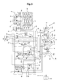
- FIG. 1 is a hydraulic circuit diagram of a hydraulic system according to an embodiment of the present invention.
- FIG. 2 is a hydraulic circuit diagram of a hydraulic system when the first leveling control valve is shifted according to an embodiment of the present invention
- FIG. 3 is a hydraulic circuit diagram of a hydraulic system when the second leveling control valve is shifted according to an embodiment of the present invention.
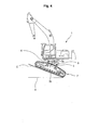
- FIG. 4 is a perspective view schematically illustrating an excavator moving on an inclined front area according to an embodiment of the present invention.
- FIG. 5 is a plan view schematically illustrating a mount state of actuators on a tilt plate as illustrated in FIG. 4
- FIG. 6 is a sectional view taken along line A-A in FIG. 5 .
- a hydraulic system for a leveling apparatus in excavator and forestry equipment including an engine 9, a hydraulic tank 13, a main hydraulic pump 10 and a pilot pump 12 respectively connected to the engine 9, a main control valve 20 installed between the main hydraulic pump 10 and the hydraulic tank 13 to control a start, a stop, and a direction change of a working device (not illustrated) in accordance with fluid pressure being supplied through a main flow path 14 during a spool shifting of the main control valve, and a tilt plate 3 tiltably installed between an upper frame 1 and a lower frame 2 and provided with a first tilt shaft 4 and a second tilt shaft 5 apart from each other at a specified angle, according to embodiments of the present invention, includes a pair of first and second actuators 6a and 6b, installed between the upper frame 1 and the lower frame 2, for rocking a lower part of the upper frame 1 in a direction of the first tilt shaft 4 during their extension and contraction, and another pair of third and fourth actuators 7a and 7b for rocking the lower part of the
- the main control valve 20 controls the operation of working devices, such as a bucket required in a typical excavator and forestry equipment, a feller header, a boom, and the like, and includes a plurality of directional valves connected in series to the center bypass flow path 18 for receiving a supply of fluid pressure from the main hydraulic pump 10 through the main flow path 14 to control a start, a stop, and a direction change of such working devices.
- the main control valve may further include a confluence valve for the confluence of fluid pressure of the second hydraulic pump 11.
- the hydraulic system for a leveling apparatus further includes a first hydraulic flow path 41 connected to a small chamber 31 of the first actuator 6a and a large chamber 33 of the second actuator 6b during the spool shifting of the first leveling control valve 23. Also, the hydraulic system for a leveling apparatus further includes a second hydraulic flow path 42 connected to a large chamber 34 of the third actuator 7a and a small chamber 35 of the fourth actuator 7b during the spool shifting of the second leveling control valve 24.
- the reference numeral "41a” denotes a return flow path through which the fluid pressure returns from the first actuator 6a and the second actuator 6b to the first leveling control valve 23 during the extension and contraction of the first and second actuators 6a and 6b
- "42a” denotes a return flow path through which the fluid pressure returns from the third actuator 7a and the fourth actuator 7b to the second leveling control valve 24 during the extension and contraction of the third and fourth actuators 7a and 7b.
- the hydraulic system for a leveling apparatus further includes double pilot check valves 50a, 50b, 50c, and 50d installed between the actuators 6a, 6b, 7a, and 7b and the first and second leveling control valves 23 and 24, respectively.
- the double pilot check valves 50a, 50b, 50c, and 50d are provided with cross flow paths 44, and are installed on the first hydraulic flow path 41 and the second hydraulic flow path 42.
- the flow control valve 26 is composed of an electro-proportional control valve, and the electro-proportional control valve is suitable to proportionally control the pilot signal pressure introduced from the reducing valve 25 in accordance with the control signal C from the leveling controller 40.
- the spool shift state (which corresponds to the change of a valve open area) of the first leveling control valve 23 and the second leveling control valve 24 is controlled in accordance with the control signal C from the leveling controller 24, which could be clearly understood by those skilled in the art.
- the fluid pressure introduced into the reducing valve 25 is discharged from the hydraulic pump 10, and is provided to the input ports 26a of the electro-proportional control valves 26 through the leveler flow path 21, an orifice 47, and a flow path 45.
- the hydraulic system for a leveling apparatus further includes second electro-proportional control valves 32 installed between the input ports 26a of the flow control valves 26 and the shuttle valves 29, respectively.
- the second electro-proportional control valves 32 provide input pilot pressure of the electro-proportional control valves to the shuttle valves 29.
- the leveling control signal C from the leveling controller 40 may be provided to the second electro-proportional control valves 32.
- the shuttle valves 29 are connected to output ports 27 of the flow control valves 26, and sense the fluid pressures of the input ports 26a and the output ports 27 of the flow control valves 26.
- the shuttle valves 29 include a plurality of shuttle valves 29a, 29b, and 29c connected in parallel to sense the fluid pressures of the input ports 26a and the output ports 27 of the flow control valves 26 for controlling the spool shifting of the first leveling control valve 23 and the second leveling control valve 24.
- relief valves 43 are further installed between the first and second leveling control valves 23 and 24 and a second return flow path 22.
- the tilt plate 3 installed between the upper frame 1 and the lower frame 2 is installed on left and right sides at a specified angle on the basis of a center line T in a length direction of the lower frame 2.
- the first actuator 6a and the second actuator 6b are installed along the first tilt shaft 4, and the third actuator 7a and the fourth actuator 7b are installed along the second tilt shaft 5.
- a pair of actuator holders 1b is provided on a lower part of the upper frame, on which typical swing bearings are mounted, to be coupled to the tilt plate 3.
- the first and second actuators 6a and 6b e.g. actuator pistons, are rotatably fixed into the actuator holders 1b.
- a tilt plate lower support plate 2a having a pair of actuator holders 2b is provided.
- the third and fourth actuators 7a and 7b e.g. actuator pistons, are rotatably fixed into the actuator holders 2b.
- the tilt plate 3 includes a pair of first pivot holders 3a formed to project upward to support the lower part of the upper frame 1, a pair of second pivot holders 3b formed to project downward and radially apart from the first pivot holders 3a by 90° to support the tilt plate lower support plate 2a, and a plurality of actuator holders 3c for rotatably fixing one side of the respective actuators 6a, 6b, 7a, and 7b.
- the lower part of the upper frame 1 and the tilt plate lower support plate 2a are rotatably fixed to the pair of first pivot holders 3a and the pair of second pivot holders 3b, respectively.
- the first tilt shaft 4 rotatably fixes the lower part of the upper frame 1 to the first pivot holders 3a of the tilt plate 3 in a shaft coupling method
- the second tilt shaft 5 crossing in an opposite direction to the first tilt shaft A rotatably fixes the tilt plate lower support plate 2a to the second pivot holders 3b.
- the actuator holders 3c of the tilt plate 3 rotatably fix cylinders of the first to fourth actuators 6a, 6b, 7a, and 7b.
- the cylinder sides of the actuators 6a, 6b, 7a, and 7b are fixed to the actuator holders 3c of the tilt plate 3, whereas their pistons are fixed to the lower part of the upper frame 1 and the actuator holders 1b and 2b of the tilt plate lower support plate 2a, so that the lower part of the upper frame 1 seesaws or rocks along the first tilt shaft 4 and the second tilt shaft 5 to control the tilt leveling against the horizontal surface during expansion and contraction of the actuators.
- the arrangement of the first tilt shaft 4 and the second tilt shaft 5 can be diversely modified.
- the excavator and forestry equipment typically travels or works on an inclined ground E against the horizontal surface H, and in this case, the horizontal level of the upper frame 1 is controlled depending on the degree of inclination against the horizontal surface H.
- the piston of the third actuator 7a fixed to the actuator holder 3c of the tilt plate 3 expands, and simultaneously the piston of the fourth actuator 7b in an opposite position contracts.
- the lower part of the upper frame 1 seesaws along the first tilt shaft 4 to keep the horizontal level against the ground E.
- the piston of the first actuator 6a expands and simultaneously the piston of the second actuator 6b in an opposite position contracts, so that the lower part of the upper frame 1 seesaws along the second tilt shaft 5 to keep the horizontal level against the ground E.
- the lower part of the upper frame 1 is level with the horizontal surface E.
- the hydraulic fluid discharged from the hydraulic pump 10 is supplied to the first leveling control valve 23 and the second leveling control valve 24 through the leveler flow path 21, and simultaneously the hydraulic fluid discharged from the reducing valve 25 through the branch flow path 45 is supplied to the input port 26a of the electro-proportional control valve 26 via a flow path 46 to form the fluid pressure at the input port 26a of the electro-proportional control valve 26.
- the electro-proportional control valve 26 is opened in accordance with the leveling control signal C from the leveling controller 40, and the pilot signal pressure applied from the reducing valve 25 shifts the valve spool of the first leveling control valve 23 downward.
- the hydraulic fluid is supplied to the small chamber 31 of the first actuator 6a through the main flow path 15, the leveler flow path 21, and the first hydraulic flow path 41, and simultaneously is supplied to the large chamber 33 of the second actuator 6b through the first hydraulic flow path 41.
- the upper frame 1 is kept at a horizontal level against the inclined lower frame 2.
- the hydraulic fluid supplied to the first and second actuators 6a and 6b for their expansion and contraction returns to the hydraulic tank 13 through the return flow path 41a and the second return flow path 22.
- the pilot pressures connected to the input port 26a and the output port 27 of the electro-proportional control valves 26 are applied to the shuttle valve 29 to shift the selector valve 30, and thus the shutoff valve 17 is shifted to close the center bypass flow path 18 by the pilot pressure introduced from the pilot pump 12.
- the main control valve 20 for controlling a working device such as a bucket for an excavator or the filler header for forestry equipment, is in a neutral state to shut off the returning fluid pressure, and thus the output of the hydraulic pump 10 can be efficiently used for the leveling control.
- the control signal C from the leveling controller is successively or continuously inputted to the electro-proportional control valves 26, based on a predetermined algorithm, to simultaneously shift the first leveling control valve 23 and the second leveling control valve 24, and thus the equipment and the upper frame 1 are kept at a horizontal level in the same manner as described above.
- the hydraulic system for a leveling apparatus in excavator and forestry equipment can stably control the horizontal level of an upper frame by connecting the leveling actuators installed on the tilt plate mounted between the upper frame and the lower frame to the leveler flow path branching from the main hydraulic pump and controlling the flow rate of hydraulic fluid being supplied to a working device side during the operation of the equipment.
Landscapes
- Engineering & Computer Science (AREA)
- Mining & Mineral Resources (AREA)
- Civil Engineering (AREA)
- General Engineering & Computer Science (AREA)
- Structural Engineering (AREA)
- Physics & Mathematics (AREA)
- Fluid Mechanics (AREA)
- Operation Control Of Excavators (AREA)
Claims (6)
- Nivellierungsvorrichtung für einen Bagger oder eine Forstmaschine, umfassend ein Hydrauliksystem, dadurch gekennzeichnet, dass das Hydrauliksystem eine Antriebsmaschine (9), einen Hydraulikbehälter (13), eine Haupthydraulikpumpe (10) und einer Pilotpumpe (12), die jeweils an der Antriebsmaschine (9) angeschlossen sind, umfasst, ferner ein Hauptregelventil (20), das zwischen der Haupthydraulikpumpe (10) und dem Hydraulikbehälter (13) angeordnet ist, um einen Start, ein Anhalten und eine Richtungsänderung einer Arbeitsvorrichtung dieses Baggers oder dieser Forstmaschine zu steuern, entsprechend einem durch einen Hauptfussweg (14) während einer Kolbenverschiebung des Hauptregelventils (20) beförderten Fluiddruck,
wobei die Nivellierungsvorrichtung eine Kippplatte (3) enthält, die zwischen einem oberen Rahmen (1) und einem unteren Rahmen (2) dieses Baggers oder der Forstmaschine kippend angeordnet und mit einer ersten Kippwelle (4) und mit einer Kippwelle (5) versehen ist, die mit einem bestimmten Winkel voneinander beanstandet sind,
wobei das Hydrauliksystem folgendes umfasst:ein Paar von ersten und zweiten Aktuatoren (6a, 6b), die zwischen dem oberen Rahmen (1) und dem unteren Rahmen (2) dieses Baggers oder der Forstmaschine angeordnet sind, um einen Unterteil des oberen Rahmens (1) in eine Richtung der ersten Kippwelle (4) bei deren Ausdehnung und Kontraktion schwingen zu lassen, und ein anderes Paar von dritten und vierten Aktuatoren (7a, 7b), um den Unterteil des oberen Rahmens (1) in eine Richtung der zweite Kippwelle (5) schwingen zu lassen;erste Nivellierungssteuerungsventile (23), die zwischen der Haupthydraulikpumpe (10) und den ersten und zweiten Aktuatoren (6a, 6b) angeordnet sind, zur gleichzeitigen Steuerung der Ausdehnung und der Kontraktion der ersten und zweiten Aktuatoren (6a,6b) gemäß dem Fluiddruck, der durch einen vom Hauptströmungsweg (14) abzweigenden Nivelliererströmungsweg (21) während der Kolbenverschiebung gefördert wird;zweite Nivellierungssteuerungsventile (24), die zwischen der Haupthydraulikpumpe (10) und den dritten und vierten Aktuatoren (7a, 7b) angeordnet sind, zur gleichzeitigen Steuerung der Ausdehnung und der Kontraktion der dritten und vierten Aktuatoren (7a, 7b) gemäß dem Fluiddruck durch einen vom Hauptströmungsweg (14) abzweigende Nivelliererströmungsweg (21) während der Kolbenverschiebung gefördert wird;ein Reduzierventil (25), das zwischen dem Nivellierungsströmungsweg (21) und dem Hydraulikbehälter (13) angeordnet ist, zur Aufnahme des Fluiddrucks vom Nivellierungsströmungsweg (21) und zur Ausgabe eines reduzierenden Pilotsignaldrucks;Strömungssteuerventile (26), die zwischen dem Reduzierventil (25) und den ersten und zweiten Nivellierungssteuerungsventilen (23, 24) geschaltet sind, zur Ausgabe des Pilotsignaldrucks für die Kolbenverschiebung des ersten Nivellierungssteuerungsventils (23) und des zweiten Nivellierungssteuerungsventils (24), wenn ein Steuersignal (C) von einer vorbestimmten Nivellierungssteuerung (40) angelegt wird;Wechselventile (29), die an den Pilotdruckanschlüssen (27) der Strömungssteuerventile (26) angeschlossen sind, zur Ausgabe des Pilotsignaldrucks an einen Wahlpilotströmungsweg (28) während der Kolbenverschiebung des ersten Nivellierungssteuerungsventils (23) oder des zweiten Nivellierungssteuerungsventils (24);ein Sperrventil (17), das am weitesten stromabwärts eines mittleren Bypass-Strömungswegs (18) angeordnet ist, der mit der Haupthydraulikpumpe (10) verbunden ist, zum Absperren des gemäß dem Pilotsignaldruck durch den mittleren Bypass-Strömungsweg (18) zum Hydraulikbehälter (13) rückzufliessenden Fluiddrucks; undein Wahlventil (30), das zwischen dem Sperrventil (17) und der Pilotpumpe (12) angeordnet ist, zur Öffnung eines Steuerströmungswegs (16), der von der Pilotpumpe (12) zum Sperrventil (17) geschaltet ist, gemäß dem von den Wechselventilen (29) zugeführten Pilotsignaldruck. - Nivellierungsvorrichtung gemäß Anspruch 1, wobei das Hydrauliksystem ferner einen ersten hydraulischen Strömungsweg (41) umfasst, der an einer kleinen Kammer (31) des ersten Aktuators (6a) und an einer großen Kammer (33) des zweiten Aktuators (6b) während der Kolbenverschiebung des ersten Nivellierungssteuerungsventils (23) angeschlossen ist.
- Nivellierungsvorrichtung gemäß Anspruch 2, wobei das Hydrauliksystem ferner einen zweiten hydraulischen Strömungsweg (42) umfasst, der an einer großen Kammer (34) des dritten Aktuators (7a) und an einer kleinen Kammer (35) des vierten Aktuators (7b) während der Kolbenverschiebung des zweiten Nivellierungssteuerungsventils (24) angeschlossen ist.
- Nivellierungsvorrichtung gemäß Anspruch 1, wobei das Hydrauliksystem ferner Doppelpilotabsperrventile (50a, 50b, 50c, 50d) umfasst, die zwischen den Aktuatoren (6a, 6b, 7a, 7b) und den jeweiligen ersten und zweiten Nivellierungs-steuerungsventilen (23, 24) positioniert sind.
- Hydrauliksystem nach Anspruch 1, wobei das Stömungssteuerventil (26) aus einem elektroproportionalen Steuerventil besteht.
- Nivellierungsvorrichtung gemäß Anspruch 5, wobei das Hydrauliksystem ferner zweite elektroproportionale Steuerventile (32) umfasst, die jeweils zwischen Einlassöffnungen (26a) der Strömungssteuerventile (26) und den Wechselventilen (29) angeordnet sind.
Applications Claiming Priority (1)
| Application Number | Priority Date | Filing Date | Title |
|---|---|---|---|
| KR20070132673 | 2007-12-17 |
Publications (3)
| Publication Number | Publication Date |
|---|---|
| EP2072690A2 EP2072690A2 (de) | 2009-06-24 |
| EP2072690A3 EP2072690A3 (de) | 2013-05-15 |
| EP2072690B1 true EP2072690B1 (de) | 2014-06-04 |
Family
ID=40419490
Family Applications (1)
| Application Number | Title | Priority Date | Filing Date |
|---|---|---|---|
| EP08021484.4A Not-in-force EP2072690B1 (de) | 2007-12-17 | 2008-12-11 | Hydraulisches System zur Nivellierung einer Vorrichtung in einer Bagger- und Forstwirtschaftsausrüstung |
Country Status (5)
| Country | Link |
|---|---|
| US (1) | US7753382B2 (de) |
| EP (1) | EP2072690B1 (de) |
| JP (1) | JP5259366B2 (de) |
| KR (1) | KR101032728B1 (de) |
| CA (1) | CA2646085C (de) |
Families Citing this family (7)
| Publication number | Priority date | Publication date | Assignee | Title |
|---|---|---|---|---|
| US8579069B2 (en) | 2010-12-23 | 2013-11-12 | Caterpillar Inc. | Forestry machines with transverse engine and hydraulic system installation |
| US9591811B2 (en) | 2011-06-24 | 2017-03-14 | Jarraff Industries, Inc. | Mobile tree-trimming apparatus |
| EP3808168B1 (de) | 2013-09-30 | 2024-07-31 | Jarraff Industries, LLC | Drehantrieb mit durchgehendem flüssigkeitskreislauf |
| FI126994B (fi) * | 2016-08-31 | 2017-09-15 | Ponsse Oyj | Sovitelma ja menetelmä kiertoliikkeen mahdollistamiseksi ajoneuvossa tai liikkuvassa työkoneessa |
| WO2022147016A1 (en) | 2020-12-29 | 2022-07-07 | Oshkosh Corporation | Turntable leveling system for a mobile elevating work platform |
| CN116534746B (zh) * | 2023-05-31 | 2026-01-30 | 徐州建机工程机械有限公司 | 行走式塔机底架的液压调平系统 |
| US12507639B2 (en) | 2023-08-08 | 2025-12-30 | Deere & Company | Intelligent boom control with end effector leveling for a feller buncher |
Family Cites Families (19)
| Publication number | Priority date | Publication date | Assignee | Title |
|---|---|---|---|---|
| DE693282C (de) * | 1933-05-12 | 1940-07-05 | Luebecker Maschb Ges | Eimerkettenbagger mit einem die Eimerleiter tragenden, in waagerechter Ebene schwenkbaren und in senkrecht zueinander stehenden lotrechten Ebenen einstellbaren Baggeroberbau |
| DE2539754B2 (de) * | 1975-09-06 | 1978-10-26 | Fried. Krupp Gmbh, 4300 Essen | Gerät mit Vierpunkt-Abstützung eines schweren Körpers auf einem anderen Körper |
| JPS55138523A (en) * | 1979-04-13 | 1980-10-29 | Komatsu Ltd | Posture control system for slewing excavator |
| US4565486A (en) * | 1982-09-29 | 1986-01-21 | Timbco Hydraulics Inc. | Device for handling material |
| US4650017A (en) * | 1985-02-18 | 1987-03-17 | Industries Tanguay, Inc. | Crawler-mounted machine for travel over natural terrain |
| JPH0765601B2 (ja) * | 1985-08-27 | 1995-07-19 | 株式会社小松製作所 | 建設機械 |
| US4679803A (en) * | 1986-01-27 | 1987-07-14 | The United States Of America As Represented By The Secretary Of Agriculture | Apparatus for maintaining stability of mobile land vehicles on sloping terrain |
| US4899841A (en) * | 1989-01-12 | 1990-02-13 | Deere & Company | Leveling assembly for a work vehicle |
| JP3062364B2 (ja) * | 1992-11-27 | 2000-07-10 | ヤンマー農機株式会社 | キャビン揺動式作業車 |
| JP3168083B2 (ja) * | 1992-12-03 | 2001-05-21 | 岡本 俊仁 | 法面等の加工機械 |
| US5337847A (en) * | 1993-01-15 | 1994-08-16 | Risley Fluidic Power Ltd. | Four-way levelling mechanism for off-road vehicle |
| US6105699A (en) | 1998-06-15 | 2000-08-22 | Cameco Industries, Inc. | Heavy equipment apparatus that includes undercarriage with mobile tilting upper |
| US6173973B1 (en) | 1998-07-09 | 2001-01-16 | Timberjack Inc. | Forestry machine swing-house leveling mechanism |
| DE69909425T2 (de) * | 1998-08-04 | 2004-04-15 | Ingersoll-Rand Co. | System zum nivellieren und abstützen von dem rahmen eines gabelhubwagens |
| US6241263B1 (en) * | 2000-04-25 | 2001-06-05 | Caterpillar Inc. | Tilt mechanism for adjusting position of an upper body assembly relative to an undercarriage assembly of a feller buncher |
| JP2002242226A (ja) * | 2001-02-13 | 2002-08-28 | Komatsu Ltd | 上部旋回体傾動式作業車両 |
| US6609581B2 (en) | 2001-09-13 | 2003-08-26 | Tigercat Industries Inc. | Stable leveler |
| JP2007170485A (ja) * | 2005-12-20 | 2007-07-05 | Shin Caterpillar Mitsubishi Ltd | エネルギ回収・再生装置 |
| KR100956995B1 (ko) * | 2007-11-07 | 2010-05-11 | 볼보 컨스트럭션 이키프먼트 홀딩 스웨덴 에이비 | 산림장비 및 굴삭기용 레벨링 장치 |
-
2008
- 2008-11-26 KR KR1020080118154A patent/KR101032728B1/ko not_active Expired - Fee Related
- 2008-12-08 US US12/329,646 patent/US7753382B2/en not_active Expired - Fee Related
- 2008-12-09 CA CA2646085A patent/CA2646085C/en not_active Expired - Fee Related
- 2008-12-11 EP EP08021484.4A patent/EP2072690B1/de not_active Not-in-force
- 2008-12-12 JP JP2008316690A patent/JP5259366B2/ja not_active Expired - Fee Related
Also Published As
| Publication number | Publication date |
|---|---|
| KR101032728B1 (ko) | 2011-05-06 |
| KR20090065437A (ko) | 2009-06-22 |
| CA2646085C (en) | 2016-06-21 |
| EP2072690A3 (de) | 2013-05-15 |
| CA2646085A1 (en) | 2009-06-17 |
| US20090152025A1 (en) | 2009-06-18 |
| EP2072690A2 (de) | 2009-06-24 |
| JP2009144504A (ja) | 2009-07-02 |
| US7753382B2 (en) | 2010-07-13 |
| JP5259366B2 (ja) | 2013-08-07 |
Similar Documents
| Publication | Publication Date | Title |
|---|---|---|
| CA2646085C (en) | Hydraulic system for leveling apparatus in excavator and forestry equipment | |
| US7500360B2 (en) | Hydraulic driving system of construction machinery | |
| EP0874090B1 (de) | Hydraulische antriebsvorrichtung | |
| JP6134614B2 (ja) | 作業機械の駆動装置 | |
| US10526767B2 (en) | Construction machine | |
| KR101425245B1 (ko) | 유압 셔블의 유압 구동 장치 | |
| US10829908B2 (en) | Construction machine | |
| KR20160045128A (ko) | 건설기계의 유압 구동 장치 | |
| US11499296B2 (en) | Construction machine | |
| JP2583148B2 (ja) | 油圧式掘削機の油圧制御回路 | |
| US10889964B2 (en) | Drive system for construction machine | |
| US10072396B2 (en) | Working machine control system | |
| KR102794315B1 (ko) | 작업 기계 | |
| JP4558465B2 (ja) | 建設機械の油圧制御装置 | |
| JP3597693B2 (ja) | 油圧駆動回路 | |
| JP6718371B2 (ja) | 油圧作動装置 | |
| US11198989B2 (en) | Hydraulic system for working machine | |
| US10208457B2 (en) | Working machine control system | |
| KR20070095446A (ko) | 유압 구동 장치 | |
| JP4423149B2 (ja) | 建設機械 | |
| JPH11247235A (ja) | ブームを備えた作業機械の油圧回路 | |
| JPH10299027A (ja) | 建設機械の油圧駆動装置 | |
| JP2024013027A (ja) | 建設機械の制御方法、建設機械用制御プログラム、建設機械用制御システム、建設機械 | |
| JPS5985044A (ja) | パワ−シヨベル等の建設機械 | |
| JP2006242337A (ja) | 建設機械の油圧制御装置 |
Legal Events
| Date | Code | Title | Description |
|---|---|---|---|
| PUAI | Public reference made under article 153(3) epc to a published international application that has entered the european phase |
Free format text: ORIGINAL CODE: 0009012 |
|
| AK | Designated contracting states |
Kind code of ref document: A2 Designated state(s): AT BE BG CH CY CZ DE DK EE ES FI FR GB GR HR HU IE IS IT LI LT LU LV MC MT NL NO PL PT RO SE SI SK TR |
|
| AX | Request for extension of the european patent |
Extension state: AL BA MK RS |
|
| PUAL | Search report despatched |
Free format text: ORIGINAL CODE: 0009013 |
|
| AK | Designated contracting states |
Kind code of ref document: A3 Designated state(s): AT BE BG CH CY CZ DE DK EE ES FI FR GB GR HR HU IE IS IT LI LT LU LV MC MT NL NO PL PT RO SE SI SK TR |
|
| AX | Request for extension of the european patent |
Extension state: AL BA MK RS |
|
| RIC1 | Information provided on ipc code assigned before grant |
Ipc: E02F 9/02 20060101AFI20130410BHEP Ipc: A01G 23/081 20060101ALI20130410BHEP Ipc: F15B 11/20 20060101ALI20130410BHEP Ipc: E02F 9/22 20060101ALI20130410BHEP |
|
| 17P | Request for examination filed |
Effective date: 20131114 |
|
| RBV | Designated contracting states (corrected) |
Designated state(s): AT BE BG CH CY CZ DE DK EE ES FI FR GB GR HR HU IE IS IT LI LT LU LV MC MT NL NO PL PT RO SE SI SK TR |
|
| GRAP | Despatch of communication of intention to grant a patent |
Free format text: ORIGINAL CODE: EPIDOSNIGR1 |
|
| AKX | Designation fees paid |
Designated state(s): DE FR GB IT |
|
| INTG | Intention to grant announced |
Effective date: 20140102 |
|
| GRAS | Grant fee paid |
Free format text: ORIGINAL CODE: EPIDOSNIGR3 |
|
| GRAA | (expected) grant |
Free format text: ORIGINAL CODE: 0009210 |
|
| AK | Designated contracting states |
Kind code of ref document: B1 Designated state(s): DE FR GB IT |
|
| REG | Reference to a national code |
Ref country code: GB Ref legal event code: FG4D |
|
| REG | Reference to a national code |
Ref country code: DE Ref legal event code: R096 Ref document number: 602008032525 Country of ref document: DE Effective date: 20140717 |
|
| PGFP | Annual fee paid to national office [announced via postgrant information from national office to epo] |
Ref country code: DE Payment date: 20140924 Year of fee payment: 7 Ref country code: FR Payment date: 20140925 Year of fee payment: 7 Ref country code: GB Payment date: 20141014 Year of fee payment: 7 |
|
| REG | Reference to a national code |
Ref country code: DE Ref legal event code: R097 Ref document number: 602008032525 Country of ref document: DE |
|
| PGFP | Annual fee paid to national office [announced via postgrant information from national office to epo] |
Ref country code: IT Payment date: 20141008 Year of fee payment: 7 |
|
| PLBE | No opposition filed within time limit |
Free format text: ORIGINAL CODE: 0009261 |
|
| STAA | Information on the status of an ep patent application or granted ep patent |
Free format text: STATUS: NO OPPOSITION FILED WITHIN TIME LIMIT |
|
| 26N | No opposition filed |
Effective date: 20150305 |
|
| REG | Reference to a national code |
Ref country code: DE Ref legal event code: R097 Ref document number: 602008032525 Country of ref document: DE Effective date: 20150305 |
|
| REG | Reference to a national code |
Ref country code: DE Ref legal event code: R119 Ref document number: 602008032525 Country of ref document: DE |
|
| GBPC | Gb: european patent ceased through non-payment of renewal fee |
Effective date: 20151211 |
|
| REG | Reference to a national code |
Ref country code: FR Ref legal event code: ST Effective date: 20160831 |
|
| PG25 | Lapsed in a contracting state [announced via postgrant information from national office to epo] |
Ref country code: GB Free format text: LAPSE BECAUSE OF NON-PAYMENT OF DUE FEES Effective date: 20151211 Ref country code: DE Free format text: LAPSE BECAUSE OF NON-PAYMENT OF DUE FEES Effective date: 20160701 |
|
| PG25 | Lapsed in a contracting state [announced via postgrant information from national office to epo] |
Ref country code: FR Free format text: LAPSE BECAUSE OF NON-PAYMENT OF DUE FEES Effective date: 20151231 |
|
| PG25 | Lapsed in a contracting state [announced via postgrant information from national office to epo] |
Ref country code: IT Free format text: LAPSE BECAUSE OF NON-PAYMENT OF DUE FEES Effective date: 20151211 |