EP2071994B1 - Halteeinrichtung - Google Patents
Halteeinrichtung Download PDFInfo
- Publication number
- EP2071994B1 EP2071994B1 EP08090006.1A EP08090006A EP2071994B1 EP 2071994 B1 EP2071994 B1 EP 2071994B1 EP 08090006 A EP08090006 A EP 08090006A EP 2071994 B1 EP2071994 B1 EP 2071994B1
- Authority
- EP
- European Patent Office
- Prior art keywords
- radiator
- rod
- holding device
- die
- connection
- Prior art date
- Legal status (The legal status is an assumption and is not a legal conclusion. Google has not performed a legal analysis and makes no representation as to the accuracy of the status listed.)
- Active
Links
- 238000010438 heat treatment Methods 0.000 claims description 12
- 230000002452 interceptive effect Effects 0.000 claims 1
- 241001295925 Gegenes Species 0.000 description 1
- 238000011161 development Methods 0.000 description 1
- 230000018109 developmental process Effects 0.000 description 1
- 238000009434 installation Methods 0.000 description 1
- 230000007246 mechanism Effects 0.000 description 1
Images


Classifications
-
- A—HUMAN NECESSITIES
- A47—FURNITURE; DOMESTIC ARTICLES OR APPLIANCES; COFFEE MILLS; SPICE MILLS; SUCTION CLEANERS IN GENERAL
- A47K—SANITARY EQUIPMENT NOT OTHERWISE PROVIDED FOR; TOILET ACCESSORIES
- A47K10/00—Body-drying implements; Toilet paper; Holders therefor
- A47K10/04—Towel racks; Towel rails; Towel rods; Towel rolls, e.g. rotatable
- A47K10/06—Towel racks; Towel rails; Towel rods; Towel rolls, e.g. rotatable combined with means for drying towels
-
- F—MECHANICAL ENGINEERING; LIGHTING; HEATING; WEAPONS; BLASTING
- F24—HEATING; RANGES; VENTILATING
- F24D—DOMESTIC- OR SPACE-HEATING SYSTEMS, e.g. CENTRAL HEATING SYSTEMS; DOMESTIC HOT-WATER SUPPLY SYSTEMS; ELEMENTS OR COMPONENTS THEREFOR
- F24D2220/00—Components of central heating installations excluding heat sources
- F24D2220/20—Heat consumers
- F24D2220/2009—Radiators
- F24D2220/2018—Column radiators having vertically extending tubes
Definitions
- the invention relates to a holding device with a rod-shaped handle or retaining element for attachment to a radiator, in particular a flat radiator, a heating wall or on a tubular heater according to the preamble of claim 1.
- the invention is for fixing rods for towel bars and the like. suitable for radiators in the bathroom and sanitary area.
- Such fastening devices are used in the sanitary area eg for bath towel bars, handles or the like.
- holder and carrier are bolted together or are connected by means of interlocking parts after assembly. These parts may be formed eg dovetailed.
- fastening screws can be secured by clamping screws or snap closures to prevent release of the holder from the carrier under load in any direction.
- a towel radiator with a substantially rectangular radiator plate is known.
- the radiator plate of this radiator is provided with Kantenabdeckprofilen, wherein the lateral along the height extending Kantenabdeckprofile each having a holder which holds one end of a rod, wherein the holder and the lateral Kantenabdeckprofil are preferably integrally formed.
- the Kantenabdeckprofil can also be provided with locking means.
- a towel rail in which a horizontal rod is provided on both sides with holding devices which are designed as attachable on the upper edge of plate radiators retaining clips and in which the support rod at a distance from the outer clamping leg of the retaining clips extending by means of support arm with the outside of the outer clamping legs connected is.
- Such retaining clips are attached to the upper edge of panel radiators and are therefore not suitable for wall mounting of heating walls or tubular heaters.
- a fastening device for a rod is known with a wall-mountable carrier and a wall bracket which can be connected to the carrier. The wall holder is connected via a complex clamping device with the carrier.
- a radiator with a towel holder is disclosed.
- the towel holder is firmly screwed to the side panel of the radiator, wherein the bracket for receiving the towels in its longitudinal axis is rotatable.
- the object of the present invention is to provide a holding device with a rod-shaped handle or holding element for attachment to a radiator of the type mentioned, which improves the known from the prior art holding devices, in particular with respect to the load behavior of the holding device and thus the radiator itself.
- the invention includes a holding device with a rod-shaped or tubular grip or retaining element for attachment to a radiator, a rod holder and means for attaching the rod holder to the radiator, wherein the rod holder comprises an eccentric with adjusting means, which via a receptacle in the fastener with the Fastening means can be brought into a cooperating connection and the holding device is continuously adjustable vertically by this connection along the height of the radiator.
- a stepless vertical adjustability of the retaining element is thus allowed in response to a vertical load.
- the contact pressure and thus the strength of the connection to the heating element are automatically increased by the adjustment of the eccentric vice associated with the load.
- the holding device or parts thereof are not damaged. After a "slip" this can be returned to the starting position. Covers or panels of the radiator are not destroyed or damaged in an overload by the inventive design of the holding device.
- the consumer can determine the height of the holding device itself and also change individually. On the radiator itself no changes are required for the attachment of the fasteners for the holding device.
- the rod holder comprises a mounting sleeve which receives the eccentric and one end of the rod-shaped or tubular grip or holding element.
- the eccentric tensioner has a tab which engages in an opening of the mounting sleeve when connected, wherein the connection is released by pressing the tab again.
- the mounting sleeve is connected by a latching and / or screw connection with one end of the rod-shaped or tubular grip or holding element.
- the fastening means on a lateral right-angled fold, which can be introduced under a side cover of the radiator, whereby the holding device can be fixed to a flat radiator or a heating wall.
- the fastener is formed in a tubular heater such that its shape allows at least a partial clasping of the heating tubes of the tubular heater.
Landscapes
- Health & Medical Sciences (AREA)
- Public Health (AREA)
- Clamps And Clips (AREA)
Description
- Die Erfindung betriff eine Halteeinrichtung mit einem stangenförmigen Griff- oder Halteelement zur Befestigung an einem Heizkörper, insbesondere einem Flachheizkörper, einer Heizwand oder an einem Rohrheizkörper nach dem Oberbegriff des Anspruchs 1.
- Insbesondere ist die Erfindung zur Befestigung von Stangen für Handtuchhalter u.ä. an Heizkörpern im Bad- und Sanitärbereich geeignet.
Derartige Befestigungsvorrichtungen werden im Sanitärbereich z.B. für Badetuchstangen, Haltegriffe oder dgl. eingesetzt. Dabei sind Halter und Träger miteinander verschraubt oder werden nach der Montage mittels ineinander greifender Teile verbunden. Diese Teile können z.B. schwalbenschwanzförmig ausgebildet sein. Zusätzlich können solche Befestigungsschrauben durch Klemmschrauben oder Schnappverschlüsse gesichert sein, um ein Lösen des Halters vom Träger bei einer Belastung in beliebiger Richtung auszuschließen. - Aus der
DE 89 02 985 U1 ist ein Badheizkörper mit einer im Wesentlichen rechteckigen Heizkörperplatte bekannt. Entlang der Außenkanten der Heizkörperplatte ist dieser Heizkörper mit Kantenabdeckprofilen versehen, wobei die seitlichen sich entlang der Bauhöhe erstreckenden Kantenabdeckprofile jeweils eine Halterung aufweisen, die jeweils ein Ende einer Stange haltert, wobei die Halterung und das seitliche Kantenabdeckprofil vorzugsweise einstückig ausgebildet sind. Das Kantenabdeckprofil kann aber auch mit Rastmitteln versehen sein. - In der
DE-OS 197 03 827 A1
Aus derDE 295 05 002 U1 ist eine Befestigungsvorrichtung für eine Stange mit einem an der einer Wand befestigbaren Träger und einem mit dem Träger verbindbaren Wandhalter bekannt. Der Wandhalter ist dabei über eine aufwendige Spanneinrichtung mit dem Träger verbunden. - In der Druckschrift
FR 2187979 A1 - Aus der
DE 299 23 144 U1 ist ein mittels einem Gelenk beweglicher Handtuchhalter für einen Heizkörper bekannt. Die Tragarme für die Haltestange sind dabei aber am Heizkörper in der oberen Abdeckung fixiert und nicht verstellbar. - Bei derartigen Handtuchhaltevorrichtungen führen zu große Belastungen zu einem "Rutschen" der Befestigungselemente und somit zu einer Mehrbelastung der Heizkörperbefestigung. Dabei können die Befestigungselemente und Halteelemente durch Überbelastung beschädigt oder gar zerstört werden. Weiter können auch Abdeckungen des Heizkörpers dabei zerstört oder beschädigt werden.
- Die Aufgabe der vorliegenden Erfindung besteht darin, eine Halteeinrichtung mit einem stangenförmigen Griff- oder Halteelement zur Befestigung an einem Heizkörper der eingangs genannten Art zu schaffen, die die aus dem Stand der Technik bekannten Halteeinrichtungen verbessert, insbesondere in Bezug auf das Belastungsverhalten der Halteeinrichtung und damit des Heizkörpers selber.
- Erfindungsgemäß wird diese Aufgabe durch die Merkmale des Anspruchs 1 gelöst. Vorteilhafte Weiterbildungen der Erfindung sind in zugehörigen Ansprüchen 2 bis 5 beschrieben.
Demnach beinhaltet die Erfindung eine Halteeinrichtung mit einem stangen- oder rohrförmigen Griff- oder Halteelement zur Befestigung an einem Heizkörper, einer Stangenhalterung und Mitteln zur Befestigung der Stangenhalterung am Heizkörper, wobei die Stangenhalterung einen Exzenterspanner mit Stellmitteln umfasst, die über eine Aufnahme im Befestigungsmittel mit dem Befestigungsmittel in eine zusammenwirkende Verbindung bringbar sind und die Halteeinrichtung durch diese Verbindung stufenlos vertikal entlang der Höhe des Heizkörpers verstellbar ist. Dadurch wird demnach in Abhängigkeit einer vertikalen Belastung eine stufenlose vertikale Verstellbarkeit des Halteelementes erlaubt. - Bei einer vertikalen Belastung des Halteelementes erhöht sich durch die mit der Belastung einhergehende Verstellung des Exzenterspanners automatisch der Anpressdruck und somit die Festigkeit der Verbindung mit dem Heizkörper. Dabei werden die Halteeinrichtung oder Teile davon nicht beschädigt. Nach einem "Verrutschen" kann diese wieder in die Ausgangsposition zurückgebracht werden. Abdeckungen oder Verkleidungen des Heizkörpers werden bei einer Überlastung durch die erfindungsgemäße Ausbildung der Halteeinrichtung nicht zerstört oder beschädigt. Weiter kann der Verbraucher die Höhe der Halteeinrichtung selbst bestimmen und auch individuell ändern. Am Heizkörper selber sind für die Anbringung der Befestigungen für die Halteeinrichtung keine Veränderungen erforderlich.
Vorteilhaft umfasst die Stangenhalterung dabei eine Montagehülse, die den Exzenterspanner und jeweils ein Ende des stangen- oder rohrförmigen Griff- oder Halteelementes aufnimmt. Der Exzenterspanner weist eine Lasche auf, die in eine Öffnung der Montagehülse bei Verbindung einrastet, wobei die Verbindung durch Drücken der Lasche wieder lösbar ist. - Die Montagehülse ist dabei durch eine Rast- und /oder Schraubverbindung mit jeweils einem Ende des stangen- oder rohrförmigen Griff- oder Halteelementes verbunden. Nach einer besonderen Ausführung der Erfindung weisen die Befestigungsmittel eine seitliche rechtwinklige Abkantung auf, die unter eine seitliche Abdeckung des Heizkörpers einbringbar ist, wodurch die Halteeinrichtung an einem Flachheizkörper oder einer Heizwand befestigt werden kann.
Vorteilhaft ist das Befestigungsmittel bei einem Rohrheizkörper derart ausgebildet, dass dessen Form zumindest eine teilweise Umklammerung der Heizrohre des Rohrheizkörpers erlaubt. - Die Erfindung soll nachfolgend anhand von in Zeichnungen dargestellten Ausführungsbeispielen näher erläutert werden.
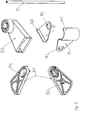
In den Zeichnungen zeigen: - Fig. 1
- die Einzelteile einer Haltevorrichtung in Explosionsdarstellung mit einem vertikalen Flachheizkörper,
- Fig. 2
- die Einzelteile der Haltevorrichtung,
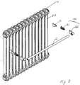
- Fig. 3
- die Einzelteile einer Haltevorrichtung in Explosiondarstellung mit einem vertikalen Rohrheizkörper,
- Fig. 4
- die Befestigung eines Befestigungsmittels 14 an einem vertikalen Heizrohr im Detail.
Die Stangenhalterung 12 umfasst weiter eine Montagehülse 12.3, die den Exzenterspanner 12.1 und jeweils ein Ende des stangen- oder rohrförmigen Griff- oder Halteelementes 11 aufnimmt. Der Exzenterspanner 12.1 weist eine Lasche 12.4 auf, die
in eine Öffnung der Montagehülse 12.3 bei Verbindung einrastet, wobei die Verbindung durch Drücken der Lasche 12.4 wieder lösbar ist.
Die Montagehülse 12.3 wird dabei durch eine Rast- und /oder Schraubverbindung mit jeweils einem Ende des stangen- oder rohrförmigen Griff- oder Halteelementes 11 verbunden. Die Befestigungsmittel 13 weisen bei einem Flachheizkörper vorzugsweise eine seitliche rechtwinklige Abkantung 13.2 auf, die unter eine seitliche Abdeckung des Flachheizkörpers 2 eingesteckt werden.
Die Montage bei einem Flachheizkörper 2 erfolgt wie nachfolgend beschrieben.
Das stangen- oder rohrförmigen Griff- oder Halteelementes 11 wird zunächst an beiden Enden mit der Montagehülse 12.3 durch eine Rast- und /oder Schraubverbindung verbunden. Die Exzenterspanner 12.1 mit den Stellmitteln 12.2 werden jeweils über die Aufnahme 13.1 in den rechts und linksseitigen Befestigungsmitteln 13 mit dem Befestigungsmittel 13 in eine zusammenwirkende Verbindung gebracht. Die Befestigungsmittel 13 werden mit den seitlichen rechtwinkligen Abkantungen 13.2 hinter die Umkantung der seitlichen Abdeckung 2.1 des Heizkörpers 2 eingesteckt und mit dem Exzenterspanner 12.1 justiert. Danach werden das linke und das rechte Befestigungsmittel 13 auf eine jeweilige Höhe waagerecht eingestellt. Die Einstellung ist dabei stufenlos möglich. Anschließend werden die beiden Montagehülsen 12.3 einschließlich dem Halteelement 11 über die jeweiligen Exzenterspanner 12.1 und Befestigungsmittel 13 geschoben und verrastet. Durch die Montagehülsen 12.3 wird ein Lösen oder Verdrehen des Exzenterspanners 12.1 verhindert. Das Halteelement 11 kann aber auch direkt mit dem Exzenterspanner 12.1 verbunden werden. Die Montagehülse 12.3 ist dann nicht erforderlich. Verriegelungsmechanismen (Schnappelemente, Verriegelungsbolzen) gegen ein unbeabsichtigtes Lösen der Verbindung sind dann aber angebracht.
Die
Claims (5)
- Halteeinrichtung zur Befestigung an einem Heizkörper (2, 2'), umfassend ein stangen- oder rohrförmiges Griff- oder Halteelement (11), eine Stangenhalterung (12) und Mitteln zur Befestigung der Stangenhalterung (12) am Heizkörper (2, 2'), dadurch gekennzeichnet, dass die Stangenhalterung (12) einen Exzenterspanner (12.1) mit Stellmitteln (12.2) umfasst, die über eine Aufnahme (13.1) im Befestigungsmittel (13, 14) mit dem Befestigungsmittel (13, 14) in eine zusammenwirkende Verbindung bringbar sind, wobei die Halteeinrichtung durch diese Verbindung stufenlos vertikal entlang der Höhe des Heizkörpers (2, 2') verstellbar ist.
- Halteeinrichtung nach Anspruch 1, dadurch gekennzeichnet, dass die Stangenhalterung (12) eine Montagehülse (12.3) umfasst, die den Exzenterspanner (12.1) und jeweils ein Ende des stangen- oder rohrförmigen Griff- oder Halteelementes (11) aufnimmt, wobei der Exzenterspanner (12.1) eine Lasche (12.4) aufweist, die in eine Öffnung der Montagehülse (12.3) bei Verbindung einrastbar ist und die Verbindung durch Drücken der Lasche (12.4) wieder lösbar ist.
- Halteeinrichtung nach Anspruch 2, dadurch gekennzeichnet, dass die Montagehülse (12.3) durch eine Rast- und /oder Schraubverbindung mit jeweils einem Ende des stangen- oder rohrförmigen Griff- oder Halteelementes (11) verbindbar ist.
- Halteeinrichtung nach den Ansprüchen 1 bis 3, dadurch gekennzeichnet, dass die Befestigungsmittel (13) eine seitliche rechtwinklige Abkantung (13.2) aufweisen, die in eine seitliche Abdeckung des Heizkörpers (2) einbringbar sind.
- Halteeinrichtung nach einem der Ansprüche 1 bis 3, dadurch gekennzeichnet, dass die Befestigungsmittel (14) eine Form zur zumindest teilweisen Umklammerung der Heizrohre (2.3) eines Rohrheizkörpers (2') aufweisen.
Priority Applications (1)
| Application Number | Priority Date | Filing Date | Title |
|---|---|---|---|
| PL08090006T PL2071994T3 (pl) | 2007-12-21 | 2008-12-10 | Uchwyt |
Applications Claiming Priority (1)
| Application Number | Priority Date | Filing Date | Title |
|---|---|---|---|
| DE200720018115 DE202007018115U1 (de) | 2007-12-21 | 2007-12-21 | Halteeinrichtung |
Publications (3)
| Publication Number | Publication Date |
|---|---|
| EP2071994A2 EP2071994A2 (de) | 2009-06-24 |
| EP2071994A3 EP2071994A3 (de) | 2013-05-01 |
| EP2071994B1 true EP2071994B1 (de) | 2018-03-28 |
Family
ID=39265405
Family Applications (1)
| Application Number | Title | Priority Date | Filing Date |
|---|---|---|---|
| EP08090006.1A Active EP2071994B1 (de) | 2007-12-21 | 2008-12-10 | Halteeinrichtung |
Country Status (3)
| Country | Link |
|---|---|
| EP (1) | EP2071994B1 (de) |
| DE (1) | DE202007018115U1 (de) |
| PL (1) | PL2071994T3 (de) |
Families Citing this family (3)
| Publication number | Priority date | Publication date | Assignee | Title |
|---|---|---|---|---|
| DE102009041565A1 (de) * | 2009-09-15 | 2011-03-24 | Schröder, Franz Anton | Haltevorrichtung |
| DE102010027451A1 (de) * | 2010-07-17 | 2012-01-19 | Curtania Gmbh | Wand- oder Deckenhalter für ein schienenartiges Aufhängesystem |
| DE202011105966U1 (de) * | 2011-09-21 | 2013-01-09 | M.A.C.'s Holding Gmbh | Haltevorrichtung |
Family Cites Families (7)
| Publication number | Priority date | Publication date | Assignee | Title |
|---|---|---|---|---|
| US2087757A (en) * | 1936-09-15 | 1937-07-20 | Donald J Foss | Drying rack |
| FR2187979A1 (de) * | 1972-06-13 | 1974-01-18 | Bour Armand Le | |
| DE8902985U1 (de) | 1989-03-10 | 1989-05-11 | Kermi Gmbh, 8350 Plattling, De | |
| DE29505002U1 (de) | 1995-03-24 | 1995-05-18 | Jado Design Armatur Und Beschl | Befestigungsvorrichtung für eine Stange |
| DE29603525U1 (de) | 1996-02-27 | 1996-07-25 | Mueller Sen Werner | Handtuchhalter |
| DE29923144U1 (de) * | 1999-02-10 | 2000-04-27 | Puehringer Siegfried | Beweglicher Handtuchhalter |
| DE29909663U1 (de) * | 1999-06-02 | 1999-08-26 | Kermi Gmbh | Verbindungselement mit einer Rastverbindung |
-
2007
- 2007-12-21 DE DE200720018115 patent/DE202007018115U1/de not_active Expired - Lifetime
-
2008
- 2008-12-10 PL PL08090006T patent/PL2071994T3/pl unknown
- 2008-12-10 EP EP08090006.1A patent/EP2071994B1/de active Active
Non-Patent Citations (1)
| Title |
|---|
| None * |
Also Published As
| Publication number | Publication date |
|---|---|
| EP2071994A3 (de) | 2013-05-01 |
| EP2071994A2 (de) | 2009-06-24 |
| DE202007018115U1 (de) | 2008-04-03 |
| PL2071994T3 (pl) | 2018-08-31 |
Similar Documents
| Publication | Publication Date | Title |
|---|---|---|
| EP2071994B1 (de) | Halteeinrichtung | |
| EP2224177B1 (de) | Hals- und Justiervorrichtung für Heizkörper | |
| DE102013003822B3 (de) | Armaturablage | |
| AT503382B1 (de) | Untergestell für eine sanitärwanne | |
| EP1706548B1 (de) | Wandhalterung für eine handbrause | |
| EP2628426B1 (de) | Verdrehsicherer Handtuchhalter | |
| DE202007000508U1 (de) | Einrichtung zum Befestigen einer Abdeckhaube an einem Becken sowie mit einer solchen Befestigungseinrichtung ausgestatteter Waschtisch | |
| DE202007017319U1 (de) | Halte- und Justiervorrichtung für Rohr- und/oder Badheizkörper | |
| DE102017201619A1 (de) | Haltevorrichtung für eine Sanitärbaugruppe | |
| WO1994021970A1 (de) | Standkonsole für heizkörper | |
| EP3628201A1 (de) | Relingsystem für eine duschabtrennung | |
| EP1232714B1 (de) | Halter für Heimtextilien | |
| DE19828877A1 (de) | Stütz- und Ablagevorrichtung | |
| EP1935304A1 (de) | Befestigungselement für einen Heizkörper | |
| EP1693624B1 (de) | Heizkörper | |
| DE102010019326B4 (de) | Antennenhalter | |
| EP1275906B1 (de) | Vorrichtung zur Sicherung eines Heizkörpers | |
| DE202004002690U1 (de) | Einhängesitz | |
| DE3608731C2 (de) | Abstandshaltersystem für Plattenheizkörper | |
| DE19920918C2 (de) | Toilettensitzerhöhung | |
| EP2545816B1 (de) | Accessories und Befestigungselement zu deren Befestigung an einem Heizkörper | |
| DE19911075A1 (de) | Vorrichtung zur Bildung einer Duschkabine | |
| EP3076087A1 (de) | Vorrichtung zur montage und halterung eines heizkörpers und heizkörper | |
| AT500588A1 (de) | Rankgerüst für kletterpflanzen, insbesondere für rosen | |
| EP3664667A1 (de) | Wandhaken |
Legal Events
| Date | Code | Title | Description |
|---|---|---|---|
| PUAI | Public reference made under article 153(3) epc to a published international application that has entered the european phase |
Free format text: ORIGINAL CODE: 0009012 |
|
| AK | Designated contracting states |
Kind code of ref document: A2 Designated state(s): AT BE BG CH CY CZ DE DK EE ES FI FR GB GR HR HU IE IS IT LI LT LU LV MC MT NL NO PL PT RO SE SI SK TR |
|
| AX | Request for extension of the european patent |
Extension state: AL BA MK RS |
|
| PUAL | Search report despatched |
Free format text: ORIGINAL CODE: 0009013 |
|
| AK | Designated contracting states |
Kind code of ref document: A3 Designated state(s): AT BE BG CH CY CZ DE DK EE ES FI FR GB GR HR HU IE IS IT LI LT LU LV MC MT NL NO PL PT RO SE SI SK TR |
|
| AX | Request for extension of the european patent |
Extension state: AL BA MK RS |
|
| RIC1 | Information provided on ipc code assigned before grant |
Ipc: A47K 10/06 20060101AFI20130325BHEP |
|
| 17P | Request for examination filed |
Effective date: 20130808 |
|
| RBV | Designated contracting states (corrected) |
Designated state(s): AT BE BG CH CY CZ DE DK EE ES FI FR GB GR HR HU IE IS IT LI LT LU LV MC MT NL NO PL PT RO SE SI SK TR |
|
| RBV | Designated contracting states (corrected) |
Designated state(s): AT BE BG CH CY CZ DE DK EE ES FI FR GB GR HR HU IE IS IT LI LT LU LV MC MT NL NO PL PT RO SE SI SK TR |
|
| AKX | Designation fees paid |
Designated state(s): AT BE BG CH CY CZ DE DK EE ES FI FR GB GR HR HU IE IS IT LI LT LU LV MC MT NL NO PL PT RO SE SI SK TR |
|
| 17Q | First examination report despatched |
Effective date: 20170403 |
|
| GRAP | Despatch of communication of intention to grant a patent |
Free format text: ORIGINAL CODE: EPIDOSNIGR1 |
|
| INTG | Intention to grant announced |
Effective date: 20171018 |
|
| GRAS | Grant fee paid |
Free format text: ORIGINAL CODE: EPIDOSNIGR3 |
|
| GRAL | Information related to payment of fee for publishing/printing deleted |
Free format text: ORIGINAL CODE: EPIDOSDIGR3 |
|
| GRAS | Grant fee paid |
Free format text: ORIGINAL CODE: EPIDOSNIGR3 |
|
| GRAA | (expected) grant |
Free format text: ORIGINAL CODE: 0009210 |
|
| AK | Designated contracting states |
Kind code of ref document: B1 Designated state(s): AT BE BG CH CY CZ DE DK EE ES FI FR GB GR HR HU IE IS IT LI LT LU LV MC MT NL NO PL PT RO SE SI SK TR |
|
| REG | Reference to a national code |
Ref country code: GB Ref legal event code: FG4D Free format text: NOT ENGLISH |
|
| REG | Reference to a national code |
Ref country code: CH Ref legal event code: EP |
|
| REG | Reference to a national code |
Ref country code: AT Ref legal event code: REF Ref document number: 982614 Country of ref document: AT Kind code of ref document: T Effective date: 20180415 |
|
| REG | Reference to a national code |
Ref country code: IE Ref legal event code: FG4D Free format text: LANGUAGE OF EP DOCUMENT: GERMAN |
|
| REG | Reference to a national code |
Ref country code: DE Ref legal event code: R096 Ref document number: 502008015980 Country of ref document: DE |
|
| REG | Reference to a national code |
Ref country code: NL Ref legal event code: FP |
|
| PG25 | Lapsed in a contracting state [announced via postgrant information from national office to epo] |
Ref country code: LT Free format text: LAPSE BECAUSE OF FAILURE TO SUBMIT A TRANSLATION OF THE DESCRIPTION OR TO PAY THE FEE WITHIN THE PRESCRIBED TIME-LIMIT Effective date: 20180328 Ref country code: FI Free format text: LAPSE BECAUSE OF FAILURE TO SUBMIT A TRANSLATION OF THE DESCRIPTION OR TO PAY THE FEE WITHIN THE PRESCRIBED TIME-LIMIT Effective date: 20180328 Ref country code: HR Free format text: LAPSE BECAUSE OF FAILURE TO SUBMIT A TRANSLATION OF THE DESCRIPTION OR TO PAY THE FEE WITHIN THE PRESCRIBED TIME-LIMIT Effective date: 20180328 Ref country code: NO Free format text: LAPSE BECAUSE OF FAILURE TO SUBMIT A TRANSLATION OF THE DESCRIPTION OR TO PAY THE FEE WITHIN THE PRESCRIBED TIME-LIMIT Effective date: 20180628 |
|
| REG | Reference to a national code |
Ref country code: DE Ref legal event code: R082 Ref document number: 502008015980 Country of ref document: DE |
|
| REG | Reference to a national code |
Ref country code: LT Ref legal event code: MG4D |
|
| PG25 | Lapsed in a contracting state [announced via postgrant information from national office to epo] |
Ref country code: BG Free format text: LAPSE BECAUSE OF FAILURE TO SUBMIT A TRANSLATION OF THE DESCRIPTION OR TO PAY THE FEE WITHIN THE PRESCRIBED TIME-LIMIT Effective date: 20180628 Ref country code: SE Free format text: LAPSE BECAUSE OF FAILURE TO SUBMIT A TRANSLATION OF THE DESCRIPTION OR TO PAY THE FEE WITHIN THE PRESCRIBED TIME-LIMIT Effective date: 20180328 Ref country code: GR Free format text: LAPSE BECAUSE OF FAILURE TO SUBMIT A TRANSLATION OF THE DESCRIPTION OR TO PAY THE FEE WITHIN THE PRESCRIBED TIME-LIMIT Effective date: 20180629 Ref country code: LV Free format text: LAPSE BECAUSE OF FAILURE TO SUBMIT A TRANSLATION OF THE DESCRIPTION OR TO PAY THE FEE WITHIN THE PRESCRIBED TIME-LIMIT Effective date: 20180328 |
|
| PG25 | Lapsed in a contracting state [announced via postgrant information from national office to epo] |
Ref country code: MT Free format text: LAPSE BECAUSE OF FAILURE TO SUBMIT A TRANSLATION OF THE DESCRIPTION OR TO PAY THE FEE WITHIN THE PRESCRIBED TIME-LIMIT Effective date: 20180328 |
|
| PG25 | Lapsed in a contracting state [announced via postgrant information from national office to epo] |
Ref country code: ES Free format text: LAPSE BECAUSE OF FAILURE TO SUBMIT A TRANSLATION OF THE DESCRIPTION OR TO PAY THE FEE WITHIN THE PRESCRIBED TIME-LIMIT Effective date: 20180328 Ref country code: RO Free format text: LAPSE BECAUSE OF FAILURE TO SUBMIT A TRANSLATION OF THE DESCRIPTION OR TO PAY THE FEE WITHIN THE PRESCRIBED TIME-LIMIT Effective date: 20180328 Ref country code: EE Free format text: LAPSE BECAUSE OF FAILURE TO SUBMIT A TRANSLATION OF THE DESCRIPTION OR TO PAY THE FEE WITHIN THE PRESCRIBED TIME-LIMIT Effective date: 20180328 |
|
| PG25 | Lapsed in a contracting state [announced via postgrant information from national office to epo] |
Ref country code: SK Free format text: LAPSE BECAUSE OF FAILURE TO SUBMIT A TRANSLATION OF THE DESCRIPTION OR TO PAY THE FEE WITHIN THE PRESCRIBED TIME-LIMIT Effective date: 20180328 |
|
| PG25 | Lapsed in a contracting state [announced via postgrant information from national office to epo] |
Ref country code: PT Free format text: LAPSE BECAUSE OF FAILURE TO SUBMIT A TRANSLATION OF THE DESCRIPTION OR TO PAY THE FEE WITHIN THE PRESCRIBED TIME-LIMIT Effective date: 20180730 |
|
| REG | Reference to a national code |
Ref country code: DE Ref legal event code: R097 Ref document number: 502008015980 Country of ref document: DE |
|
| PG25 | Lapsed in a contracting state [announced via postgrant information from national office to epo] |
Ref country code: DK Free format text: LAPSE BECAUSE OF FAILURE TO SUBMIT A TRANSLATION OF THE DESCRIPTION OR TO PAY THE FEE WITHIN THE PRESCRIBED TIME-LIMIT Effective date: 20180328 |
|
| PGFP | Annual fee paid to national office [announced via postgrant information from national office to epo] |
Ref country code: AT Payment date: 20181220 Year of fee payment: 11 Ref country code: PL Payment date: 20181204 Year of fee payment: 11 Ref country code: CZ Payment date: 20181207 Year of fee payment: 11 Ref country code: NL Payment date: 20181219 Year of fee payment: 11 |
|
| PLBE | No opposition filed within time limit |
Free format text: ORIGINAL CODE: 0009261 |
|
| STAA | Information on the status of an ep patent application or granted ep patent |
Free format text: STATUS: NO OPPOSITION FILED WITHIN TIME LIMIT |
|
| PGFP | Annual fee paid to national office [announced via postgrant information from national office to epo] |
Ref country code: BE Payment date: 20181217 Year of fee payment: 11 Ref country code: FR Payment date: 20181220 Year of fee payment: 11 |
|
| 26N | No opposition filed |
Effective date: 20190103 |
|
| PGFP | Annual fee paid to national office [announced via postgrant information from national office to epo] |
Ref country code: IT Payment date: 20181220 Year of fee payment: 11 |
|
| PG25 | Lapsed in a contracting state [announced via postgrant information from national office to epo] |
Ref country code: SI Free format text: LAPSE BECAUSE OF FAILURE TO SUBMIT A TRANSLATION OF THE DESCRIPTION OR TO PAY THE FEE WITHIN THE PRESCRIBED TIME-LIMIT Effective date: 20180328 |
|
| REG | Reference to a national code |
Ref country code: CH Ref legal event code: PL |
|
| GBPC | Gb: european patent ceased through non-payment of renewal fee |
Effective date: 20181210 |
|
| PG25 | Lapsed in a contracting state [announced via postgrant information from national office to epo] |
Ref country code: MC Free format text: LAPSE BECAUSE OF FAILURE TO SUBMIT A TRANSLATION OF THE DESCRIPTION OR TO PAY THE FEE WITHIN THE PRESCRIBED TIME-LIMIT Effective date: 20180328 Ref country code: LU Free format text: LAPSE BECAUSE OF NON-PAYMENT OF DUE FEES Effective date: 20181210 |
|
| REG | Reference to a national code |
Ref country code: IE Ref legal event code: MM4A |
|
| PG25 | Lapsed in a contracting state [announced via postgrant information from national office to epo] |
Ref country code: IE Free format text: LAPSE BECAUSE OF NON-PAYMENT OF DUE FEES Effective date: 20181210 |
|
| PG25 | Lapsed in a contracting state [announced via postgrant information from national office to epo] |
Ref country code: GB Free format text: LAPSE BECAUSE OF NON-PAYMENT OF DUE FEES Effective date: 20181210 Ref country code: LI Free format text: LAPSE BECAUSE OF NON-PAYMENT OF DUE FEES Effective date: 20181231 Ref country code: CH Free format text: LAPSE BECAUSE OF NON-PAYMENT OF DUE FEES Effective date: 20181231 |
|
| PG25 | Lapsed in a contracting state [announced via postgrant information from national office to epo] |
Ref country code: TR Free format text: LAPSE BECAUSE OF FAILURE TO SUBMIT A TRANSLATION OF THE DESCRIPTION OR TO PAY THE FEE WITHIN THE PRESCRIBED TIME-LIMIT Effective date: 20180328 |
|
| PG25 | Lapsed in a contracting state [announced via postgrant information from national office to epo] |
Ref country code: CY Free format text: LAPSE BECAUSE OF FAILURE TO SUBMIT A TRANSLATION OF THE DESCRIPTION OR TO PAY THE FEE WITHIN THE PRESCRIBED TIME-LIMIT Effective date: 20180328 Ref country code: HU Free format text: LAPSE BECAUSE OF FAILURE TO SUBMIT A TRANSLATION OF THE DESCRIPTION OR TO PAY THE FEE WITHIN THE PRESCRIBED TIME-LIMIT; INVALID AB INITIO Effective date: 20081210 |
|
| PG25 | Lapsed in a contracting state [announced via postgrant information from national office to epo] |
Ref country code: CZ Free format text: LAPSE BECAUSE OF NON-PAYMENT OF DUE FEES Effective date: 20191210 Ref country code: IS Free format text: LAPSE BECAUSE OF FAILURE TO SUBMIT A TRANSLATION OF THE DESCRIPTION OR TO PAY THE FEE WITHIN THE PRESCRIBED TIME-LIMIT Effective date: 20180728 |
|
| REG | Reference to a national code |
Ref country code: NL Ref legal event code: MM Effective date: 20200101 |
|
| REG | Reference to a national code |
Ref country code: AT Ref legal event code: MM01 Ref document number: 982614 Country of ref document: AT Kind code of ref document: T Effective date: 20191210 |
|
| REG | Reference to a national code |
Ref country code: BE Ref legal event code: MM Effective date: 20191231 |
|
| PG25 | Lapsed in a contracting state [announced via postgrant information from national office to epo] |
Ref country code: NL Free format text: LAPSE BECAUSE OF NON-PAYMENT OF DUE FEES Effective date: 20200101 |
|
| PG25 | Lapsed in a contracting state [announced via postgrant information from national office to epo] |
Ref country code: FR Free format text: LAPSE BECAUSE OF NON-PAYMENT OF DUE FEES Effective date: 20191231 Ref country code: IT Free format text: LAPSE BECAUSE OF NON-PAYMENT OF DUE FEES Effective date: 20191210 |
|
| PG25 | Lapsed in a contracting state [announced via postgrant information from national office to epo] |
Ref country code: BE Free format text: LAPSE BECAUSE OF NON-PAYMENT OF DUE FEES Effective date: 20191231 Ref country code: AT Free format text: LAPSE BECAUSE OF NON-PAYMENT OF DUE FEES Effective date: 20191210 |
|
| PG25 | Lapsed in a contracting state [announced via postgrant information from national office to epo] |
Ref country code: PL Free format text: LAPSE BECAUSE OF NON-PAYMENT OF DUE FEES Effective date: 20191210 |
|
| PGFP | Annual fee paid to national office [announced via postgrant information from national office to epo] |
Ref country code: DE Payment date: 20231231 Year of fee payment: 16 |