EP2071901A1 - Fenster mit Widerstandserwärmungselement - Google Patents
Fenster mit Widerstandserwärmungselement Download PDFInfo
- Publication number
- EP2071901A1 EP2071901A1 EP07122842A EP07122842A EP2071901A1 EP 2071901 A1 EP2071901 A1 EP 2071901A1 EP 07122842 A EP07122842 A EP 07122842A EP 07122842 A EP07122842 A EP 07122842A EP 2071901 A1 EP2071901 A1 EP 2071901A1
- Authority
- EP
- European Patent Office
- Prior art keywords
- viewing area
- arc shaped
- electrically heated
- window according
- heated window
- Prior art date
- Legal status (The legal status is an assumption and is not a legal conclusion. Google has not performed a legal analysis and makes no representation as to the accuracy of the status listed.)
- Granted
Links
Images

Classifications
-
- B—PERFORMING OPERATIONS; TRANSPORTING
- B60—VEHICLES IN GENERAL
- B60S—SERVICING, CLEANING, REPAIRING, SUPPORTING, LIFTING, OR MANOEUVRING OF VEHICLES, NOT OTHERWISE PROVIDED FOR
- B60S1/00—Cleaning of vehicles
- B60S1/02—Cleaning windscreens, windows or optical devices
- B60S1/04—Wipers or the like, e.g. scrapers
- B60S1/06—Wipers or the like, e.g. scrapers characterised by the drive
- B60S1/08—Wipers or the like, e.g. scrapers characterised by the drive electrically driven
- B60S1/0818—Wipers or the like, e.g. scrapers characterised by the drive electrically driven including control systems responsive to external conditions, e.g. by detection of moisture, dirt or the like
- B60S1/0822—Wipers or the like, e.g. scrapers characterised by the drive electrically driven including control systems responsive to external conditions, e.g. by detection of moisture, dirt or the like characterized by the arrangement or type of detection means
- B60S1/0833—Optical rain sensor
- B60S1/0844—Optical rain sensor including a camera
- B60S1/0848—Cleaning devices for cameras on vehicle
-
- B—PERFORMING OPERATIONS; TRANSPORTING
- B32—LAYERED PRODUCTS
- B32B—LAYERED PRODUCTS, i.e. PRODUCTS BUILT-UP OF STRATA OF FLAT OR NON-FLAT, e.g. CELLULAR OR HONEYCOMB, FORM
- B32B17/00—Layered products essentially comprising sheet glass, or glass, slag, or like fibres
- B32B17/06—Layered products essentially comprising sheet glass, or glass, slag, or like fibres comprising glass as the main or only constituent of a layer, next to another layer of a specific material
- B32B17/10—Layered products essentially comprising sheet glass, or glass, slag, or like fibres comprising glass as the main or only constituent of a layer, next to another layer of a specific material of synthetic resin
- B32B17/10005—Layered products essentially comprising sheet glass, or glass, slag, or like fibres comprising glass as the main or only constituent of a layer, next to another layer of a specific material of synthetic resin laminated safety glass or glazing
- B32B17/10009—Layered products essentially comprising sheet glass, or glass, slag, or like fibres comprising glass as the main or only constituent of a layer, next to another layer of a specific material of synthetic resin laminated safety glass or glazing characterized by the number, the constitution or treatment of glass sheets
- B32B17/10036—Layered products essentially comprising sheet glass, or glass, slag, or like fibres comprising glass as the main or only constituent of a layer, next to another layer of a specific material of synthetic resin laminated safety glass or glazing characterized by the number, the constitution or treatment of glass sheets comprising two outer glass sheets
-
- B—PERFORMING OPERATIONS; TRANSPORTING
- B32—LAYERED PRODUCTS
- B32B—LAYERED PRODUCTS, i.e. PRODUCTS BUILT-UP OF STRATA OF FLAT OR NON-FLAT, e.g. CELLULAR OR HONEYCOMB, FORM
- B32B17/00—Layered products essentially comprising sheet glass, or glass, slag, or like fibres
- B32B17/06—Layered products essentially comprising sheet glass, or glass, slag, or like fibres comprising glass as the main or only constituent of a layer, next to another layer of a specific material
- B32B17/10—Layered products essentially comprising sheet glass, or glass, slag, or like fibres comprising glass as the main or only constituent of a layer, next to another layer of a specific material of synthetic resin
- B32B17/10005—Layered products essentially comprising sheet glass, or glass, slag, or like fibres comprising glass as the main or only constituent of a layer, next to another layer of a specific material of synthetic resin laminated safety glass or glazing
- B32B17/10165—Functional features of the laminated safety glass or glazing
- B32B17/10376—Laminated safety glass or glazing containing metal wires
- B32B17/10385—Laminated safety glass or glazing containing metal wires for ohmic resistance heating
-
- B—PERFORMING OPERATIONS; TRANSPORTING
- B60—VEHICLES IN GENERAL
- B60S—SERVICING, CLEANING, REPAIRING, SUPPORTING, LIFTING, OR MANOEUVRING OF VEHICLES, NOT OTHERWISE PROVIDED FOR
- B60S1/00—Cleaning of vehicles
- B60S1/02—Cleaning windscreens, windows or optical devices
- B60S1/023—Cleaning windscreens, windows or optical devices including defroster or demisting means
- B60S1/026—Cleaning windscreens, windows or optical devices including defroster or demisting means using electrical means
-
- H—ELECTRICITY
- H05—ELECTRIC TECHNIQUES NOT OTHERWISE PROVIDED FOR
- H05B—ELECTRIC HEATING; ELECTRIC LIGHT SOURCES NOT OTHERWISE PROVIDED FOR; CIRCUIT ARRANGEMENTS FOR ELECTRIC LIGHT SOURCES, IN GENERAL
- H05B3/00—Ohmic-resistance heating
- H05B3/84—Heating arrangements specially adapted for transparent or reflecting areas, e.g. for demisting or de-icing windows, mirrors or vehicle windshields
Definitions
- the present invention relates to an electrically heated window with a resistance heating element, more specifically the present invention relates to a window with a resistance heating element which is arranged to be in working cooperation with an imaging device such as a camera.
- one approach adopted is to provide technical aids to drivers to assist them to drive safely.
- one such aid may monitor a vehicle's course relative to the road ahead, and alert the driver when deviations occur.
- a further possibility is to provide assistance to the driver in conditions of poor visibility due to adverse weather or low light levels, e.g. in fog or at night.
- Imaging devices for example a camera
- the functioning of such systems will be adversely affected if the image formed by the device is impaired in some way. Accordingly, one prerequisite is for the imaging device to have a clear view, free of condensation, frost, ice, moisture or snow on the window, regardless of weather conditions.
- the double glassed window may be used in a vehicle such as a car.
- the document further describes the use of an imaging device.
- the double glassed window is arranged with a conducting heating element laminated between the double glasses of the window.
- the conducting element can be thin tungsten wires which are typically 15-50 ⁇ m thick and arranged 1.8-3.0 mm apart.
- the tungsten wires can be arranged along a path which may be crimped. However crimped wires or wires with a meander form have been found to glare, i.e.
- the described wires may further be arranged in a boustrophedon manner.
- these kinds of patterns can cause interference with the readings of the imaging device and the interpretation of the captured image(s), for instance when imaging specific parameters such as the centre line of the road or the horizon. It therefore remains to provide a solution which provides both a reduced tendency to glare and which minimizes the risk of interference with sensitive imaging devices and its analyzing equipment.
- a window according to the present invention comprises a first and a second side, equivalent with an interior and an exterior side after assembly with a vehicle.
- the window is intended to be fitted with an imaging device which views an object to be imaged through a viewing area of the window.
- the viewing area of the window comprises a first and a second edge, and an upper and a lower edge.
- the window further comprises a resistance heating element comprising a first and a second electrical connection means for connection to an electrical supply, and at least one conducting wire extending between the first and second electrical connection means.
- the at least one conducting wire extends across the viewing area a plurality of times along an arc shaped path wherein the arc shaped path being equal or less than a half wavelength.
- the present invention provides for a window which can heat an area to remove moisture or ice to provide a clear view for the imaging device.
- the window further provides a resistance heating element which reduces the risk of unwanted interaction with the imaging device and/or the connected analyzing equipment such as a processing unit, e.g. a computer.
- the arc shaped path can comprise a form with a radius between 20-200 mm, preferably 30-150 mm, even more preferably 30-125 mm, most preferred 35-100 mm. These intervals have been found to provide the minimum of interaction between measure parameters and at the same time provide a minimum of glare points which can disturb the reading of the imaging or any subsequent analysis thereof. It has further been found that an advantageous pattern to both heat and to fulfil the above mentioned advantages can be achieved if at least 2 of 3 of the radiuses are different with respect to each other.
- the electrically heated window according to the present invention can further be distinguished by that the arc shaped path comprises a subsequently equal or increasing radius towards the lower edge of the viewing area. For viewing areas which exhibit a pyramidal, cone or funnel like shape, this configuration has been found to be extra advantageous.
- the electrically heated window and a first arc shaped path closest to the upper edge of the viewing area comprises a first radius R1, and a subsequent second arc shaped path comprises a second radius R2.
- the subsequent following arc shaped paths wherein at least; a third arc shaped path comprises a third radius R3, a forth arc shaped path comprises a forth radius R4, and in that only the first radius and the second radius, R1 and R2 are substantially equal.
- a fifth arc shaped path with a fifth radius R5 and a sixth arc shaped path with a sixth radius R6 may be present.
- the conducting wire crosses the viewing area between 4-20 times. Although 4-10 times has been found to be preferred.
- the above mentioned arc shaped paths can be said to comprise a base B and a point P.
- the base and the point are fictional, they serve as a descriptive identification to illustrate the direction of the curvature of the arc shaped path.
- the point P faces towards the lower edge of the viewing area and the base B faces towards the upper edge of the viewing area.
- something defined as extending towards the upper edge of the viewing area also extends towards the upper edge of the window, following below of the definition of upper and lower.
- the point P faces towards the upper edge of the viewing area and the base B faces towards the lower edge of the viewing area.
- the point P faces towards the first edge of the viewing area and the base B faces towards the second edge of the viewing area or alternatively that the point P faces towards the second edge of the viewing area and the base B faces towards the first edge of the viewing area.
- a spiral pattern is a combination of arc shaped paths with points pointing both towards the upper and lower edge of the viewing area, although such pattern may be somewhat less preferred. That part of the wire which ends in the centre of the spiral pattern is thereafter preferably directed along an arc shaped path out from the spiral pattern and is isolated from the remaining conducting wire to prevent short circuiting of the system. It remains important however that no vertical or horizontal straight lines are present as such have been found to interfere with the imaging device and analyse of the captured data (e.g. pictures).
- the conducting wire is preferably arranged on the first side of the window. After the window has been assembled with a vehicle, the first side corresponds to the interior side of the window. In practise the first side is usually the concave side of the window and the second side is usually the convex and exterior side of the window after assembly.
- the arc shaped path preferably extends between, and past, the first and second edge of the viewing area.
- no vertical lines of conducting wire are arranged within the viewing area.
- the viewing area can comprise a virtual vertical centre line wherein the arc shaped paths are arranged symmetrically with respect the vertical centre line.
- the conducting wire is 0.1-0.5 mm thick, preferably between 0.2-0.4 mm thick within the viewing area.
- the window according to the present invention may further be equipped with at least a second resistance heating element.
- the present invention further relates to a vehicle comprising an electrically heated window according to the present invention and an imaging device, optionally the imaging device is arranged with a glare protection device.
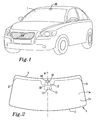
- Figure 1 shows an electrically heated window 1 according to the present invention assembled in a vehicle.
- An imaging device 10 is arranged to the window and partly to the inner ceiling of the vehicle.
- the imaging device 10 can be connected to processing unit such as a computer (not shown). During use, the imaging device captures images of e.g. the road. The processing unit thereafter analyses the images and identifies wanted or unwanted features. For instance, the processing unit can be arranged to identify the centre line of the road, the processing unit relates the position of the centre line with the position of the vehicle and can dependent upon the result of the analysis, initiate an action. Such an action can be a voice alert telling the driver to steer the vehicle to a safe position, initiate alert light signals to other drivers, correct the steering of the vehicle directly, or the like. Any action is possible within the boundaries of the present invention.
- processing unit such as a computer (not shown).
- the imaging device captures images of e.g. the road.
- the processing unit thereafter analyses the images and identifies wanted or unwanted features. For instance, the processing unit can be arranged to identify the centre line of the road, the processing unit relates the position of the centre line with the position of the vehicle and can dependent upon the result of the analysis, initiate an
- the window 1 comprises an interior and an exterior side 1 a, 1 b, a first and a second edge 2, 3 and an upper and a lower edge 4, 5.
- the interior side 1 a of the window 1 is intended to be facing towards the interior of the vehicle while the exterior side 1 b of the window 1, is intended to face away from the interior of the vehicle.
- the imaging device 10 is arranged on the interior side 1 a of the window 1 in the near proximity of the upper edge 4 of the window 1. The image device 10 receives the image through a viewing area 11 on the window.
- the viewing area 11 is the area through which the projected image is received by the imaging device through the window, i.e. the area through which the imaging device sees an object through the window.
- the viewing area 11 comprises a first and a second edge 12, 13 and an upper and a lower edge 14, 15.
- upper and lower are relative terms and should be related to a vehicle positioned on its wheels (if present) in a normal and a ready to use fashion. In this sense the upper edge 13 of the viewing area 11 is intended to be closer to the roof of the vehicle while the lower edge 14 of the viewing area 11 is intended to be closer to the ground.
- the window 1 has a centre line 6 which extends vertically between the upper and lower edges 14, 15 of the window 1.
- the window 1 has substantially mirror symmetry about the centre line 6.
- the imaging device 10 is arranged on the interior side 1 a of the window 1 in the near proximity of the upper edge 4 of the window 1. It is further arranged so that the centre line 6 crosses the centre of the viewing area 11 in a vertical manner between the upper and lower edge 14, 15 of the viewing area 11.
- the window 1 and the viewing area 11 is provided with a resistance heating element to keep the at least the viewing area 11 free from ice and moisture.
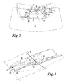
- Figure 3 shows the present invention in the form of parts of a window 1, an imaging device 10 and a resistance heating element 20, with a view straight into the imaging device 10.
- the imaging device 10 is equipped with a lens 16.
- a glare protection device 17 Arranged in a tray like configuration to the lens is a glare protection device 17, to prevent unwanted light reflections to enter the lens.
- the viewing area 11 is illustrated as a dotted line which in this embodiment of the present invention substantially corresponds to the form of the glare protection device 30.
- a resistance heating element 20 in the form of a silver and cupper based conducting wire 21 extends across the viewing area 11 along an arc shaped path between the first and second side 12, 13 of the viewing area 11.
- the arc shaped path along which the resistance heating element 20 extends is equal or less than a half wave length. This feature minimizes the amount of possible glare points along the resistance heating element 20. In practice only one glare point per crossing point is achieved in this way while still maintaining a form on the resistance heating element which minimizes the risk of the imaging device and its connected sensor device to miss interpret the resistance heating element as being a part of the image captured by the imaging device and thereby to also to miss interpret the resistance heating element as an object which requires an analysis.
- the arc shaped paths can be seen with a base B and a point P wherein the point P points towards the lower edge 15 of the viewing area 11 and the base B is arranged towards the upper edge 14 of the viewing area 11, however in an alternatively embodiment of the present invention, the point P of the arc shapes paths can point towards the upper side 14 of the viewing area 11 and the base B towards the lower edge 15 of the viewing area 11.
- FIG 4 shows the embodiment of the present invention shown in figure 3 in perspective.
- the window 1 is only partly illustrated for clarity reasons.
- the viewing area 11 is shown with dotted lines and is for clarity reasons illustrated slightly displaced with respect to the conducting wire 21.
- the glare protection device 17 which is substantially a tray like configuration comprises an opening 30 at one end at which the imaging device 10 is arranged. From the opening 30 of the glare protection device are a first and a second side wall 31, 32 arranged on either side of a bottom 30, the first and the second side wall extends from the opening 30 and merges with the bottom 33 of the glare protection device 17 at the far end of the glare protection device 17 opposite the opening 30.
- the configuration of the glare protection device 17 permits the glare protection device 17 to be attached to the interior side of a window, preferably so that the imaging device is arranged with an angle between 2-10 ° more preferably between 2-6 °, with respect to a horizontal plane.
- the glare protection device 17 prevents unwanted sun reflections to enter the imaging device, it further enables a quick and easy assembly of the imaging device with the window and the vehicle.
- the glare protection device 17 substantially defines the viewing area 11, this is advantageous because unwanted sun reflection is reduced to a minimum.
- figure 5 shows an embodiment in which the conducting wire 21 starts at the upper side 14 of the viewing area 11 along a first arc shaped 22 path across the viewing area, the first arc shaped path 22 has a radius R1.
- the first arc shaped path diverges into a path substantially parallel with the first and second edge 12, 13 of the viewing area outside the viewing area 11 to thereafter return back across the viewing area 11 along a second arc shaped path 23 with a radius R2, and so forth.
- the third arc shaped path 24 exhibit a radius R3, the forth arc shaped path a radius R4, the fifth arc shaped path a radius R5, the sixth arc shaped path a radius R6, etc.
- the resistance heating element 20, and specifically the conducting wire 21, is preferably made of silver and cupper based material with a thickness of about 0.1-0.5 mm, preferably between 0.2-0.4 mm.
- the resistance heating element 20 is naturally connected to the vehicle electrical system when assembled with a vehicle. Such a connection is conventional and do not need to be described in greater detail.
Landscapes
- Engineering & Computer Science (AREA)
- Mechanical Engineering (AREA)
- Automation & Control Theory (AREA)
- Surface Heating Bodies (AREA)
- Fittings On The Vehicle Exterior For Carrying Loads, And Devices For Holding Or Mounting Articles (AREA)
Priority Applications (3)
| Application Number | Priority Date | Filing Date | Title |
|---|---|---|---|
| EP07122842A EP2071901B1 (de) | 2007-12-11 | 2007-12-11 | Fenster mit Widerstandserwärmungselement |
| CN200810175542.7A CN101459991B (zh) | 2007-12-11 | 2008-11-07 | 具有电阻加热元件的窗 |
| US12/331,012 US7731373B2 (en) | 2007-12-11 | 2008-12-09 | Window with resistance heating element |
Applications Claiming Priority (1)
| Application Number | Priority Date | Filing Date | Title |
|---|---|---|---|
| EP07122842A EP2071901B1 (de) | 2007-12-11 | 2007-12-11 | Fenster mit Widerstandserwärmungselement |
Publications (2)
| Publication Number | Publication Date |
|---|---|
| EP2071901A1 true EP2071901A1 (de) | 2009-06-17 |
| EP2071901B1 EP2071901B1 (de) | 2012-08-15 |
Family
ID=39322547
Family Applications (1)
| Application Number | Title | Priority Date | Filing Date |
|---|---|---|---|
| EP07122842A Active EP2071901B1 (de) | 2007-12-11 | 2007-12-11 | Fenster mit Widerstandserwärmungselement |
Country Status (3)
| Country | Link |
|---|---|
| US (1) | US7731373B2 (de) |
| EP (1) | EP2071901B1 (de) |
| CN (1) | CN101459991B (de) |
Cited By (2)
| Publication number | Priority date | Publication date | Assignee | Title |
|---|---|---|---|---|
| EP2206601A1 (de) * | 2009-01-08 | 2010-07-14 | Saint Gobain Glass France | Scheibe mit einem Funktionselement |
| EP3228508A1 (de) * | 2016-04-06 | 2017-10-11 | Toyota Jidosha Kabushiki Kaisha | Fotografievorrichtung für fahrzeug |
Families Citing this family (45)
| Publication number | Priority date | Publication date | Assignee | Title |
|---|---|---|---|---|
| EP2334141A1 (de) * | 2009-12-11 | 2011-06-15 | Saint-Gobain Glass France | Beschichtete Scheibe mit beheizbarem Kommunikationsfenster |
| DE102011103340A1 (de) * | 2011-06-03 | 2012-12-06 | Continental Automotive Gmbh | Vorrichtung mit optischem Sensorsystem und Antibeschlaglösung |
| EP2823689B2 (de) * | 2012-03-05 | 2025-01-29 | Saint-Gobain Glass France | Scheibenanordnung mit elektrisch beheizbarer streulichtblende |
| US9992820B2 (en) * | 2012-03-12 | 2018-06-05 | Cornelis Christianus Pys | Vehicle glass removal system and method |
| US9199574B2 (en) | 2012-09-11 | 2015-12-01 | Gentex Corporation | System and method for detecting a blocked imager |
| US9137856B2 (en) | 2012-11-19 | 2015-09-15 | Fca Us Llc | Apparatus and methods for unfreezing vehicle door window from window seal |
| JP5949490B2 (ja) * | 2012-11-20 | 2016-07-06 | トヨタ自動車株式会社 | 車両用センサ搭載構造及びシステム連携方法 |
| US9395538B2 (en) | 2014-09-26 | 2016-07-19 | Delphi Technologies, Inc. | Vehicle imager assembly with localized window defogging |
| WO2016105674A1 (en) * | 2014-12-22 | 2016-06-30 | Illinois Tool Works Inc. | Dual plane heater for vehicle sensor system |
| JP6304205B2 (ja) * | 2015-11-11 | 2018-04-04 | トヨタ自動車株式会社 | 車載撮像装置 |
| JP6787776B2 (ja) * | 2015-12-22 | 2020-11-18 | 日本板硝子株式会社 | ウインドシールド |
| JP6558262B2 (ja) * | 2016-02-15 | 2019-08-14 | トヨタ自動車株式会社 | 周辺監視装置用のヒータ構造 |
| JP6555190B2 (ja) * | 2016-05-18 | 2019-08-07 | トヨタ自動車株式会社 | 車両用撮影装置 |
| JP6515871B2 (ja) * | 2016-05-31 | 2019-05-22 | トヨタ自動車株式会社 | ウィンドウガラス加熱装置 |
| USD803118S1 (en) * | 2016-11-02 | 2017-11-21 | Ford Global Technologies, Llc | Vehicle windshield |
| USD814371S1 (en) * | 2016-11-02 | 2018-04-03 | Ford Global Technologies, Llc | Vehicle windshield |
| USD805977S1 (en) * | 2016-12-19 | 2017-12-26 | Ford Global Technologies, Llc | Vehicle windshield |
| USD805978S1 (en) * | 2016-12-19 | 2017-12-26 | Ford Global Technologies, Llc | Vehicle windshield |
| US10986700B2 (en) | 2017-03-09 | 2021-04-20 | Aptiv Technologies Limited | Sensor assembly with integral defroster/defogger |
| JP6953182B2 (ja) * | 2017-05-23 | 2021-10-27 | 東京コスモス電機株式会社 | 発熱装置 |
| JP7092145B2 (ja) * | 2017-10-20 | 2022-06-28 | Agc株式会社 | 車両用合わせガラス |
| JP7311948B2 (ja) * | 2017-11-29 | 2023-07-20 | 日本板硝子株式会社 | ウインドシールド |
| JP7125261B2 (ja) * | 2017-12-12 | 2022-08-24 | 小島プレス工業株式会社 | 車両用撮影装置 |
| JP7006258B2 (ja) * | 2017-12-27 | 2022-01-24 | トヨタ自動車株式会社 | 車両用撮影装置及び加熱装置 |
| JP6939536B2 (ja) * | 2017-12-27 | 2021-09-22 | トヨタ自動車株式会社 | 車両用撮影装置 |
| EP3515153B1 (de) * | 2018-01-19 | 2020-07-29 | Axis AB | Kamera mit heizanordnung und verfahren zum erwärmen eines kamerasichtfensters |
| JP7192862B2 (ja) * | 2018-05-30 | 2022-12-20 | Agc株式会社 | ガラス |
| JP7044692B2 (ja) * | 2018-12-20 | 2022-03-30 | 本田技研工業株式会社 | 移動体用撮影システム |
| JP7184653B2 (ja) * | 2019-01-09 | 2022-12-06 | 本田技研工業株式会社 | 移動体 |
| JP7140698B2 (ja) * | 2019-03-05 | 2022-09-21 | 本田技研工業株式会社 | 曇り抑制装置およびその制御方法 |
| JP7066650B2 (ja) * | 2019-03-05 | 2022-05-13 | 本田技研工業株式会社 | 曇り抑制装置およびその制御方法 |
| JP7078578B2 (ja) * | 2019-06-10 | 2022-05-31 | 本田技研工業株式会社 | 輸送機器及び車両 |
| JP7559757B2 (ja) | 2019-07-25 | 2024-10-02 | Agc株式会社 | 車両用ガラス装置 |
| CN114391302B (zh) * | 2019-08-02 | 2025-03-18 | 东京Cosmos电机株式会社 | 加热器装置及车辆用拍摄装置 |
| US11470265B2 (en) * | 2019-12-16 | 2022-10-11 | Plusai, Inc. | System and method for sensor system against glare and control thereof |
| US11724669B2 (en) | 2019-12-16 | 2023-08-15 | Plusai, Inc. | System and method for a sensor protection system |
| US11650415B2 (en) | 2019-12-16 | 2023-05-16 | Plusai, Inc. | System and method for a sensor protection mechanism |
| US11754689B2 (en) | 2019-12-16 | 2023-09-12 | Plusai, Inc. | System and method for detecting sensor adjustment need |
| US11738694B2 (en) | 2019-12-16 | 2023-08-29 | Plusai, Inc. | System and method for anti-tampering sensor assembly |
| US11077825B2 (en) | 2019-12-16 | 2021-08-03 | Plusai Limited | System and method for anti-tampering mechanism |
| JP7428119B2 (ja) * | 2020-12-10 | 2024-02-06 | トヨタ自動車株式会社 | 防曇装置 |
| US11772667B1 (en) | 2022-06-08 | 2023-10-03 | Plusai, Inc. | Operating a vehicle in response to detecting a faulty sensor using calibration parameters of the sensor |
| US12441276B2 (en) * | 2022-10-13 | 2025-10-14 | Austin Kemp | Vehicle wheel well heating system |
| CN219619059U (zh) | 2023-04-19 | 2023-09-01 | Agc株式会社 | 除霜装置 |
| GB2638690A (en) * | 2024-02-27 | 2025-09-03 | Jaguar Land Rover Ltd | Vehicle windscreen heater |
Citations (2)
| Publication number | Priority date | Publication date | Assignee | Title |
|---|---|---|---|---|
| US5804817A (en) * | 1993-01-13 | 1998-09-08 | Robert Bosch Gmbh | Sensor device for detecting the degree of wetting and/or contamination of windows, especially windshields of motor vehicles |
| EP1605729A2 (de) | 2004-04-15 | 2005-12-14 | Pilkington Plc | Elektrische beheizte Scheibe. |
Family Cites Families (12)
| Publication number | Priority date | Publication date | Assignee | Title |
|---|---|---|---|---|
| US2773162A (en) * | 1954-01-14 | 1956-12-04 | Boeing Co | Anti-icing of windows by dielectric heating |
| DE1555053B1 (de) * | 1964-04-23 | 1970-04-30 | Saint Gobain | Verfahren zur Herstellung einer heizbaren Autoscheibe |
| US3888711A (en) * | 1970-06-19 | 1975-06-10 | Wilhelm Breitner | Method of applying metal filaments to surfaces |
| JPS4724681Y1 (de) * | 1970-12-18 | 1972-08-03 | ||
| US4127763A (en) * | 1975-04-17 | 1978-11-28 | Saint-Gobain Industries | Heated window with a moisture sensor having a high impedance |
| FR2473243A1 (fr) * | 1980-01-08 | 1981-07-10 | Saint Gobain Vitrage | Vitrage chauffant et dispositif de fabrication |
| US5638209A (en) * | 1994-02-14 | 1997-06-10 | Aisin Seiki Kabushiki Kaisha | Mirror apparatus |
| US5886321A (en) * | 1996-12-19 | 1999-03-23 | Ppg Industries, Inc. | Arrangement for heating the wiper rest area of a vehicle windshield |
| DE19751423A1 (de) * | 1997-11-20 | 1999-06-02 | Bosch Gmbh Robert | Scheibenheizung |
| US6316746B1 (en) * | 2000-06-23 | 2001-11-13 | Carolyn M. Golston | Defrosting assembly for a mirror of a vehicle |
| DE10126869A1 (de) * | 2001-06-01 | 2002-12-19 | Saint Gobain Sekurit D Gmbh | Elektrisch beheizbare Scheibe |
| US6559419B1 (en) * | 2001-08-03 | 2003-05-06 | Centre Luxembourgeois De Recherches Pour Le Verre Et La Ceramique S.A. (C.R.V.C.) | Multi-zone arrangement for heatable vehicle window |
-
2007
- 2007-12-11 EP EP07122842A patent/EP2071901B1/de active Active
-
2008
- 2008-11-07 CN CN200810175542.7A patent/CN101459991B/zh active Active
- 2008-12-09 US US12/331,012 patent/US7731373B2/en active Active
Patent Citations (2)
| Publication number | Priority date | Publication date | Assignee | Title |
|---|---|---|---|---|
| US5804817A (en) * | 1993-01-13 | 1998-09-08 | Robert Bosch Gmbh | Sensor device for detecting the degree of wetting and/or contamination of windows, especially windshields of motor vehicles |
| EP1605729A2 (de) | 2004-04-15 | 2005-12-14 | Pilkington Plc | Elektrische beheizte Scheibe. |
Cited By (2)
| Publication number | Priority date | Publication date | Assignee | Title |
|---|---|---|---|---|
| EP2206601A1 (de) * | 2009-01-08 | 2010-07-14 | Saint Gobain Glass France | Scheibe mit einem Funktionselement |
| EP3228508A1 (de) * | 2016-04-06 | 2017-10-11 | Toyota Jidosha Kabushiki Kaisha | Fotografievorrichtung für fahrzeug |
Also Published As
| Publication number | Publication date |
|---|---|
| US7731373B2 (en) | 2010-06-08 |
| EP2071901B1 (de) | 2012-08-15 |
| CN101459991A (zh) | 2009-06-17 |
| US20090147360A1 (en) | 2009-06-11 |
| CN101459991B (zh) | 2014-04-09 |
Similar Documents
| Publication | Publication Date | Title |
|---|---|---|
| EP2071901B1 (de) | Fenster mit Widerstandserwärmungselement | |
| US10486599B2 (en) | Rearview vision system for vehicle | |
| US11851006B2 (en) | Multi-camera vehicular video display system | |
| US10384610B2 (en) | Rearview vision system for vehicle | |
| US11972597B2 (en) | Vehicular driver monitoring system with camera view optimization | |
| US20240314443A1 (en) | Vehicular camera module | |
| US10678018B2 (en) | Camera for vehicle vision system with replaceable lens | |
| JP3262265B2 (ja) | 光学的道路探測システム | |
| EP2022676B1 (de) | Kamera zur Montage in einem Kraftfahrzeug | |
| US7026930B2 (en) | Process and device for adjusting a movable motor vehicle part | |
| US11738696B2 (en) | Device for sensing the vehicle surroundings of a vehicle | |
| US20130155236A1 (en) | Camera-mirror system for motor vehicle | |
| US20160264063A1 (en) | Vehicle vision system with camera viewing through windshield | |
| EP3802175B1 (de) | Fahrzeug mit einer äusseren sonnenblende und einer daran verbundenen sensoreinheit | |
| US12340546B2 (en) | Vehicular occupant monitoring system using centralized camera with expanded view | |
| JP2018188125A (ja) | カメラ装置 | |
| JP4520661B2 (ja) | 車両用周辺監視装置 | |
| JP2006137209A (ja) | 車両用防眩装置 | |
| WO2004065176A1 (de) | Halterung für die spiegelfläche eines innenrückspiegels, kamera umfassend eine derartige halterung sowie mit einer derartigen kamera ausgestattetes kraftfahrzeug | |
| CN109835259B (zh) | 车辆成像系统 | |
| WO2025051135A1 (zh) | 舱内多传感器集成装置及汽车 | |
| EP1705063A1 (de) | Überwachungssystem für Toten Winkel |
Legal Events
| Date | Code | Title | Description |
|---|---|---|---|
| PUAI | Public reference made under article 153(3) epc to a published international application that has entered the european phase |
Free format text: ORIGINAL CODE: 0009012 |
|
| AK | Designated contracting states |
Kind code of ref document: A1 Designated state(s): AT BE BG CH CY CZ DE DK EE ES FI FR GB GR HU IE IS IT LI LT LU LV MC MT NL PL PT RO SE SI SK TR |
|
| AX | Request for extension of the european patent |
Extension state: AL BA HR MK RS |
|
| 17P | Request for examination filed |
Effective date: 20091028 |
|
| 17Q | First examination report despatched |
Effective date: 20091126 |
|
| AKX | Designation fees paid |
Designated state(s): DE GB SE |
|
| RAP1 | Party data changed (applicant data changed or rights of an application transferred) |
Owner name: VOLVO CAR CORPORATION |
|
| GRAP | Despatch of communication of intention to grant a patent |
Free format text: ORIGINAL CODE: EPIDOSNIGR1 |
|
| GRAS | Grant fee paid |
Free format text: ORIGINAL CODE: EPIDOSNIGR3 |
|
| GRAA | (expected) grant |
Free format text: ORIGINAL CODE: 0009210 |
|
| AK | Designated contracting states |
Kind code of ref document: B1 Designated state(s): DE GB SE |
|
| REG | Reference to a national code |
Ref country code: GB Ref legal event code: FG4D |
|
| REG | Reference to a national code |
Ref country code: DE Ref legal event code: R096 Ref document number: 602007024729 Country of ref document: DE Effective date: 20121011 |
|
| REG | Reference to a national code |
Ref country code: SE Ref legal event code: TRGR |
|
| PLBE | No opposition filed within time limit |
Free format text: ORIGINAL CODE: 0009261 |
|
| STAA | Information on the status of an ep patent application or granted ep patent |
Free format text: STATUS: NO OPPOSITION FILED WITHIN TIME LIMIT |
|
| 26N | No opposition filed |
Effective date: 20130516 |
|
| REG | Reference to a national code |
Ref country code: DE Ref legal event code: R097 Ref document number: 602007024729 Country of ref document: DE Effective date: 20130516 |
|
| PGFP | Annual fee paid to national office [announced via postgrant information from national office to epo] |
Ref country code: SE Payment date: 20191113 Year of fee payment: 13 |
|
| PGFP | Annual fee paid to national office [announced via postgrant information from national office to epo] |
Ref country code: GB Payment date: 20191106 Year of fee payment: 13 |
|
| REG | Reference to a national code |
Ref country code: SE Ref legal event code: EUG |
|
| GBPC | Gb: european patent ceased through non-payment of renewal fee |
Effective date: 20201211 |
|
| PG25 | Lapsed in a contracting state [announced via postgrant information from national office to epo] |
Ref country code: SE Free format text: LAPSE BECAUSE OF NON-PAYMENT OF DUE FEES Effective date: 20201212 Ref country code: GB Free format text: LAPSE BECAUSE OF NON-PAYMENT OF DUE FEES Effective date: 20201211 |
|
| PGFP | Annual fee paid to national office [announced via postgrant information from national office to epo] |
Ref country code: DE Payment date: 20241119 Year of fee payment: 18 |