EP3515153B1 - Kamera mit heizanordnung und verfahren zum erwärmen eines kamerasichtfensters - Google Patents
Kamera mit heizanordnung und verfahren zum erwärmen eines kamerasichtfensters Download PDFInfo
- Publication number
- EP3515153B1 EP3515153B1 EP18152539.5A EP18152539A EP3515153B1 EP 3515153 B1 EP3515153 B1 EP 3515153B1 EP 18152539 A EP18152539 A EP 18152539A EP 3515153 B1 EP3515153 B1 EP 3515153B1
- Authority
- EP
- European Patent Office
- Prior art keywords
- camera
- viewing window
- heating
- heating arrangement
- conductor
- Prior art date
- Legal status (The legal status is an assumption and is not a legal conclusion. Google has not performed a legal analysis and makes no representation as to the accuracy of the status listed.)
- Active
Links
Images


Classifications
-
- G—PHYSICS
- G02—OPTICS
- G02B—OPTICAL ELEMENTS, SYSTEMS OR APPARATUS
- G02B27/00—Optical systems or apparatus not provided for by any of the groups G02B1/00 - G02B26/00, G02B30/00
- G02B27/0006—Optical systems or apparatus not provided for by any of the groups G02B1/00 - G02B26/00, G02B30/00 with means to keep optical surfaces clean, e.g. by preventing or removing dirt, stains, contamination, condensation
-
- G—PHYSICS
- G03—PHOTOGRAPHY; CINEMATOGRAPHY; ANALOGOUS TECHNIQUES USING WAVES OTHER THAN OPTICAL WAVES; ELECTROGRAPHY; HOLOGRAPHY
- G03B—APPARATUS OR ARRANGEMENTS FOR TAKING PHOTOGRAPHS OR FOR PROJECTING OR VIEWING THEM; APPARATUS OR ARRANGEMENTS EMPLOYING ANALOGOUS TECHNIQUES USING WAVES OTHER THAN OPTICAL WAVES; ACCESSORIES THEREFOR
- G03B17/00—Details of cameras or camera bodies; Accessories therefor
- G03B17/55—Details of cameras or camera bodies; Accessories therefor with provision for heating or cooling, e.g. in aircraft
-
- G—PHYSICS
- G03—PHOTOGRAPHY; CINEMATOGRAPHY; ANALOGOUS TECHNIQUES USING WAVES OTHER THAN OPTICAL WAVES; ELECTROGRAPHY; HOLOGRAPHY
- G03B—APPARATUS OR ARRANGEMENTS FOR TAKING PHOTOGRAPHS OR FOR PROJECTING OR VIEWING THEM; APPARATUS OR ARRANGEMENTS EMPLOYING ANALOGOUS TECHNIQUES USING WAVES OTHER THAN OPTICAL WAVES; ACCESSORIES THEREFOR
- G03B17/00—Details of cameras or camera bodies; Accessories therefor
- G03B17/02—Bodies
- G03B17/04—Bodies collapsible, foldable or extensible, e.g. book type
-
- G—PHYSICS
- G05—CONTROLLING; REGULATING
- G05D—SYSTEMS FOR CONTROLLING OR REGULATING NON-ELECTRIC VARIABLES
- G05D23/00—Control of temperature
- G05D23/19—Control of temperature characterised by the use of electric means
- G05D23/20—Control of temperature characterised by the use of electric means with sensing elements having variation of electric or magnetic properties with change of temperature
-
- H—ELECTRICITY
- H04—ELECTRIC COMMUNICATION TECHNIQUE
- H04N—PICTORIAL COMMUNICATION, e.g. TELEVISION
- H04N23/00—Cameras or camera modules comprising electronic image sensors; Control thereof
- H04N23/50—Constructional details
-
- H—ELECTRICITY
- H04—ELECTRIC COMMUNICATION TECHNIQUE
- H04N—PICTORIAL COMMUNICATION, e.g. TELEVISION
- H04N23/00—Cameras or camera modules comprising electronic image sensors; Control thereof
- H04N23/50—Constructional details
- H04N23/51—Housings
-
- H—ELECTRICITY
- H04—ELECTRIC COMMUNICATION TECHNIQUE
- H04N—PICTORIAL COMMUNICATION, e.g. TELEVISION
- H04N23/00—Cameras or camera modules comprising electronic image sensors; Control thereof
- H04N23/90—Arrangement of cameras or camera modules, e.g. multiple cameras in TV studios or sports stadiums
-
- H—ELECTRICITY
- H05—ELECTRIC TECHNIQUES NOT OTHERWISE PROVIDED FOR
- H05B—ELECTRIC HEATING; ELECTRIC LIGHT SOURCES NOT OTHERWISE PROVIDED FOR; CIRCUIT ARRANGEMENTS FOR ELECTRIC LIGHT SOURCES, IN GENERAL
- H05B3/00—Ohmic-resistance heating
- H05B3/84—Heating arrangements specially adapted for transparent or reflecting areas, e.g. for demisting or de-icing windows, mirrors or vehicle windshields
- H05B3/86—Heating arrangements specially adapted for transparent or reflecting areas, e.g. for demisting or de-icing windows, mirrors or vehicle windshields the heating conductors being embedded in the transparent or reflecting material
-
- G—PHYSICS
- G03—PHOTOGRAPHY; CINEMATOGRAPHY; ANALOGOUS TECHNIQUES USING WAVES OTHER THAN OPTICAL WAVES; ELECTROGRAPHY; HOLOGRAPHY
- G03B—APPARATUS OR ARRANGEMENTS FOR TAKING PHOTOGRAPHS OR FOR PROJECTING OR VIEWING THEM; APPARATUS OR ARRANGEMENTS EMPLOYING ANALOGOUS TECHNIQUES USING WAVES OTHER THAN OPTICAL WAVES; ACCESSORIES THEREFOR
- G03B2217/00—Details of cameras or camera bodies; Accessories therefor
- G03B2217/007—Details of energy supply or management
Definitions
- the present invention relates to a camera having a heating arrangement for heating a viewing window of the camera. It also relates to a method of heating a viewing window of a camera.
- a camera When cameras, and particularly monitoring cameras, are used outdoors, they are subject to environmental factors such as cold and moisture. In cold weather, ice may form on a viewing window of a monitoring camera, thereby obscuring or blocking the view of the camera.
- a camera In order to prevent formation of ice, or to remove ice that has formed, a camera may be provided with a built-in heater or fan. Such a heater or fan may be dedicated to heating just the viewing window, or it may be used for heating the entire camera housing. Heaters and fans may also be used for preventing dew formation on the viewing window in moist environments.
- An example of a camera housing provided with a fan may be found in US-6,061,087 .
- two fans are arranged in the camera housing for establishing a circulating air flow pattern around the monitoring camera.
- Other cameras have heaters similar to the ones used for heating rear windows of cars. These may be made of thin, electrically conductive threads attached to the window. When current is applied to the threads, the threads heat up, and thereby also heat the window.
- Other cameras such as the one described in US 2011/0115972 , have a coating applied to the surface of the window. Similar to the previously mentioned threads, the coating is electrically conductive and may thus be heated by application of current.
- a problem with the known solutions is that they may be either bulky or highly energy consuming, or both. Fans take up space, and are difficult to fit inside a small camera housing. Additionally, they have movable parts that wear with use and may need to be replaced during the life of the camera. Further, heating the viewing window using threads or layers attached to the window requires a lot of electric power, thereby increasing the total power consumption of the camera. This may be problematic especially for cameras powered by Power over Ethernet (PoE), as there are limits to how much power can be provided under the PoE standards. Heating may require a lot of power particularly in cameras with relatively large viewing windows. This is the case, e.g., in cameras having several camera heads arranged in one camera housing and inside one dome or viewing window, such as panoramic monitoring cameras. Examples of such cameras are the Q6000-E and P3707-PE marketed by the applicant's daughter company Axis Communications AB.
- US 2012/0170119 describes a defogging and defrosting device for a protective lens of a camera. This device is arranged on the camera body, and this is described as being preferable to arranging the device on the protective lens, making it easier to remove the protective lens for adjusting focus.
- US 2017/0205686 describes a camera having a dome bubble.
- a heat-emitting film is arranged on the lens unit of the camera, and is adapted to radiate heat for heating the dome bubble.
- a sealing member makes it possible to contain the radiated heat.
- An object of the present invention is to provide a camera in which heating of the viewing window may be performed energy efficiently.
- Another object is to provide a camera in which heating of the window does not require a bulky heater or fan.
- a camera comprising: a movable camera head, a transparent viewing window through which the camera head is arranged to capture images, and a heating arrangement for heating the viewing window, wherein the viewing window comprises an electrical conductor, and the heating arrangement comprises: an electrical contact device for contacting the conductor and applying an electric current to the conductor in a portion of the viewing window, thereby heating the conductor in the portion of the viewing window, and a movement device for movement of the heating arrangement in coordination with a movement of the camera head.
- the heating arrangement By making the heating arrangement movable in coordination with the camera head, it is possible to ensure that the portion of the viewing window through which the camera head is to capture images is heated for preventing formation of ice or dew, or for removal of ice or dew that has formed on the viewing window. It should be noted that although reference is made to dew and dew formation, condensation of any liquid, not just water, may be prevented or removed in the same way. Still, this will be referred to as dew and dew formation throughout this description.
- viewing window may refer to a planar viewing window, as well as a curved viewing window, such as a dome of, e.g., spherical, semi spherical, annular or toroidal shape.
- portion of the viewing window is meant a portion which is smaller than the entire viewing window.
- the conductor may be a conductive layer applied on the viewing window.
- a conductive layer By applying a conductive layer on the viewing window, it may easily be ensured that a portion of the viewing window at any given location may be heated.
- the conductive layer may be formed in numerous ways, e.g., as a film attached to a surface of the viewing window or as a coating applied on a surface of the viewing window. It may also be formed as a layer in the material of the viewing window.
- the conductive layer may be applied on an inside of the viewing window.
- the conductive layer may be protected from environmental factors, such as rain, snow and dust. Further, the conductive layer may be protected from vandalism and from damage by, e.g., perching birds or cleaning tools. Additionally, the heating arrangement may also efficiently be arranged protected inside the viewing window.
- the conductive layer is a coating.
- the coating may be applied in any suitable way, such as painting, spraying, sputter deposition, or vacuum metalizing.
- a coating may be applied in a production efficient manner, and may adapt to any shape of the viewing window.
- the coating may comprise indium tin oxide.
- Indium tin oxide, or ITO for short, is a widely used transparent coating. It is a good electrical conductor and is optically transparent. ITO is reflective to a large part of the infrared spectrum, but is transparent to near-infrared radiation (NIR). It is therefore suitable as a coating for digital cameras, as the image sensors used are generally sensitive not only to visible light, but also to NIR, making it possible to capture images also in low light.
- the electrical contact device comprises two flexible contact bars arranged to be applied on a surface of the viewing window, defining between them the portion of the viewing window.
- the movement device may comprise a frame which carries the electrical contact device and which is attached to a holder holding the camera head. This may provide a mechanically simple way of ensuring that the heating arrangement may be moved with the camera head, such that a portion of the viewing window in front of the camera head may be heated.
- the camera further comprises a temperature sensor arranged to sense a temperature of the viewing window.
- a temperature sensor makes it possible to ascertain when heating is needed and when heating may be switched off.
- the camera may comprise two or more camera heads and a respective heating arrangement associated with each camera head.
- Such cameras generally have a large viewing window, and therefore power savings may be made by heating only a portion of the viewing window at the capturing position of each camera head.
- the camera heads are movable in a panning direction. Such cameras may be used for capturing panoramic images of a monitored scene.
- the abovementioned objects are achieved, in full or at least in part, by a method of heating a viewing window of a camera, the camera comprising a movable camera head, and a heating arrangement for heating the viewing window, wherein the viewing window is transparent and comprises an electrical conductor, and the heating arrangement comprises: an electrical contact device for contacting the conductor, and a movement device for movement of the heating arrangement in coordination with a movement of the camera head, the method comprising: moving the camera head to a capturing position, moving the heating arrangement to the capturing position, and applying an electric current to the conductor in a portion of the viewing window at the capturing position, thereby heating the conductor in the portion of the viewing window at the capturing position.
- the step of moving the heating arrangement may be performed by moving the camera head or vice versa. In this manner, it is possible to ensure that the heating arrangement is correctly placed for heating the viewing window at the capturing position.
- the method may further comprise sensing a temperature of the viewing window, comparing the sensed temperature to a first temperature threshold, and if the sensed temperature is below the first temperature threshold, applying the electric current to the conductor.
- the first temperature threshold may be set such that dew formation may be avoided or such that dew may be removed.
- the method further comprises sensing a temperature of the viewing window, comparing the sensed temperature to a second temperature threshold, and if the sensed temperature is above the second temperature threshold, interrupting application of the electric current to the conductor.
- the second temperature threshold may be chosen such that heating of the position of the viewing window may be switched off when the temperature of the viewing window is above a temperature where there is a risk of ice formation or dew formation. In this manner, power may be saved by not heating the viewing window for unnecessarily long periods of time. Further, once the viewing window has reached a temperature necessary for removing or preventing ice or dew, continued heating may risk damaging the camera or distorting the captured images.
- a camera 1 is shown.
- the camera 1 has a housing 2 and a generally annular viewing window 3.
- the viewing window 3 is transparent, such that the camera heads may capture images of the surrounding scene through the viewing window 3.
- Each camera head 4 is carried by a camera holder 5, which is arranged on a circular mounting rail 6, as may be seen in Fig. 2 . In the interest of clarity, only one of the camera heads 4 is shown in Fig. 2 .
- the camera holders 5, and thereby the camera heads 4, are movable along the mounting rail 6, such that at installation of the camera 1, each camera head 4 may be placed in a desired capturing position, making it possible to capture images of a desired part of the surrounding scene.
- the four camera heads 4 may be placed equidistantly around the mounting rail, such that they together may cover a 360° field of view.
- the camera heads may also be placed in other positions along the mounting rail as desired. For instance, there may be objects in the scene blocking the view, such that it is preferable to place the camera heads at other angular distances from each other.
- the camera holders 5 may be locked in place on the mounting rail, e.g., by magnetic force, such as described in applicant's EP-2 887 328 . In this manner, the camera heads may easily be positioned in suitable positions during mounting of the camera, and they may then be securely held in those positions during operation.
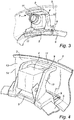
- the heating arrangement 7 On each camera holder 5, a heating arrangement 7 is arranged. This may be seen in closer detail in Fig. 3 .
- the heating arrangement 7 has a movement device 8 making it possible to move the heating arrangement 7 as the camera head 4 is moved. By arranging the heating arrangement 7 on the camera holder 5 it is possible to move the heating arrangement 7 by moving the camera head 4 to a desired capturing position. It is also possible to do this vice versa, i.e. to move the camera head 4 by moving the heating arrangement 7.
- the heating arrangement 7 comprises an electrical contact device 9, which in this example takes the form of a frame 10 carrying two contact bars 11 arranged to be placed in contact with the inside surface of the viewing window 3.
- the contact bars 11 have a relatively rigid core, covered by a rubber or elastomeric layer providing flexibility, and an electrically conductive outer sleeve.
- Wiring 12 (indicated only in Fig. 1 ) is arranged for providing power from a power source (not shown) to the contact bars 11.
- the flexibility of the contact bars 11 makes it possible to achieve a good contact between the contact bars and the inside of the viewing window 3. Further, it reduces the risk of scratching the inside of the viewing window 3.
- the viewing window comprises an electrical conductor 13.
- the electrical conductor 13 is a coating of ITO.
- the coating 13 covers essentially the entire inside surface of the viewing window.
- resistance of the coating material will raise the temperature of the coating 13, and thereby also of the portion of the viewing window 3 which the coating 13 between the contact bars 11 covers.
- the camera 1 shown in Fig. 1 is a panoramic camera having four camera heads 4.
- the camera heads 4 may be moved freely along the mounting rail 6 to desired capturing positions and locked in place.
- the four camera heads 4 may be placed 90° apart, thereby enabling a total 360° field of view, depending on the individual field of view of each camera head 4.
- the viewing window 3 is quite large, especially compared to the combined viewing window area taken up by the camera heads 4. It may therefore be inefficient energy-wise to heat the entire viewing window for removing or preventing ice or dew.
- each heating arrangement 7 is movable in coordination with the respective camera head 4 makes it possible to heat just a portion of the viewing window 3 at the capturing position. In this manner, energy may be saved. Further, ice or dew may be removed quicker locally than if the whole viewing window were to be heated on the same power budget.
- FIG. 5 shows another panoramic camera 101, which has a viewing window that may be described as toroidal or donut-shaped. A viewing window or dome of this kind may be seen in applicant's EP-3 168 819 .
- the same reference numerals as in Figs 1-4 have been used, but with the addition of 100.
- the camera heads 104 may at installation of the camera 101 be moved to desired capturing positions and locked there for operation.
- Each heating arrangement 107 is moved with the respective camera head 104.
- By applying power to the contact bars 111 current may be applied to the coating 114 to heat the viewing window 103 locally at each capturing position.
- Fig. 6 shows a camera 201 having a more commonly used dome of a generally semi spherical shape.
- the camera head 204 may in the same way as in the two previously described embodiments be movable by panning and tilting at installation for achieving a desired field of view.
- the heating arrangement 207 is moved in coordination with the camera head 204, such that current may be applied to the coating 214 in a portion of the viewing window 203 at the capturing position for heating.
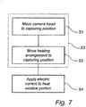
- This method may be used in any of the cameras 1, 101, 201 shown in the drawings, or in any other camera having a heating arrangement that is movable in coordination with a camera head of the camera.
- the camera head is moved to a capturing position (step S1).
- the heating arrangement is also moved to the capturing position (S2).
- the camera head and the heating arrangement are moved together to the capturing position, such that these two steps S1, S2 may be joined together in a single step S3.
- Current is applied by the electrical contact device to the coating on the viewing window (S4). In this manner, the coating is heated, and thereby the portion of the viewing window at the capturing position is heated, such that ice or dew formation may be prevented, or such that ice or dew may be removed.
- the camera may be provided with a temperature sensor.
- the temperature of the viewing window may be sensed, such that it is possible to determine if heating is necessary.
- the sensed temperature may be compared to a first temperature threshold indicative of a risk of ice formation.
- the first temperature threshold may be set to 0 °C. If the sensed temperature is below the first temperature threshold, application of current may be started, such that ice formation may be prevented or such that ice that has already been formed may be melted. It may also be desirable to determine when the heating may safely be switched off.
- a second temperature threshold may be set, which is indicative of little or no risk of ice formation. For instance, the second temperature threshold may be set to 1 °C.
- the sensed temperature may be compared to the second temperature threshold, and if the sensed temperature is above the second temperature threshold, the heating arrangement may be switched off, such that current application ceases.
- the heating arrangement may be switched off, such that current application ceases.
- the camera head whose viewing window portion is being heated may be in operation, whereas the other camera heads are switched off.
- the temperature sensor may be used for determining if heating for preventing or removing dew is needed, and for determining if such heating may be safely interrupted.
- a hygrometer for determining air humidity.
- a user of the camera may manually switch heating on and off.
- a timer may be used for controlling the heating.
- Image analysis may also be used for determining if there is ice or dew on the viewing window, and heating may be switched on automatically when such an event is detected. Similarly, heating may be switched off when image analysis indicates that there is no longer any ice or dew on the viewing window.
- a person skilled in the art can modify the above described embodiments in many ways and still use the advantages of the invention as shown in the embodiments above.
- another material may be used for the coating.
- a doped binary compound such as aluminium-doped zinc oxide, indium-doped zinc oxide, gallium-doped zinc oxide, or indium-doped cadmium oxide.
- a coating of carbon nanotubes may also be possible.
- a film of graphene may be used.
- Conductive polymers may also be used. These generally have a lower conductivity, but are less expensive than many other alternatives.
- Electrically conducting threads may instead be attached to a surface of the viewing window, similar to what is commonly used on rear windows of cars.
- particles of an electrically conductive material may be embedded in the material of the viewing window.
- a balance must here be struck between the desire to make the viewing window electrically conducting and a risk of lowering impact resistance of the viewing window, particularly if the camera is to be used where there is a risk of vandalism.
- the conductor is embedded in the viewing window material, the electrical contact device needs to be adapted, as it may not be possible to achieve direct electrical contact with the conductor. In such case, induction may be used. Induction may be useful also if direct contact with the viewing window is undesirable, such as in a PTZ camera, where the camera head in many situations moves frequently and quickly.
- a slightly different approach which is outside the scope of the present invention, would be to use not an electrical conductor in or on the viewing window, but a thermal conductor.
- IR absorbing particles could be embedded in the viewing window material, and a movable heating arrangement in the form of an IR emitter could be used for heating the IR absorbing particles and thereby a portion of the viewing window at the capturing position.
- the coating may be applied by sputter deposition. However, depending on the material used, it may also be possible to paint or spray the coating on the viewing window, or to apply the coating by, e.g., tape casting, laser sintering, or electron beam evaporation.
- the coating is on the inside of the viewing window, and so is the heating arrangement.
- the coating and the heating arrangement are protected inside the camera housing.
- the coating or film, as well as the heating arrangement on the outside of the viewing window. This may for instance be desirable if the camera housing is small and does not have room for the heating arrangement. It may also be an advantageous alternative if an existing camera is to be retrofitted with a film or coating and a heating arrangement. Permutations are also possible in which the coating or film is on the inside of the viewing window and the heating arrangement is on the outside, or vice versa.
- the film or coating on one side of the viewing window and to have conductive strips of material arranged at intervals along the edges of the viewing window and extending over the edges onto the other side of the viewing window for contact with the electrical contact device. It may here be noted that such an arrangement would be more useful in cameras having a viewing window with separate upper and lower edges, such as the annular viewing window in Fig. 1 , than in cameras having a viewing window in the form of a continuous dome, such as in Figs. 5 and 6 .
- the heating arrangement may be integrated in the camera holder, but it may also be removably attached to the camera holder or entirely separate from the camera holder. If the heating arrangement is removable, it may be removed if the camera is used in an environment where there is no need for heating, such as in a dry indoor environment. If the camera is later moved to another location, where heating is needed, the heating arrangement may be replaced.
- the heating arrangement may also be delivered separately for retrofitting or for mounting at installation of the camera.
- the contact bars have been described as having a flexible layer of rubber or elastomeric material and being covered by an electrically conducting sleeve. They may as well be made of an electrically conductive rubber or elastomeric material.
- the camera heads are manually movable during installation.
- the cameras may also be motorised, such that the camera heads may be adjusted remotely at installation.
- the invention may provide most advantage in the case of cameras having camera heads that are movable only at installation, where each camera head takes up just a part of the available viewing window area during operation, it may also be used to advantage in cameras having camera heads that are movable during operation.
- Such cameras may be referred to as PT cameras or PTZ cameras depending on if they are capable of just panning and tilting (PT), or if they are additionally capable of zooming (PTZ).
- the invention may be of particular use if the camera head moves relatively slowly or infrequently, or if it is pointed in one particular direction more often than in other directions.
Landscapes
- Physics & Mathematics (AREA)
- General Physics & Mathematics (AREA)
- Engineering & Computer Science (AREA)
- Aviation & Aerospace Engineering (AREA)
- Multimedia (AREA)
- Signal Processing (AREA)
- Optics & Photonics (AREA)
- Automation & Control Theory (AREA)
- Accessories Of Cameras (AREA)
- Studio Devices (AREA)
- Structure And Mechanism Of Cameras (AREA)
- Cameras Adapted For Combination With Other Photographic Or Optical Apparatuses (AREA)
- Camera Bodies And Camera Details Or Accessories (AREA)
- Investigating Or Analyzing Materials Using Thermal Means (AREA)
- Radiation Pyrometers (AREA)
Claims (14)
- Kamera, umfassend:einen beweglichen Kamerakopf (4),ein transparentes Sichtfenster (3), durch das der Kamerakopf (4) vorgesehen ist Bilder aufzunehmen, undeine Heizanordnung (7) zum Heizen des Sichtfensters (3),eine Bewegungsvorrichtung (8) zum Bewegen der Heizanordnung (7) in Abstimmung mit einer Bewegung des Kamerakopfes (4),daduch gekennzeichnetdass das Sichtfenster (3) einen elektrischen Leiter (13) umfasst, unddass die Heizanordnung (7) eine elektrische Kontaktvorrichtung (9) umfasst zum Kontaktieren des Leiters (13) und zum Anlegen eines elektrischen Stroms an den Leiter (13) in einem Teil des Sichtfensters (3), wodurch der Leiter (13) in dem Teil des Sichtfensters erwärmt wird.
- Kamera nach Anspruch 1, wobei der Leiter eine leitende Schicht (13) ist, die auf dem Sichtfenster (3) angebracht ist.
- Kamera nach Anspruch 2, wobei die leitende Schicht (13) auf einer Innenseite des Sichtfensters (3) angebracht ist.
- Kamera nach Anspruch 2 oder 3, wobei die leitende Schicht eine Beschichtung (13) ist.
- Kamera nach Anspruch 4, wobei die Beschichtung (13) Indiumzinnoxid umfasst.
- Kamera nach einem der vorhergehenden Ansprüche, wobei die elektrische Kontaktvorrichtung (9) zwei flexible Kontaktleisten (11) umfasst, die vorgesehen sind auf einer Oberfläche des Sichtfensters (3) angebracht zu werden, wobei zwischen ihnen der Teil des Sichtfensters (3) definiert wird.
- Kamera nach einem der vorhergehenden Ansprüche, wobei die Bewegungsvorrichtung (8) einen Rahmen (10) umfasst, der die elektrische Kontaktvorrichtung (9) trägt und der an einem Halter (5) befestigt ist, der den Kamerakopf (4) hält.
- Kamera nach einem der vorhergehenden Ansprüche, ferner umfassend einen Temperatursensor, der angeordnet ist, um eine Temperatur des Sichtfensters (3) zu erfassen.
- Kamera nach einem der vorhergehenden Ansprüche, wobei die Kamera (1) zwei oder mehr Kameraköpfe (4) und jeweils eine Heizanordnung (7) umfasst, die jedem Kamerakopf (4) zugeordnet ist.
- Kamera nach Anspruch 9, wobei die Kameraköpfe (4) in einer Schwenkrichtung beweglich sind.
- Verfahren zum Erwärmen eines Sichtfensters (3) einer Kamera (1) nach einem der vorhergehenden Ansprüche, wobei das Verfahren umfasst:Bewegen des Kamerakopfs zu einer Erfassungsposition (S1),Bewegen der Heizanordnung zu der Erfassungsposition (S2),gekennzeichnet durch Anlegen eines elektrischen Stroms an den Leiter in einem Teil des Sichtfensters an der Erfassungsposition (S4), wodurch der Leiter in dem Teil des Sichtfensters bei der Erfassungsposition erwärmt wird.
- Verfahren nach Anspruch 11, wobei der Schritt des Bewegens der Heizanordnung (S2) ausgeführt wird durch Bewegen des Kamerakopfes (S1) oder umgekehrt.
- Verfahren nach Anspruch 11 oder 12, ferner umfassend:Erfassen einer Temperatur des Sichtfensters (3),Vergleichen der erfassten Temperatur mit einer ersten Temperaturschwelle undAnlegen des elektrischen Stroms an den Leiter (S4), wenn die erfasste Temperatur unter der ersten Temperaturschwelle liegt.
- Verfahren nach einem der Ansprüche 11 bis 13, ferner umfassend:Erfassen einer Temperatur des Sichtfensters (3),Vergleichen der erfassten Temperatur mit einer zweiten Temperaturschwelle undUnterbrechen der Anlegung des elektrischen Stroms an den Leiter, wenn die erfasste Temperatur über der zweiten Temperaturschwelle liegt.
Priority Applications (6)
| Application Number | Priority Date | Filing Date | Title |
|---|---|---|---|
| EP18152539.5A EP3515153B1 (de) | 2018-01-19 | 2018-01-19 | Kamera mit heizanordnung und verfahren zum erwärmen eines kamerasichtfensters |
| KR1020180153298A KR102158918B1 (ko) | 2018-01-19 | 2018-12-03 | 가열 장치를 갖는 카메라 및 카메라 시야창을 가열하는 방법 |
| JP2018233357A JP6906493B2 (ja) | 2018-01-19 | 2018-12-13 | 加熱機構を含むカメラ、および、カメラ視界窓を加熱する方法 |
| TW107147617A TWI741246B (zh) | 2018-01-19 | 2018-12-28 | 具有加熱配置之攝影機及加熱攝影機視窗的方法 |
| CN201910026779.7A CN110062138B (zh) | 2018-01-19 | 2019-01-11 | 具有加热设备的摄像机及加热摄像机观察窗的方法 |
| US16/245,859 US10877265B2 (en) | 2018-01-19 | 2019-01-11 | Camera with heating arrangement, and method of heating a camera viewing window |
Applications Claiming Priority (1)
| Application Number | Priority Date | Filing Date | Title |
|---|---|---|---|
| EP18152539.5A EP3515153B1 (de) | 2018-01-19 | 2018-01-19 | Kamera mit heizanordnung und verfahren zum erwärmen eines kamerasichtfensters |
Publications (2)
| Publication Number | Publication Date |
|---|---|
| EP3515153A1 EP3515153A1 (de) | 2019-07-24 |
| EP3515153B1 true EP3515153B1 (de) | 2020-07-29 |
Family
ID=61007588
Family Applications (1)
| Application Number | Title | Priority Date | Filing Date |
|---|---|---|---|
| EP18152539.5A Active EP3515153B1 (de) | 2018-01-19 | 2018-01-19 | Kamera mit heizanordnung und verfahren zum erwärmen eines kamerasichtfensters |
Country Status (6)
| Country | Link |
|---|---|
| US (1) | US10877265B2 (de) |
| EP (1) | EP3515153B1 (de) |
| JP (1) | JP6906493B2 (de) |
| KR (1) | KR102158918B1 (de) |
| CN (1) | CN110062138B (de) |
| TW (1) | TWI741246B (de) |
Families Citing this family (9)
| Publication number | Priority date | Publication date | Assignee | Title |
|---|---|---|---|---|
| USD888794S1 (en) * | 2018-01-15 | 2020-06-30 | Axis Ab | Camera |
| US10388133B1 (en) * | 2018-02-26 | 2019-08-20 | Panasonic Intellectual Property Management Co., Ltd. | Surveillance camera |
| US11418685B2 (en) * | 2019-07-09 | 2022-08-16 | Panasonic I-Pro Sensing Solutions Co., Ltd. | Monitoring camera and cover |
| JP7661026B2 (ja) * | 2020-11-10 | 2025-04-14 | キヤノン株式会社 | 撮像装置 |
| US12253740B2 (en) | 2020-12-08 | 2025-03-18 | Waymo Llc | Impact resistant heated window mount for thermal camera |
| JP7764008B2 (ja) * | 2021-03-17 | 2025-11-05 | i-PRO株式会社 | 監視カメラ |
| CN113259562B (zh) * | 2021-05-12 | 2023-04-07 | 杭州华橙软件技术有限公司 | 一种除雾装置和除雾方法 |
| US11388317B1 (en) * | 2021-07-06 | 2022-07-12 | Motorola Solutions, Inc. | Video camera with alignment feature |
| JP7710935B2 (ja) * | 2021-09-06 | 2025-07-22 | キヤノン株式会社 | 撮像装置 |
Family Cites Families (34)
| Publication number | Priority date | Publication date | Assignee | Title |
|---|---|---|---|---|
| DE3306103C2 (de) | 1982-04-26 | 1985-09-12 | Yamamoto Kogaku Co., Ltd., Higashi-Osaka, Osaka | Vorrichtung zum Beheizen des ein Sichtfenster eines Schutzhelmes abdeckenden Schutzglases |
| US5394184A (en) * | 1993-08-30 | 1995-02-28 | Sensormatic Electronics Corporation | Surveillance assembly having circumferential delivery of forced air to viewing bubble |
| DE4436087C2 (de) * | 1994-10-10 | 2003-06-18 | Siedle & Soehne S | Heizvorrichtung für eine lichtdurchlässige Schutzscheibe eines Schutzgehäuses einer Kamera |
| JP3626279B2 (ja) * | 1996-04-26 | 2005-03-02 | 富士写真フイルム株式会社 | 結像光学系焦点位置調整装置 |
| US6061087A (en) | 1998-07-16 | 2000-05-09 | Sensormatic Electronics Corporation | Outdoor enclosure for video surveillance system |
| US20020067424A1 (en) | 2000-12-01 | 2002-06-06 | Brunner Joseph F. | Environmentally sealed cameras for mounting externally on aircraft and systems for using the same |
| WO2004047421A2 (en) * | 2002-11-14 | 2004-06-03 | Donnelly Corporation | Imaging system for vehicle |
| US7002139B2 (en) * | 2003-04-23 | 2006-02-21 | Raytheon Company | Window mounting for optical sensor |
| JP2005215463A (ja) * | 2004-01-30 | 2005-08-11 | Matsushita Electric Ind Co Ltd | カメラ装置および結露防止装置 |
| US20060139483A1 (en) * | 2005-01-12 | 2006-06-29 | Woonki Jung | Scanning video camera |
| FR2917939B1 (fr) * | 2007-06-22 | 2009-09-04 | Airbus France Sas | Systeme de degivrage ou de desembuage d'un instrument optique et dispositif d'acquisition d'images equipe d'un tel systeme. |
| JP2009135723A (ja) * | 2007-11-30 | 2009-06-18 | Victor Co Of Japan Ltd | 監視カメラ装置 |
| EP2071901B1 (de) * | 2007-12-11 | 2012-08-15 | Volvo Car Corporation | Fenster mit Widerstandserwärmungselement |
| DE102008033316A1 (de) | 2008-07-16 | 2010-01-21 | Siemens Aktiengesellschaft | Heizvorrichtung zur Beheizung einer Glasfläche, insbesondere eines Schutzglases einer Außenkamera |
| US20120000024A1 (en) * | 2010-06-30 | 2012-01-05 | Raytheon Company | Automated camera cleaning system |
| JP5649363B2 (ja) * | 2010-08-03 | 2015-01-07 | キヤノン株式会社 | ドーム型カメラ |
| TWM408051U (en) * | 2011-01-04 | 2011-07-21 | Topview Optronics Corp | Defogging and defrosting device for camera protection lens |
| US8899761B2 (en) * | 2011-03-23 | 2014-12-02 | Gentex Corporation | Lens cleaning apparatus |
| EP2887328B1 (de) * | 2013-12-19 | 2016-04-20 | Axis AB | Auf einer Schiene mit vorbestimmten Befestigungspunkten montierte Überwachungsvorrichtungen |
| US9395538B2 (en) * | 2014-09-26 | 2016-07-19 | Delphi Technologies, Inc. | Vehicle imager assembly with localized window defogging |
| CN204156956U (zh) * | 2014-09-30 | 2015-02-11 | 深圳英飞拓科技股份有限公司 | 半球摄像机 |
| EP3281397B1 (de) * | 2015-04-08 | 2019-10-16 | Illinois Tool Works Inc. | Kameraheizelement für erweitertes fahrerassistenzsystem |
| KR101957794B1 (ko) * | 2015-10-05 | 2019-03-13 | 엘지전자 주식회사 | 카메라 모듈 및 카메라 모듈의 결로방지 시스템 |
| EP3168819B1 (de) | 2015-11-16 | 2017-12-27 | Axis AB | Schutzglocke für überwachungskamerasystem |
| US10488737B2 (en) * | 2016-01-14 | 2019-11-26 | Avigilon Corporation | Dome camera |
| US10953814B2 (en) * | 2016-02-29 | 2021-03-23 | Illinois Tool Works Inc. | Hybrid heater for vehicle sensor system |
| DE102016107545A1 (de) | 2016-04-22 | 2017-10-26 | SMR Patents S.à.r.l. | Heizvorrichtung für eine Kameralinse |
| EP3244604B1 (de) * | 2016-05-12 | 2018-07-18 | Axis AB | Kamera |
| CN206302593U (zh) | 2016-08-25 | 2017-07-04 | 青岛科技大学 | 基于石墨烯膜的镜头加热装置 |
| CN107181902A (zh) * | 2017-07-11 | 2017-09-19 | 信利光电股份有限公司 | 一种摄像头盖板及摄像头 |
| JP2019022029A (ja) * | 2017-07-14 | 2019-02-07 | キヤノン株式会社 | 撮像装置 |
| CN107659763A (zh) * | 2017-11-07 | 2018-02-02 | 张逵 | 监控摄像头组件 |
| CN108881693A (zh) * | 2018-07-20 | 2018-11-23 | 朱浩东 | 监控摄像头组件 |
| CN108683832A (zh) * | 2018-07-24 | 2018-10-19 | 湖州多玛节能科技有限公司 | 摄像模组 |
-
2018
- 2018-01-19 EP EP18152539.5A patent/EP3515153B1/de active Active
- 2018-12-03 KR KR1020180153298A patent/KR102158918B1/ko active Active
- 2018-12-13 JP JP2018233357A patent/JP6906493B2/ja active Active
- 2018-12-28 TW TW107147617A patent/TWI741246B/zh active
-
2019
- 2019-01-11 CN CN201910026779.7A patent/CN110062138B/zh active Active
- 2019-01-11 US US16/245,859 patent/US10877265B2/en active Active
Non-Patent Citations (1)
| Title |
|---|
| None * |
Also Published As
| Publication number | Publication date |
|---|---|
| CN110062138A (zh) | 2019-07-26 |
| JP6906493B2 (ja) | 2021-07-21 |
| US20190227304A1 (en) | 2019-07-25 |
| TW201937261A (zh) | 2019-09-16 |
| KR102158918B1 (ko) | 2020-09-22 |
| KR20190088877A (ko) | 2019-07-29 |
| US10877265B2 (en) | 2020-12-29 |
| EP3515153A1 (de) | 2019-07-24 |
| JP2019168671A (ja) | 2019-10-03 |
| TWI741246B (zh) | 2021-10-01 |
| CN110062138B (zh) | 2021-04-23 |
Similar Documents
| Publication | Publication Date | Title |
|---|---|---|
| EP3515153B1 (de) | Kamera mit heizanordnung und verfahren zum erwärmen eines kamerasichtfensters | |
| US7645961B2 (en) | Image acquisition unit with heating device for monitoring the exterior of a vehicle | |
| US20130062228A1 (en) | Method for prevention of pollution of the glass of the front window of a housing for an outdoor surveillance camera and a housing for implementation of this method | |
| US11454806B2 (en) | Monitoring camera having a heater | |
| JP7657557B2 (ja) | 撮像装置 | |
| US20190158765A1 (en) | Infrared camera assembly for a vehicle | |
| KR102069124B1 (ko) | 옥외 노출형 cctv 카메라의 항온 항습 장치 | |
| CN113273168B (zh) | 具有嵌入式加热器系统的集成相机和方法 | |
| EP2888627B1 (de) | Verfahren und system zum erkennen und beseitigen des beschlagens des domes einer überwachungskamera | |
| KR20090084383A (ko) | 열전도방식의 결로방지용 히터를 갖는 돔형 감시카메라 | |
| JP2006191162A (ja) | カメラハウジング用清掃装置およびドーム部清掃制御方法 | |
| CN217957158U (zh) | 一种防护性能好的摄像头 | |
| US11161455B2 (en) | Defrost/defog system side mirror with peltier element | |
| KR200474039Y1 (ko) | 감시 카메라 하우징 | |
| KR101248029B1 (ko) | 서리 제거 기능이 구비된 폐쇄회로텔레비젼 카메라 장치 | |
| CN213637944U (zh) | 一种便于拆装的摄像机防护罩 | |
| KR101888144B1 (ko) | 시인성이 향상된 cctv | |
| GB2481988A (en) | An outdoor CCTV camera system | |
| KR200330689Y1 (ko) | 감시카메라용 렌즈커버 | |
| KR101308032B1 (ko) | Cctv 카메라의 결로제거장치 | |
| CN121282762A (zh) | 巡检设备及巡检设备的控制方法 | |
| KR20240007416A (ko) | 발열기능 보호윈도우 일체형 적외선렌즈 모듈 | |
| JP2004274401A (ja) | 監視カメラ装置 | |
| CN110740241A (zh) | 一种摄像装置 | |
| CN110809107A (zh) | 一种安防监控摄像头用支架 |
Legal Events
| Date | Code | Title | Description |
|---|---|---|---|
| PUAI | Public reference made under article 153(3) epc to a published international application that has entered the european phase |
Free format text: ORIGINAL CODE: 0009012 |
|
| STAA | Information on the status of an ep patent application or granted ep patent |
Free format text: STATUS: REQUEST FOR EXAMINATION WAS MADE |
|
| 17P | Request for examination filed |
Effective date: 20180820 |
|
| AK | Designated contracting states |
Kind code of ref document: A1 Designated state(s): AL AT BE BG CH CY CZ DE DK EE ES FI FR GB GR HR HU IE IS IT LI LT LU LV MC MK MT NL NO PL PT RO RS SE SI SK SM TR |
|
| AX | Request for extension of the european patent |
Extension state: BA ME |
|
| GRAP | Despatch of communication of intention to grant a patent |
Free format text: ORIGINAL CODE: EPIDOSNIGR1 |
|
| STAA | Information on the status of an ep patent application or granted ep patent |
Free format text: STATUS: GRANT OF PATENT IS INTENDED |
|
| RIC1 | Information provided on ipc code assigned before grant |
Ipc: G03B 17/04 20060101ALI20200409BHEP Ipc: H05B 3/84 20060101AFI20200409BHEP Ipc: G03B 17/55 20060101ALI20200409BHEP |
|
| INTG | Intention to grant announced |
Effective date: 20200424 |
|
| GRAS | Grant fee paid |
Free format text: ORIGINAL CODE: EPIDOSNIGR3 |
|
| GRAA | (expected) grant |
Free format text: ORIGINAL CODE: 0009210 |
|
| STAA | Information on the status of an ep patent application or granted ep patent |
Free format text: STATUS: THE PATENT HAS BEEN GRANTED |
|
| AK | Designated contracting states |
Kind code of ref document: B1 Designated state(s): AL AT BE BG CH CY CZ DE DK EE ES FI FR GB GR HR HU IE IS IT LI LT LU LV MC MK MT NL NO PL PT RO RS SE SI SK SM TR |
|
| REG | Reference to a national code |
Ref country code: CH Ref legal event code: EP |
|
| REG | Reference to a national code |
Ref country code: AT Ref legal event code: REF Ref document number: 1297347 Country of ref document: AT Kind code of ref document: T Effective date: 20200815 |
|
| REG | Reference to a national code |
Ref country code: IE Ref legal event code: FG4D |
|
| REG | Reference to a national code |
Ref country code: DE Ref legal event code: R096 Ref document number: 602018006304 Country of ref document: DE |
|
| REG | Reference to a national code |
Ref country code: SE Ref legal event code: TRGR |
|
| REG | Reference to a national code |
Ref country code: LT Ref legal event code: MG4D |
|
| REG | Reference to a national code |
Ref country code: NL Ref legal event code: MP Effective date: 20200729 |
|
| REG | Reference to a national code |
Ref country code: AT Ref legal event code: MK05 Ref document number: 1297347 Country of ref document: AT Kind code of ref document: T Effective date: 20200729 |
|
| PG25 | Lapsed in a contracting state [announced via postgrant information from national office to epo] |
Ref country code: ES Free format text: LAPSE BECAUSE OF FAILURE TO SUBMIT A TRANSLATION OF THE DESCRIPTION OR TO PAY THE FEE WITHIN THE PRESCRIBED TIME-LIMIT Effective date: 20200729 Ref country code: BG Free format text: LAPSE BECAUSE OF FAILURE TO SUBMIT A TRANSLATION OF THE DESCRIPTION OR TO PAY THE FEE WITHIN THE PRESCRIBED TIME-LIMIT Effective date: 20201029 Ref country code: GR Free format text: LAPSE BECAUSE OF FAILURE TO SUBMIT A TRANSLATION OF THE DESCRIPTION OR TO PAY THE FEE WITHIN THE PRESCRIBED TIME-LIMIT Effective date: 20201030 Ref country code: FI Free format text: LAPSE BECAUSE OF FAILURE TO SUBMIT A TRANSLATION OF THE DESCRIPTION OR TO PAY THE FEE WITHIN THE PRESCRIBED TIME-LIMIT Effective date: 20200729 Ref country code: LT Free format text: LAPSE BECAUSE OF FAILURE TO SUBMIT A TRANSLATION OF THE DESCRIPTION OR TO PAY THE FEE WITHIN THE PRESCRIBED TIME-LIMIT Effective date: 20200729 Ref country code: AT Free format text: LAPSE BECAUSE OF FAILURE TO SUBMIT A TRANSLATION OF THE DESCRIPTION OR TO PAY THE FEE WITHIN THE PRESCRIBED TIME-LIMIT Effective date: 20200729 Ref country code: NO Free format text: LAPSE BECAUSE OF FAILURE TO SUBMIT A TRANSLATION OF THE DESCRIPTION OR TO PAY THE FEE WITHIN THE PRESCRIBED TIME-LIMIT Effective date: 20201029 Ref country code: PT Free format text: LAPSE BECAUSE OF FAILURE TO SUBMIT A TRANSLATION OF THE DESCRIPTION OR TO PAY THE FEE WITHIN THE PRESCRIBED TIME-LIMIT Effective date: 20201130 Ref country code: HR Free format text: LAPSE BECAUSE OF FAILURE TO SUBMIT A TRANSLATION OF THE DESCRIPTION OR TO PAY THE FEE WITHIN THE PRESCRIBED TIME-LIMIT Effective date: 20200729 |
|
| PG25 | Lapsed in a contracting state [announced via postgrant information from national office to epo] |
Ref country code: IS Free format text: LAPSE BECAUSE OF FAILURE TO SUBMIT A TRANSLATION OF THE DESCRIPTION OR TO PAY THE FEE WITHIN THE PRESCRIBED TIME-LIMIT Effective date: 20201129 Ref country code: LV Free format text: LAPSE BECAUSE OF FAILURE TO SUBMIT A TRANSLATION OF THE DESCRIPTION OR TO PAY THE FEE WITHIN THE PRESCRIBED TIME-LIMIT Effective date: 20200729 Ref country code: RS Free format text: LAPSE BECAUSE OF FAILURE TO SUBMIT A TRANSLATION OF THE DESCRIPTION OR TO PAY THE FEE WITHIN THE PRESCRIBED TIME-LIMIT Effective date: 20200729 Ref country code: PL Free format text: LAPSE BECAUSE OF FAILURE TO SUBMIT A TRANSLATION OF THE DESCRIPTION OR TO PAY THE FEE WITHIN THE PRESCRIBED TIME-LIMIT Effective date: 20200729 |
|
| RAP2 | Party data changed (patent owner data changed or rights of a patent transferred) |
Owner name: AXIS AB |
|
| PG25 | Lapsed in a contracting state [announced via postgrant information from national office to epo] |
Ref country code: NL Free format text: LAPSE BECAUSE OF FAILURE TO SUBMIT A TRANSLATION OF THE DESCRIPTION OR TO PAY THE FEE WITHIN THE PRESCRIBED TIME-LIMIT Effective date: 20200729 |
|
| PG25 | Lapsed in a contracting state [announced via postgrant information from national office to epo] |
Ref country code: SM Free format text: LAPSE BECAUSE OF FAILURE TO SUBMIT A TRANSLATION OF THE DESCRIPTION OR TO PAY THE FEE WITHIN THE PRESCRIBED TIME-LIMIT Effective date: 20200729 Ref country code: IT Free format text: LAPSE BECAUSE OF FAILURE TO SUBMIT A TRANSLATION OF THE DESCRIPTION OR TO PAY THE FEE WITHIN THE PRESCRIBED TIME-LIMIT Effective date: 20200729 Ref country code: EE Free format text: LAPSE BECAUSE OF FAILURE TO SUBMIT A TRANSLATION OF THE DESCRIPTION OR TO PAY THE FEE WITHIN THE PRESCRIBED TIME-LIMIT Effective date: 20200729 Ref country code: RO Free format text: LAPSE BECAUSE OF FAILURE TO SUBMIT A TRANSLATION OF THE DESCRIPTION OR TO PAY THE FEE WITHIN THE PRESCRIBED TIME-LIMIT Effective date: 20200729 Ref country code: DK Free format text: LAPSE BECAUSE OF FAILURE TO SUBMIT A TRANSLATION OF THE DESCRIPTION OR TO PAY THE FEE WITHIN THE PRESCRIBED TIME-LIMIT Effective date: 20200729 Ref country code: CZ Free format text: LAPSE BECAUSE OF FAILURE TO SUBMIT A TRANSLATION OF THE DESCRIPTION OR TO PAY THE FEE WITHIN THE PRESCRIBED TIME-LIMIT Effective date: 20200729 |
|
| REG | Reference to a national code |
Ref country code: DE Ref legal event code: R097 Ref document number: 602018006304 Country of ref document: DE |
|
| PG25 | Lapsed in a contracting state [announced via postgrant information from national office to epo] |
Ref country code: AL Free format text: LAPSE BECAUSE OF FAILURE TO SUBMIT A TRANSLATION OF THE DESCRIPTION OR TO PAY THE FEE WITHIN THE PRESCRIBED TIME-LIMIT Effective date: 20200729 |
|
| PLBE | No opposition filed within time limit |
Free format text: ORIGINAL CODE: 0009261 |
|
| STAA | Information on the status of an ep patent application or granted ep patent |
Free format text: STATUS: NO OPPOSITION FILED WITHIN TIME LIMIT |
|
| PG25 | Lapsed in a contracting state [announced via postgrant information from national office to epo] |
Ref country code: SK Free format text: LAPSE BECAUSE OF FAILURE TO SUBMIT A TRANSLATION OF THE DESCRIPTION OR TO PAY THE FEE WITHIN THE PRESCRIBED TIME-LIMIT Effective date: 20200729 |
|
| 26N | No opposition filed |
Effective date: 20210430 |
|
| PG25 | Lapsed in a contracting state [announced via postgrant information from national office to epo] |
Ref country code: SI Free format text: LAPSE BECAUSE OF FAILURE TO SUBMIT A TRANSLATION OF THE DESCRIPTION OR TO PAY THE FEE WITHIN THE PRESCRIBED TIME-LIMIT Effective date: 20200729 Ref country code: MC Free format text: LAPSE BECAUSE OF FAILURE TO SUBMIT A TRANSLATION OF THE DESCRIPTION OR TO PAY THE FEE WITHIN THE PRESCRIBED TIME-LIMIT Effective date: 20200729 |
|
| REG | Reference to a national code |
Ref country code: CH Ref legal event code: PL |
|
| PG25 | Lapsed in a contracting state [announced via postgrant information from national office to epo] |
Ref country code: LU Free format text: LAPSE BECAUSE OF NON-PAYMENT OF DUE FEES Effective date: 20210119 |
|
| REG | Reference to a national code |
Ref country code: BE Ref legal event code: MM Effective date: 20210131 |
|
| PG25 | Lapsed in a contracting state [announced via postgrant information from national office to epo] |
Ref country code: LI Free format text: LAPSE BECAUSE OF NON-PAYMENT OF DUE FEES Effective date: 20210131 Ref country code: CH Free format text: LAPSE BECAUSE OF NON-PAYMENT OF DUE FEES Effective date: 20210131 |
|
| PG25 | Lapsed in a contracting state [announced via postgrant information from national office to epo] |
Ref country code: IE Free format text: LAPSE BECAUSE OF NON-PAYMENT OF DUE FEES Effective date: 20210119 |
|
| PG25 | Lapsed in a contracting state [announced via postgrant information from national office to epo] |
Ref country code: BE Free format text: LAPSE BECAUSE OF NON-PAYMENT OF DUE FEES Effective date: 20210131 |
|
| P01 | Opt-out of the competence of the unified patent court (upc) registered |
Effective date: 20230505 |
|
| PG25 | Lapsed in a contracting state [announced via postgrant information from national office to epo] |
Ref country code: CY Free format text: LAPSE BECAUSE OF FAILURE TO SUBMIT A TRANSLATION OF THE DESCRIPTION OR TO PAY THE FEE WITHIN THE PRESCRIBED TIME-LIMIT Effective date: 20200729 |
|
| PG25 | Lapsed in a contracting state [announced via postgrant information from national office to epo] |
Ref country code: HU Free format text: LAPSE BECAUSE OF FAILURE TO SUBMIT A TRANSLATION OF THE DESCRIPTION OR TO PAY THE FEE WITHIN THE PRESCRIBED TIME-LIMIT; INVALID AB INITIO Effective date: 20180119 |
|
| PG25 | Lapsed in a contracting state [announced via postgrant information from national office to epo] |
Ref country code: MK Free format text: LAPSE BECAUSE OF FAILURE TO SUBMIT A TRANSLATION OF THE DESCRIPTION OR TO PAY THE FEE WITHIN THE PRESCRIBED TIME-LIMIT Effective date: 20200729 |
|
| PG25 | Lapsed in a contracting state [announced via postgrant information from national office to epo] |
Ref country code: MT Free format text: LAPSE BECAUSE OF FAILURE TO SUBMIT A TRANSLATION OF THE DESCRIPTION OR TO PAY THE FEE WITHIN THE PRESCRIBED TIME-LIMIT Effective date: 20200729 |
|
| PGFP | Annual fee paid to national office [announced via postgrant information from national office to epo] |
Ref country code: DE Payment date: 20241218 Year of fee payment: 8 |
|
| PG25 | Lapsed in a contracting state [announced via postgrant information from national office to epo] |
Ref country code: TR Free format text: LAPSE BECAUSE OF FAILURE TO SUBMIT A TRANSLATION OF THE DESCRIPTION OR TO PAY THE FEE WITHIN THE PRESCRIBED TIME-LIMIT Effective date: 20200729 |
|
| PGFP | Annual fee paid to national office [announced via postgrant information from national office to epo] |
Ref country code: GB Payment date: 20251220 Year of fee payment: 9 |
|
| PGFP | Annual fee paid to national office [announced via postgrant information from national office to epo] |
Ref country code: FR Payment date: 20251217 Year of fee payment: 9 |
|
| PGFP | Annual fee paid to national office [announced via postgrant information from national office to epo] |
Ref country code: SE Payment date: 20251217 Year of fee payment: 9 |