EP2068081B1 - Betriebsverfahren und betriebssteuervorrichtung für vergasungsschmelzofen - Google Patents
Betriebsverfahren und betriebssteuervorrichtung für vergasungsschmelzofen Download PDFInfo
- Publication number
- EP2068081B1 EP2068081B1 EP07806476.3A EP07806476A EP2068081B1 EP 2068081 B1 EP2068081 B1 EP 2068081B1 EP 07806476 A EP07806476 A EP 07806476A EP 2068081 B1 EP2068081 B1 EP 2068081B1
- Authority
- EP
- European Patent Office
- Prior art keywords
- burner
- melting furnace
- gasification
- furnace
- temperature
- Prior art date
- Legal status (The legal status is an assumption and is not a legal conclusion. Google has not performed a legal analysis and makes no representation as to the accuracy of the status listed.)
- Active
Links
- 238000002844 melting Methods 0.000 title claims description 155
- 230000008018 melting Effects 0.000 title claims description 82
- 238000002309 gasification Methods 0.000 title claims description 63
- 238000011017 operating method Methods 0.000 title claims description 14
- 239000002699 waste material Substances 0.000 claims description 97
- 239000007789 gas Substances 0.000 claims description 91
- QVGXLLKOCUKJST-UHFFFAOYSA-N atomic oxygen Chemical compound [O] QVGXLLKOCUKJST-UHFFFAOYSA-N 0.000 claims description 37
- 239000001301 oxygen Substances 0.000 claims description 37
- 229910052760 oxygen Inorganic materials 0.000 claims description 37
- 238000000197 pyrolysis Methods 0.000 claims description 36
- 238000002485 combustion reaction Methods 0.000 claims description 34
- 239000000470 constituent Substances 0.000 claims description 6
- 238000001514 detection method Methods 0.000 claims description 4
- 239000002893 slag Substances 0.000 description 116
- 238000000034 method Methods 0.000 description 32
- 238000007599 discharging Methods 0.000 description 19
- VYPSYNLAJGMNEJ-UHFFFAOYSA-N Silicium dioxide Chemical compound O=[Si]=O VYPSYNLAJGMNEJ-UHFFFAOYSA-N 0.000 description 14
- 230000008569 process Effects 0.000 description 13
- 239000002918 waste heat Substances 0.000 description 11
- 238000011144 upstream manufacturing Methods 0.000 description 10
- 230000002269 spontaneous effect Effects 0.000 description 9
- 238000001816 cooling Methods 0.000 description 8
- 238000004458 analytical method Methods 0.000 description 7
- 230000001105 regulatory effect Effects 0.000 description 7
- 230000001186 cumulative effect Effects 0.000 description 6
- 239000000446 fuel Substances 0.000 description 6
- 238000005259 measurement Methods 0.000 description 6
- 238000004364 calculation method Methods 0.000 description 5
- 239000000498 cooling water Substances 0.000 description 5
- 238000010586 diagram Methods 0.000 description 5
- 239000006185 dispersion Substances 0.000 description 5
- 239000000155 melt Substances 0.000 description 5
- 239000004576 sand Substances 0.000 description 5
- 230000002159 abnormal effect Effects 0.000 description 4
- 239000000428 dust Substances 0.000 description 4
- 239000000203 mixture Substances 0.000 description 4
- 239000006004 Quartz sand Substances 0.000 description 3
- 238000013459 approach Methods 0.000 description 3
- 229910052681 coesite Inorganic materials 0.000 description 3
- 230000001276 controlling effect Effects 0.000 description 3
- 229910052906 cristobalite Inorganic materials 0.000 description 3
- 230000007613 environmental effect Effects 0.000 description 3
- 238000005243 fluidization Methods 0.000 description 3
- 239000000463 material Substances 0.000 description 3
- 239000000377 silicon dioxide Substances 0.000 description 3
- 229910052682 stishovite Inorganic materials 0.000 description 3
- 229910052905 tridymite Inorganic materials 0.000 description 3
- 230000003247 decreasing effect Effects 0.000 description 2
- 238000005516 engineering process Methods 0.000 description 2
- 238000002347 injection Methods 0.000 description 2
- 239000007924 injection Substances 0.000 description 2
- 229910052751 metal Inorganic materials 0.000 description 2
- 239000002184 metal Substances 0.000 description 2
- VNWKTOKETHGBQD-UHFFFAOYSA-N methane Chemical compound C VNWKTOKETHGBQD-UHFFFAOYSA-N 0.000 description 2
- 238000012544 monitoring process Methods 0.000 description 2
- 239000010813 municipal solid waste Substances 0.000 description 2
- 230000002265 prevention Effects 0.000 description 2
- 238000010926 purge Methods 0.000 description 2
- 230000005855 radiation Effects 0.000 description 2
- 238000005070 sampling Methods 0.000 description 2
- 238000004088 simulation Methods 0.000 description 2
- 101150054854 POU1F1 gene Proteins 0.000 description 1
- 230000008901 benefit Effects 0.000 description 1
- AXCZMVOFGPJBDE-UHFFFAOYSA-L calcium dihydroxide Chemical compound [OH-].[OH-].[Ca+2] AXCZMVOFGPJBDE-UHFFFAOYSA-L 0.000 description 1
- 238000007796 conventional method Methods 0.000 description 1
- 150000002013 dioxins Chemical class 0.000 description 1
- 238000004880 explosion Methods 0.000 description 1
- -1 ferrous metals Chemical class 0.000 description 1
- 239000000383 hazardous chemical Substances 0.000 description 1
- 239000002440 industrial waste Substances 0.000 description 1
- 239000006148 magnetic separator Substances 0.000 description 1
- 238000012423 maintenance Methods 0.000 description 1
- 238000004519 manufacturing process Methods 0.000 description 1
- 150000002739 metals Chemical class 0.000 description 1
- 239000003345 natural gas Substances 0.000 description 1
- 239000010815 organic waste Substances 0.000 description 1
- 230000008520 organization Effects 0.000 description 1
- 239000002245 particle Substances 0.000 description 1
- 230000000737 periodic effect Effects 0.000 description 1
- 238000011084 recovery Methods 0.000 description 1
- 239000011819 refractory material Substances 0.000 description 1
- 230000008439 repair process Effects 0.000 description 1
- 238000005507 spraying Methods 0.000 description 1
- 230000001629 suppression Effects 0.000 description 1
- 238000012360 testing method Methods 0.000 description 1
- XLYOFNOQVPJJNP-UHFFFAOYSA-N water Substances O XLYOFNOQVPJJNP-UHFFFAOYSA-N 0.000 description 1
- 238000004876 x-ray fluorescence Methods 0.000 description 1
Images


Classifications
-
- F—MECHANICAL ENGINEERING; LIGHTING; HEATING; WEAPONS; BLASTING
- F23—COMBUSTION APPARATUS; COMBUSTION PROCESSES
- F23G—CREMATION FURNACES; CONSUMING WASTE PRODUCTS BY COMBUSTION
- F23G5/00—Incineration of waste; Incinerator constructions; Details, accessories or control therefor
- F23G5/006—General arrangement of incineration plant, e.g. flow sheets
-
- F—MECHANICAL ENGINEERING; LIGHTING; HEATING; WEAPONS; BLASTING
- F23—COMBUSTION APPARATUS; COMBUSTION PROCESSES
- F23G—CREMATION FURNACES; CONSUMING WASTE PRODUCTS BY COMBUSTION
- F23G5/00—Incineration of waste; Incinerator constructions; Details, accessories or control therefor
-
- F—MECHANICAL ENGINEERING; LIGHTING; HEATING; WEAPONS; BLASTING
- F23—COMBUSTION APPARATUS; COMBUSTION PROCESSES
- F23G—CREMATION FURNACES; CONSUMING WASTE PRODUCTS BY COMBUSTION
- F23G5/00—Incineration of waste; Incinerator constructions; Details, accessories or control therefor
- F23G5/02—Incineration of waste; Incinerator constructions; Details, accessories or control therefor with pretreatment
- F23G5/027—Incineration of waste; Incinerator constructions; Details, accessories or control therefor with pretreatment pyrolising or gasifying stage
- F23G5/0276—Incineration of waste; Incinerator constructions; Details, accessories or control therefor with pretreatment pyrolising or gasifying stage using direct heating
-
- F—MECHANICAL ENGINEERING; LIGHTING; HEATING; WEAPONS; BLASTING
- F23—COMBUSTION APPARATUS; COMBUSTION PROCESSES
- F23G—CREMATION FURNACES; CONSUMING WASTE PRODUCTS BY COMBUSTION
- F23G5/00—Incineration of waste; Incinerator constructions; Details, accessories or control therefor
- F23G5/50—Control or safety arrangements
-
- F—MECHANICAL ENGINEERING; LIGHTING; HEATING; WEAPONS; BLASTING
- F23—COMBUSTION APPARATUS; COMBUSTION PROCESSES
- F23G—CREMATION FURNACES; CONSUMING WASTE PRODUCTS BY COMBUSTION
- F23G2202/00—Combustion
- F23G2202/20—Combustion to temperatures melting waste
-
- F—MECHANICAL ENGINEERING; LIGHTING; HEATING; WEAPONS; BLASTING
- F23—COMBUSTION APPARATUS; COMBUSTION PROCESSES
- F23G—CREMATION FURNACES; CONSUMING WASTE PRODUCTS BY COMBUSTION
- F23G2203/00—Furnace arrangements
- F23G2203/30—Cyclonic combustion furnace
-
- F—MECHANICAL ENGINEERING; LIGHTING; HEATING; WEAPONS; BLASTING
- F23—COMBUSTION APPARATUS; COMBUSTION PROCESSES
- F23G—CREMATION FURNACES; CONSUMING WASTE PRODUCTS BY COMBUSTION
- F23G2203/00—Furnace arrangements
- F23G2203/40—Stationary bed furnace
- F23G2203/403—Stationary bed furnace with substantial cylindrical combustion chamber
-
- F—MECHANICAL ENGINEERING; LIGHTING; HEATING; WEAPONS; BLASTING
- F23—COMBUSTION APPARATUS; COMBUSTION PROCESSES
- F23G—CREMATION FURNACES; CONSUMING WASTE PRODUCTS BY COMBUSTION
- F23G2204/00—Supplementary heating arrangements
- F23G2204/10—Supplementary heating arrangements using auxiliary fuel
- F23G2204/103—Supplementary heating arrangements using auxiliary fuel gaseous or liquid fuel
-
- F—MECHANICAL ENGINEERING; LIGHTING; HEATING; WEAPONS; BLASTING
- F23—COMBUSTION APPARATUS; COMBUSTION PROCESSES
- F23G—CREMATION FURNACES; CONSUMING WASTE PRODUCTS BY COMBUSTION
- F23G2207/00—Control
- F23G2207/60—Additives supply
-
- F—MECHANICAL ENGINEERING; LIGHTING; HEATING; WEAPONS; BLASTING
- F23—COMBUSTION APPARATUS; COMBUSTION PROCESSES
- F23G—CREMATION FURNACES; CONSUMING WASTE PRODUCTS BY COMBUSTION
- F23G2900/00—Special features of, or arrangements for incinerators
- F23G2900/55—Controlling; Monitoring or measuring
- F23G2900/55011—Detecting the properties of waste to be incinerated, e.g. heating value, density
-
- F—MECHANICAL ENGINEERING; LIGHTING; HEATING; WEAPONS; BLASTING
- F23—COMBUSTION APPARATUS; COMBUSTION PROCESSES
- F23J—REMOVAL OR TREATMENT OF COMBUSTION PRODUCTS OR COMBUSTION RESIDUES; FLUES
- F23J2700/00—Ash removal, handling and treatment means; Ash and slag handling in pulverulent fuel furnaces; Ash removal means for incinerators
- F23J2700/001—Ash removal, handling and treatment means
Definitions
- the present invention relates to an operating method and an operation control apparatus for a gasification-melting furnace for disposal of such wastes as municipal solid wastes and industrial wastes as well as a method and an apparatus for regulating the basicity of slag discharged from the gasification-melting furnace.
- This fluidized-bed gasification-melting furnace comprises a fluidized-bed gasification furnace having a fluidized bed formed by a fluidization gas, and a melting furnace disposed downstream therefrom.
- the aforementioned fluidized-bed gasification furnace produces pyrolysis gases through partial combustion of wastes thrown into the fluidized bed.
- the aforementioned melting furnace further combusts the pyrolysis gases produced by the fluidized-bed gasification furnace and melts ash contained in the gases, thus producing slag.
- an auxiliary burner for maintaining temperature in the furnace.
- This kind of gasification-melting furnace has below-mentioned problems to be solved with respect to operation of the furnace.
- the slag temperature must be higher than a fluxing point thereof, while the fluxing point has a significant correlation with the slag basicity.
- the slag basicity exceeding a value of approximately 0.7 involves a rise of the fluxing point of the slag with an increase of the basicity.
- the basicity of the slag of 1 is known to bring up a fluxing point of the slag to 1200°C.
- Adjustment of the slag basicity is therefore important for efficient and stable continuous operation of the gasification-melting furnace. Even though the melting furnace is operated to keep an internal temperature thereof generally constant, the actual fluidity of the slag is influenced by changes in the basicity thereof. This means that stable operation is difficult without maintaining the slag basicity within a proper range. Meanwhile, if the in-furnace temperature is set at a higher level in anticipation of changes in the basicity mentioned above, low operating efficiency cannot be avoided. For example, with the slag basicity of 1, the stable discharge of the slug through the slag outlet requires a temperature thereof to be 1200°C or above.
- the temperature in the melting furnace should be set at 1350°C or above for stable discharge of the slag.
- Patent Document 2 proposes a measurement of the actual slag basicity by use of analyzing equipment.
- the method disclosed in this Document includes a step of analyzing the composition of slag actually discharged from a furnace by using a simplified X-ray fluorescence spectrometer and so on, and a step of determining the amount of each basicity adjuster addition based on results of the analysis.
- This method involves complicated management of operation. Specifically, it requires installment of a specialized analyzer and regular analyzing operation for calculation of the slag basicity. Moreover, the analyzer is generally installed in a dedicated organization far away from a site, which requires transportation of slag samples from a waste disposal plant including the gasification-melting furnace. This causes a considerable time flag from a slag sampling to a determination of the slag basicity.
- US 4,013,023 discloses ways and means for incinerating organic wastes in a multiple hearth furnace equipped with an afterburner.
- JP 2004-353944 provides a refuse disposal facility capable of supplying proper quantity of combustion air.
- An object of the invention is to provide a technology for carrying out highly efficient operation of a gasification-melting furnace by rest of the burner while reliably resuming successful combustion at reignition of the burner.
- the burner is reignited under the following condition: if the temperature in a melting furnace drops to a certain extent, the burner is reignited followed by.increasing oxygen concentration in gases supplied from a gasification furnace to the melting furnace by stopping charging of waste material; or the burner is reignited during a period when the temperature in the melting furnace remains still rather high.
- This method prevents the burner reignition under unsuitable conditions (e.g., conditions where spontaneous ignition of unburned gas hardly occurs) in advance to thereby enable the burner to be properly reignited, while carrying out highly efficient operation by rest of the burner.
- another object was to provide a technology for facilitating a proper basicity adjustment in operation of a gasification-melting furnace, with no need of special analyzer for analysis of slag composition.
- the inventors undertook an intensive study of the basicity adjustment aforementioned, resulting in discovery of a significant correlation between the calorific value per unit weight of the waste material charged into the gasification-melting furnace and the basicity of slag discharged from the gasification-melting furnace. This correlation can be used to enable the actual basicity of the slag to be quickly and properly determined without a special analyzer or the like.
- a method for adjusting basicity of slag in operating a gasification-melting furnace which brings waste material charged therein into pyrolysis and melts ash in pyrolysis gases produced by the pyrolysis to produce slag, the gasification-melting furnace having a slag discharging port for discharging the slag.
- This method comprises: a step of supplying a basicity adjuster for adjusting the basicity of the slag discharged through the slag discharging port to a position upstream therefrom; a step of detecting the weight of the waste material charged into the gasification-melting furnace per unit time; a step of detecting a parameter corresponding to the calorific value of the waste material per unit weight; a step of calculating an expected value of the basicity of the slag produced inside the gasification-melting furnace, based on a detected value of the parameter; and a step of regulating the amount of the basicity adjuster supply so as to make the basicity of the slag apploach a preset target value of the basicity, based on the calculated expected value of the basicity.
- This method makes use of a correlation between the parameter corresponding to the calorific value of the waste material per unit weight and the actual basicity of the slag, the use allowing the expected value of the actual slag basicity to be obtained without a complicated analysis of the slag composition.
- the expected value of the basicity can be calculated, based on the detected value of the parameter and the aforementioned correlation. Then, based on the expected value of the basicity of the slag, a proper amount of the basicity adjuster addition is determined.
- This method can be realized by an apparatus for adjusting the basicity of the slag, the apparatus comprising: a basicity adjuster feeder for supplying a basicity adjuster for adjusting the basicity of the slag discharged through a slag discharging port at a position upstream from the slag discharging port; a waste material charging quantity detector for detecting the weight of waste material charged into the gasification-melting furnace per unit time; a parameter detector for detecting a parameter corresponding to the calorific value of the waste material per unit weight; an expected basicity value calculator for calculating an expected value of the basicity of the slag produced inside the gasification-melting furnace based on a detected value of the parameter, and a basicity adjuster quantity regulator for regulating the amount of the basicity adjuster supply so as to make the basicity of the slag apploach a preset target value of the basicity, based on the expected value of the basicity.
- FIGS. 1 to 7 There is described a preferred embodiment of the invention with reference to FIGS. 1 to 7 .
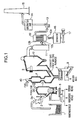
- FIG. 1 shows an example of a waste disposal plant provided with a fluidized-bed gasification-melting furnace.
- the present invention is widely applicable to operation of a gasification-melting furnace having a gasification furnace and a melting furnace.
- the overall configuration of the waste disposal plant adopting the gasification-melting furnace is not particularly limited.
- waste materials that is, items of refuse are once placed in a refuse pit 1 and thrown into a hopper 2a of a refuse feeder 2 which serves as a waste feeder by an unillustrated crane.
- the refuse feeder 2 feeds the refuse into a fluidized-bed gasification furnace 3 in prescribed quantities.
- This gasification furnace 3 performs a partial combustion process under conditions of an air ratio, for instance, of 0.2 to 0.4, that is, a pyrolysis process or primary combustion, with a fluidized bed including a layer of sand maintained at a temperature of 450°C to 650°C.
- Noncombustible material contained in the refuse thrown into the refuse feeder 2 is withdrawn from a furnace bottom and carried via a screw conveyer 5, a vibrating screen 6 and an unillustrated magnetic separator to be separated into noncombustible objects, nonferrous metals, ferrous metals and fluidized sand.
- the fluidized sand among them is returned to the layer of sand in the gasification furnace 3 for reuse.
- Pyrolysis gases produced in the gasification furnace 3 are led to a melting furnace 4 to be further combusted therein under conditions of an air ratio of 1.3, for instance.
- Performed in this melting furnace 4 is a high-temperature combustion process at about 1300°C with a spiral flow produced therein. This high-temperature combustion generates heat, which melts ash contained in the pyrolysis gases to separate the ash as slag from the pyrolysis gases while decomposing hazardous substances like dioxins contained in the gases.
- the molten slag is drawn out from the bottom of the melting furnace. 4, carried out by a slag removing unit 7 including a conveyer, cooled in a slag cooling unit 8 provided therebelow, and then collected.
- the exhaust gases discharged from the swirling-flow melting furnace 4 are led through an air heater 9 and a waste heat boiler 10, where heat within the pyrolysis gases is recovered.
- the exhaust gases after the heat-recovery are further cooled in a gas cooling unit 11 and dedusted by a bag filter 12.
- the exhaust gases thus cleaned are led by an induced draft fan 13 through a denitration unit 14 to be exausted through a chimney 15.
- FIG. 2 shows details of the structure of the gasification-melting furnace configured with the gasification furnace 3 and the melting furnace 4.
- a dispersion plate 20 having a large number of gas injection orifices 22 at a bottom of the gasification furnace 3, a wind box 24 formed below the dispersion plate 20. From the wind box 24 is ejected fluidization gas for example upward through the gas injection orifices 22 in the dispersion plate 20, thus forming a fluidized bed 26 of sand particles above the dispersion plate 20.
- the middle of the dispersion plate 20 is provided with a noncombustible material outlet 28, through which the noncombustible material is withdrawn to be led to the screw conveyer 5 and the vibrating screen 6.
- a refuse input port 30 connected to the refuse feeder 2.
- a dumper 32 for opening and closing off the path.
- a gasification furnace heat-up burner 34 At about the same height as the refuse input port 30 is provided a gasification furnace heat-up burner 34. Further above the gasification furnace heat-up burner 34 is formed a free board 36 for secondary combustion. At a furnace top is provided a pyrolysis gas output port 38.
- the pyrolysis gases discharged through the pyrolysis gas output port 38 are fed into an upper portion of the melting furnace 4.
- a burner 40 for auxiliary combustion At an appropriate location (a furnace top in the illustrated example) of the swirling-flow melting furnace 4, there is downwardly provided a burner 40 for auxiliary combustion.
- a pyrolysis gas input port 42 Immediately below this burner 40 is provided a pyrolysis gas input port 42, which is connected to the pyrolysis gas output port 38 of the gasification furnace 3 via a duct 44 serving as a pyrolysis gas channel.
- the burner 40 is used to raise and maintain the temperature of the melting furnace 4 (e.g. to maintain a state at a temperature of 1300°C or above). Operation of this burner 40 will be described later in detail.
- the melting furnace 4 is provided with a slag discharging port 43 at the bottom thereof, to which the slag removing unit 7 is connected.
- the duct 44 is provided with an oxygen analyser 45, which detects the concentration of oxygen contained in the gases fed from the gasification furnace 3 to the melting furnace 4.
- an oxygen analyser 45 which detects the concentration of oxygen contained in the gases fed from the gasification furnace 3 to the melting furnace 4.
- a thermometer 46 for detecting in-furnace temperature at the location (i.e., the temperature at the furnace top in this embodiment).
- the oxygen analyser 45 preferably has superior durability. Specifically, preferable is, for example, a zirconia-type oxygen analyzer.
- the thermometer 46 preferably has superb durability and excellent sensing accuracy in a high-temperature range. Specifically, a radiation pyrometer (especially an infrared radiation pyrometer) or the like is preferable. The location of this thermometer 46, though possibly determined as appropriate within a detectable range for the furnace-top temperature, is preferably determined so as to allow as stable a monitoring as possible to be made. For example, in case that a combustion air feeding nozzle 48 for the melting furnace shown in FIG. 3 is provided close to the pyrolysis gas input port 42 of the melting furnace 4, the thermometer 46 is preferably disposed at a position upstream from the nozzle 48, from which the thermometer 46 can monitor the inside of the top of the melting furnace 4 through the nozzle 48, as illustrated.
- a radiation pyrometer especially an infrared radiation pyrometer
- thermometer 46 This location of the thermometer 46 enables a combustion air flow from the nozzle 48 to the inside of the melting furnace 4a to be used for prevention of the ash or the like in the melting furnace 4 from clogging a detection window of the thermometer 46, thereby realizing a temperature monitoring in a stable manner.
- thermometer 46 may be chosen within a range close to the burner 40, specifically so near a range to the burner 40 that the ignition of the burner 40 can cause combustion of unburned gases.
- This gasification-melting furnace is further provided with a control system 50 shown in FIG. 2 , into which output signals (sensing signals) from the oxygen analyser 45 and the thermometer 46 are individually input.
- This control system 50 is configured with a computer and so on, functionally including a burner control section 52 and a refuse feeder control section 54.
- the burner control section 52 outputs command respective signals for making temporary shutdown and reignition of the burner 40.
- the refuse feeder control section 54 outputs respective command signals for making temporary shutdown and restart of the refuse feeder 2.
- a "normal operating state” (step S1) shown in FIG. 4 , the refuse feeder 2 is activated and the burner 40 of the melting furnace 4 has been ignited.
- the refuse feeder 2 feeds refuse like municipal solid wastes into the gasification furnace 3 through the refuse input port 30 of the furnace 3.
- the refuse is brought into a primary combustion in the fluidized bed 26 within the furnace 3, thereby producing pyrolysis gases.
- the pyrolysis gases are fed from the pyrolysis gas output port 38 at the furnace top to the pyrolysis gas input port 42 of the melting furnace 4 through the duct 44 and introduced into the upper portion of the furnace 4 through the input port 42.
- combustible constituents in the pyrolysis gases further combust at a high temperature, thus producing heat which melts ash contained in the gas into slag.
- This slag adheres to a furnace wall, and further flows down into the slag discharging port 43 at a furnace bottom to be withdrawn to the exterior of the furnace.
- the temperature at the top of the melting furnace 4 is held high by the burner 40 already ignited.
- the furnace top temperature already reached 1300°C spontaneous combustion of unburned components can keep the in-furnace temperature high for a while, even if operation of the auxiliary burner is stopped. Accordingly, from a viewpoint of fuel savings and environmental issues (especially in view of restrictions on CO 2 emissions), an appropriate rest of the burner operation is desirable.
- step S3 when a current operating state coincides with a preset burner stop condition (step S2), the control system 50 outputs a burner stop command signal (step S3) for stopping the operation of the burner 40.
- the burner stop conditions may be set in various ways.
- the condition may preferably include the following.
- the amount of heat possessed by the refuse may be approximately regarded as being equal to exhaust gas heat output Q calculated based on exhaust gas flow rate Fe (Nm 3 /h) detected by an exhaust gas flow meter provided at a location downstream from the bag filter 12 and exhaust gas temperature Te (°C) detected by an exhaust gas temperature sensor provided at a like location.
- exhaust gas heat output Q kcal/h
- a heat input by other media e.g., air, water and auxiliary fuel of the burner 40
- a heat output by these media in addition to the exhaust gas heat output Q, for calculation of the calorific value.
- the burner 40 may be caused to stop when at least one of 1) and 2) is satisfied or when both of 1) and 2) are satisfied.
- the burner stop command signal output in step S3 may be directly used as a control signal, or utilized as a notification signal for an operator.
- the burner stop command signal can realize automatic control of the burner 40, when input into an actuator of the burner 40.
- the burner stop command signal can be input into for instance an operating panel to light an indicator on the operating panel, thus notifying the operator of a proper burner stop timing to enable him to stop the operation of the burner 40, by manual intervention, at a proper timing.
- the burner 40 After thus stopping the operation of the burner 40, the burner 40 is reignitioned at a proper timing. If the burner 40 is reignited at a temperature equal to or lower than a spontaneous ignition temperature of the unburned gases after the furnace-top temperature has become equal to or lower than the spontaneous ignition temperature for one reason or another following the temporary shutdown of the burner 40, the reignition of the burner 40 may potentially induce an explosion depending on the concentration of the unburned gases.
- the control system 50 of this embodiment outputs the refuse charging stop command signal for stopping refuse charging operation of the refuse feeder 2 (step S5) at a point in time when the furnace-top temperature detected by the thermometer 46 drops down to a preset waste charging stop temperature (900°C in this embodiment) (Yes in step S4).
- the refuse charging stop command signal also may be directly input into, for example, a driving portion of the refuse feeder 2 to function as a signal for automatically stopping the refuse charging operation of the refuse feeder 2, or may be input into the operating panel and the like for lighting the indicator thereof to function as a signal for notifying the operator of a proper refuse charging stop timing.
- the refuse charging stop command signal may be output immediately upon the drop down of the furnace-top temperature to the waste charging stop temperature.
- the refuse charging stop command signal be output after a state where the furnace-top temperature is lowered to the waste charging stop temperature has been continued for a specific period of time (e.g., 2 to 20 seconds).
- the aforementioned stoppage of the refuse charging operation increases the concentration of oxygen contained in the gases fed from the gasification furnace 3 to the melting furnace 4 to make a safe state for the reignition of the burner 40 in the interior of the melting furnace 4.
- the control system 50 monitors the oxygen concentration in the gases detected by the oxygen analyser 45 and outputs a burner reignition command signal (step S8) at a point in time when the oxygen concentration has reached a preset burner reignition concentration ( 10% in this embodiment) (Yes in step S6).
- the control system 50 outputs the burner reignition command signal at a point in time when the furnace-top temperature reaches a specific temperature (950°C in this embodiment) higher than the burner reignition temperature due to an increase in the furnace-top temperature for one reason or another (Yes in step S7).
- this signal also may be directly input into the actuator of the burner 40 to automatically reignite the burner 40, or may be input into the operating panel to indicate a proper burner reignition timing to the operator.
- step S10 the control system 50 outputs a restart command signal to the refuse feeder 2 to restart it.
- This restarting step may also be performed manually by the operator.
- the above-described operation ensures a high degree of safety of restarting the burner 40 while intending fuel savings and suppression of CO 2 emissions by rest of the burner 40 at a proper timing.
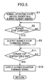
- FIG. 5 Another example of operation to ensure such a high degree of safety is shown in FIG. 5 .
- the operation control process shown in this Figure includes operation up to a point of outputting the burner reignition command signal (step S3) which is equal to what shown in FIG. 4 .
- the control system 50 outputs the burner reignition command signal (step S12) at a point in time when the furnace-top temperature has dropped down to a preset burner reignition temperature (1000°C in this embodiment) (Yes in step S11).
- the burner reignition temperature is set at so high a temperature as to reliably prevent abnormal combustion of the unburned gases due to reignition of the burner 40 at that temperature to thereby ensure a high degree of safety.
- a temperature at which safety has been assured by testing or the like is a temperature at which safety has been assured by testing or the like, the temperature being obtained by multiplying the spontaneous ignition temperature of the unburned gases (approximately 680°C in the case of natural gas, for example) by a sufficient safety factor.
- This kind of operation can also prevent excessive cooling of the interior of the melting furnace 4 in advance and assure a high degree of safety of burner reignition, by reigniting the burner 40 during the in-furnace temperature drops little after temporary shutdown of the burner 40.
- This operation may be performed in combination with the operation shown in FIG. 4 , that is, the operation of stopping the refuse charge to increase the oxygen concentration in the gases at the output port of the gasification furnace, for providing a fail-safe feature in case the burner 40 is not shut down even when the burner reignition command signal is output in step S12 or it becomes impossible to output this signal.
- the operation control process shown in FIG. 4 includes determining the burner reignition timing based on the oxygen concentration in the gas after stopping the refuse charging operation; however, as a parameter directly affecting the oxygen concentration may be monitored a cumulative value of the amount of air supplied to an side upstream from the melting furnace 4 after stoppage of the refuse charging operation, to determine the burner reignition timing based on this cumulative value. An example of this will be described with reference to FIGS. 6 and 7 .
- a facility shown in FIG. 6 is provided with a blower 60 and a flowmeter 62.
- the blower 60 is for supplying air to the gasification furnace 3, which air is supplied to the inside of the wind box 24 of the gasification furnace 3 as fluidization gas, and further delivered to the inside of the free board 36 as purging air in some cases.
- the pyrolysis gas output port 38 is provided at furnace top.
- the flowmeter 62 is provided on an outlet side of the blower 60 to detect the flow rate of air supplied from the blower 60 to the gasification furnace 3 and output a sensing signal concerning the detected flow rate. This sensing signal is input into the control system 50.
- FIG. 7 shows control operation of the control system 50.
- FIG. 7 shows operation up to a point,of outputting the refuse charging stop command signal (steps S1-S5) which is equal to the operation performed in the control process shown in FIG. 4 .
- the burner control section 52 After the output of the refuse charging stop command signal, the burner control section 52, from a point in time when the refuse charging operation is stopped, accumulates the amount of air supplied to the gasification furnace 3 based on the aforementioned sensing signal (step S6A), and outputs the burner reignition command signal (step S8) at a point in time when the cumulative value thus obtained reaches a preset fixed value (Yes in step S6B),.
- This control operation also enables the burner 40 to be reignited at a timing when the oxygen concentration in the vicinity of the burner 40 can be assumed to have increased to a certain extent as a result of air supply from the blower 60 after the temporary shutdown of the burner 40. This serves to assure a high degree of safety at the time of restarting the burner 40.
- the air subject to the aforementioned accumulating step includes either air which is so supplied to the side upstream from the melting furnace 4 as to contribute to an increased oxygen concentration inside the melting furnace 4.
- This air is therefore not limited to the air supplied to the inside of the gasification furnace 3.
- the purging air if supplied to the duct 44 provided between the gasification furnace 3 and the melting furnace 4, is also included in the air subject to the accumulating step.
- the present invention provides an operating method for operating a gasification-melting furnace provided with a gasification furnace for gasifying input waste material, a melting furnace configured to burn combustible constituents contained in pyrolysis gas produced in said gasification furnace and introduced in the melting furnace and melt ash in the pyrolysis gas, and a burner for auxiliary combustion provided in the melting furnace.
- This operating method comprises: stopping operation of the burner when an operating state of the gasification-melting furnace satisfies a specific burner stop condition; stopping charge of the waste material into the gasification furnace at a point in time when the temperature within the melting furnace in the vicinity of the burner drops down to a preset waste charging stop temperature after the operation of the burner has stopped; reigniting the burner at a point in time when oxygen concentration in the gas delivered from the gasification furnace to the melting furnace increases up to a preset burner reignition concentration after the charge of the waste material is stopped.
- the position where the "temperature within the melting furnace in the vicinity of the burner" is detected may be appropriately determined within a range where the burner reignition can cause a combustion of unburned gas.
- stopping charge of the waste material into the gasification furnace at a point in time when the temperature within the melting furnace in the vicinity of the burner drops down to a preset waste charging stop temperature includes not only stopping the charge of the waste material at the moment when the temperature within the gasification furnace has dropped the waste charging stop temperature, but also stopping the charge of the waste material after a state in which the furnace-top temperature remains lowered to the waste charging stop temperature has been continued for a preset period of time, to exclude a case of sudden drop of the furnace-top temperature.
- this operating method at a point in time when the temperature within the melting furnace in the vicinity of the burner drops down to the preset waste charging stop temperature (e.g., on the occurrence of a temperature state in which spontaneous combustion of the unburned gas has become difficult) after the burner is stopped operating, at first, stopping the charge of the waste material into the gasification furnace can increase the oxygen concentration in the gas delivered from the gasification furnace to the melting furnace, and thereafter, the burner reignition at a point in time when the oxygen concentration has increased up to the preset burner reignition concentration can ensure prevention of abnormal combustion of the unburned gas due to the reignition, thus ensuring successful combustion.
- the preset waste charging stop temperature e.g., on the occurrence of a temperature state in which spontaneous combustion of the unburned gas has become difficult
- the burner may be reignited regardless of the oxygen concentration.
- the waste charging stop temperature e.g., a temperature sufficiently high to prevent the abnormal combustion of the unburned gas
- the burner may be reignited at a point in time when the temperature within the melting furnace in the vicinity of the burner has dropped down to the preset waste charging stop temperature.
- This approach also can prevent reignition of the burner in an excessively low temperature range thereof (e.g., an temperature range in which spontaneous combustion of the unburned gas hardly occurs), thus assuring successful combustion.
- the burner stop condition may be set as appropriate. However, if this burner stop condition is such a condition that the temperature within the melting furnace in the vicinity of the burner or a moving average value thereof has been kept equal to or higher than a preset burner stop temperature for a specific period of time, means for detecting the aforementioned temperature can be used to take the waste charging stop timing or the burner reignition timing as well to make a judgment on the burner stop condition.
- the operation for reigniting the burner may be performed when the cumulative value of the amount of air supplied to the side upstream from the melting furnace from a point in time when the charging of the waste material is stopped reaches a fixed value. This performance allows a reignition while ensuring a sufficient oxygen concentration in a combustion range of the burner, thus assuring successful combustion.
- an operation control apparatus for performing the above-described operating method is an apparatus comprising: a waste feeder for charging the waste material into the gasification furnace; a thermometer for detecting the temperature within the melting furnace in the vicinity of the burner; an oxygen analyser for detecting oxygen concentration in the gas fed from the gasification furnace to the melting furnace; and a control system for controlling operation of the gasification furnace based on detection results of the thermometer and the oxygen analyser.
- the aforementioned control system includes a burner controller which outputs a burner stop command signal for stopping the operation of the burner when an operating state of the gasification-melting furnace satisfies a specific burner stop condition, and a waste charging controller which outputs a waste charging stop command signal for stopping the waste charge from charging the waste material into the gasification furnace at a point in time when the temperature detected by the thermometer drops down to a preset waste charging stop temperature after the burner has stopped operating.
- the burner controller outputs a burner reignition command signal for reigniting the burner at a point in time when the oxygen concentration detected by the oxygen analyser increases up to a preset burner reignition concentration after the waste feeder has stopped charging the waste material.
- the burner controller may output the burner reignition signal regardless of the oxygen concentration at a point in time when the temperature within the melting furnace in the vicinity of the burner detected by the thermometer increases up to a preset temperature higher than the waste charging stop temperature.
- Also provided as another operation control apparatus for performing the above-described operating method is an apparatus comprising: a waste feeder for charging waste material into a gasification furnace; a thermometer for detecting the temperature within a melting furnace in the vicinity of a burner; and a control system for controlling operation of the burner based on detection results of the thermometer; wherein the control system outputs a burner stop signal for stopping the operation of the burner when an operating state of the gasification-melting furnace satisfies a specific burner stop condition as well as a burner reignition signal for restarting the operation of the burner at a point in time when the temperature detected by the thermometer drops down to a preset burner reignition concentration after the burner has stopped operating.
- the burner stop condition of the above-described apparatus includes that the temperature detected by the thermometer or a moving average value thereof has been kept equal to or higher than a preset burner stop temperature for a specific period of time.
- Also provided as another operation control apparatus for performing the above-described operating method is an apparatus comprising: a burner controller which outputs a burner stop signal for stopping operation of a burner when an operating state of a gasification-melting furnace satisfies a specific burner stop condition; and a waste charging controller which outputs a waste charging stop command signal for stopping a waste feeder from charging the waste material into a gasification furnace at a point in time when the temperature detected by a thermometer drops down to a preset waste charging stop temperature after the burner has stopped operating, wherein the burner controller accumulates the amount of air detected by an air quantity detector from a point in time when the waste feeder has stopped charging the waste material and outputs a burner reignition signal for restarting the operation of the burner at a point in time when a cumulative value thus obtained reaches a preset fixed value.
- Each of the above-described operation control apparatuses can configure an excellent gasification-melting furnace in combination with a gasification furnace for gasifying input waste material, a waste feeder for charging the waste material into the gasification furnace, a melting furnace configured to burn combustible constituents contained in pyrolysis gas produced in said gasification furnace and introduced in the melting furnace and melt ash in the pyrolysis gas, and a burner for combustion provided in the melting furnace.
- FIG. 8 shows the overall configuration of a waste disposal plant including a gasification-melting furnace to which the present second invention is applied.
- This plant is provided with a gasification-melting furnace 110, a refuse feeding section 112 for feeding waste materials, that is, items of refuse to the gasification-melting furnace 110 and a gas treatment section 114 for treating gases discharged from the gasification-melting furnace 110.
- the refuse feeding section 112 is equipped with a refuse pit 116, a refuse mover 118 and a refuse feeder 120.
- the refuse pit 116 receives and once stores the items of refuse to be treated that are carried in from outside the plant.
- the refuse mover 118 provided with a crane, grasps the refuse in the refuse pit 116 and moves the same to the refuse feeder 120.
- the refuse feeder 120 has a hopper 122, which receives the refuse fed from the refuse mover 118.
- the amount of charged refuse corresponds to a refuse charging quantity fed into the gasification-melting furnace 110.
- the refuse feeder 120 incorporating a screw conveyer, supplies the refuse thrown into the hopper 122 to the gasification-melting furnace 110.
- the gasification-melting furnace 110 has a gasification furnace 124 and a melting furnace 126.
- the gasification furnace 124 performs pyrolytisis of the refuse charged from the refuse feeder 120, thereby producing pyrolysis gases.
- As the gasification furnace 124 can be employed, for example, a known fluidized-bed furnace or kiln.
- the melting furnace 126 combusts combustible constituents in the pyrolysis gases at a high temperature to melt ash contained in the gases into slag.
- the slag adheres to a furnace wall of the melting furnace 126, for instance.
- the melting furnace 126 is provided with a slag discharging port 128 at a furnace bottom.
- the slag discharging port 128 is for discharging the slag that adheres to the furnace wall and flows down therefrom to the exterior of the furnace.
- combustion of auxiliary fuel by an unillustrated burner for adjusting in-furnace temperature is performed as required.
- the gas treatment section 114 is provided with a waste heat boiler 130, a cooling chamber 132, a dust collector 134, an induced draft fan 136 and a chimney 138.
- the waste heat boiler 130 is for recovering heat from high-temperature exhaust gas discharged from the melting furnace 126, specifically for producing steam by using the heat possessed by the exhaust gas and discharging the steam.
- the flow rate of the discharged steam i.e., the amount of steam produced in the waste heat boiler 130 per unit time, serves as a parameter corresponding to the calorific value of the refuse charged into the gasification-melting furnace 110 per unit time.
- the cooling chamber 132 is equipped with a tower structure into which gas discharged from the waste heat boiler 130 is introduced, a sprayer for spraying cooling water into the tower structure, a temperature sensor for detecting gas temperature at an outlet of the tower structure and a controller for regulating the flow rate of the cooling water supplied by the sprayer so as to make the outlet gas temperature detected by the temperature sensor keep constant.
- the dust collector 134 captures dust or the like contained in the gas discharged from the cooling chamber 132.
- the dust-removed gas from the dust collector 134 is discharged through the chimney 138 via the induced draft fan 136.
- This plant further includes a basicity adjusting unit 140.
- the basicity adjusting unit 140 for adjusting the basicity of the slag discharged through the slag discharging port 128 of the melting furnace 126, comprises a basicity adjuster feeder 142, a steam flowmeter 144, a refuse charging . quantity output portion 146 and a controller 150.
- the basicity adjuster feeder 142 for supplying a basicity adjuster into the refuse charged into the gasification furnace 124, comprises a screw conveyer 147 which serves as transport means for supplying the basicity adjuster and a motor 148 for turning the screw conveyer 147.
- the basicity adjuster is appropriately selected. This embodiment is intended only to excessively high basicity of the discharged slag, so that quartz sand (SiO 2 ) for decreasing the basicity of the slag is selected as the basicity adjuster.
- the steam flowmeter 144 measures the flow rate of the discharged steam, that is, the amount of steam produced in the waste heat boiler 130 per unit time.
- the refuse charging quantity output portion 146 outputs an information signal concerning the weight of the refuse charged into the gasification furnace 124 per unit time. Specifically, the refuse charging quantity output portion 146 is additionally provided to the refuse mover 118 to calculate the amount of refuse convey based on the weight load applied to the refuse mover 118 and the number of moving operations, and to provide it to the controller 150 as information regarding the amount of refuse charge into the gasification-melting furnace 110.
- the controller 150 configured with a microcomputer and so on, has a function of totally controlling the entirety of the plant, including an expected basicity value calculator 152 and a basicity adjuster quantity regulator 154 to serve a function of adjusting the basicity of the slag.
- the expected basicity value calculator 152 calculates a predicted value of the basicity of the slag discharged from the slag discharging port 128, based on the information signal concerning the weight of the refuse charged into the gasification furnace 124 per unit time and the flow rate of the steam measured by the steam flowmeter 144. Calculation of this expected value is accomplished by a step of calculating the calorific value of refuse per unit weight based on the amount of refuse charged per unit time and the flow rate of the discharged steam and a step of calculating the predicted value of the basicity based on the calorific value of refuse per unit weight.
- the correlation can be predetermined by actual measurements. Specifically, measuring the actual slag basicity corresponding to the flow rate of the steam by an analyzer for a particular period of time enables the correlation to be estimated, as shown in later-discussed Examples.
- the correlation can be approximately expressed for example in a first-degree equation (a linear equation).
- the expected basicity value calculator 152 stores the correlation and calculates the expected value of the basicity based on the correlation and the flow rate of the steam actually measured by the steam flowmeter 144.
- a value of the flow rate of the discharged steam on which the calculation of the expected value of the basicity is based is an average value of values by the steam flowmeter 144 during a specific period of time. This period of time can be set as appropriate, preferably at about 6 to 24 hours in general terms.
- the basicity adjuster quantity regulator 154 determines the amount of the basicity adjuster supply for making the basicity approach a preset target value (e.g., 0.5), based on the expected value of the slag basicity calculated by the expected basicity value calculator 152 and the information signal concerning the weight of the charged refuse input from the refuse charging quantity output portion 146. Then, to obtain the determined amount of supply, the basicity adjuster quantity regulator 154 outputs a control signal to the motor 148 of the basicity adjuster feeder 142 to control the rotation speed thereof. In advance can be prepared a relationship between the expected value and the actual amount of the basicity adjuster supply, based on theory or simulation.
- a preset target value e.g., 0.5
- the expected value of the basicity is calculated based on detected values of that parameter and the relationship.
- This method can be carried out even within a plant not including the aforementioned waste heat boiler 130.
- a parameter concerning the calorific value of the refuse can be selected, for example, a flow rate of the cooling water supply in the cooling chamber 132. Since this cooling chamber 132, as previously described, is provided with the temperature sensor for detecting gas temperature at the outlet of the tower structure and the controller for regulating the flow rate of the cooling water supply by the sprayer so as to keep constant the outlet gas temperature detected by the temperature sensor, the flow rate of the cooling water supply corresponds to the calorific value of the refuse charged into the gasification-melting furnace 110 per unit time.
- a feeding position of the basicity adjuster is not limited to an inlet side of the gasification furnace 124, permitted to be appropriately determined in a range upstream from the slag discharging port 128.
- the position may be determined within a range between the gasification furnace 124 and the melting furnace 126 or inside a combustion chamber of the melting furnace 126 upstream from the slag discharging port 128 thereof.
- FIG. 9 shows annual changes in the calorific value of refuse per unit weight (kcal/kg) and basicity of slag in a certain waste disposal plant. This Figure clearly indicates that the calorific value of the refuse and the basicity vary similarly to each other.
- FIG. 10 is a graphical representation of respective relationships between the calorific value of refuse and basicity of slag determined by actual measurements in two waste disposal plants (plant A and plant B). As shown in this Figure, either of plants A and B has a specific relationship between the calorific value of refuse and basicity of slag. The two plants A and B are so different from each other in components of the refuse charged into the gasification-melting furnaces thereof that the respective relationships between the calorific value of refuse and the basicity of slag in the plants A and B differ from each other, while both of the relationships can be approximately assumed to be first-degree functions.
- each relationship when input and stored into the expected basicity value calculator 152 in advance, enables the calculator 152 to quickly calculate an expected value of the slag basicity based on the parameter corresponding to the calorific value of the refuse (e.g., flow rate of the steam discharged from the waste heat boiler 30).
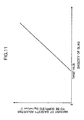
- the relationship between the expected value of the slag basicity and the amount of the basicity adjuster supply in advance based on theory or simulation. For example, under the assumption of only down adjustment of the slag basicity, a relationship between the amount of the basicity adjuster (e.g., quartz sand) to be supplied (the amount of supply corresponding to the amount of refuse charged per unit time) and the expected value of the basicity is preferably set as shown in FIG. 11 . According to this setting, when the expected value of the basicity exceeds a target value (e.g., 0.5), the basicity adjuster is supplied in a quantity corresponding to an excess amount of the expected value.
- a target value e.g., 0.5
- this embodiment provides a method of adjusting basicity of slag in operating a gasification-melting furnace which brings charged waste material into pyrolysis and melts ash in pyrolysis gas produced by the pyrolysis, the gasification-melting furnace having a slag discharging port for discharging the slag produced by melting the ash.
- the basicity adjusting method comprising: a step of supplying a basicity adjuster for adjusting the basicity of the slag discharged through the slag discharging port at a position upstream therefrom; a step of detecting the weight of the waste material charged into the gasification-melting furnace per unit time; a step of detecting a parameter corresponding to the calorific value of the waste material per unit weight; a step of calculating an expected value of the basicity of the slag produced inside the gasification-melting furnace based on a detected value of the parameter, and a step of regulating the amount of the basicity adjuster supply toward a preset target value of the basicity, based on the calculated expected value of the basicity.
- this basicity adjusting method utilizing a correlation between the parameter corresponding to the calorific value of the waste material per unit weight and the actual slag basicity allows the expected value of the actual slag basicity to be obtained without a complicated analysis of the slag composition.
- the expected value of the basicity can be calculated based on the detected value of the parameter and the correlation. Based on the expected value of the slag basicity, a proper amount of the basicity adjuster addition is determined.
- the calorific value of the waste material per unit weight is effectively detected an amount of steam produced in a waste heat boiler per unit time by use of heat of gas discharged from the gasification-melting furnace.
- the amount of steam production is easily detected.
- the calorific value of the waste material per unit weight can be properly calculated.
- a method for calculating the expected value of the basicity for example, effective is a method including a step of determining a relationship between the parameter and the actual slag basicity by actual measurement, in advance of the step of calculating the expected value of the basicity of the slag produced in the gasification-melting furnace, wherein the expected value of the basicity of the slag produced in the gasification-melting furnace is calculated based on the relationship and the detected value of the parameter.
- a proper expected value of the basicity of the slag is quickly calculated based on the relationship between the predetermined parameter and the actual slag basicity.
- a basicity adjusting apparatus of a gasification-melting furnace for performing the above-described basicity adjusting method.
- This apparatus comprises: a basicity adjuster feeder for supplying a basicity adjuster for adjusting basicity of slag discharged through a slag discharging port at a position upstream therefrom; a waste material charging quantity detector for detecting the weight of waste material charged into the gasification-melting furnace per unit time; a parameter detector for detecting a parameter corresponding to the calorific value of the waste material per unit weight; an expected basicity value calculator for calculating an expected value of the basicity of the slag produced inside the gasification-melting furnace based on a detected value of the parameter; and a basicity adjuster quantity regulator for regulating the amount of the basicity adjuster supply so as to make the slag basicity approach a preset target value of the basicity, based on the expected value of the basicity.
- the parameter detector of this apparatus for example, preferably detects the amount of steam produced in a waste heat boiler per unit time by use of heat of gas discharged from the gasification-melting furnace.
- the expected basicity value calculator can calculate the calorific value of the waste material per unit weight based on the parameter detected by the parameter detector and the amount of the waste material charged into the gasification-melting furnace per unit time.
- the basicity adjuster quantity regulator for example, preferably stores a relationship between the parameter determined by actual measurement and the actual basicity of the slag, and determines the amount of the basicity adjuster supply based on the relationship thus stored and the detected value of the parameter.
Claims (6)
- Betriebsverfahren für einen Gasifizierungs-Schmelzofen (3, 4) zum Betreiben des Gasifizierungs-Schmelzofens (3,4), versehen mit einem Gasifizierungsofen (3) zum Gasifizieren von Eingangsabfallmaterial, einem Schmelzofen (4), gestaltet um verbrennbare Bestandteile, enthalten in Pyrolysegas, erzeugt in dem Gasifizierungsofen (3) und eingeführt in den Schmelzofen (4), und Schmelzasche in dem Pyrolysegas zu verbrennen, und einem Brenner (40) zur hilfsweisen Verbrennung, bereitgestellt in dem Schmelzofen (4), wobei das Betriebsverfahren umfaßt:das Betreiben des Stoppens des Betriebs des Brenners (40), wenn ein Betriebszustand des Gasifizierungs-Schmelzofens (3,4) einer spezifischen Brennerstopbedingung genügt,das Betreiben des Stoppens von Zufuhr des Abfallmaterials in den Gasifizierungsofen (3) an einem Zeitpunkt, wenn die Temperatur innerhalb des Schmelzofens (4) in der Nachbarschaft des Brenners (40) auf eine voreingestellte Abfallzufuhr-Stoptemperatur fällt, nachdem der Brenner (40) den Betrieb gestoppt hat, unddas Wiederanzünden des Brenners (40) an einem Zeitpunkt, wenn die Sauerstoffkonzentration in dem Gas, beschickt von dem Gasifizierungsofen (3) zu dem Schmelzofen (4), auf eine voreingestellte Brennerwiederanzündungskonzentration ansteigt, nachdem das Beschicken des Abfallmaterials gestoppt worden ist.
- Betriebsverfahren für den Gasifizierungs-Schmelzofen, wie in Anspruch 1 ausgeführt, wobei der Brenner (40) wieder angezündet wird, unabhängig von der Sauerstoffkonzentration, an dem Zeitpunkt, wenn die Temperatur innerhalb des Schmelzofens (4) in der Nachbarschaft des Brenners (40) auf eine eingestellte Temperatur höher als die Abfallzufuhr-Stoptemperatur ansteigt, nachdem der Brenner (40) gestoppt worden ist, betrieben zu werden.
- Betriebsverfahren für den Gasifizierungs-Schmelzofen (3, 4), wie in Anspruch 1 oder 2 ausgeführt, wobei die Brennerstopbedingung einschließt, dass ein Zustand, bei welchem die Temperatur innerhalb des Schmelzofens (4) in der Nachbarschaft des Brenners (40) oder ein sich bewegender Durchschnittswert davon gleich oder höher ist, als eine voreingestellte Brennerstoptemperatur für eine spezifische Zeitdauer beibehalten wird.
- Betriebskontrollvorrichtung für einen Gasifizierungs-Schmelzofen (3,4) zum Kontrollieren des Betriebs des Gasifizierungs-Schmelzofens (3,4), versehen mit einem Gasifizierungsofen (3) zum Gasifizieren von Einlaßabfallmaterial, einem Schmelzofen (4), gestaltet um verbrennbare Bestandteile, enthalten in Pyrolysegas, erzeugt in dem Gasifizierungsofen (3) und eingeführt in den Schmelzofen (4), und geschmolzene Asche in dem Pyrolysegas zu verbrennen, und einem Brenner (40) zum hilfsweisen Verbrennen, angeordnet in dem Schmelzofen (4), wobei die Betriebskontrollvorrichtung umfaßt:eine Abfallbeschickungsvorrichtung (2) zum Beschicken des Abfallmaterials in den Gasifizierungsofen (3), ein Thermometer (46) zum Detektieren der Temperatur innerhalb des Schmelzofens (4) in der Nachbarschaft des Brenners (40),wobei die Betriebskontrollvorrichtung gekennzeichnet ist, dadurch, daß:die Kontrollvorrichtung umfaßt: einen Sauerstoffanalysator (45) zum Detektieren der Sauerstoffkonzentration in dem Gas, beschickt von dem Gasifizierungsofen (3) zu dem Schmelzofen (4), und ein Kontrollsystem (50) zum Kontrollieren des Betriebs des Gasifizierungsofens (3), basierend auf Detektionsresultaten des Thermometers (46) und des Sauerstoffanalysators (45), wobei das Kontrollsystem (50) einschließt: eine Brennerkontrollvorrichtung (52), welche ein Brennerstop-Anordnungssignal zum Stoppen des Betriebs des Brenners (40) ausgibt, wenn ein Betriebszustand des Gasifizierungs-Schmelzofens (3, 4) einer spezifischen Brennerstopbedingung genügt,eine Abfallzuführkontrollvorrichtung (54), welche ein Abfallzufuhr-Stopanordnungssignal zum Stoppen der Abfallzufuhr zum Zuführen des Abfallmaterials in den Gasifizierungsofen (3) zu einem Zeitpunkt, wenn die Temperatur, detektiert durch das Thermometer, auf eine vorbestimmte Abfallzufuhr-Stoptemperatur fällt, nachdem der Brenner (40) gestoppt worden ist, betrieben zu werden, ausgibt, unddie Brennerkontrollvorrichtung (52) ein Brennerwiederanzündungsanordnungssignal zum Wiederanzünden des Brenners (40) zu einem Zeitpunkt, wenn die Sauerstoffkonzentration, detektiert durch den Sauerstoffanalysator (45), auf eine vorbestimmte Brennerwiederanzündungskonzentration ansteigt, nachdem die Abfallbeschickungsvorrichtung (2) gestoppt worden ist, das Abfallmaterial zuzuführen, ausgibt.
- Betriebskontrollvorrichtung des Gasifizierungs-Schmelzofens (3, 4), wie in Anspruch 4 ausgeführt, wobei die Brennerkontrollvorrichtung (52) das Brennerwiederanzündungssignal ausgibt, unabhängig von der Sauerstoffkonzentration, zu dem Zeitpunkt, wenn die Temperatur, detektiert durch das Thermometer (46), auf eine vorbestimmte Temperatur höher als die Abfallzufuhr-Stoptemperatur ansteigt, nachdem der Brenner (40) gestoppt worden ist, betrieben zu werden, ausgibt.
- Betriebskontrollvorrichtung für den Gasifizierungs-Schmelzofen (3, 4), wie in Anspruch 4 oder 5 ausgeführt, wobei die Brennerstopbedingung einschließt, daß die Temperatur, detektiert durch das Thermometer (46), oder ein sich bewegender Durchschnittswert davon gleich oder höher als eine vorbestimmte Brennerstoptemperatur für eine spezifische Zeitdauer beibehalten wird.
Priority Applications (2)
| Application Number | Priority Date | Filing Date | Title |
|---|---|---|---|
| PL07806476T PL2068081T3 (pl) | 2006-09-26 | 2007-08-31 | Sposób działania i urządzenie do kontroli pracy pieca do zgazowania |
| EP11001719.1A EP2322855B1 (de) | 2006-09-26 | 2007-08-31 | Betriebsverfahren und Steuervorrichtung für Vergasungsschmelzofen |
Applications Claiming Priority (4)
| Application Number | Priority Date | Filing Date | Title |
|---|---|---|---|
| JP2006260083 | 2006-09-26 | ||
| JP2007050892A JP2008215665A (ja) | 2007-03-01 | 2007-03-01 | ガス化溶融炉におけるスラグの塩基度の調整方法及び装置 |
| JP2007141664A JP4966743B2 (ja) | 2006-09-26 | 2007-05-29 | ガス化溶融炉の運転方法及び運転制御装置 |
| PCT/JP2007/067003 WO2008038492A1 (fr) | 2006-09-26 | 2007-08-31 | PROCÉDÉ DE FONCTIONNEMENT ET APPAREIL DE COMMANDE DE FONCTIONNEMENT POUR UN FOUR à FUSION DE GAZÉIFICATION |
Related Child Applications (2)
| Application Number | Title | Priority Date | Filing Date |
|---|---|---|---|
| EP11001719.1A Division EP2322855B1 (de) | 2006-09-26 | 2007-08-31 | Betriebsverfahren und Steuervorrichtung für Vergasungsschmelzofen |
| EP11001719.1A Division-Into EP2322855B1 (de) | 2006-09-26 | 2007-08-31 | Betriebsverfahren und Steuervorrichtung für Vergasungsschmelzofen |
Publications (3)
| Publication Number | Publication Date |
|---|---|
| EP2068081A1 EP2068081A1 (de) | 2009-06-10 |
| EP2068081A4 EP2068081A4 (de) | 2011-05-11 |
| EP2068081B1 true EP2068081B1 (de) | 2014-04-16 |
Family
ID=39229931
Family Applications (2)
| Application Number | Title | Priority Date | Filing Date |
|---|---|---|---|
| EP07806476.3A Active EP2068081B1 (de) | 2006-09-26 | 2007-08-31 | Betriebsverfahren und betriebssteuervorrichtung für vergasungsschmelzofen |
| EP11001719.1A Active EP2322855B1 (de) | 2006-09-26 | 2007-08-31 | Betriebsverfahren und Steuervorrichtung für Vergasungsschmelzofen |
Family Applications After (1)
| Application Number | Title | Priority Date | Filing Date |
|---|---|---|---|
| EP11001719.1A Active EP2322855B1 (de) | 2006-09-26 | 2007-08-31 | Betriebsverfahren und Steuervorrichtung für Vergasungsschmelzofen |
Country Status (5)
| Country | Link |
|---|---|
| EP (2) | EP2068081B1 (de) |
| KR (1) | KR101107787B1 (de) |
| ES (1) | ES2461769T3 (de) |
| PL (2) | PL2068081T3 (de) |
| WO (1) | WO2008038492A1 (de) |
Families Citing this family (6)
| Publication number | Priority date | Publication date | Assignee | Title |
|---|---|---|---|---|
| US8940062B2 (en) * | 2009-10-28 | 2015-01-27 | Ihi Corporation | Method and apparatus for controlling temperature in combustion furnace in gasification equipment |
| JP5425983B2 (ja) * | 2012-08-02 | 2014-02-26 | 株式会社神鋼環境ソリューション | ガス化溶融炉のガス温度制御方法、及びガス温度制御装置 |
| FR3009977B1 (fr) * | 2013-09-02 | 2018-07-06 | Savoie Dechets | Procede de vitrification par gazeification d'une matiere carbonee |
| JP5826954B1 (ja) * | 2015-01-19 | 2015-12-02 | 株式会社神鋼環境ソリューション | 廃棄物処理システム及びそのシステムにおけるNOx処理方法 |
| CN108954364A (zh) * | 2018-05-19 | 2018-12-07 | 潘礼斌 | 一种粪便气化清洁供热系统 |
| CN110094725B (zh) * | 2019-05-10 | 2020-04-28 | 东北电力大学 | 一种燃煤发电机组超低氮燃烧方法 |
Family Cites Families (10)
| Publication number | Priority date | Publication date | Assignee | Title |
|---|---|---|---|---|
| US4013023A (en) * | 1975-12-29 | 1977-03-22 | Envirotech Corporation | Incineration method and system |
| JPH06159640A (ja) * | 1992-11-26 | 1994-06-07 | Ebara Infilco Co Ltd | 塩基度調整装置及びその調整方法 |
| JP2001182924A (ja) | 1999-12-28 | 2001-07-06 | Nkk Corp | 溶融炉の運転方法 |
| KR100763531B1 (ko) * | 2000-08-11 | 2007-10-05 | 가부시키가이샤 긴세이 산교 | 폐기물의 소각처리방법 |
| JP2003302023A (ja) * | 2002-04-10 | 2003-10-24 | Ebara Corp | 溶融炉の運転方法、運転制御装置及びガス化溶融システム |
| JP4009151B2 (ja) | 2002-07-08 | 2007-11-14 | 株式会社神鋼環境ソリューション | ガス化溶融炉の燃焼制御方法及びその装置 |
| US20040137390A1 (en) * | 2003-01-09 | 2004-07-15 | Arnold Kenny M. | Methods and systems for measuring and controlling the percent stoichiometric oxidant in an incinerator |
| JP2004353944A (ja) * | 2003-05-29 | 2004-12-16 | Hitachi Zosen Corp | ごみ処理設備等における燃焼制御方法およびごみ処理設備 |
| JP4154371B2 (ja) | 2004-07-15 | 2008-09-24 | 株式会社神鋼環境ソリューション | 流動床式ガス化溶融炉の廃棄物供給停止時における保温方法 |
| JP4361890B2 (ja) * | 2005-06-14 | 2009-11-11 | 株式会社神鋼環境ソリューション | ガス化溶融炉のスラグ塩基度調整方法及びその装置 |
-
2007
- 2007-08-31 PL PL07806476T patent/PL2068081T3/pl unknown
- 2007-08-31 PL PL11001719.1T patent/PL2322855T3/pl unknown
- 2007-08-31 ES ES07806476.3T patent/ES2461769T3/es active Active
- 2007-08-31 EP EP07806476.3A patent/EP2068081B1/de active Active
- 2007-08-31 EP EP11001719.1A patent/EP2322855B1/de active Active
- 2007-08-31 WO PCT/JP2007/067003 patent/WO2008038492A1/ja active Application Filing
- 2007-08-31 KR KR1020097007726A patent/KR101107787B1/ko active IP Right Grant
Also Published As
| Publication number | Publication date |
|---|---|
| WO2008038492A1 (fr) | 2008-04-03 |
| EP2068081A4 (de) | 2011-05-11 |
| EP2322855B1 (de) | 2016-04-13 |
| PL2322855T3 (pl) | 2016-09-30 |
| EP2068081A1 (de) | 2009-06-10 |
| ES2461769T3 (es) | 2014-05-21 |
| PL2068081T3 (pl) | 2014-09-30 |
| KR20090057441A (ko) | 2009-06-05 |
| EP2322855A3 (de) | 2011-08-31 |
| KR101107787B1 (ko) | 2012-01-20 |
| EP2322855A2 (de) | 2011-05-18 |
Similar Documents
| Publication | Publication Date | Title |
|---|---|---|
| EP2068081B1 (de) | Betriebsverfahren und betriebssteuervorrichtung für vergasungsschmelzofen | |
| KR100852507B1 (ko) | 폐기물 용융로의 가연성 가스의 처리 방법 및 처리 장치 | |
| TWI526664B (zh) | 加熱金屬的方法和設備 | |
| EP1148295B1 (de) | Abfallvergasungsschmelzofen und vergasungsschmelzverfahren | |
| JP4833270B2 (ja) | ガス化溶融炉の運転制御装置 | |
| JP5154094B2 (ja) | ガス化溶融システムの燃焼制御方法及び該システム | |
| JP5611418B2 (ja) | ガス化溶融システムの燃焼制御方法及び該システム | |
| JP3963925B2 (ja) | 焼却処理システムにおける二次燃焼方法及び装置 | |
| JP5222502B2 (ja) | ロータリーキルンの運転方法 | |
| SK283426B6 (sk) | Spôsob riadeného spaľovania | |
| JP4234727B2 (ja) | 溶融炉の炉内状況監視・制御方法及び該装置 | |
| JP3944389B2 (ja) | 熱分解ガス化溶融炉における燃焼空気量制御システム | |
| JP4096509B2 (ja) | ガス化溶融装置及び方法 | |
| JP4918834B2 (ja) | 廃棄物溶融炉および廃棄物溶融炉の操業方法 | |
| JP3902454B2 (ja) | 燃焼制御方法及び廃棄物処理装置 | |
| JP4966743B2 (ja) | ガス化溶融炉の運転方法及び運転制御装置 | |
| JP2003287213A (ja) | ごみ焼却炉の燃焼制御装置 | |
| JP3556078B2 (ja) | ゴミ焼却炉の給塵速度制御方法及びゴミ焼却炉 | |
| JPH11351558A (ja) | 燃焼炉の燃焼制御方法及び燃焼制御装置 | |
| JPH11351538A (ja) | 溶融炉の燃焼制御方法及び装置 | |
| JP2008215665A (ja) | ガス化溶融炉におけるスラグの塩基度の調整方法及び装置 | |
| JPH0125964B2 (de) | ||
| TINABURRI et al. | RDF Fluidised Bed Combustor Safety Issues | |
| JP2001248820A (ja) | 廃棄物溶融処理装置および廃棄物溶融処理方法 |
Legal Events
| Date | Code | Title | Description |
|---|---|---|---|
| PUAI | Public reference made under article 153(3) epc to a published international application that has entered the european phase |
Free format text: ORIGINAL CODE: 0009012 |
|
| 17P | Request for examination filed |
Effective date: 20090326 |
|
| AK | Designated contracting states |
Kind code of ref document: A1 Designated state(s): AT BE BG CH CY CZ DE DK EE ES FI FR GB GR HU IE IS IT LI LT LU LV MC MT NL PL PT RO SE SI SK TR |
|
| AX | Request for extension of the european patent |
Extension state: AL BA HR MK RS |
|
| A4 | Supplementary search report drawn up and despatched |
Effective date: 20110407 |
|
| DAX | Request for extension of the european patent (deleted) | ||
| GRAP | Despatch of communication of intention to grant a patent |
Free format text: ORIGINAL CODE: EPIDOSNIGR1 |
|
| INTG | Intention to grant announced |
Effective date: 20131120 |
|
| GRAS | Grant fee paid |
Free format text: ORIGINAL CODE: EPIDOSNIGR3 |
|
| GRAA | (expected) grant |
Free format text: ORIGINAL CODE: 0009210 |
|
| AK | Designated contracting states |
Kind code of ref document: B1 Designated state(s): AT BE BG CH CY CZ DE DK EE ES FI FR GB GR HU IE IS IT LI LT LU LV MC MT NL PL PT RO SE SI SK TR |
|
| REG | Reference to a national code |
Ref country code: GB Ref legal event code: FG4D |
|
| RIN1 | Information on inventor provided before grant (corrected) |
Inventor name: HOSODA, HIROYUKI Inventor name: MINAKAWA, KOJI Inventor name: NIKAIDO, HIROO Inventor name: ITO, TADASHI |
|
| REG | Reference to a national code |
Ref country code: CH Ref legal event code: EP |
|
| REG | Reference to a national code |
Ref country code: AT Ref legal event code: REF Ref document number: 662805 Country of ref document: AT Kind code of ref document: T Effective date: 20140515 |
|
| REG | Reference to a national code |
Ref country code: ES Ref legal event code: FG2A Ref document number: 2461769 Country of ref document: ES Kind code of ref document: T3 Effective date: 20140521 Ref country code: IE Ref legal event code: FG4D |
|
| REG | Reference to a national code |
Ref country code: DE Ref legal event code: R096 Ref document number: 602007036147 Country of ref document: DE Effective date: 20140528 |
|
| REG | Reference to a national code |
Ref country code: AT Ref legal event code: MK05 Ref document number: 662805 Country of ref document: AT Kind code of ref document: T Effective date: 20140416 |
|
| REG | Reference to a national code |
Ref country code: NL Ref legal event code: VDEP Effective date: 20140416 |
|
| REG | Reference to a national code |
Ref country code: LT Ref legal event code: MG4D |
|
| REG | Reference to a national code |
Ref country code: PL Ref legal event code: T3 |
|
| PG25 | Lapsed in a contracting state [announced via postgrant information from national office to epo] |
Ref country code: BG Free format text: LAPSE BECAUSE OF FAILURE TO SUBMIT A TRANSLATION OF THE DESCRIPTION OR TO PAY THE FEE WITHIN THE PRESCRIBED TIME-LIMIT Effective date: 20140716 Ref country code: LT Free format text: LAPSE BECAUSE OF FAILURE TO SUBMIT A TRANSLATION OF THE DESCRIPTION OR TO PAY THE FEE WITHIN THE PRESCRIBED TIME-LIMIT Effective date: 20140416 Ref country code: GR Free format text: LAPSE BECAUSE OF FAILURE TO SUBMIT A TRANSLATION OF THE DESCRIPTION OR TO PAY THE FEE WITHIN THE PRESCRIBED TIME-LIMIT Effective date: 20140717 Ref country code: IS Free format text: LAPSE BECAUSE OF FAILURE TO SUBMIT A TRANSLATION OF THE DESCRIPTION OR TO PAY THE FEE WITHIN THE PRESCRIBED TIME-LIMIT Effective date: 20140816 Ref country code: CY Free format text: LAPSE BECAUSE OF FAILURE TO SUBMIT A TRANSLATION OF THE DESCRIPTION OR TO PAY THE FEE WITHIN THE PRESCRIBED TIME-LIMIT Effective date: 20140416 Ref country code: FI Free format text: LAPSE BECAUSE OF FAILURE TO SUBMIT A TRANSLATION OF THE DESCRIPTION OR TO PAY THE FEE WITHIN THE PRESCRIBED TIME-LIMIT Effective date: 20140416 Ref country code: NL Free format text: LAPSE BECAUSE OF FAILURE TO SUBMIT A TRANSLATION OF THE DESCRIPTION OR TO PAY THE FEE WITHIN THE PRESCRIBED TIME-LIMIT Effective date: 20140416 |
|
| PG25 | Lapsed in a contracting state [announced via postgrant information from national office to epo] |
Ref country code: SE Free format text: LAPSE BECAUSE OF FAILURE TO SUBMIT A TRANSLATION OF THE DESCRIPTION OR TO PAY THE FEE WITHIN THE PRESCRIBED TIME-LIMIT Effective date: 20140416 Ref country code: AT Free format text: LAPSE BECAUSE OF FAILURE TO SUBMIT A TRANSLATION OF THE DESCRIPTION OR TO PAY THE FEE WITHIN THE PRESCRIBED TIME-LIMIT Effective date: 20140416 Ref country code: LV Free format text: LAPSE BECAUSE OF FAILURE TO SUBMIT A TRANSLATION OF THE DESCRIPTION OR TO PAY THE FEE WITHIN THE PRESCRIBED TIME-LIMIT Effective date: 20140416 |
|
| PG25 | Lapsed in a contracting state [announced via postgrant information from national office to epo] |
Ref country code: PT Free format text: LAPSE BECAUSE OF FAILURE TO SUBMIT A TRANSLATION OF THE DESCRIPTION OR TO PAY THE FEE WITHIN THE PRESCRIBED TIME-LIMIT Effective date: 20140818 |
|
| REG | Reference to a national code |
Ref country code: DE Ref legal event code: R097 Ref document number: 602007036147 Country of ref document: DE |
|
| PG25 | Lapsed in a contracting state [announced via postgrant information from national office to epo] |
Ref country code: SK Free format text: LAPSE BECAUSE OF FAILURE TO SUBMIT A TRANSLATION OF THE DESCRIPTION OR TO PAY THE FEE WITHIN THE PRESCRIBED TIME-LIMIT Effective date: 20140416 Ref country code: EE Free format text: LAPSE BECAUSE OF FAILURE TO SUBMIT A TRANSLATION OF THE DESCRIPTION OR TO PAY THE FEE WITHIN THE PRESCRIBED TIME-LIMIT Effective date: 20140416 Ref country code: BE Free format text: LAPSE BECAUSE OF FAILURE TO SUBMIT A TRANSLATION OF THE DESCRIPTION OR TO PAY THE FEE WITHIN THE PRESCRIBED TIME-LIMIT Effective date: 20140416 Ref country code: RO Free format text: LAPSE BECAUSE OF FAILURE TO SUBMIT A TRANSLATION OF THE DESCRIPTION OR TO PAY THE FEE WITHIN THE PRESCRIBED TIME-LIMIT Effective date: 20140416 Ref country code: DK Free format text: LAPSE BECAUSE OF FAILURE TO SUBMIT A TRANSLATION OF THE DESCRIPTION OR TO PAY THE FEE WITHIN THE PRESCRIBED TIME-LIMIT Effective date: 20140416 Ref country code: CZ Free format text: LAPSE BECAUSE OF FAILURE TO SUBMIT A TRANSLATION OF THE DESCRIPTION OR TO PAY THE FEE WITHIN THE PRESCRIBED TIME-LIMIT Effective date: 20140416 |
|
| PLBE | No opposition filed within time limit |
Free format text: ORIGINAL CODE: 0009261 |
|
| STAA | Information on the status of an ep patent application or granted ep patent |
Free format text: STATUS: NO OPPOSITION FILED WITHIN TIME LIMIT |
|
| 26N | No opposition filed |
Effective date: 20150119 |
|
| PG25 | Lapsed in a contracting state [announced via postgrant information from national office to epo] |
Ref country code: LU Free format text: LAPSE BECAUSE OF FAILURE TO SUBMIT A TRANSLATION OF THE DESCRIPTION OR TO PAY THE FEE WITHIN THE PRESCRIBED TIME-LIMIT Effective date: 20140831 Ref country code: IT Free format text: LAPSE BECAUSE OF FAILURE TO SUBMIT A TRANSLATION OF THE DESCRIPTION OR TO PAY THE FEE WITHIN THE PRESCRIBED TIME-LIMIT Effective date: 20140416 Ref country code: MC Free format text: LAPSE BECAUSE OF FAILURE TO SUBMIT A TRANSLATION OF THE DESCRIPTION OR TO PAY THE FEE WITHIN THE PRESCRIBED TIME-LIMIT Effective date: 20140416 |
|
| REG | Reference to a national code |
Ref country code: CH Ref legal event code: PL |
|
| PG25 | Lapsed in a contracting state [announced via postgrant information from national office to epo] |
Ref country code: LI Free format text: LAPSE BECAUSE OF NON-PAYMENT OF DUE FEES Effective date: 20140831 Ref country code: CH Free format text: LAPSE BECAUSE OF NON-PAYMENT OF DUE FEES Effective date: 20140831 |
|
| REG | Reference to a national code |
Ref country code: DE Ref legal event code: R097 Ref document number: 602007036147 Country of ref document: DE Effective date: 20150119 |
|
| REG | Reference to a national code |
Ref country code: IE Ref legal event code: MM4A |
|
| REG | Reference to a national code |
Ref country code: FR Ref legal event code: PLFP Year of fee payment: 9 |
|
| PG25 | Lapsed in a contracting state [announced via postgrant information from national office to epo] |
Ref country code: SI Free format text: LAPSE BECAUSE OF FAILURE TO SUBMIT A TRANSLATION OF THE DESCRIPTION OR TO PAY THE FEE WITHIN THE PRESCRIBED TIME-LIMIT Effective date: 20140416 |
|
| PG25 | Lapsed in a contracting state [announced via postgrant information from national office to epo] |
Ref country code: IE Free format text: LAPSE BECAUSE OF NON-PAYMENT OF DUE FEES Effective date: 20140831 |
|
| PG25 | Lapsed in a contracting state [announced via postgrant information from national office to epo] |
Ref country code: MT Free format text: LAPSE BECAUSE OF FAILURE TO SUBMIT A TRANSLATION OF THE DESCRIPTION OR TO PAY THE FEE WITHIN THE PRESCRIBED TIME-LIMIT Effective date: 20140416 |
|
| PG25 | Lapsed in a contracting state [announced via postgrant information from national office to epo] |
Ref country code: HU Free format text: LAPSE BECAUSE OF FAILURE TO SUBMIT A TRANSLATION OF THE DESCRIPTION OR TO PAY THE FEE WITHIN THE PRESCRIBED TIME-LIMIT; INVALID AB INITIO Effective date: 20070831 Ref country code: TR Free format text: LAPSE BECAUSE OF FAILURE TO SUBMIT A TRANSLATION OF THE DESCRIPTION OR TO PAY THE FEE WITHIN THE PRESCRIBED TIME-LIMIT Effective date: 20140416 |
|
| REG | Reference to a national code |
Ref country code: FR Ref legal event code: PLFP Year of fee payment: 10 |
|
| REG | Reference to a national code |
Ref country code: FR Ref legal event code: PLFP Year of fee payment: 11 |
|
| REG | Reference to a national code |
Ref country code: FR Ref legal event code: PLFP Year of fee payment: 12 |
|
| PGFP | Annual fee paid to national office [announced via postgrant information from national office to epo] |
Ref country code: PL Payment date: 20210823 Year of fee payment: 15 Ref country code: DE Payment date: 20210819 Year of fee payment: 15 |
|
| PGFP | Annual fee paid to national office [announced via postgrant information from national office to epo] |
Ref country code: ES Payment date: 20211025 Year of fee payment: 15 |
|
| REG | Reference to a national code |
Ref country code: DE Ref legal event code: R119 Ref document number: 602007036147 Country of ref document: DE |
|
| PG25 | Lapsed in a contracting state [announced via postgrant information from national office to epo] |
Ref country code: DE Free format text: LAPSE BECAUSE OF NON-PAYMENT OF DUE FEES Effective date: 20230301 |
|
| REG | Reference to a national code |
Ref country code: ES Ref legal event code: FD2A Effective date: 20230929 |
|
| PG25 | Lapsed in a contracting state [announced via postgrant information from national office to epo] |
Ref country code: ES Free format text: LAPSE BECAUSE OF NON-PAYMENT OF DUE FEES Effective date: 20220901 |
|
| PGFP | Annual fee paid to national office [announced via postgrant information from national office to epo] |
Ref country code: GB Payment date: 20230822 Year of fee payment: 17 |
|
| PG25 | Lapsed in a contracting state [announced via postgrant information from national office to epo] |
Ref country code: PL Free format text: LAPSE BECAUSE OF NON-PAYMENT OF DUE FEES Effective date: 20220831 |
|
| PGFP | Annual fee paid to national office [announced via postgrant information from national office to epo] |
Ref country code: FR Payment date: 20230823 Year of fee payment: 17 |