EP2067917A2 - Dispositif de verrouillage pour véhicule - Google Patents
Dispositif de verrouillage pour véhicule Download PDFInfo
- Publication number
- EP2067917A2 EP2067917A2 EP20080170838 EP08170838A EP2067917A2 EP 2067917 A2 EP2067917 A2 EP 2067917A2 EP 20080170838 EP20080170838 EP 20080170838 EP 08170838 A EP08170838 A EP 08170838A EP 2067917 A2 EP2067917 A2 EP 2067917A2
- Authority
- EP
- European Patent Office
- Prior art keywords
- latch
- striker
- lock
- pawl
- plate
- Prior art date
- Legal status (The legal status is an assumption and is not a legal conclusion. Google has not performed a legal analysis and makes no representation as to the accuracy of the status listed.)
- Granted
Links
- 244000145845 chattering Species 0.000 description 5
- 238000003466 welding Methods 0.000 description 2
- 238000010276 construction Methods 0.000 description 1
- 239000002828 fuel tank Substances 0.000 description 1
- 238000000926 separation method Methods 0.000 description 1
Images


Classifications
-
- E—FIXED CONSTRUCTIONS
- E05—LOCKS; KEYS; WINDOW OR DOOR FITTINGS; SAFES
- E05C—BOLTS OR FASTENING DEVICES FOR WINGS, SPECIALLY FOR DOORS OR WINDOWS
- E05C3/00—Fastening devices with bolts moving pivotally or rotatively
- E05C3/12—Fastening devices with bolts moving pivotally or rotatively with latching action
- E05C3/16—Fastening devices with bolts moving pivotally or rotatively with latching action with operating handle or equivalent member moving otherwise than rigidly with the latch
- E05C3/22—Fastening devices with bolts moving pivotally or rotatively with latching action with operating handle or equivalent member moving otherwise than rigidly with the latch the bolt being spring controlled
- E05C3/24—Fastening devices with bolts moving pivotally or rotatively with latching action with operating handle or equivalent member moving otherwise than rigidly with the latch the bolt being spring controlled in the form of a bifurcated member
-
- B—PERFORMING OPERATIONS; TRANSPORTING
- B60—VEHICLES IN GENERAL
- B60N—SEATS SPECIALLY ADAPTED FOR VEHICLES; VEHICLE PASSENGER ACCOMMODATION NOT OTHERWISE PROVIDED FOR
- B60N2/00—Seats specially adapted for vehicles; Arrangement or mounting of seats in vehicles
- B60N2/005—Arrangement or mounting of seats in vehicles, e.g. dismountable auxiliary seats
- B60N2/015—Attaching seats directly to vehicle chassis
- B60N2/01508—Attaching seats directly to vehicle chassis using quick release attachments
- B60N2/01516—Attaching seats directly to vehicle chassis using quick release attachments with locking mechanisms
- B60N2/01583—Attaching seats directly to vehicle chassis using quick release attachments with locking mechanisms locking on transversal elements on the vehicle floor or rail, e.g. transversal rods
-
- B—PERFORMING OPERATIONS; TRANSPORTING
- B60—VEHICLES IN GENERAL
- B60N—SEATS SPECIALLY ADAPTED FOR VEHICLES; VEHICLE PASSENGER ACCOMMODATION NOT OTHERWISE PROVIDED FOR
- B60N2/00—Seats specially adapted for vehicles; Arrangement or mounting of seats in vehicles
- B60N2/02—Seats specially adapted for vehicles; Arrangement or mounting of seats in vehicles the seat or part thereof being movable, e.g. adjustable
- B60N2/22—Seats specially adapted for vehicles; Arrangement or mounting of seats in vehicles the seat or part thereof being movable, e.g. adjustable the back-rest being adjustable
- B60N2/2245—Seats specially adapted for vehicles; Arrangement or mounting of seats in vehicles the seat or part thereof being movable, e.g. adjustable the back-rest being adjustable provided with a lock mechanism on the upper part of the back-rest
-
- E—FIXED CONSTRUCTIONS
- E05—LOCKS; KEYS; WINDOW OR DOOR FITTINGS; SAFES
- E05B—LOCKS; ACCESSORIES THEREFOR; HANDCUFFS
- E05B77/00—Vehicle locks characterised by special functions or purposes
- E05B77/36—Noise prevention; Anti-rattling means
-
- B—PERFORMING OPERATIONS; TRANSPORTING
- B60—VEHICLES IN GENERAL
- B60N—SEATS SPECIALLY ADAPTED FOR VEHICLES; VEHICLE PASSENGER ACCOMMODATION NOT OTHERWISE PROVIDED FOR
- B60N2205/00—General mechanical or structural details
- B60N2205/20—Measures for elimination or compensation of play or backlash
-
- E—FIXED CONSTRUCTIONS
- E05—LOCKS; KEYS; WINDOW OR DOOR FITTINGS; SAFES
- E05B—LOCKS; ACCESSORIES THEREFOR; HANDCUFFS
- E05B83/00—Vehicle locks specially adapted for particular types of wing or vehicle
- E05B83/16—Locks for luggage compartments, car boot lids or car bonnets
-
- Y—GENERAL TAGGING OF NEW TECHNOLOGICAL DEVELOPMENTS; GENERAL TAGGING OF CROSS-SECTIONAL TECHNOLOGIES SPANNING OVER SEVERAL SECTIONS OF THE IPC; TECHNICAL SUBJECTS COVERED BY FORMER USPC CROSS-REFERENCE ART COLLECTIONS [XRACs] AND DIGESTS
- Y10—TECHNICAL SUBJECTS COVERED BY FORMER USPC
- Y10T—TECHNICAL SUBJECTS COVERED BY FORMER US CLASSIFICATION
- Y10T292/00—Closure fasteners
- Y10T292/08—Bolts
- Y10T292/1043—Swinging
- Y10T292/1044—Multiple head
- Y10T292/1045—Operating means
- Y10T292/1047—Closure
-
- Y—GENERAL TAGGING OF NEW TECHNOLOGICAL DEVELOPMENTS; GENERAL TAGGING OF CROSS-SECTIONAL TECHNOLOGIES SPANNING OVER SEVERAL SECTIONS OF THE IPC; TECHNICAL SUBJECTS COVERED BY FORMER USPC CROSS-REFERENCE ART COLLECTIONS [XRACs] AND DIGESTS
- Y10—TECHNICAL SUBJECTS COVERED BY FORMER USPC
- Y10T—TECHNICAL SUBJECTS COVERED BY FORMER US CLASSIFICATION
- Y10T292/00—Closure fasteners
- Y10T292/08—Bolts
- Y10T292/1043—Swinging
- Y10T292/1075—Operating means
- Y10T292/1082—Motor
-
- Y—GENERAL TAGGING OF NEW TECHNOLOGICAL DEVELOPMENTS; GENERAL TAGGING OF CROSS-SECTIONAL TECHNOLOGIES SPANNING OVER SEVERAL SECTIONS OF THE IPC; TECHNICAL SUBJECTS COVERED BY FORMER USPC CROSS-REFERENCE ART COLLECTIONS [XRACs] AND DIGESTS
- Y10—TECHNICAL SUBJECTS COVERED BY FORMER USPC
- Y10T—TECHNICAL SUBJECTS COVERED BY FORMER US CLASSIFICATION
- Y10T70/00—Locks
- Y10T70/50—Special application
- Y10T70/5889—For automotive vehicles
Definitions
- the present invention relates to a lock device for a vehicle, and more particularly, to a seat lock device used for locking a vehicle seat to a vehicle fixed portion such as a vehicle floor, a door lock device used for locking a vehicle door to a vehicle body, or a lid lock device used for locking an engine hood rid, a luggage room (trunk room) cover rid or a fuel tank rid to an appropriate portion of the vehicle body.
- the seat In an automobile, in order to widely use a compartment space of the vehicle, the seat is structured to be detachable from the vehicle floor or the seat back portion can be reclined relative to the seat cushion.
- the reclining seat device or the detachable seat device is normally fixed to the vehicle fixed body portion, such as a vehicle sidewall portion or the vehicle floor so as not to generate any noise that may influence on a vehicle comfort.
- a stout lock device is provided for preventing any unexpected release of the lock by an impact caused by a vehicle collision.
- a conventional door lock device 24 (numerals here are recited from a patent document 1 (specification and drawings of USP 6945585 ) is disclosed as shown in Fig. 3 or 4 of the document.
- the door lock device 24 of the document is fixed underneath a seat 10 and is engaged with a striker 29 fixed to a vehicle floor 20.
- a side plate member 32 having an entrance/retracting groove is fixed underneath a seat member 22.
- the striker 29 is engaged with the entrance/retracting groove for locking.
- a latch 40 and a pawl 70 are rotationally supported on the side plate 32 and a spring force generated by a tension spring 78 gives each member a rotational force in opposite direction with each other.
- the striker 29 having entered into the groove of the side plate member 32 pushes a rear side groove surface of a lock groove 46 to rotate the latch 40 in a locking direction overcoming the spring force of the tension spring 78. Then a lock surface of the pawl 70 engages with the lock portion of the latch 40 to prevent the latch from rotating in a lock release direction. Under the locked position, the seat 10 is fixed to the vehicle floor 20 by firmly enclosing the striker 29 between the front side groove surface of the lock groove 46 and the bottom surface of the entrance/retracting groove of the side plate member 32.
- a cam member 48 In order to fittingly engage the striker with the latch 40 under the locked position, a cam member 48 is lineally movably installed and is biased by a return spring 54 in an opening direction of the lock groove 46.
- An inclined cam surface 52 is provided on the cam member 48 along the front side groove surface and accordingly when the cam member 48 advances by the force of return spring 54, the inclined cam surface 52 moves into the lock groove 46 to be firmly in contact with the striker 29 so that any chattering noise can be eliminated.
- the cam member 48 it is necessary for the cam member 48 to be retracted in accordance with the rotation of the latch 40. This is because the cam member 48 is installed on the latch 40. If the inclination angle of the cam surface is small, the retracting movement of the cam member may be interrupted. Accordingly, it is necessary to provide a wide range inclination angle on the cam surface 52, which leads to a large pressing angle of the cam surface 52 on the striker 29 and when a force is applied on the cam surface 52 from the striker 29, the cam member 48 may retreat to loosen the engagement with the striker. The loosened engagement may lead to a generation of chattering noise.
- a lock device for a vehicle includes a base plate fixed to one of a fixed member and a movable member and provided with an entrance/retracting groove for receiving or retracting a striker fixed to the other of the fixed member and the movable member, a latch pivotally supported on the base plate by a latch axis arranged in an axial direction, the latch includes a lock groove engaging with or disengaging from the striker entering the entrance/retracting groove and is rotatable between a lock release position allowing the striker entering into the entrance/retracting groove and a lock position for holding the striker in the entrance/retracting groove by the movement of the striker.
- the lock device further includes a pawl rotationally supported on the base plate by a pawl axis arranged apart from the latch axis for keeping the latch to a releasable position for allowing the latch to be returning to the lock release position in a rotational range of the latch from the lock release position to the lock position and preventing the latch to return to the lock release position by engaging with the latch rotating to a release preventing position after the latch having been rotated to the lock position, a rotation lever rotationally supported on the base plate in association with the pawl, rotation plate rotationally supported on the base plate coaxially with the latch axis and being rotated in a direction same with the rotation direction of the latch towards the lock position engaging with the rotation lever upon the pawl being rotated from the release preventing position to the releasable position, a thrust plate having an inclined cam surface extending in a crossing direction of the striker entering direction adjacent a bottom surface of the entrance/retracting groove and loosely supported on the base plate through a guide portion provided on the
- the thrust plate includes an inclined cam surface extending in a crossing direction of the striker entering direction adjacent a bottom surface of the entrance/retracting groove and is loosely supported on the base plate through a guide portion provided on the base plate and moving the inclined cam surface into the entrance/retracting groove by connecting the plate with a guide portion provided on the base plate to secure the striker between the inclined cam surface and the latch.
- the pawl is rotationally supported on the base plate by the pawl axis arranged apart from the latch axis for keeping the latch to the releasable position for allowing the latch to be returning to the lock release position in a rotational range of the latch from the lock release position to the lock position and prevents the latch to return to the lock release position by engaging with the latch rotating to the release preventing position after the latch having been rotated to the lock position.
- the rotation plate rotationally supported on the base plate coaxially to the latch axis is disengaged from the rotation lever to rotate in the same direction with a rotation direction of the latch to the release position upon the rotation of the pawl from the releasable position to the release preventing position.
- the thrust plate which includes the inclined cam surface extending in a direction crossing a direction of the striker entering an entering/retracting groove and is connected to the rotation plate, moves in a direction so that the inclined cam surface protrudes to the entrance/retracting groove in cooperation with the rotation of the rotation plate in response to the rotation of the latch to the lock position. Accordingly, the striker is secured between the inclined cam surface and the latch.
- the moving distance of the thrust plate can be elongated in a direction crossing the direction of striker entering the groove. This can absorb any deviation of the position of the striker in the direction crossing the direction of striker entering the groove or the deviation of the diameter of the striker by sufficiently small pressure angle formed between the inclined cam surface and the latch to secure the striker therein. Further, the striker can be secured in the groove without causing any chattering noise, which may be generated when the striker is not sufficiently secured in the groove.
- the rotation lever is associated with the pawl for relative rotation by a predetermined angle on the same axis with the pawl axis and the first biasing means biases the pawl in the rotational direction towards the release preventing position through the rotation lever.
- the rotation plate is rotated in a rotational direction same with the rotational direction of the latch towards the lock position when the pawl is rotated to the releasable position to rotate the rotation lever by a predetermined angle to the releasable position. Then the thrust plate is retracted to release the striker from the engagement with the inclined cam surface.
- the pawl can be rotated smoothly with a small operation force by the rotation lever.
- the guide portion includes a retracting area for moving the thrust plate away from an opening portion of the entrance/retracting groove when the rotation plate is rotated in the same rotational direction with a direction towards lock position of the latch and the thrust plate is positioned adjacent a rear end thereof.
- a moving distance of the thrust plate can be elongated in a direction crossing the direction of striker entering the groove. This can absorb any deviation of the position of the striker in the direction crossing the direction of striker entering the groove or the deviation of the diameter of the striker by sufficiently small pressure angle formed between the inclined cam surface and the latch to secure the striker therein.
- a circular groove is formed on the base plate coaxially with the latch axis and engaged with a connection portion connecting an operation portion of the rotation plate with the thrust plate.
- Fig. 1 is a perspective view of a lock device according to an embodiment of the invention which is installed in a vehicle rear seat;
- Fig. 2 is a detail perspective view of the lock device shown in Fig. 1 ;
- Fig. 3 is a plane view of the lock device shown in Fig. 2 ;
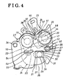
- Fig. 4 is a view similar to Fig. 2 but showing the lock device under a locked position
- Fig. 5 is a partial cross sectional view taken along the line connecting the latch pivotal axis and a pin;
- Fig. 6 is a partial cross sectional view similar to Fig. 5 , but taken along the line connecting the pawl pivotal axis and a sliding pin;
- Fig. 7 is a view similar to Fig. 4 , but showing the locked position of the lock device wherein a position under the striker is deviated in one direction;
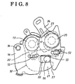
- Fig. 8 is a view similar to Fig. 7 , but showing the striker being deviated in the other direction;
- Fig. 9 is a plane view of a lock device according to another embodiment of the invention.
- a lock device 10 is fixed to a side frame of a seat back 12 (movable member) of a rear seat 11 through a base plate 16.
- the seat back 12 is movable relative to a seat cushion 14 of the seat 11.
- a striker 26 is fixed to an inner side of a vehicle body (fixed member). The striker 26 engages with the lock device 10 when the seat back 12 is moved upright.
- the striker and the lock device 10 form a vehicle lock device 15.
- the vehicle lock device 15 is locked when the lock device 10 engages with the striker 26 under the seat back being in an upright position.
- the locked position is released by operating an operation lever 13 attached to the lock device 10 for allowing the seat back to be forwardly inclined (folded) relative to the seat cushion 14 of the seat 11.
- the inclined or folded position of the seat back 12 is shown in Fig. 1 with a two-dot chain line.
- the lock device 10 includes the base plate 16.
- the base plate 16 includes a first plate 17 and a second plate 18.
- the first and the second plates 17 and 18 are connected in parallel with each other having a predetermined distance therebetween through a latch axis 19, a pawl axis 20 and a spring receiving axis 36.
- a latch 21 and a rotation plate 22 are coaxially arranged and rotationally supported by the latch axis 19 between the first and the second plates 17 and 18 as shown in Fig. 5 .
- a pawl 23 and a rotation lever 24 are coaxially arranged and rotationally supported by the pawl axis 20 as shown in Fig. 6 .
- a thrust plate 25 is supported by the pawl axis 20 and movable in a straight line relative to the pawl axis 20.
- the latch axis 19 and the pawl axis 20 crossed with the base plate 16 in an axial direction and are positioned rear side of the base plate 16 having a space in a longitudinal direction.
- the latch 21 and the pawl 23 positioned in the same plane, whereas the rotation plate 22 and the rotation lever 24 are positioned in the same plane.
- the first and second plates 17 and 18 are provided with entrance/retracting grooves 27 for allowing the striker 26 to be entered in or retracted from.
- Each groove 27 on the first and the second plates is positioned frontward opposite to the positions of the latch axis 19 and the pawl axis 20.
- the grooves 27 are formed in a crosswise direction with a right angle in the lengthwise direction.
- Each groove 27 includes entrance opening 28 open along one marginal side of the first and the second plates 17 and 18 extending in a crosswise direction.
- Each groove 27 has a bottom surface 29 with a predetermined depth.
- the latch axis 19 includes a flanged portion, large diameter portion, an intermediate diameter portion and a small diameter portion.
- the large diameter portion and the small diameter portion of the latch axis 19 are engaged with holes provided in the first and the second plates 17 and 18, respectively, and a stepped surface formed by the flanged portion and the large diameter portion and a stepped surface formed by the intermediate diameter portion and the small diameter portion are in contact with the first and the second plates 17 and 18. Under this engagement and contact state, the first and the second plates are welded.
- the latch 21 and the rotation plate 22 are rotationally supported at the intermediate diameter portion of the latch axis 19.
- the latch 21 and the rotation plate 22 are movable between the stepped surface formed by the large diameter portion and the intermediate diameter portion and the second plate 18.
- a lock groove 30 is provided on the latch 21 and the striker 26 enters into or retracts from the groove 30 for engaging with or disengaging from the latch 21 for locking or unlocking operation of the lock device 10 with the striker 26.
- An extension portion 38 is provided in a radial direction at the rearward of the lock groove 30 as viewed in a clockwise direction.
- the lock groove 30 includes a rear side groove surface 33 positioned at the bottom surface 29 side of the groove 27, a front side groove surface 56 opposing the rear side groove surface 33 and an opening 31 for entering the striker 26 therein.
- Outer periphery of the extension portion 38 is co-centrically formed with the latch axis 19 and a tip end of the extension portion 38 in a clockwise direction is provided with a cam surface 40 which contacts with a preventing surface 39 of the lock groove 30.
- the latch 21 is rotational between a release position 32 (the position shown in Fig. 3 ) where the opening 31 of the lock groove 30 is in alignment with the entrance opening 28 and a locked position 34 (the position shown in Fig. 4 ) where the lock groove 30 is positioned with a right angle relative to the groove 27 by the pushing movement of the striker 26 entered into the groove 27 on the rear side groove surface 33 of the lock groove 30.
- a release position 32 the position shown in Fig. 3
- a locked position 34 the position shown in Fig. 4
- the latch 21 is biased toward the release position 32 in the clockwise direction (direction same as the rotational direction for releasing the lock) by the return spring 35 wound around the latch axis 19,
- a spring receiving axis 36 penetrates through the first and second plates 17 and 18 at a corner portion close to the latch axis 19 and is fixed to the plates by welding.
- One end of the return spring 35 is engaged with the spring receiving axis 36 and the other end thereof is engaged with a projection 37 provided on the latch 21.
- the latch 21 is biased in clockwise direction by the return spring 35 and stopped at the release position 32 by the contact of the rear portion of the latch 21 with the spring receiving axis 36.
- a pawl axis 20 is fixed to the base plate 16 between the first and the second plates with a space apart from the latch axis 19 in crosswise direction.
- a pawl 23 is rotationally supported by the pawl axis 20 in the same plane area with the latch 21.
- a rotation lever 24 is rotationally supported by the pawl axis 20.
- a pin 41 is provided on the pawl 23 and engaged with a circular hole 42 formed on the rotation lever 24 and arranged co-centrically with pawl axis 20. The rotation lever 24 is relatively rotated by a predetermined angle relative to the pawl 23 in association with the movement thereof.
- the pawl axis 20 includes a flanged portion, large diameter portion, an intermediate diameter portion and a small diameter portion.
- the large diameter portion and the small diameter portion of the pawl axis 20 are engaged with holes provided in the first and the second plates 17 and 18, respectively and a stepped surface formed by the flanged portion and the large diameter portion and a stepped surface formed by the intermediate diameter portion and the small diameter portion are in contact with the first and the second plates 17 and 18. Under this engagement and contact state, the first and the second plates are integrally formed by welding or the like.
- the pawl 23 and the rotation lever 24 are rotationally supported at the intermediate diameter portion of the pawl axis 19.
- the pawl 23 and the rotation lever 24 are movable between the stepped surface formed by the large diameter portion and the intermediate diameter portion and the second plate 18.
- a preventing portion 44 is provided on the pawl 23 in a radial direction and the preventing portion 44 is engaged over the extension portion 38 during the latch 21 rotations from the release position 32 to the locked position 34.
- a preventing surface 39 is provided at the rear end of the preventing portion 44 in the counterclockwise direction.
- a male screw portion is provided at each small diameter portion of the latch axis 19 and the pawl axis 20.
- the lock device 10 is fixed to the base plate 16 by sandwiching the side frame of the seat back 12 between the nut screwed with the male screw portion and the second plate 18.
- the rotation lever 24 is biased in a counterclockwise direction (same direction with a rotational direction towards a locking position of the latch) by a return spring 43 wound around the pawl axis.
- One end of the return spring 43 is engaged with a brim portion of the first plate 17 and the other end thereof is engaged with an elongated hole provided in the rotation lever 24.
- the pawl 23 is also biased in the counterclockwise direction through the engagement between the circular hole 42 and the pin 41.
- the rotation in the counterclockwise direction of the pawl 23 is prevented during the preventing portion 44 being in contact with the extension portion 38 of the latch 21 and is positioned at a lock releasable position 45 (position illustrated in Fig. 3 ).
- the pawl 23 is rotated to a lock release preventing position 46 (position illustrated in Fig. 4 ) by the spring force of the return spring 43.
- a pushing portion 47 is provided at the rotation lever 24 towards the rotation plate 22 in a radial direction.
- the pawl keeps the lock releasable position 45 where the latch 21 can be returned to its release position 32 within a range between the release position 32 and the lock position 34 of the latch 21 and then is rotated to the lock preventing position 46 when the latch 21 is rotated to the lock position 34. Then the pawl 23 engages with the latch 21 to prevent the returning of the latch to the release position 32.
- the rotation plate 22 is supported on the latch axis 19 and is accordingly rotationally supported on the base plate 16 coaxially with the latch 21.
- An engaging portion 48 is provided on the rotation plate 22 in a radial direction towards the rotation lever 24 side.
- the rotation plate 22 engages with the rotation lever 24 to be rotated in the same direction with the rotational direction of the latch towards the locked position 34 when the pawl 23 is rotated from the lock preventing position 46 to the lock releasable position 45.
- the rotation plate 22 is biased in a clockwise direction by a return spring 49 wound around a flange portion of the latch axis 19.
- One end of the return spring 49 is engaged with a hole provided in the rotation plate 22 and the other end thereof is engaged with the brim portion of the first plate 17.
- the rotation plate 22 is provided with an operation portion 50 movable in crosswise direction according to the rotation of the rotation plate 22 and is rotationally connected to one end of the thrust plate 25.
- the other end of the thrust plate 25 is supported by a guide portion 52 formed at the base plate 16 and is movably guided in a crosswise direction.
- the operation portion 50 is rotationally connected to the tip end of the thrust plate 25 by a connecting pin 53 at the latch axis side (opposite to the entrance/retracting groove 27 side).
- the connecting pin 53 is engaged with a circular groove 54 formed on the first plate 17 coaxially with the latch axis 19.
- the thrust plate 25 further includes an inclined cam surface 55 provided adjacent the bottom surface 29 of the groove 27 in a crosswise direction extending in a crossing direction with the moving direction of the striker 26 relative to the groove 27.
- the inclined cam surface 55 inclines towards the opening portion 28 of the groove 27 from the latch axis 19 side to the pawl axis 20 side with an inclination of 5 degree, for example.
- the inclined cam surface 55 entraps the striker 26 with the front side groove surface 56 in the groove 27 when the latch 21 is rotated to the locked position 34 by the striker 26 and the pawl 23 moves to the release preventing position 23 and when the rotation lever 24 is disengaged from the rotation plate 22.
- the rotation of the rotation plate 22 moves the inclined cam surface 55 into the groove 27 to enclose the striker 26 by the cam surface 55 and the latch 21 to firmly keep the locked position without any generation of chattering noise.
- the first plate 17 is provided with an elongated guide hole 57 at the pawl axis 20 side opposite to the entrance/retracting groove 27.
- a slide pin 58 is secured to one end of the thrust plate 25 and is inserted into the guide hole 57.
- the elongated guide hole 57 includes a crosswise hole portion 59 guiding the rear end portion of the thrust plate 25 in a crosswise direction and an inclined hole portion 60 for receiving the thrust plate 25 when it moves away from the opening 28 of the groove 27.
- the thrust plate 25 is loosely supported by the base plate 16 through the engagement of the slide pin 58 with the elongated hole 57 provided in the first plate 17.
- a first biasing means is formed by the return springs 35 and 43 for biasing the latch 21 in the lock release direction to move the latch to the lock release position 32 and biasing the pawl 23 in the rotation direction to the lock release preventing position 46.
- a second biasing means is formed by the return spring 49 for biasing the rotation plate 22 in the direction same as the latch release direction to the release position 32 of the latch 21.
- the latch 21 is biased in a clockwise direction by the spring 35. Then the backside of the latch 21 becomes in contact with the spring receiving axis 36 to be in the release position 32.
- the pawl 23 is biased in the counterclockwise direction by the force of spring 43 through the rotation lever 24.
- the preventing portion 44 overrides on the extension portion 38 to position the latch 21 at the releasable position 45.
- the rotation lever 24 is prevented its counterclockwise rotation by the engagement of the pin 41 with the circular hole 42 and the rotation plate 22 is rotated in the counterclockwise direction by the engagement of the engaging portion 48 with the pushing portion 47 to retract the thrust plate 25 to the retracting end portion.
- the thrust plate 25 advances with the connecting pin 53 when the rotation plate 22 is rotated in the clockwise direction and the inclined cam surface 55 engages the striker 26 with the front side groove surface 56 of the lock groove 30.
- the pressure applied on the striker 26 by the pressure angle of the inclined cam surface 55 is set to be smaller (about 5 degree) so that the thrust plate 25 cannot retract from the groove by the engagement with the striker 26.
- the thrust plate 25 moves away from the opening 28 of the groove 27 by the sliding movement of the sliding pin 58 in the inclined hole 60 of the guide elongated hole 57.
- the cam surface 55 retracts to the position where the bottom surface 29 of the groove 27 positions. Under this situation, when the rotation plate 22 is rotated in the clockwise direction to advance the thrust plate 25.
- the thrust plate 25 is guided in the inclined hole 60 to move to the opening 28 side of the groove 27. This can increase the lateral movement of the inclined cam surface 55 relative to the crosswise movement of the thrust plate 25 so that the striker 26 can be secured firmly between the inclined cam surface 55 and the front side groove surface 56 of the lock groove 30 with a relatively small pressure angle even if the deviation of the lateral position or the diameter of the striker 26 is large. Under this situation, since the connecting pin 53 is engaged with the circular groove 54 formed in the first plate 17 of the base plate 16, a large force applied on the plate 25 towards the latch axis 19 can be received by the base plate 16 to reduce any possible damages on the rotation plate 22 and the latch axis 19.
- Fig. 4 shows the striker 26 positioned at the central portion of the entrance/retracting groove 27 and firmly secured by the inclined cam surface 55 of the plate 25 and the front side groove surface 56 of the lock groove 30.
- Fig. 7 shows the striker 26 being deviated its position in the crosswise direction to the groove surface at the latch axis 19 side.
- the striker 26 can be firmly secured between the front side groove surface 56 of the lock groove 30 and the inclined cam surface 55 with a relatively small pressure angle by sufficiently moving the inclined cam surface 55 in a lengthwise direction by the crosswise advance movement of the thrust plate 25 under the deviated condition illustrated in Fig. 7 .
- Fig. 4 shows the striker 26 positioned at the central portion of the entrance/retracting groove 27 and firmly secured by the inclined cam surface 55 of the plate 25 and the front side groove surface 56 of the lock groove 30.
- Fig. 7 shows the striker 26 being deviated its position in the crosswise direction to the groove surface at the latch axis 19 side.
- FIG. 8 shows the striker 26 being deviated its position to the groove surface at pawl axis 20 side of the entrance/retracting groove 27.
- the striker 26 can be locked firmly with a smaller pressure angle according to the lock device 10 of this embodiment.
- the pushing portion 47 of the rotation lever 24 is slightly separated from the engaging portion 48 of the rotation plate 22. The deviation direction and the amount of deviation change the separation amount of the striker 26 from the engaging portion 48 of the rotation plate 22.
- the thrust plate 25 moves to secure the striker between the front side groove surface 56 of the lock groove 30 and the inclined cam surface 55 depending on the deviation amount.
- the operation lever 13 is operated to rotate the rotation lever 24 in the clockwise direction overcoming the biasing force of spring 43. Then the circular hole 42 becomes in contact with the pin 41 to rotate the pawl 23 up to the lock releasable position 45. Since the rotation lever 24 only is rotated in the counterclockwise direction by a predetermined angle before the engagement of the circular hole 42 with the pin 41, the pushing portion 47 engages with the engaging portion 48 to rotate the rotation plate 22 in the counterclockwise direction to retract the plate 25 to release the striker 26 from the engagement of the inclined cam surface 55.
- the force required for operation of the rotation lever 24 to rotate the rotation plate 22 can be set to be small to improve the operability.
- the circular hole 42 is engaged with the pin 41 to rotate the pawl 23 in the clockwise direction, the preventing surface 39 of the pawl 23 can be smoothly disengaged from the cam surface 40 of the latch 21 with a small force.
- the pawl 23 can be rotated by the rotation lever 24 to the releasable position 45 with a small operation force.
- the latch 21 is rotated in the clockwise direction by the release of the cam surface 40 from the preventing surface 39 of the pawl 23.
- the striker 26 is released from the lock device 10 by moving from the opening 31 of the lock groove 30 and the entrance/retracting groove 27 to be in a free position.
- the seat back 12 is then reclined forward on to the seat cushion 14.
- the latch 21 is kept to the release position 32 by the force of return spring 35.
- the first biasing means can be alternatively formed by a tension spring provided between the latch 21 and the pawl 23 for rotating the pawl 23 in the counterclockwise direction to rotate the latch 21 in the clockwise direction instead of using the first biasing means described in this embodiment, i.e., the first biasing means formed by the return springs 35 and 43 for rotating the pawl 23 in the counterclockwise direction to rotate the latch 21 in the clockwise direction.
- the pawl and the rotation lever can be formed by one piece instead of forming the rotation lever 22 coaxially formed with the pawl axis with a predetermined angle relative to the pawl 23.
- Fig. 9 shows another embodiment of the lock device 10 wherein the thrust plate 25 is provided with an extension 25a extending from the connecting end of the plate 25 with the rotation plate 22 and the first plate 17 is provided with a second guide portion 52a having the same shape with the guide portion 52 at a portion corresponding to the end portion of the extension portion 25a.
- the second guide portion 52a is loosely engaged with the end of the extension portion 25a to support the thrust plate 25 on the first plate 17.
- the thrust plate 25 is further provided with an elongated hole 25b at the connecting portion with the rotation plate 22 for allowing vertical movement of the connecting pin 53 caused by the rotation of the rotation plate 22.
- the thrust plate 25 is moved in parallel with a right angle with the striker moving direction in the groove 27.
- a lock device for a vehicle includes a base plate (16) provided with an entrance/retracting groove (27) for receiving or retracting a striker (26) and a latch (21) pivotally supported on the base plate by a latch axis (19).
- the latch includes a lock groove (30) engaging with or disengaging from the striker entering the entrance/retracting groove and rotatable between a lock release position (32) allowing the striker entering into the entrance/retracting groove and a lock position (34) for holding the striker in the entrance/retracting groove by the movement of the striker.
- a first biasing means (35, 43) is provided for biasing the latch in the rotational direction to the release position to bias the pawl in a rotational direction towards the release preventing position and a second biasing means (49) is provided for biasing the rotation
Applications Claiming Priority (1)
| Application Number | Priority Date | Filing Date | Title |
|---|---|---|---|
| JP2007317009A JP5056387B2 (ja) | 2007-12-07 | 2007-12-07 | 車両用ロック装置 |
Publications (3)
| Publication Number | Publication Date |
|---|---|
| EP2067917A2 true EP2067917A2 (fr) | 2009-06-10 |
| EP2067917A3 EP2067917A3 (fr) | 2014-05-21 |
| EP2067917B1 EP2067917B1 (fr) | 2016-11-16 |
Family
ID=40548483
Family Applications (1)
| Application Number | Title | Priority Date | Filing Date |
|---|---|---|---|
| EP08170838.0A Not-in-force EP2067917B1 (fr) | 2007-12-07 | 2008-12-05 | Dispositif de verrouillage pour véhicule |
Country Status (3)
| Country | Link |
|---|---|
| US (1) | US8128135B2 (fr) |
| EP (1) | EP2067917B1 (fr) |
| JP (1) | JP5056387B2 (fr) |
Cited By (6)
| Publication number | Priority date | Publication date | Assignee | Title |
|---|---|---|---|---|
| CN102482898A (zh) * | 2009-08-25 | 2012-05-30 | 白木工业株式会社 | 用于车辆的锁定设备 |
| ITTO20120822A1 (it) * | 2012-09-21 | 2014-03-22 | Magna Closures Spa | Serratura per un sedile di un autoveicolo |
| WO2015013326A1 (fr) * | 2013-07-23 | 2015-01-29 | Johnson Controls Technology Company | Came structurale pour loquet |
| WO2015014342A1 (fr) * | 2013-07-31 | 2015-02-05 | Kiekert Ag | Portière de véhicule automobile |
| EP2657068A3 (fr) * | 2012-04-27 | 2017-11-29 | FUJI KIKO Co., Ltd. | Dispositif de verrouillage de siège de véhicule |
| US11536061B2 (en) * | 2016-09-14 | 2022-12-27 | Kiekert Ag | Motor vehicle door lock |
Families Citing this family (30)
| Publication number | Priority date | Publication date | Assignee | Title |
|---|---|---|---|---|
| US20100026013A1 (en) * | 2007-03-16 | 2010-02-04 | Toyota Boshoku Kabushiki Kaisha | Locking device |
| WO2010050925A1 (fr) * | 2008-10-28 | 2010-05-06 | Lear Corporation | Dispositif de verrouillage de siège |
| DE102009019510B4 (de) * | 2009-04-24 | 2011-09-01 | Progress-Werk Oberkirch Ag | Vorrichtung zum Verriegeln eines Fahrzeugsitzes |
| US8801052B2 (en) * | 2010-01-11 | 2014-08-12 | Deere & Company | Hood latch |
| US8267458B2 (en) * | 2010-03-25 | 2012-09-18 | Honda Motor Co., Ltd. | Seat assembly for a vehicle having a vertically extended striker mechanism |
| US8313147B2 (en) | 2010-04-21 | 2012-11-20 | Honda Motor Co., Ltd. | Seat latch assembly for a vehicle seat |
| JP5140893B2 (ja) * | 2010-06-09 | 2013-02-13 | 三井金属アクト株式会社 | ラッチ装置 |
| JP5614332B2 (ja) | 2011-02-28 | 2014-10-29 | アイシン精機株式会社 | 車両用ロック装置 |
| BR112013024403A2 (pt) * | 2011-03-31 | 2016-12-13 | Ts Tech Co Ltd | assento de transporte |
| JP5437309B2 (ja) * | 2011-04-22 | 2014-03-12 | アイシン精機株式会社 | 回転レバーの位置保持装置および該回転レバーの位置保持装置を備える車両用ドアロック装置 |
| KR101356136B1 (ko) | 2011-08-22 | 2014-01-28 | (주)케이엠앤아이 | 차량용 시트 백 래치 |
| JP5922482B2 (ja) * | 2012-04-27 | 2016-05-24 | 富士機工株式会社 | シートの固定装置 |
| US8763979B2 (en) * | 2012-05-23 | 2014-07-01 | Porter Group, Llc | Vehicle seat latch having striker compliance in transverse directions |
| JP5681223B2 (ja) * | 2013-03-07 | 2015-03-04 | シロキ工業株式会社 | ロック装置 |
| DE102013011803B4 (de) * | 2013-07-16 | 2016-11-03 | Johnson Controls Gmbh | Verriegelungsvorrichtung |
| DE102014106225A1 (de) * | 2014-05-05 | 2015-11-05 | ABUS August Bremicker Söhne KG | Kabelverriegelungssystem |
| JP2016027968A (ja) * | 2014-07-08 | 2016-02-25 | アイシン精機株式会社 | 車両用シートロック装置 |
| JP6427824B2 (ja) * | 2014-10-16 | 2018-11-28 | 三井金属アクト株式会社 | シートロック装置 |
| US9914369B2 (en) * | 2015-09-29 | 2018-03-13 | Faurecia Automotive Seating, Llc | Vehicle seat with hook and cam latching mechanism |
| KR101876000B1 (ko) * | 2015-11-03 | 2018-07-06 | 현대자동차주식회사 | 차량의 래치 어셈블리 |
| JP6613829B2 (ja) * | 2015-11-09 | 2019-12-04 | アイシン精機株式会社 | シートロック装置 |
| JP6764767B2 (ja) * | 2016-11-17 | 2020-10-07 | シロキ工業株式会社 | 車両用ロック装置 |
| CN206581743U (zh) * | 2017-03-03 | 2017-10-24 | 恩坦华产品有限责任公司 | 用于车辆锁闩致动器机构的弹簧保持组件 |
| US9994129B1 (en) * | 2017-03-06 | 2018-06-12 | Toyo Seat Usa Corp | Seatback latch |
| DE102018203862A1 (de) * | 2017-04-03 | 2018-10-04 | Lear Corporation | Sitzverriegelungsanordnung |
| WO2018218288A1 (fr) * | 2017-05-30 | 2018-12-06 | Bright Spark Product Development Pty Ltd | Ensemble loquet |
| JP6687221B2 (ja) * | 2017-05-30 | 2020-04-22 | 三井金属アクト株式会社 | シートロック装置 |
| US11390188B2 (en) * | 2018-01-29 | 2022-07-19 | Ts Tech Co., Ltd. | Latch device and vehicle seat |
| EP3613928B1 (fr) * | 2018-08-17 | 2021-06-09 | Inteva Products, LLC | Ressort de libération intérieur pour portière de véhicule |
| CN110439397B (zh) * | 2019-07-29 | 2021-10-12 | 广东东箭汽车智能系统有限公司 | 汽车尾门电吸锁和汽车 |
Citations (1)
| Publication number | Priority date | Publication date | Assignee | Title |
|---|---|---|---|---|
| US6945585B1 (en) | 2004-03-31 | 2005-09-20 | Porter Group, Llc | Vehicle seat attachment latch assembly |
Family Cites Families (16)
| Publication number | Priority date | Publication date | Assignee | Title |
|---|---|---|---|---|
| JPS569634B2 (fr) * | 1973-11-30 | 1981-03-03 | ||
| GB2172930B (en) * | 1985-03-26 | 1988-10-05 | Bloxvich Lock Stamping | Releasable fastening mechanism for tilting cabs on vehicles |
| JPH0625511B2 (ja) * | 1986-07-31 | 1994-04-06 | 三井金属鉱業株式会社 | ロツク装置 |
| US4865377A (en) * | 1987-12-31 | 1989-09-12 | Knusaga Corporation | Seat riser |
| JP3609217B2 (ja) * | 1996-09-30 | 2005-01-12 | 株式会社大井製作所 | ロック装置 |
| JP4051748B2 (ja) * | 1998-01-27 | 2008-02-27 | アイシン精機株式会社 | 車両用ロック装置 |
| JP3458821B2 (ja) * | 2000-04-27 | 2003-10-20 | 株式会社デンソー | ドアロック操作装置 |
| US6679531B2 (en) * | 2001-05-03 | 2004-01-20 | Delphi Technologies, Inc. | Vehicle compartment latch |
| DE10320448A1 (de) * | 2003-05-08 | 2004-12-16 | Kiekert Ag | Kraftfahrzeugtürverschluss |
| DE10343622B4 (de) * | 2003-09-20 | 2010-11-18 | BÖCO Böddecker & Co. GmbH & Co. KG | Schloss mit einer Drehfalle und Sperrklinke |
| JP4407428B2 (ja) * | 2003-09-22 | 2010-02-03 | トヨタ紡織株式会社 | ロック装置 |
| US20050269854A1 (en) * | 2004-06-03 | 2005-12-08 | Tavis Lutzka | Vehicle seat latch assembly having a pivoting anti-chuck hook for engaging a floor-mounted striker plate |
| JP4721326B2 (ja) * | 2005-03-09 | 2011-07-13 | テイ・エス テック株式会社 | 車両用シートのロック装置 |
| DE602007006064D1 (de) * | 2006-01-23 | 2010-06-10 | Mitsui Mining & Smelting Co | Fahrzeugsitzverriegelung |
| JP4176120B2 (ja) * | 2006-09-11 | 2008-11-05 | 株式会社今仙電機製作所 | 車両用ロック装置 |
| DE102006045228A1 (de) * | 2006-09-26 | 2008-04-03 | Fischer Automotive Systems Gmbh | Halter für einen Getränkebehälter |
-
2007
- 2007-12-07 JP JP2007317009A patent/JP5056387B2/ja not_active Expired - Fee Related
-
2008
- 2008-12-04 US US12/328,201 patent/US8128135B2/en not_active Expired - Fee Related
- 2008-12-05 EP EP08170838.0A patent/EP2067917B1/fr not_active Not-in-force
Patent Citations (1)
| Publication number | Priority date | Publication date | Assignee | Title |
|---|---|---|---|---|
| US6945585B1 (en) | 2004-03-31 | 2005-09-20 | Porter Group, Llc | Vehicle seat attachment latch assembly |
Cited By (12)
| Publication number | Priority date | Publication date | Assignee | Title |
|---|---|---|---|---|
| CN102482898A (zh) * | 2009-08-25 | 2012-05-30 | 白木工业株式会社 | 用于车辆的锁定设备 |
| CN102482898B (zh) * | 2009-08-25 | 2014-07-30 | 白木工业株式会社 | 用于车辆的锁定设备 |
| US8833808B2 (en) | 2009-08-25 | 2014-09-16 | Shiroki Corporation | Lock device for vehicle |
| EP2657068A3 (fr) * | 2012-04-27 | 2017-11-29 | FUJI KIKO Co., Ltd. | Dispositif de verrouillage de siège de véhicule |
| ITTO20120822A1 (it) * | 2012-09-21 | 2014-03-22 | Magna Closures Spa | Serratura per un sedile di un autoveicolo |
| EP2711242A1 (fr) * | 2012-09-21 | 2014-03-26 | Magna Closures S.p.A. | Dispositif de blocage pour un siège de véhicule automobile |
| WO2015013326A1 (fr) * | 2013-07-23 | 2015-01-29 | Johnson Controls Technology Company | Came structurale pour loquet |
| US9868367B2 (en) | 2013-07-23 | 2018-01-16 | Johnson Controls Technology Company | Structural cam for latch |
| WO2015014342A1 (fr) * | 2013-07-31 | 2015-02-05 | Kiekert Ag | Portière de véhicule automobile |
| CN105593444A (zh) * | 2013-07-31 | 2016-05-18 | 开开特股份公司 | 机动车门 |
| US10557290B2 (en) | 2013-07-31 | 2020-02-11 | Kiekert Aktiengesellschaft | Motor vehicle door |
| US11536061B2 (en) * | 2016-09-14 | 2022-12-27 | Kiekert Ag | Motor vehicle door lock |
Also Published As
| Publication number | Publication date |
|---|---|
| JP5056387B2 (ja) | 2012-10-24 |
| JP2009138457A (ja) | 2009-06-25 |
| EP2067917B1 (fr) | 2016-11-16 |
| US8128135B2 (en) | 2012-03-06 |
| EP2067917A3 (fr) | 2014-05-21 |
| US20090145183A1 (en) | 2009-06-11 |
Similar Documents
| Publication | Publication Date | Title |
|---|---|---|
| EP2067917B1 (fr) | Dispositif de verrouillage pour véhicule | |
| JP5169146B2 (ja) | 車両用シート装置 | |
| US7641282B2 (en) | Locking device for seat back | |
| US11945345B2 (en) | Child safety seat | |
| US10458158B2 (en) | Vehicle door lock apparatus | |
| US6786551B2 (en) | Seat latching assembly | |
| US7963608B2 (en) | Vehicle seat assembly capable of performing an easy entry function and memory return | |
| US8777315B2 (en) | High back seat latch with integrated handle | |
| JP6687221B2 (ja) | シートロック装置 | |
| US20140042289A1 (en) | Slide rail device for vehicle | |
| US20120061985A1 (en) | Vehicle cargo system with multi-function tonneau cover | |
| JP4487939B2 (ja) | 車両用シート | |
| WO2016171137A1 (fr) | Siège pour véhicules | |
| EP2072327B1 (fr) | Dispositif de libération de l'espace de chargement des bagages d'un véhicule automobile | |
| JP5228421B2 (ja) | 車両用シート | |
| JP6583062B2 (ja) | 乗物用スライドレール装置 | |
| WO2016171135A1 (fr) | Siège pour véhicules | |
| JP6044534B2 (ja) | フード跳ね上げ装置 | |
| JP5965727B2 (ja) | ロック機構 | |
| JP5685920B2 (ja) | アームレスト構造 | |
| JP2011098583A (ja) | 乗物シート用リクライニング装置 | |
| JP4412210B2 (ja) | 車両用シート | |
| JP3563305B2 (ja) | 車両用ヒンジ付きシートのロック構造 | |
| JP2529983Y2 (ja) | 車両の運転室構造 | |
| WO2022266276A1 (fr) | Verrou élevé pour dossier de siège à multiples positions de verrouillage |
Legal Events
| Date | Code | Title | Description |
|---|---|---|---|
| PUAI | Public reference made under article 153(3) epc to a published international application that has entered the european phase |
Free format text: ORIGINAL CODE: 0009012 |
|
| AK | Designated contracting states |
Kind code of ref document: A2 Designated state(s): AT BE BG CH CY CZ DE DK EE ES FI FR GB GR HR HU IE IS IT LI LT LU LV MC MT NL NO PL PT RO SE SI SK TR |
|
| AX | Request for extension of the european patent |
Extension state: AL BA MK RS |
|
| RIN1 | Information on inventor provided before grant (corrected) |
Inventor name: MIZUNO, TAKUYA Inventor name: MAETA, KENJI Inventor name: KONDOH, KOUJI |
|
| PUAL | Search report despatched |
Free format text: ORIGINAL CODE: 0009013 |
|
| AK | Designated contracting states |
Kind code of ref document: A3 Designated state(s): AT BE BG CH CY CZ DE DK EE ES FI FR GB GR HR HU IE IS IT LI LT LU LV MC MT NL NO PL PT RO SE SI SK TR |
|
| AX | Request for extension of the european patent |
Extension state: AL BA MK RS |
|
| RIC1 | Information provided on ipc code assigned before grant |
Ipc: B60N 2/22 20060101ALN20140411BHEP Ipc: E05C 3/24 20060101AFI20140411BHEP Ipc: E05B 77/36 20140101ALI20140411BHEP Ipc: B60N 2/00 20060101ALN20140411BHEP Ipc: E05B 83/16 20140101ALN20140411BHEP |
|
| 17P | Request for examination filed |
Effective date: 20140617 |
|
| RBV | Designated contracting states (corrected) |
Designated state(s): AT BE BG CH CY CZ DE DK EE ES FI FR GB GR HR HU IE IS IT LI LT LU LV MC MT NL NO PL PT RO SE SI SK TR |
|
| AKX | Designation fees paid |
Designated state(s): CZ DE FR GB TR |
|
| AXX | Extension fees paid |
Extension state: RS Extension state: BA Extension state: MK Extension state: AL |
|
| RBV | Designated contracting states (corrected) |
Designated state(s): AT BE BG CH CY CZ DE DK EE ES FI FR GB GR HR HU IE IS IT LI LT LU LV MC MT NL NO PL PT RO SE SI SK TR |
|
| RIC1 | Information provided on ipc code assigned before grant |
Ipc: B60N 2/015 20060101ALI20160531BHEP Ipc: B60N 2/22 20060101ALN20160531BHEP Ipc: B60N 2/00 20060101ALN20160531BHEP Ipc: E05C 3/24 20060101AFI20160531BHEP Ipc: E05B 77/36 20140101ALI20160531BHEP Ipc: E05B 83/16 20140101ALN20160531BHEP |
|
| GRAP | Despatch of communication of intention to grant a patent |
Free format text: ORIGINAL CODE: EPIDOSNIGR1 |
|
| INTG | Intention to grant announced |
Effective date: 20160714 |
|
| GRAS | Grant fee paid |
Free format text: ORIGINAL CODE: EPIDOSNIGR3 |
|
| GRAJ | Information related to disapproval of communication of intention to grant by the applicant or resumption of examination proceedings by the epo deleted |
Free format text: ORIGINAL CODE: EPIDOSDIGR1 |
|
| GRAL | Information related to payment of fee for publishing/printing deleted |
Free format text: ORIGINAL CODE: EPIDOSDIGR3 |
|
| REG | Reference to a national code |
Ref country code: DE Ref legal event code: R079 Ref document number: 602008047368 Country of ref document: DE Free format text: PREVIOUS MAIN CLASS: E05B0065120000 Ipc: E05C0003240000 |
|
| GRAR | Information related to intention to grant a patent recorded |
Free format text: ORIGINAL CODE: EPIDOSNIGR71 |
|
| GRAA | (expected) grant |
Free format text: ORIGINAL CODE: 0009210 |
|
| INTC | Intention to grant announced (deleted) | ||
| RIC1 | Information provided on ipc code assigned before grant |
Ipc: B60N 2/015 20060101ALI20161005BHEP Ipc: E05B 83/16 20140101ALN20161005BHEP Ipc: E05B 77/36 20140101ALI20161005BHEP Ipc: B60N 2/00 20060101ALN20161005BHEP Ipc: E05C 3/24 20060101AFI20161005BHEP Ipc: B60N 2/22 20060101ALN20161005BHEP |
|
| AK | Designated contracting states |
Kind code of ref document: B1 Designated state(s): AT BE BG CH CY CZ DE DK EE ES FI FR GB GR HR HU IE IS IT LI LT LU LV MC MT NL NO PL PT RO SE SI SK TR |
|
| INTG | Intention to grant announced |
Effective date: 20161012 |
|
| REG | Reference to a national code |
Ref country code: GB Ref legal event code: FG4D |
|
| REG | Reference to a national code |
Ref country code: FR Ref legal event code: PLFP Year of fee payment: 9 |
|
| REG | Reference to a national code |
Ref country code: CH Ref legal event code: EP |
|
| REG | Reference to a national code |
Ref country code: IE Ref legal event code: FG4D |
|
| REG | Reference to a national code |
Ref country code: AT Ref legal event code: REF Ref document number: 846124 Country of ref document: AT Kind code of ref document: T Effective date: 20161215 |
|
| REG | Reference to a national code |
Ref country code: DE Ref legal event code: R096 Ref document number: 602008047368 Country of ref document: DE |
|
| REG | Reference to a national code |
Ref country code: DE Ref legal event code: R096 Ref document number: 602008047368 Country of ref document: DE |
|
| PG25 | Lapsed in a contracting state [announced via postgrant information from national office to epo] |
Ref country code: LV Free format text: LAPSE BECAUSE OF FAILURE TO SUBMIT A TRANSLATION OF THE DESCRIPTION OR TO PAY THE FEE WITHIN THE PRESCRIBED TIME-LIMIT Effective date: 20161116 |
|
| REG | Reference to a national code |
Ref country code: NL Ref legal event code: MP Effective date: 20161116 |
|
| REG | Reference to a national code |
Ref country code: LT Ref legal event code: MG4D |
|
| REG | Reference to a national code |
Ref country code: AT Ref legal event code: MK05 Ref document number: 846124 Country of ref document: AT Kind code of ref document: T Effective date: 20161116 |
|
| PG25 | Lapsed in a contracting state [announced via postgrant information from national office to epo] |
Ref country code: GR Free format text: LAPSE BECAUSE OF FAILURE TO SUBMIT A TRANSLATION OF THE DESCRIPTION OR TO PAY THE FEE WITHIN THE PRESCRIBED TIME-LIMIT Effective date: 20170217 Ref country code: NL Free format text: LAPSE BECAUSE OF FAILURE TO SUBMIT A TRANSLATION OF THE DESCRIPTION OR TO PAY THE FEE WITHIN THE PRESCRIBED TIME-LIMIT Effective date: 20161116 Ref country code: LT Free format text: LAPSE BECAUSE OF FAILURE TO SUBMIT A TRANSLATION OF THE DESCRIPTION OR TO PAY THE FEE WITHIN THE PRESCRIBED TIME-LIMIT Effective date: 20161116 Ref country code: NO Free format text: LAPSE BECAUSE OF FAILURE TO SUBMIT A TRANSLATION OF THE DESCRIPTION OR TO PAY THE FEE WITHIN THE PRESCRIBED TIME-LIMIT Effective date: 20170216 Ref country code: SE Free format text: LAPSE BECAUSE OF FAILURE TO SUBMIT A TRANSLATION OF THE DESCRIPTION OR TO PAY THE FEE WITHIN THE PRESCRIBED TIME-LIMIT Effective date: 20161116 |
|
| PG25 | Lapsed in a contracting state [announced via postgrant information from national office to epo] |
Ref country code: HR Free format text: LAPSE BECAUSE OF FAILURE TO SUBMIT A TRANSLATION OF THE DESCRIPTION OR TO PAY THE FEE WITHIN THE PRESCRIBED TIME-LIMIT Effective date: 20161116 Ref country code: ES Free format text: LAPSE BECAUSE OF FAILURE TO SUBMIT A TRANSLATION OF THE DESCRIPTION OR TO PAY THE FEE WITHIN THE PRESCRIBED TIME-LIMIT Effective date: 20161116 Ref country code: FI Free format text: LAPSE BECAUSE OF FAILURE TO SUBMIT A TRANSLATION OF THE DESCRIPTION OR TO PAY THE FEE WITHIN THE PRESCRIBED TIME-LIMIT Effective date: 20161116 Ref country code: PT Free format text: LAPSE BECAUSE OF FAILURE TO SUBMIT A TRANSLATION OF THE DESCRIPTION OR TO PAY THE FEE WITHIN THE PRESCRIBED TIME-LIMIT Effective date: 20170316 Ref country code: PL Free format text: LAPSE BECAUSE OF FAILURE TO SUBMIT A TRANSLATION OF THE DESCRIPTION OR TO PAY THE FEE WITHIN THE PRESCRIBED TIME-LIMIT Effective date: 20161116 Ref country code: BE Free format text: LAPSE BECAUSE OF NON-PAYMENT OF DUE FEES Effective date: 20161231 Ref country code: AT Free format text: LAPSE BECAUSE OF FAILURE TO SUBMIT A TRANSLATION OF THE DESCRIPTION OR TO PAY THE FEE WITHIN THE PRESCRIBED TIME-LIMIT Effective date: 20161116 |
|
| PG25 | Lapsed in a contracting state [announced via postgrant information from national office to epo] |
Ref country code: RO Free format text: LAPSE BECAUSE OF FAILURE TO SUBMIT A TRANSLATION OF THE DESCRIPTION OR TO PAY THE FEE WITHIN THE PRESCRIBED TIME-LIMIT Effective date: 20161116 Ref country code: CZ Free format text: LAPSE BECAUSE OF FAILURE TO SUBMIT A TRANSLATION OF THE DESCRIPTION OR TO PAY THE FEE WITHIN THE PRESCRIBED TIME-LIMIT Effective date: 20161116 Ref country code: DK Free format text: LAPSE BECAUSE OF FAILURE TO SUBMIT A TRANSLATION OF THE DESCRIPTION OR TO PAY THE FEE WITHIN THE PRESCRIBED TIME-LIMIT Effective date: 20161116 Ref country code: EE Free format text: LAPSE BECAUSE OF FAILURE TO SUBMIT A TRANSLATION OF THE DESCRIPTION OR TO PAY THE FEE WITHIN THE PRESCRIBED TIME-LIMIT Effective date: 20161116 Ref country code: SK Free format text: LAPSE BECAUSE OF FAILURE TO SUBMIT A TRANSLATION OF THE DESCRIPTION OR TO PAY THE FEE WITHIN THE PRESCRIBED TIME-LIMIT Effective date: 20161116 |
|
| REG | Reference to a national code |
Ref country code: CH Ref legal event code: PL |
|
| REG | Reference to a national code |
Ref country code: DE Ref legal event code: R097 Ref document number: 602008047368 Country of ref document: DE |
|
| PG25 | Lapsed in a contracting state [announced via postgrant information from national office to epo] |
Ref country code: BE Free format text: LAPSE BECAUSE OF FAILURE TO SUBMIT A TRANSLATION OF THE DESCRIPTION OR TO PAY THE FEE WITHIN THE PRESCRIBED TIME-LIMIT Effective date: 20161116 Ref country code: IT Free format text: LAPSE BECAUSE OF FAILURE TO SUBMIT A TRANSLATION OF THE DESCRIPTION OR TO PAY THE FEE WITHIN THE PRESCRIBED TIME-LIMIT Effective date: 20161116 |
|
| REG | Reference to a national code |
Ref country code: DE Ref legal event code: R084 Ref document number: 602008047368 Country of ref document: DE |
|
| PLBE | No opposition filed within time limit |
Free format text: ORIGINAL CODE: 0009261 |
|
| STAA | Information on the status of an ep patent application or granted ep patent |
Free format text: STATUS: NO OPPOSITION FILED WITHIN TIME LIMIT |
|
| PG25 | Lapsed in a contracting state [announced via postgrant information from national office to epo] |
Ref country code: MC Free format text: LAPSE BECAUSE OF FAILURE TO SUBMIT A TRANSLATION OF THE DESCRIPTION OR TO PAY THE FEE WITHIN THE PRESCRIBED TIME-LIMIT Effective date: 20161116 |
|
| REG | Reference to a national code |
Ref country code: IE Ref legal event code: MM4A |
|
| 26N | No opposition filed |
Effective date: 20170817 |
|
| GBPC | Gb: european patent ceased through non-payment of renewal fee |
Effective date: 20170216 |
|
| PG25 | Lapsed in a contracting state [announced via postgrant information from national office to epo] |
Ref country code: LI Free format text: LAPSE BECAUSE OF NON-PAYMENT OF DUE FEES Effective date: 20161231 Ref country code: CH Free format text: LAPSE BECAUSE OF NON-PAYMENT OF DUE FEES Effective date: 20161231 Ref country code: LU Free format text: LAPSE BECAUSE OF NON-PAYMENT OF DUE FEES Effective date: 20161205 |
|
| REG | Reference to a national code |
Ref country code: FR Ref legal event code: PLFP Year of fee payment: 10 |
|
| PG25 | Lapsed in a contracting state [announced via postgrant information from national office to epo] |
Ref country code: SI Free format text: LAPSE BECAUSE OF FAILURE TO SUBMIT A TRANSLATION OF THE DESCRIPTION OR TO PAY THE FEE WITHIN THE PRESCRIBED TIME-LIMIT Effective date: 20161116 Ref country code: IE Free format text: LAPSE BECAUSE OF NON-PAYMENT OF DUE FEES Effective date: 20161205 |
|
| PG25 | Lapsed in a contracting state [announced via postgrant information from national office to epo] |
Ref country code: GB Free format text: LAPSE BECAUSE OF NON-PAYMENT OF DUE FEES Effective date: 20170216 |
|
| PG25 | Lapsed in a contracting state [announced via postgrant information from national office to epo] |
Ref country code: HU Free format text: LAPSE BECAUSE OF FAILURE TO SUBMIT A TRANSLATION OF THE DESCRIPTION OR TO PAY THE FEE WITHIN THE PRESCRIBED TIME-LIMIT; INVALID AB INITIO Effective date: 20081205 Ref country code: CY Free format text: LAPSE BECAUSE OF FAILURE TO SUBMIT A TRANSLATION OF THE DESCRIPTION OR TO PAY THE FEE WITHIN THE PRESCRIBED TIME-LIMIT Effective date: 20161116 |
|
| PG25 | Lapsed in a contracting state [announced via postgrant information from national office to epo] |
Ref country code: TR Free format text: LAPSE BECAUSE OF FAILURE TO SUBMIT A TRANSLATION OF THE DESCRIPTION OR TO PAY THE FEE WITHIN THE PRESCRIBED TIME-LIMIT Effective date: 20161116 Ref country code: IS Free format text: LAPSE BECAUSE OF FAILURE TO SUBMIT A TRANSLATION OF THE DESCRIPTION OR TO PAY THE FEE WITHIN THE PRESCRIBED TIME-LIMIT Effective date: 20161116 |
|
| PG25 | Lapsed in a contracting state [announced via postgrant information from national office to epo] |
Ref country code: BG Free format text: LAPSE BECAUSE OF FAILURE TO SUBMIT A TRANSLATION OF THE DESCRIPTION OR TO PAY THE FEE WITHIN THE PRESCRIBED TIME-LIMIT Effective date: 20161116 |
|
| PG25 | Lapsed in a contracting state [announced via postgrant information from national office to epo] |
Ref country code: MT Free format text: LAPSE BECAUSE OF NON-PAYMENT OF DUE FEES Effective date: 20161205 |
|
| PGFP | Annual fee paid to national office [announced via postgrant information from national office to epo] |
Ref country code: DE Payment date: 20191119 Year of fee payment: 12 |
|
| PGFP | Annual fee paid to national office [announced via postgrant information from national office to epo] |
Ref country code: FR Payment date: 20191115 Year of fee payment: 12 |
|
| REG | Reference to a national code |
Ref country code: DE Ref legal event code: R119 Ref document number: 602008047368 Country of ref document: DE |
|
| PG25 | Lapsed in a contracting state [announced via postgrant information from national office to epo] |
Ref country code: FR Free format text: LAPSE BECAUSE OF NON-PAYMENT OF DUE FEES Effective date: 20201231 |
|
| PG25 | Lapsed in a contracting state [announced via postgrant information from national office to epo] |
Ref country code: DE Free format text: LAPSE BECAUSE OF NON-PAYMENT OF DUE FEES Effective date: 20210701 |