EP2067572A2 - Vorrichtung zum Bearbeiten von Brillengläsern - Google Patents
Vorrichtung zum Bearbeiten von Brillengläsern Download PDFInfo
- Publication number
- EP2067572A2 EP2067572A2 EP08021118A EP08021118A EP2067572A2 EP 2067572 A2 EP2067572 A2 EP 2067572A2 EP 08021118 A EP08021118 A EP 08021118A EP 08021118 A EP08021118 A EP 08021118A EP 2067572 A2 EP2067572 A2 EP 2067572A2
- Authority
- EP
- European Patent Office
- Prior art keywords
- lens
- axis
- unit
- torque
- value
- Prior art date
- Legal status (The legal status is an assumption and is not a legal conclusion. Google has not performed a legal analysis and makes no representation as to the accuracy of the status listed.)
- Granted
Links
Images




Classifications
-
- B—PERFORMING OPERATIONS; TRANSPORTING
- B24—GRINDING; POLISHING
- B24B—MACHINES, DEVICES, OR PROCESSES FOR GRINDING OR POLISHING; DRESSING OR CONDITIONING OF ABRADING SURFACES; FEEDING OF GRINDING, POLISHING, OR LAPPING AGENTS
- B24B13/00—Machines or devices designed for grinding or polishing optical surfaces on lenses or surfaces of similar shape on other work; Accessories therefor
-
- B—PERFORMING OPERATIONS; TRANSPORTING
- B24—GRINDING; POLISHING
- B24B—MACHINES, DEVICES, OR PROCESSES FOR GRINDING OR POLISHING; DRESSING OR CONDITIONING OF ABRADING SURFACES; FEEDING OF GRINDING, POLISHING, OR LAPPING AGENTS
- B24B49/00—Measuring or gauging equipment for controlling the feed movement of the grinding tool or work; Arrangements of indicating or measuring equipment, e.g. for indicating the start of the grinding operation
- B24B49/16—Measuring or gauging equipment for controlling the feed movement of the grinding tool or work; Arrangements of indicating or measuring equipment, e.g. for indicating the start of the grinding operation taking regard of the load
-
- B—PERFORMING OPERATIONS; TRANSPORTING
- B24—GRINDING; POLISHING
- B24B—MACHINES, DEVICES, OR PROCESSES FOR GRINDING OR POLISHING; DRESSING OR CONDITIONING OF ABRADING SURFACES; FEEDING OF GRINDING, POLISHING, OR LAPPING AGENTS
- B24B9/00—Machines or devices designed for grinding edges or bevels on work or for removing burrs; Accessories therefor
- B24B9/02—Machines or devices designed for grinding edges or bevels on work or for removing burrs; Accessories therefor characterised by a special design with respect to properties of materials specific to articles to be ground
- B24B9/06—Machines or devices designed for grinding edges or bevels on work or for removing burrs; Accessories therefor characterised by a special design with respect to properties of materials specific to articles to be ground of non-metallic inorganic material, e.g. stone, ceramics, porcelain
- B24B9/08—Machines or devices designed for grinding edges or bevels on work or for removing burrs; Accessories therefor characterised by a special design with respect to properties of materials specific to articles to be ground of non-metallic inorganic material, e.g. stone, ceramics, porcelain of glass
- B24B9/14—Machines or devices designed for grinding edges or bevels on work or for removing burrs; Accessories therefor characterised by a special design with respect to properties of materials specific to articles to be ground of non-metallic inorganic material, e.g. stone, ceramics, porcelain of glass of optical work, e.g. lenses, prisms
-
- B—PERFORMING OPERATIONS; TRANSPORTING
- B24—GRINDING; POLISHING
- B24B—MACHINES, DEVICES, OR PROCESSES FOR GRINDING OR POLISHING; DRESSING OR CONDITIONING OF ABRADING SURFACES; FEEDING OF GRINDING, POLISHING, OR LAPPING AGENTS
- B24B9/00—Machines or devices designed for grinding edges or bevels on work or for removing burrs; Accessories therefor
- B24B9/02—Machines or devices designed for grinding edges or bevels on work or for removing burrs; Accessories therefor characterised by a special design with respect to properties of materials specific to articles to be ground
- B24B9/06—Machines or devices designed for grinding edges or bevels on work or for removing burrs; Accessories therefor characterised by a special design with respect to properties of materials specific to articles to be ground of non-metallic inorganic material, e.g. stone, ceramics, porcelain
- B24B9/08—Machines or devices designed for grinding edges or bevels on work or for removing burrs; Accessories therefor characterised by a special design with respect to properties of materials specific to articles to be ground of non-metallic inorganic material, e.g. stone, ceramics, porcelain of glass
- B24B9/14—Machines or devices designed for grinding edges or bevels on work or for removing burrs; Accessories therefor characterised by a special design with respect to properties of materials specific to articles to be ground of non-metallic inorganic material, e.g. stone, ceramics, porcelain of glass of optical work, e.g. lenses, prisms
- B24B9/148—Machines or devices designed for grinding edges or bevels on work or for removing burrs; Accessories therefor characterised by a special design with respect to properties of materials specific to articles to be ground of non-metallic inorganic material, e.g. stone, ceramics, porcelain of glass of optical work, e.g. lenses, prisms electrically, e.g. numerically, controlled
Definitions
- the present invention relates to an eyeglass lens processing apparatus for processing a periphery of an eyeglass lens.
- a mainly used apparatus is that in which while an eyeglass lens held by a lens chuck shaft is rotated, an axis-to-axis distance between a grindstone spindle attached with roughing grindstone and the lens chuck shaft is changed based on target lens shape data, and the periphery of the lens is roughened by the roughing grindstone.
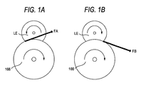
- a down-cut system in which a rotating direction of roughing grindstone 166 and that of an eyeglass lens LE are set opposite to each other, as shown in Fig. 1A , is adopted.
- An object of the present invention is to provide an eyeglass lens processing apparatus, capable of reducing generation of an axial deviation of a lens while reducing generation of a large processing sound at the time of roughing.
- the present invention provides the following arrangements.
- FIG. 2 is a schematic configuration diagram of a processing portion of an eyeglass lens processing apparatus according to the present invention.
- a carriage portion 100 is mounted onto a base 170 of a processing apparatus main body 1.
- An eyeglass lens LE to be processed is held (chucked) by lens chuck shafts (lens rotating shafts) 102L and 102R of a carriage 101, and a peripheral edge of the lens is pressed and processed by a grindstone group 168 coaxially attached to a grindstone spindle 161a.
- the grindstone group 168 includes a roughing grindstone 162 for glass, a high curve bevel-finishing (beveling) grindstone 163 having a bevel slope to form a bevel in a high curve lens, a finishing grindstone 164 having a V groove (bevel groove) VG to form a bevel in a low curve lens and a flat processing surface, a flat polishing grindstone 165, and a roughing grindstone 166 for plastic.
- the grindstone spindle 161 a is rotated by a motor 160. By these components, a grindstone rotating unit is configured.
- the lens chuck shaft 102L is held by a left arm 101 L of the carriage 101 and the lens chuck shaft 102R is held by a right arm 101 R rotatably and coaxially.
- the lens chuck shaft 102R is moved toward the lens chuck shaft 102L by a motor. 110 attached to the right arm 101 R, and the lens LE is held by the two lens chuck shafts 102R and 102L.
- the two lens chuck shafts 102R and 102L are rotated in synchronization with each other by a motor 120 attached to the left arm 101L through a rotation transmission mechanism such as a gear. Accordingly, a lens rotating mechanism is configured in this manner.
- a rotating shaft of the motor 120 is provided with an encoder 120a for detecting rotations of the lens chuck shafts 102L and 102R.
- the encoder 120a is used as a sensor for detecting a torque applied to the lens chuck shafts 102L and 102R at the time of processing the peripheral edge of the lens.
- the carriage 101 is mounted on a movement support base 140 capable of moving in an X-axis direction along shafts 103 and 104 extending in parallel to the lens chuck shafts 102R and 102L and the grindstone spindle 161a.
- a ball screw (not shown) extending in parallel to the shaft 103 is attached to the rear portion of the support base 140, and the ball screw is attached to a rotating shaft of an X-axis movement motor 145.
- the rotating shaft of the motor 145 is provided with an encoder 146 as a detector for detecting a movement in the X-axis direction of the carriage 101.
- the support base 140 is fixed with shafts 156 and 157 extending in a Y-axis direction (a direction into which an axis-to-axis distance between the lens chuck shafts 102L and 102R and the grindstone spindle 161a is changed).
- the carriage 101 is mounted on the support base 140 so as to be movable in a Y-axis direction along the shafts 156 and 157.
- a Y-axis movement motor 150 is fixed to the support base 140, The rotation of the motor 150 is transmitted to a ball screw 155 extending in the Y-axis direction, and the carriage 101 is moved in a Y-axis direction by a rotation of the ball screw 155.
- a Y-axis direction moving unit (axis-to-axis distance varying unit) is configured in this manner.
- a rotating shaft of the motor 150 is provided with an encoder 150a as detector for detecting a movement of the carriage 101 in the Y-axis direction.
- FIG. 2 lens edge position measurement portions (lens edge detecting units) 200F and 200R are arranged above the carriage 101.
- Fig. 3 is a schematic configuration diagram of the measurement portion 200F for measuring a lens edge of a lens front surface.
- An attaching support base 201 F is fixed to a support base block 200a fixedly arranged on the base 170 in Fig. 2 , and a slider 203F is slidably attached on a rail 202F fixed on the attaching support base 201 F.
- the slider 203F is fixed to a slide base 210F, and the slide base 210F is fixed top a measurement arm 204F.
- An L-shaped hand 205F is fixed to the distal end portion of the measurement arm 204F, and a measurement portion 206F is fixed to the distal end of the hand 205F.
- the measurement portion 206F is brought into contact with a front-side refractive surface of the lens LE.
- a rack 211F is fixed to a lower, end portion of the slide base 210F
- the rack 211F meshes with a pinion 212F of an encoder 213F fixed on the attaching support base 201 F.
- a rotation of a motor 216F is transmitted to the rack 211 F via a gear 215F, an idle gear 214F, and the pinion 212F, thereby moving the slide base 210F in the X-axis direction.
- the motor 216F presses the measurement portion 206F against the lens LE at the constant force all the time.
- the pressing force of the measurement portion 206F applied from the motor 216F to the lens refractive surface is set to a small force in order to prevent a scratch of the lens refractive surface.
- pressure applying device such as spring may be employed.
- the encoder 213F detects a measurement position in the X-axis direction of the measurement portion 206F by detecting the measurement position of the slide base 210F. On the basis of the movement position information, the rotating angle information of the lens chuck shafts 102L and 102R, and Y-axis movement information the edge position on the front surface of the lens LE (and the lens front surface position) is measured.
- the measurement portion 206F is brought into contact with the front surface of the lens and the measurement portion 206R is brought into contact with the rear surface of the lens.
- the carriage 101 is moved in the Y-axis direction based on target lens shape data, and the lens LE is rotated n the basis of lens shape data (target lens shape data) in this state, the edge positions of the lens front surface and the lens rear surface are measured for processing a peripheral edge of the lens.
- the lens edge position measurement portion is configured so that the measurement portion 206F and the measurement portion 206R can integrally move in the X-axis direction, the lens front surface and the lens rear surface are separately measured.
- the X-axis direction moving means and the Y-axis direction moving means in the eyeglass lens processing apparatus in Fig. 2 may be configured so that the grindstone spindle 161 a is relatively moved in the X-axis direction and the Y-axis direction relative to the lens chuck shafts (102L and 102R). Further, the lens edge position measurement portions 200F and 200R may be configured so that the measurement portions 206F and 206R are moved in the Y-axis direction relative to the lens chuck shafts (1 02L and 102R).
- Fig. 4 is a block diagram of a control system of the apparatus.
- a control portion 50 is connected to an eyeglass frame shape measurement portion 2 (a portion described in JP-A-H4-93164 ( US 5,333,412 ), etc., can be used therefor), a switch portion 7, a memory 51, the lens edge position measurement portions 200F and 200R, a touch-panel type display 5 as display means and input means, etc.
- the control portion 50 receives an input signal from a touch panel function provided in the display 5 so as to control display of diagrams and information of the display 5,
- the control portion 50 is also connected to the motors 110, 145, 160, 120, and 150 of the carriage portion 100 via drivers 61, 62, 63, 64, and 65, respectively.
- the rotating direction of the lens LE according to the present apparatus will be explained.
- the up-cut system (a system in which the lens LE is rotated in the same direction as that of the roughing grindstone 166) is adopted for the rotation of the lens LE at the time of roughing.
- the up-cut system a system in which the lens LE is rotated in the same direction as that of the roughing grindstone 166
- the up-cut system is adopted for the rotation of the lens LE at the time of roughing.
- Fig. 6A is a diagram schematically showing a roughened state of the lens LE according to the down-cut system
- Fig. 6B is a diagram schematically showing a roughened state of the lens LE according to the up-cut system.
- a shaded portion LEc indicates a portion to be cut and ground by the roughing grindstone 166 when the lens is rotated by a certain angle.
- an operator inputs target lens shape data of an eyeglass frame F.
- a target lens shape diagram FT based on the input target lens shape data is displayed on a screen 500a of the display 5.
- the layout data can be input by operating a predetermined touch key displayed on a screen 500b. Further, by touch keys 510, 511, 512, and 513, processing conditions such as a material quality of the lens, types of frames, a processing mode, and presence or absence of chamfering can be set.
- the operator Prior to the processing of the lens LE, the operator uses a well-known blocking device to fix a cup or fixing jig to the lens front surface of the lens LE.
- there are two modes i.e., an optical center mode for fixing the cup to the optical center OC of the lens LE and a boxing center mode for fixing the cup to the geometrical center FC of the target lens shape.
- the optical center mode and the boxing center mode can be selected by the touch key 514.
- a case of using the boxing center mode will be explained. That is, the geometric center FC of the target lens shape is held to the lens chuck shafts 102R and 102L so as to serve as the rotation center of the lens (processing center of the lens).
- a soft processing mode used at the time of processing a slippery lens and a normal processing mode used at the time of processing a normal plastic lens not applied with water-repellent coating can be selected by the touch key 515 (mode selection switch).
- mode selection switch a case where the soft processing mode is selected is explained.
- the lens edge position measurement portions 200F and 200R are activated by the control portion 50, and the edge positions of the lens front surface and the lens rear surface are detected based on the target lens shape data.
- path data of a bevel position is determined based on the detection result of the edge positions of the lens front .. surface and the lens rear surface, and the target lens shape data (a well-known method can be used to calculate bevel path data).
- the process shifts to roughing by the roughing grindstone 166.
- a measuring step for obtaining an outer diameter of an unprocessed lens LE is first executed.
- the lens LE is moved to a position of the roughing grindstone 166.
- the lens LE is moved to the grindstone 166 side by drive of the motor 150.
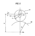
- the lens LE is rotated by drive of the motor 120 so that the geometric center FC of the target lens shape, the optical center OC of the lens LE, and the rotation center 166C of the roughing grindstone 166 (center of the grindstone spindle 161a) are positioned on a straight line (on the Y-axis).
- the lens chuck shafts 102R and 102L are moved in the Y-axis direction to bring the lens LE into contact with the roughing grindstone 166.
- control portion 50 compares a drive pulse signal of the motor 150 with a pulse signal output from the encoder 150a, and when a deviation in which the value is equal to or more than a predetermined value occurs between the both signals, the control portion 50 detects that the lens LE is in a state of being brought into contact with the roughing grindstone 166.
- the control portion 50 determines a radius rL which is an outer diameter of the lens LE according to the following equation, based on an axis-to-axis distance La between the centers (geometric centers FC of the target lens shape) of the lens chuck shafts 102R and 102L at this time and the center 166C of the grindstone spindle 161a, a distance Lb between the geometric center FC and the optical center OC of the lens LE, and a radius RC of the roughing grindstone 166.
- rL La - Lb - RC
- the axis-to-axis distance La is obtained based on the pulse signal from the encoder 150a when it is detected that the lens LE is in contact with the roughing grindstone 166.
- the distance Lb is determined from the FPD value, the PD value of layout data first input, and height data of the optical center OC relative to the geometric center FC of the target lens shape.
- the radius RC of the roughing grindstone 166 is a known value in terms of design, and stored in the memory 51.
- the geometric center FC is the lens chuck center.
- the measurement of the outer diameter of the lens LE is preferably performed while the rotation of the roughing grindstone 166 is stopped However, to shorten the processing time, the measurement may be performed while the roughing grindstone 166 is rotated in order to continuously perform the roughing. In this case, since the roughing grindstone 166 is rotated, a contacted portion of the lens LE is slightly ground. However, the grinding amount is a maximum of about 1 mm, and thus, the radius rL of the lens LE can be approximately obtained. With respect to management of a cutting amount described next, when a grinding amount at the time of measuring the lens outer diameter is estimated, there occurs only a small practical problem. A member to be contacted at the time of measuring the lens outer diameter includes not only the roughing grindstone 166 but also another grindstone attached to the grindstone spindle 161 a.
- the lens edge position measurement portion 200F or 200R may also be used as means for measuring the outer diameter of the unprocessed lens LE.
- the control portion 50 rotates the lens LE so that a straight line connecting the optical center OC and the geometric center FC of the target lens shape is positioned on the Y-axis, and thereafter, brings the measurement portion 206F of the lens edge position measurement portion 200F (or the measurement portion 206R of the lens edge position measurement portion 200R) into contact with an area above the target lens shape FT.
- the control portion 50 controls the Y-axis movement of the lens LE so that the measurement portion 206F moves toward the outer periphery of the lens,
- the measurement portion 206F deviates from a state of contacting a refractive surface of the lens LE
- detection information of the edge position of the encoder 213F rapidly changes.
- the radius rL which is an outer diameter of the prior-to-be-processed lens LE can be calculated.
- the operator may input this diameter on a predetermined input screen of the display 5 so as to obtain the outer diameter.
- the process Upon completion of the obtaining step of the lens outer diameter, the process is then moved to a roughing step.
- Control of roughing in the soft processing mode in order to reduce the axial deviation of the lens LE at the time of roughing as a result of adoption of the up-cut system is described by using Fig. 7 and Fig. 8 .
- the control portion 50 controls an axis-to-axis distance L of the lens chuck shafts 102R and 102L and the grindstone spindle 161 a or a rotation speed of the lens LE (lens chuck shaft) so that a torque T ⁇ applied to the lens chuck shafts 102R and 102L falls below a predetermined threshold value T ⁇ s.
- the control portion 50 changes the axis-to-axis distance L so as to decrease a cutting amount D so that the torque T ⁇ falls below the threshold value T ⁇ s.
- the control portion 50 controls a change of the axis-to-axis distance L so that the cutting amount D reaches a preset cutting setting amount dn.
- the torque T ⁇ is detected by the control portion 50 based on a difference between a rotation command signal (command pulse) to the motor 120 and a detection signal (output pulse) of an actual rotating angle by the encoder 120a.
- the threshold value T ⁇ s in the soft processing mode is set as a value (low value in which an allowance is provided relative to a limit torque T ⁇ r when the axial deviation is generated) that can sufficiently suppress the generation of the axial deviation, and stored in the memory 51.
- the threshold value T ⁇ s in the soft processing mode is 1.5 Nm (newton meters), and is a value lower than a threshold value T ⁇ N (for example, 2.6 Nm) in the normal processing mode described later.
- the cutting setting amount dn in the soft processing mode is ser so that the roughing grindstone 166 is not deeply cut even when the torque T ⁇ falls below the threshold value T ⁇ s.
- the cutting amount D is large (the roughing grindstone 166 bites deeply into the lens LE)
- the force for pulling the lens LE to the grindstone 166 as indicated by the arrow FB in Fig. 1B increases, and the torque T ⁇ applied to the lens LE also tends to rapidly increase.
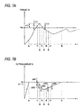
- Fig. 7A and Fig. 7B are graphs each showing a relationship between a change of the torque T ⁇ and a change of the cutting amount D.
- Fig. 7A shows a chronological change of the torque T ⁇
- Fig. 7B shows a chronological change of the cutting amount D
- the control portion 50 moves the lens chuck shafts 102R and 101 to the roughing grindstone 166 side while the lens LE is not allowed to rotate. If the torque T ⁇ detected by the encoder 120a falls below the threshold value T ⁇ s when the cutting amount D reaches the cutting setting amount dn, the control portion 50 rotates the lens LE in the same direction as the rotating direction of the roughing grindstone 166 (up cut). It is noted that the rotation speed of the lens LE is to be rotated at a constant speed.
- the control portion 50 rotates the lens LE, and at the same time, advances the axis-to-axis distance L by the cutting setting amount dn while the torque T ⁇ falls below the threshold value T ⁇ s. Thereafter, as shown in Fig. 7A , when the torque T ⁇ exceeds the threshold value T ⁇ s by ⁇ T1 at a time t1, at a time t2 at which the lens LE is rotated by a subsequent predetermined angle ⁇ , the control portion 50 controls the axis-to-axis distance L to allow the lens LE to retract by an amount ⁇ W1 according to ⁇ T1, relative to the cutting setting amount dn, as shown in Fig. 7B .
- the control portion 50 further controls the axis-to-axis distance L so as to allow the lens LE to retract by ⁇ W2 (two times ⁇ W1) according to ⁇ T2.
- the control portion 50 When the torque T ⁇ at a subsequent time t3 exceeds by ⁇ T3 (half ⁇ T1) relative to the threshold value T ⁇ s, the control portion 50 further controls the axis-to-axis distance L at a subsequent time t4 so as to allow the lens LE to retract by ⁇ W3 (half ⁇ W1) according to ⁇ T3.
- the torque T ⁇ is changed to be decreased, and then, falls below the threshold value T ⁇ s. Thereby, a load applied to the lens LE is prevented, and thus, the axial deviation is prevented.
- the control portion 50 controls the axis-to-axis distance L so as to increase the cutting amount by a predetermined amount ⁇ W0 at a subsequent time t5.
- the control portion 50 pulse-rotates the Y-axis movement motor 150 at each five pulse rotations of the lens rotating motor 120 so as to gradually reduce the axis-to-axis distance L by each certain amount.
- the control portion 50 rotates the lens LE at a constant speed by each predetermined angle ⁇ , and controls the axis-to-axis distance L to.
- the control portion 50 controls to obtain the axis-to-axis distance L of the cutting setting amount dn.
- control portion 50 controls the axis-to-axis distance L so that the torque T ⁇ stays under the threshold value T ⁇ s, and when the torque T ⁇ falls below the threshold value T ⁇ s, the control portion 50 controls the axis-to-axis distance L so that the cutting amount D stays under the cutting setting amount dn.
- the cutting setting amount dn may be constant irrespective of the number of rotations of the lens.
- the control portion 50 increases the cutting setting amount dn in conjunction with an increase in the number of rotations n of the lens LE.
- the cutting setting amount d1 of the first rotation is set to an amount by which no axial deviation is generated, where average diameter and lens thickness of the lens LE are used as a reference.
- the cutting setting amount d1 is set to 3 mm and ⁇ is set to 0.5 mm. Even when the lens thickness is thicker than the average thickness, by the change of the cutting amount by the axis-to-axis distance L based on the aforementioned detection result of the torque T ⁇ , the axial deviation can be suppressed.
- Fig. 8 is a diagram schematically showing a processing path of the lens LE by the above-described control.
- a dotted line N1 which is a next inner line from an outer circumference Ne of the lens LE indicates a path processed by a cutting setting amount d1 of the first rotation of the lens LE.
- the lens periphery is largely roughened as indicated by a shaded portion LC1.
- dotted line N2 which is a next inner line from the dotted line N1 indicates a path processed by the cutting setting amount d2 when the lens LE enters the second rotation.
- the path N2 of the second rotation is that which is obtained by shortening the axis-to-axis distance L by the cutting setting amount d2 when an outer diameter after one rotation of the lens LE is used as a reference.
- the processed outer diameter after one rotation of the lens LE can be determined by storing the axis-to-axis distance L controlled by each rotating angle ⁇ n of the lens LE in the memory 51.
- the processed outer diameter is cut and ground largely by an retracting amount ( ⁇ W1, ⁇ W2, etc.) relative to the path N2.
- a path of the third rotation of the lens LE is that which is obtained by shortening the axis-to-axis distance L by a cutting setting amount d3 when the processed outer diameter is used as a reference.
- the roughing of the fourth rotation and onward are similarly processed.
- the lens periphery is roughened in a shape in which a margin amount of finishing processing, done by bevel grindstone, etc., is left relative to the target lens shape FT.
- the thus roughened outer diameter of the lens periphery is preferably used as a reference.
- this, process requires a time for arithmetic process of the control portion 50.
- the cutting setting amount dn is set by providing an allowance for the axial deviation, in the second rotation of the lens LE, the cutting setting amount d2 may be adopted by using the path N1 as a reference.
- the preset path is similarly used as a reference, and controlled by the cutting setting amount.
- the axial deviation in conjunction with the up-cut processing can be suppressed. Further, due to the fact that the up-cut system is adopted, the generation of a large processing noise can be suppressed.
- the control portion 50 rotates the lens LE at a constant rotation speed v (speed preset so that no axial deviation is generated) while controlling the axis-to-axis distance L by the cutting setting amount dn, and when the torque T ⁇ exceeds the threshold value T ⁇ s, the control portion 50 controls the rotation speed of the lens chuck shafts 102R and 102L so as to decelerate the rotation speed of the lens LE according to the difference ( ⁇ T).
- the control portion 50 gradually accelerates the rotation speed until the rotation speed v is achieved, Thereby, roughing in which the axial deviation is prevented is performed.
- the normal processing mode when the normal processing mode is selected, the processing time can be shortened while suppressing the generation of the axial deviation.
- the normal processing mode the up-cut system in which the lens LE is rotated in the same direction as that of the roughing grindstone 166 is performed.
- a value of a threshold value T ⁇ N when the axis-to-axis distance L (or the rotation speed of the lens LE) is changed by the detection of the torque T ⁇ is set high.
- the threshold value T ⁇ s in the soft mode is 1.5 Nm while the threshold value T ⁇ N in the normal processing mode is set to 2.6 Nm.
- the cutting setting amount dn in the normal processing mode is set larger than in the soft mode.
- the cutting setting amount d1 in the soft mode is 3 mm while the cutting setting amount d1 in the normal processing mode is set to 5 mm.
- the lens chuck shafts 102R and 102L are moved in the X-axis direction and the Y-axis direction, and finishing processing is performed based on the target lens shape data by the finishing grindstone 163 or 164.
- the finishing processing is beveling and plane edging, and these are processed according to a well-known method, and thus, the description is omitted.
Landscapes
- Engineering & Computer Science (AREA)
- Mechanical Engineering (AREA)
- Chemical & Material Sciences (AREA)
- Ceramic Engineering (AREA)
- Inorganic Chemistry (AREA)
- Grinding And Polishing Of Tertiary Curved Surfaces And Surfaces With Complex Shapes (AREA)
- Constituent Portions Of Griding Lathes, Driving, Sensing And Control (AREA)
Applications Claiming Priority (1)
| Application Number | Priority Date | Filing Date | Title |
|---|---|---|---|
| JP2007316344A JP5301823B2 (ja) | 2007-12-06 | 2007-12-06 | 眼鏡レンズ周縁加工装置 |
Publications (3)
| Publication Number | Publication Date |
|---|---|
| EP2067572A2 true EP2067572A2 (de) | 2009-06-10 |
| EP2067572A3 EP2067572A3 (de) | 2013-04-17 |
| EP2067572B1 EP2067572B1 (de) | 2014-04-16 |
Family
ID=40427932
Family Applications (1)
| Application Number | Title | Priority Date | Filing Date |
|---|---|---|---|
| EP08021118.8A Active EP2067572B1 (de) | 2007-12-06 | 2008-12-04 | Vorrichtung zum Bearbeiten von Brillengläsern |
Country Status (4)
| Country | Link |
|---|---|
| US (1) | US8333636B2 (de) |
| EP (1) | EP2067572B1 (de) |
| JP (1) | JP5301823B2 (de) |
| KR (1) | KR101516432B1 (de) |
Cited By (3)
| Publication number | Priority date | Publication date | Assignee | Title |
|---|---|---|---|---|
| EP2216133A1 (de) * | 2009-02-04 | 2010-08-11 | Nidek Co., Ltd. | Vorrichtung zum Bearbeiten von Brillengläsern |
| EP2505306A1 (de) * | 2011-03-30 | 2012-10-03 | Nidek Co., Ltd. | Vorrichtung zum Bearbeiten der Peripherie von Brillengläsern |
| CN112454073A (zh) * | 2020-12-08 | 2021-03-09 | 黄文强 | 一种多焦点儿童眼镜加工装置 |
Families Citing this family (8)
| Publication number | Priority date | Publication date | Assignee | Title |
|---|---|---|---|---|
| JP5469476B2 (ja) | 2010-02-15 | 2014-04-16 | 株式会社ニデック | 眼鏡レンズ加工装置 |
| JP5976270B2 (ja) * | 2010-09-30 | 2016-08-23 | 株式会社ニデック | 眼鏡レンズ加工装置 |
| BR112013008209B1 (pt) * | 2010-10-04 | 2022-03-15 | Schneider Gmbh & Co. Kg | Dispositivo para trabalhar uma lente óptica, lente óptica e processo para trabalhar uma lente óptica |
| FR2980387B1 (fr) * | 2011-09-26 | 2013-09-27 | Essilor Int | Procede de detourage d'une lentille ophtalmique |
| JP5899978B2 (ja) | 2012-02-03 | 2016-04-06 | 株式会社ニデック | 眼鏡レンズ加工装置 |
| KR101394231B1 (ko) * | 2012-09-27 | 2014-05-15 | 주식회사 휴비츠 | 안경 렌즈 가공 방법 |
| JP6236787B2 (ja) * | 2013-01-17 | 2017-11-29 | 株式会社ニデック | 眼鏡レンズ加工装置 |
| JP6510374B2 (ja) * | 2015-09-16 | 2019-05-08 | 光洋機械工業株式会社 | ワークの平面研削方法及び平面研削盤 |
Citations (6)
| Publication number | Priority date | Publication date | Assignee | Title |
|---|---|---|---|---|
| JPH0493164A (ja) | 1990-08-09 | 1992-03-25 | Nidek Co Ltd | 眼鏡レンズ研削加工機 |
| US5333412A (en) | 1990-08-09 | 1994-08-02 | Nidek Co., Ltd. | Apparatus for and method of obtaining processing information for fitting lenses in eyeglasses frame and eyeglasses grinding machine |
| US20030087584A1 (en) | 2001-11-08 | 2003-05-08 | Nidek Co., Ltd. | Eyeglass lens processing apparatus |
| JP2004025561A (ja) | 2002-06-24 | 2004-01-29 | Kitsuta Seisan Kogyosho:Kk | 自動車のパワーステアリング油圧ポンプ用樹脂製貯油タンクの製造方法 |
| US20040192170A1 (en) | 2003-02-05 | 2004-09-30 | Nidek Co., Ltd. | Eyeglass lens processing apparatus |
| JP2006334701A (ja) | 2005-05-31 | 2006-12-14 | Nidek Co Ltd | 眼鏡レンズ加工装置 |
Family Cites Families (7)
| Publication number | Priority date | Publication date | Assignee | Title |
|---|---|---|---|---|
| DE19914174A1 (de) | 1999-03-29 | 2000-10-12 | Wernicke & Co Gmbh | Verfahren und Vorrichtung zum Formbearbeiten des Umfangsrandes von Brillengläsern |
| CN101092024A (zh) * | 2000-04-28 | 2007-12-26 | 3M创新有限公司 | 研磨制品以及研磨玻璃的方法 |
| JP2003340698A (ja) * | 2002-05-30 | 2003-12-02 | Hoya Corp | レンズ加工装置及びレンズ加工方法 |
| JP2005125491A (ja) * | 2004-12-21 | 2005-05-19 | Topcon Corp | レンズ周縁加工装置及びレンズ周縁加工方法 |
| JP4290673B2 (ja) * | 2005-04-28 | 2009-07-08 | 株式会社ニデック | 眼鏡レンズ周縁加工方法 |
| JP2007152439A (ja) * | 2005-11-30 | 2007-06-21 | Nidek Co Ltd | 眼鏡レンズ加工装置 |
| US8390240B2 (en) * | 2007-08-06 | 2013-03-05 | GM Global Technology Operations LLC | Absolute position sensor for field-oriented control of an induction motor |
-
2007
- 2007-12-06 JP JP2007316344A patent/JP5301823B2/ja active Active
-
2008
- 2008-12-03 KR KR1020080121715A patent/KR101516432B1/ko active Active
- 2008-12-04 EP EP08021118.8A patent/EP2067572B1/de active Active
- 2008-12-08 US US12/329,916 patent/US8333636B2/en active Active
Patent Citations (7)
| Publication number | Priority date | Publication date | Assignee | Title |
|---|---|---|---|---|
| JPH0493164A (ja) | 1990-08-09 | 1992-03-25 | Nidek Co Ltd | 眼鏡レンズ研削加工機 |
| US5333412A (en) | 1990-08-09 | 1994-08-02 | Nidek Co., Ltd. | Apparatus for and method of obtaining processing information for fitting lenses in eyeglasses frame and eyeglasses grinding machine |
| US20030087584A1 (en) | 2001-11-08 | 2003-05-08 | Nidek Co., Ltd. | Eyeglass lens processing apparatus |
| JP2003145328A (ja) | 2001-11-08 | 2003-05-20 | Nidek Co Ltd | 眼鏡レンズ加工装置 |
| JP2004025561A (ja) | 2002-06-24 | 2004-01-29 | Kitsuta Seisan Kogyosho:Kk | 自動車のパワーステアリング油圧ポンプ用樹脂製貯油タンクの製造方法 |
| US20040192170A1 (en) | 2003-02-05 | 2004-09-30 | Nidek Co., Ltd. | Eyeglass lens processing apparatus |
| JP2006334701A (ja) | 2005-05-31 | 2006-12-14 | Nidek Co Ltd | 眼鏡レンズ加工装置 |
Cited By (6)
| Publication number | Priority date | Publication date | Assignee | Title |
|---|---|---|---|---|
| EP2216133A1 (de) * | 2009-02-04 | 2010-08-11 | Nidek Co., Ltd. | Vorrichtung zum Bearbeiten von Brillengläsern |
| US8241091B2 (en) | 2009-02-04 | 2012-08-14 | Nidek Co., Ltd. | Eyeglass lens processing apparatus |
| EP2505306A1 (de) * | 2011-03-30 | 2012-10-03 | Nidek Co., Ltd. | Vorrichtung zum Bearbeiten der Peripherie von Brillengläsern |
| US10046434B2 (en) | 2011-03-30 | 2018-08-14 | Nidek Co., Ltd. | Eyeglass lens periphery processing apparatus |
| CN112454073A (zh) * | 2020-12-08 | 2021-03-09 | 黄文强 | 一种多焦点儿童眼镜加工装置 |
| CN112454073B (zh) * | 2020-12-08 | 2022-05-13 | 南京灵雀智能制造有限公司 | 一种多焦点儿童眼镜加工装置 |
Also Published As
| Publication number | Publication date |
|---|---|
| JP5301823B2 (ja) | 2013-09-25 |
| US8333636B2 (en) | 2012-12-18 |
| KR20090060164A (ko) | 2009-06-11 |
| KR101516432B1 (ko) | 2015-05-04 |
| US20090176442A1 (en) | 2009-07-09 |
| EP2067572B1 (de) | 2014-04-16 |
| EP2067572A3 (de) | 2013-04-17 |
| JP2009136969A (ja) | 2009-06-25 |
Similar Documents
| Publication | Publication Date | Title |
|---|---|---|
| EP2067572B1 (de) | Vorrichtung zum Bearbeiten von Brillengläsern | |
| EP2065129B1 (de) | Vorrichtung zum Bearbeiten von Brillengläsern | |
| US6719609B2 (en) | Eyeglass lens processing apparatus | |
| EP1815941B1 (de) | Vorrichtung zum Bearbeiten von Brillengläsern | |
| JP3730410B2 (ja) | 眼鏡レンズ加工装置 | |
| JP5302029B2 (ja) | 眼鏡レンズ加工装置 | |
| EP1510290B1 (de) | Vorrichtung zum Bearbeiten von Brillengläsern | |
| EP1445065A1 (de) | Brillenglas-Bearbeitungsvorrichtung | |
| JP5976270B2 (ja) | 眼鏡レンズ加工装置 | |
| JP4429211B2 (ja) | 眼鏡レンズ加工装置 | |
| US7220162B2 (en) | Eyeglass lens processing apparatus | |
| JP4368693B2 (ja) | レンズ研削加工方法及びその装置 | |
| JP6236787B2 (ja) | 眼鏡レンズ加工装置 | |
| JP4431413B2 (ja) | 眼鏡レンズ加工装置 | |
| JP3893081B2 (ja) | 眼鏡レンズ加工装置 | |
| JP4036931B2 (ja) | 眼鏡レンズ研削装置 | |
| JP4036942B2 (ja) | 眼鏡レンズ研削装置 |
Legal Events
| Date | Code | Title | Description |
|---|---|---|---|
| PUAI | Public reference made under article 153(3) epc to a published international application that has entered the european phase |
Free format text: ORIGINAL CODE: 0009012 |
|
| AK | Designated contracting states |
Kind code of ref document: A2 Designated state(s): AT BE BG CH CY CZ DE DK EE ES FI FR GB GR HR HU IE IS IT LI LT LU LV MC MT NL NO PL PT RO SE SI SK TR |
|
| AX | Request for extension of the european patent |
Extension state: AL BA MK RS |
|
| PUAL | Search report despatched |
Free format text: ORIGINAL CODE: 0009013 |
|
| AK | Designated contracting states |
Kind code of ref document: A3 Designated state(s): AT BE BG CH CY CZ DE DK EE ES FI FR GB GR HR HU IE IS IT LI LT LU LV MC MT NL NO PL PT RO SE SI SK TR |
|
| AX | Request for extension of the european patent |
Extension state: AL BA MK RS |
|
| RIC1 | Information provided on ipc code assigned before grant |
Ipc: B24B 49/16 20060101ALI20130308BHEP Ipc: B24B 9/14 20060101AFI20130308BHEP Ipc: B24B 49/10 20060101ALI20130308BHEP |
|
| 17P | Request for examination filed |
Effective date: 20131009 |
|
| RBV | Designated contracting states (corrected) |
Designated state(s): AT BE BG CH CY CZ DE DK EE ES FI FR GB GR HR HU IE IS IT LI LT LU LV MC MT NL NO PL PT RO SE SI SK TR |
|
| GRAP | Despatch of communication of intention to grant a patent |
Free format text: ORIGINAL CODE: EPIDOSNIGR1 |
|
| AKX | Designation fees paid |
Designated state(s): AT BE BG CH CY CZ DE DK EE ES FI FR GB GR HR HU IE IS IT LI LT LU LV MC MT NL NO PL PT RO SE SI SK TR |
|
| INTG | Intention to grant announced |
Effective date: 20131128 |
|
| GRAS | Grant fee paid |
Free format text: ORIGINAL CODE: EPIDOSNIGR3 |
|
| GRAA | (expected) grant |
Free format text: ORIGINAL CODE: 0009210 |
|
| AK | Designated contracting states |
Kind code of ref document: B1 Designated state(s): AT BE BG CH CY CZ DE DK EE ES FI FR GB GR HR HU IE IS IT LI LT LU LV MC MT NL NO PL PT RO SE SI SK TR |
|
| REG | Reference to a national code |
Ref country code: GB Ref legal event code: FG4D |
|
| REG | Reference to a national code |
Ref country code: CH Ref legal event code: EP |
|
| REG | Reference to a national code |
Ref country code: AT Ref legal event code: REF Ref document number: 662206 Country of ref document: AT Kind code of ref document: T Effective date: 20140515 |
|
| REG | Reference to a national code |
Ref country code: IE Ref legal event code: FG4D |
|
| REG | Reference to a national code |
Ref country code: DE Ref legal event code: R096 Ref document number: 602008031492 Country of ref document: DE Effective date: 20140528 |
|
| REG | Reference to a national code |
Ref country code: AT Ref legal event code: MK05 Ref document number: 662206 Country of ref document: AT Kind code of ref document: T Effective date: 20140416 |
|
| REG | Reference to a national code |
Ref country code: NL Ref legal event code: VDEP Effective date: 20140416 |
|
| REG | Reference to a national code |
Ref country code: LT Ref legal event code: MG4D |
|
| PG25 | Lapsed in a contracting state [announced via postgrant information from national office to epo] |
Ref country code: GR Free format text: LAPSE BECAUSE OF FAILURE TO SUBMIT A TRANSLATION OF THE DESCRIPTION OR TO PAY THE FEE WITHIN THE PRESCRIBED TIME-LIMIT Effective date: 20140717 Ref country code: IS Free format text: LAPSE BECAUSE OF FAILURE TO SUBMIT A TRANSLATION OF THE DESCRIPTION OR TO PAY THE FEE WITHIN THE PRESCRIBED TIME-LIMIT Effective date: 20140816 Ref country code: LT Free format text: LAPSE BECAUSE OF FAILURE TO SUBMIT A TRANSLATION OF THE DESCRIPTION OR TO PAY THE FEE WITHIN THE PRESCRIBED TIME-LIMIT Effective date: 20140416 Ref country code: BG Free format text: LAPSE BECAUSE OF FAILURE TO SUBMIT A TRANSLATION OF THE DESCRIPTION OR TO PAY THE FEE WITHIN THE PRESCRIBED TIME-LIMIT Effective date: 20140716 Ref country code: NL Free format text: LAPSE BECAUSE OF FAILURE TO SUBMIT A TRANSLATION OF THE DESCRIPTION OR TO PAY THE FEE WITHIN THE PRESCRIBED TIME-LIMIT Effective date: 20140416 Ref country code: FI Free format text: LAPSE BECAUSE OF FAILURE TO SUBMIT A TRANSLATION OF THE DESCRIPTION OR TO PAY THE FEE WITHIN THE PRESCRIBED TIME-LIMIT Effective date: 20140416 Ref country code: CY Free format text: LAPSE BECAUSE OF FAILURE TO SUBMIT A TRANSLATION OF THE DESCRIPTION OR TO PAY THE FEE WITHIN THE PRESCRIBED TIME-LIMIT Effective date: 20140416 Ref country code: NO Free format text: LAPSE BECAUSE OF FAILURE TO SUBMIT A TRANSLATION OF THE DESCRIPTION OR TO PAY THE FEE WITHIN THE PRESCRIBED TIME-LIMIT Effective date: 20140716 |
|
| PG25 | Lapsed in a contracting state [announced via postgrant information from national office to epo] |
Ref country code: ES Free format text: LAPSE BECAUSE OF FAILURE TO SUBMIT A TRANSLATION OF THE DESCRIPTION OR TO PAY THE FEE WITHIN THE PRESCRIBED TIME-LIMIT Effective date: 20140416 Ref country code: PL Free format text: LAPSE BECAUSE OF FAILURE TO SUBMIT A TRANSLATION OF THE DESCRIPTION OR TO PAY THE FEE WITHIN THE PRESCRIBED TIME-LIMIT Effective date: 20140416 Ref country code: SE Free format text: LAPSE BECAUSE OF FAILURE TO SUBMIT A TRANSLATION OF THE DESCRIPTION OR TO PAY THE FEE WITHIN THE PRESCRIBED TIME-LIMIT Effective date: 20140416 Ref country code: LV Free format text: LAPSE BECAUSE OF FAILURE TO SUBMIT A TRANSLATION OF THE DESCRIPTION OR TO PAY THE FEE WITHIN THE PRESCRIBED TIME-LIMIT Effective date: 20140416 Ref country code: AT Free format text: LAPSE BECAUSE OF FAILURE TO SUBMIT A TRANSLATION OF THE DESCRIPTION OR TO PAY THE FEE WITHIN THE PRESCRIBED TIME-LIMIT Effective date: 20140416 Ref country code: HR Free format text: LAPSE BECAUSE OF FAILURE TO SUBMIT A TRANSLATION OF THE DESCRIPTION OR TO PAY THE FEE WITHIN THE PRESCRIBED TIME-LIMIT Effective date: 20140416 |
|
| PG25 | Lapsed in a contracting state [announced via postgrant information from national office to epo] |
Ref country code: PT Free format text: LAPSE BECAUSE OF FAILURE TO SUBMIT A TRANSLATION OF THE DESCRIPTION OR TO PAY THE FEE WITHIN THE PRESCRIBED TIME-LIMIT Effective date: 20140818 |
|
| REG | Reference to a national code |
Ref country code: DE Ref legal event code: R097 Ref document number: 602008031492 Country of ref document: DE |
|
| PG25 | Lapsed in a contracting state [announced via postgrant information from national office to epo] |
Ref country code: BE Free format text: LAPSE BECAUSE OF FAILURE TO SUBMIT A TRANSLATION OF THE DESCRIPTION OR TO PAY THE FEE WITHIN THE PRESCRIBED TIME-LIMIT Effective date: 20140416 Ref country code: CZ Free format text: LAPSE BECAUSE OF FAILURE TO SUBMIT A TRANSLATION OF THE DESCRIPTION OR TO PAY THE FEE WITHIN THE PRESCRIBED TIME-LIMIT Effective date: 20140416 Ref country code: RO Free format text: LAPSE BECAUSE OF FAILURE TO SUBMIT A TRANSLATION OF THE DESCRIPTION OR TO PAY THE FEE WITHIN THE PRESCRIBED TIME-LIMIT Effective date: 20140416 Ref country code: EE Free format text: LAPSE BECAUSE OF FAILURE TO SUBMIT A TRANSLATION OF THE DESCRIPTION OR TO PAY THE FEE WITHIN THE PRESCRIBED TIME-LIMIT Effective date: 20140416 Ref country code: DK Free format text: LAPSE BECAUSE OF FAILURE TO SUBMIT A TRANSLATION OF THE DESCRIPTION OR TO PAY THE FEE WITHIN THE PRESCRIBED TIME-LIMIT Effective date: 20140416 Ref country code: SK Free format text: LAPSE BECAUSE OF FAILURE TO SUBMIT A TRANSLATION OF THE DESCRIPTION OR TO PAY THE FEE WITHIN THE PRESCRIBED TIME-LIMIT Effective date: 20140416 |
|
| PLBE | No opposition filed within time limit |
Free format text: ORIGINAL CODE: 0009261 |
|
| STAA | Information on the status of an ep patent application or granted ep patent |
Free format text: STATUS: NO OPPOSITION FILED WITHIN TIME LIMIT |
|
| 26N | No opposition filed |
Effective date: 20150119 |
|
| PG25 | Lapsed in a contracting state [announced via postgrant information from national office to epo] |
Ref country code: IT Free format text: LAPSE BECAUSE OF FAILURE TO SUBMIT A TRANSLATION OF THE DESCRIPTION OR TO PAY THE FEE WITHIN THE PRESCRIBED TIME-LIMIT Effective date: 20140416 |
|
| REG | Reference to a national code |
Ref country code: DE Ref legal event code: R097 Ref document number: 602008031492 Country of ref document: DE Effective date: 20150119 |
|
| PG25 | Lapsed in a contracting state [announced via postgrant information from national office to epo] |
Ref country code: LU Free format text: LAPSE BECAUSE OF FAILURE TO SUBMIT A TRANSLATION OF THE DESCRIPTION OR TO PAY THE FEE WITHIN THE PRESCRIBED TIME-LIMIT Effective date: 20141204 Ref country code: SI Free format text: LAPSE BECAUSE OF FAILURE TO SUBMIT A TRANSLATION OF THE DESCRIPTION OR TO PAY THE FEE WITHIN THE PRESCRIBED TIME-LIMIT Effective date: 20140416 |
|
| REG | Reference to a national code |
Ref country code: CH Ref legal event code: PL |
|
| REG | Reference to a national code |
Ref country code: IE Ref legal event code: MM4A |
|
| PG25 | Lapsed in a contracting state [announced via postgrant information from national office to epo] |
Ref country code: CH Free format text: LAPSE BECAUSE OF NON-PAYMENT OF DUE FEES Effective date: 20141231 Ref country code: IE Free format text: LAPSE BECAUSE OF NON-PAYMENT OF DUE FEES Effective date: 20141204 Ref country code: LI Free format text: LAPSE BECAUSE OF NON-PAYMENT OF DUE FEES Effective date: 20141231 |
|
| REG | Reference to a national code |
Ref country code: FR Ref legal event code: PLFP Year of fee payment: 8 |
|
| PG25 | Lapsed in a contracting state [announced via postgrant information from national office to epo] |
Ref country code: MC Free format text: LAPSE BECAUSE OF FAILURE TO SUBMIT A TRANSLATION OF THE DESCRIPTION OR TO PAY THE FEE WITHIN THE PRESCRIBED TIME-LIMIT Effective date: 20140416 |
|
| PG25 | Lapsed in a contracting state [announced via postgrant information from national office to epo] |
Ref country code: MT Free format text: LAPSE BECAUSE OF FAILURE TO SUBMIT A TRANSLATION OF THE DESCRIPTION OR TO PAY THE FEE WITHIN THE PRESCRIBED TIME-LIMIT Effective date: 20140416 Ref country code: HU Free format text: LAPSE BECAUSE OF FAILURE TO SUBMIT A TRANSLATION OF THE DESCRIPTION OR TO PAY THE FEE WITHIN THE PRESCRIBED TIME-LIMIT; INVALID AB INITIO Effective date: 20081204 Ref country code: TR Free format text: LAPSE BECAUSE OF FAILURE TO SUBMIT A TRANSLATION OF THE DESCRIPTION OR TO PAY THE FEE WITHIN THE PRESCRIBED TIME-LIMIT Effective date: 20140416 |
|
| REG | Reference to a national code |
Ref country code: FR Ref legal event code: PLFP Year of fee payment: 9 |
|
| REG | Reference to a national code |
Ref country code: FR Ref legal event code: PLFP Year of fee payment: 10 |
|
| PGFP | Annual fee paid to national office [announced via postgrant information from national office to epo] |
Ref country code: GB Payment date: 20211028 Year of fee payment: 14 Ref country code: DE Payment date: 20211102 Year of fee payment: 14 |
|
| P01 | Opt-out of the competence of the unified patent court (upc) registered |
Effective date: 20230509 |
|
| REG | Reference to a national code |
Ref country code: DE Ref legal event code: R119 Ref document number: 602008031492 Country of ref document: DE |
|
| GBPC | Gb: european patent ceased through non-payment of renewal fee |
Effective date: 20221204 |
|
| PG25 | Lapsed in a contracting state [announced via postgrant information from national office to epo] |
Ref country code: GB Free format text: LAPSE BECAUSE OF NON-PAYMENT OF DUE FEES Effective date: 20221204 Ref country code: DE Free format text: LAPSE BECAUSE OF NON-PAYMENT OF DUE FEES Effective date: 20230701 |
|
| PGFP | Annual fee paid to national office [announced via postgrant information from national office to epo] |
Ref country code: FR Payment date: 20241111 Year of fee payment: 17 |