EP2505306A1 - Vorrichtung zum Bearbeiten der Peripherie von Brillengläsern - Google Patents
Vorrichtung zum Bearbeiten der Peripherie von Brillengläsern Download PDFInfo
- Publication number
- EP2505306A1 EP2505306A1 EP12002265A EP12002265A EP2505306A1 EP 2505306 A1 EP2505306 A1 EP 2505306A1 EP 12002265 A EP12002265 A EP 12002265A EP 12002265 A EP12002265 A EP 12002265A EP 2505306 A1 EP2505306 A1 EP 2505306A1
- Authority
- EP
- European Patent Office
- Prior art keywords
- lens
- shape
- unit
- refractive surface
- held
- Prior art date
- Legal status (The legal status is an assumption and is not a legal conclusion. Google has not performed a legal analysis and makes no representation as to the accuracy of the status listed.)
- Granted
Links
- 230000003287 optical effect Effects 0.000 claims abstract description 49
- 238000001514 detection method Methods 0.000 description 71
- 238000000034 method Methods 0.000 description 22
- 238000010586 diagram Methods 0.000 description 17
- 238000012790 confirmation Methods 0.000 description 15
- 238000005259 measurement Methods 0.000 description 9
- 230000005540 biological transmission Effects 0.000 description 2
- 230000002146 bilateral effect Effects 0.000 description 1
- 239000000284 extract Substances 0.000 description 1
- 230000006870 function Effects 0.000 description 1
- 239000000463 material Substances 0.000 description 1
Images


Classifications
-
- B—PERFORMING OPERATIONS; TRANSPORTING
- B24—GRINDING; POLISHING
- B24B—MACHINES, DEVICES, OR PROCESSES FOR GRINDING OR POLISHING; DRESSING OR CONDITIONING OF ABRADING SURFACES; FEEDING OF GRINDING, POLISHING, OR LAPPING AGENTS
- B24B49/00—Measuring or gauging equipment for controlling the feed movement of the grinding tool or work; Arrangements of indicating or measuring equipment, e.g. for indicating the start of the grinding operation
- B24B49/10—Measuring or gauging equipment for controlling the feed movement of the grinding tool or work; Arrangements of indicating or measuring equipment, e.g. for indicating the start of the grinding operation involving electrical means
-
- B—PERFORMING OPERATIONS; TRANSPORTING
- B24—GRINDING; POLISHING
- B24B—MACHINES, DEVICES, OR PROCESSES FOR GRINDING OR POLISHING; DRESSING OR CONDITIONING OF ABRADING SURFACES; FEEDING OF GRINDING, POLISHING, OR LAPPING AGENTS
- B24B51/00—Arrangements for automatic control of a series of individual steps in grinding a workpiece
-
- B—PERFORMING OPERATIONS; TRANSPORTING
- B24—GRINDING; POLISHING
- B24B—MACHINES, DEVICES, OR PROCESSES FOR GRINDING OR POLISHING; DRESSING OR CONDITIONING OF ABRADING SURFACES; FEEDING OF GRINDING, POLISHING, OR LAPPING AGENTS
- B24B9/00—Machines or devices designed for grinding edges or bevels on work or for removing burrs; Accessories therefor
- B24B9/02—Machines or devices designed for grinding edges or bevels on work or for removing burrs; Accessories therefor characterised by a special design with respect to properties of materials specific to articles to be ground
- B24B9/06—Machines or devices designed for grinding edges or bevels on work or for removing burrs; Accessories therefor characterised by a special design with respect to properties of materials specific to articles to be ground of non-metallic inorganic material, e.g. stone, ceramics, porcelain
- B24B9/08—Machines or devices designed for grinding edges or bevels on work or for removing burrs; Accessories therefor characterised by a special design with respect to properties of materials specific to articles to be ground of non-metallic inorganic material, e.g. stone, ceramics, porcelain of glass
- B24B9/14—Machines or devices designed for grinding edges or bevels on work or for removing burrs; Accessories therefor characterised by a special design with respect to properties of materials specific to articles to be ground of non-metallic inorganic material, e.g. stone, ceramics, porcelain of glass of optical work, e.g. lenses, prisms
- B24B9/148—Machines or devices designed for grinding edges or bevels on work or for removing burrs; Accessories therefor characterised by a special design with respect to properties of materials specific to articles to be ground of non-metallic inorganic material, e.g. stone, ceramics, porcelain of glass of optical work, e.g. lenses, prisms electrically, e.g. numerically, controlled
Definitions
- the present invention relates to an eyeglass lens periphery processing apparatus that processes a periphery of an eyeglass lens.
- the eyeglass lens periphery processing apparatus holds an eyeglass lens by a lens chuck shaft, and processes the periphery of the lens by a periphery processing tool such as a grindstone while rotating the lens based on a target lens shape.
- the target lens shapes are different between the left side (left lens) and the right side (right lens), and optical center positions of the lens relative to the target lens shape are different between the left lens and the right lens. For this reason, a worker needs to hold the lens in the chuck shaft without confusing the left side and the right side of the lens at the time of setting (a selection) of the left side and the right side of lens processing conditions that are input to the apparatus.
- JP-A-2008-105151 and JP-A-2008-137106 are used, a problem of the selection mistake between the left side and the right side of the lens is reduced, but a further improvement is desired.
- the selection mistake between the left side and the right side of the lens is generated in the case of performing the periphery processing of blank lenses based on the target lens shape, and in addition, the selection mistake is easily generated in the case of a so-called "retouching" which performs a size adjustment processing for reducing the size of the processed lens.
- An object of the present invention is to provide an eyeglass lens periphery processing apparatus that is able to reduce the selection mistake between the left side and the right side of the lens when performing the periphery processing of the lens.
- An aspect of the present invention provides the following arrangements:
- Fig. 1 is a schematic configuration diagram of an eyeglass lens periphery processing apparatus.
- a carriage 101 which rotatably holds a pair of lens chuck shafts 102L and 102R is mounted on a base 170 of the processing apparatus 1.
- a periphery of an eyeglass lens LE held between the chuck shafts 102L and 102R is processed while being pressed against the respective grindstones of a grindstone group 168 as a processing tool which is concentrically attached to a spindle (a processing tool rotation shaft) 161a.
- the grindstone group 168 includes a coarse grindstone 162, and a finishing grindstone 164 with a V groove and a flat processing surface for forming a bevel.
- a processing tool rotation unit is constituted by the components.
- a cutter may be used as the processing tool.
- the lens chuck shaft 102R is moved to the lens chuck shaft 102L side by a motor 110 attached to a right arm 101R of the carriage 101. Furthermore, the lens chuck shafts 102R and 102L are synchronously rotated by a motor 120 attached to a left arm 101L via a rotation transmission mechanism such as a gear.
- An encoder 121 which detects rotation angles of the lens chuck shafts 102R and 102L, is attached to the rotation shaft of the motor 120. In addition, it is possible to detect the load torque applied to the lens chuck shafts 102R and 102L during processing by the encoder 121.
- the lens rotation unit is constituted by the components.
- the carriage 101 is mounted on a support base 140 which is movable along shafts 103 and 104 extended in an X axis direction (an axial direction of the chuck shaft), and is moved in the X axis direction by the driving of a motor 145.
- An encoder 146 which detects a movement position of the carriage 101 (the chuck shafts 102R and 102L) in the X axis direction, is attached to the rotation shaft of the motor 145.
- An X axis moving unit is constituted by these components.
- shafts 156 and 157 extended in a Y axis direction (a direction in which an inter-axis distance between the chuck shafts 102L and 102R and a grindstone spindle 161a fluctuates) is fixed to the support based 140.
- the carriage 101 is mounted on the support base 140 so as to be movable along the shafts 156 and 157 in the Y axis direction.
- a Y axis moving motor 150 is fixed to the support base 140. The rotation of the motor 150 is transmitted to a ball screw 155 extended in the Y axis direction, and the carriage 101 is moved in the Y axis direction by the rotation of the ball screw 155.
- An encoder 158 which detects the movement position of the lens chuck shaft in the Y axis direction, is attached to the rotation shaft of the motor 150.
- a Y axis moving unit (an inter-axis distance variation unit) is constituted by these components.
- Fig. 1 in the left and right sides of the upper part of the carriage 101, lens edge position detection units 300F and 300R as a first les shape detection unit (a lens refractive surface shape detection unit) are provided.
- Fig. 2 is a schematic configuration diagram of the detection unit 300F which detects an edge position (an edge position of the lens front refractive surface side on the target lens shape) of the lens front refractive surface.
- a support base 301F is fixed to a block 300a fixed on the base 170.
- a tracing stylus arm 304F is held so as to slidable in the X axis direction via the slide base 310F.
- An L type hand 305F is fixed to the tip portion of the tracing stylus arm 304F, and a tracing stylus 306F is fixed to the tip of the hand 305F.
- the tracing stylus 306F comes into contact with the front refractive surface of the lens LE.
- a rack 311F is fixed to a lower end portion of the slide base 310F.
- the rack 311F is meshed with a pinion 312F of an encoder 313F fixed to the support base 310F side.
- the rotation of the motor 316F is transmitted to the rack 311F via a rotation transmission mechanism such as gears 315F and 314F, and the slide base 310F is moved in the X axis direction.
- the tracing stylus 306F situated in a retracted position is moved to the lens LE side by the movement of the motor 316F, and measurement force is applied which presses the tracing stylus 306F against the lens LE.
- the lens chuck shafts 102L and 102R are moved in the Y axis direction while the lens LE is rotated based on the target lens shape, and the edge position (the lens front refractive surface edge of the target lens shape) of the lens front refractive surface in the X axis direction is detected over the whole periphery of the lens by the encoder 313F.
- the edge position detection is preferably performed by a measurement trace of the outside (for example, 1mm outside) of the target lens shape by a predetermined amount, in addition to the measurement trace of the target lens shape. With the edge position detection through two measurement traces, a slope of the lens refractive surface in the edge position of the target lens shape is obtained.
- a configuration of the edge position detection unit 300R of the lens rear refractive surface is bilateral symmetry of the detection unit 300F, and thus, "F" of ends of the reference numerals attached to the respective components of the detection unit 300F shown in Fig. 2 is replaced with “R”, and the descriptions thereof will be omitted.
- a lens outer diameter detection unit 500 as a second lens shape detection unit is placed behind the upside of the lens chuck shaft 102R.
- Fig. 3 is a schematic configuration diagram of the lens outer diameter detection unit 500.
- a cylindrical tracing stylus 520 coming into contact with the edge (the periphery) of the lens LE is fixed to an end of the arm 501, and a rotation shaft 502 is fixed to the other end of the arm 501.
- a cylindrical portion 521a comes into contact with the periphery of the lens LE.
- a center axis 520a of the tracing stylus 520 and a center axis 502a of the rotation shaft 502 are placed in a position relationship parallel to the lens chuck shafts 102L and 102R (the X axis direction).
- the rotation shaft 502 is held in the holding portion 503 so as to be rotatable around the center axis 502a.
- the holding portion 503 is fixed to the block 300a of Fig. 1 .
- the rotation shaft 502 is rotated by the motor 510 via the gear 505 and the pinion gear 512.
- an encoder 511 is attached to the rotation shaft of the motor 510.
- the rotation amount of the tracing stylus 520 around the center axis 502a is detected by the encoder 511, and the outer diameter of the lens LE is detected from the detected rotation amount.
- the lens chuck shafts 102L and 102R are moved to a predetermined measurement position (on a movement trace 530 of the center axis 520a of the tracing stylus 520 rotated around the rotation shaft 502).
- the arm 501 is rotated to a direction (the Z axis direction) perpendicular to the X axis and the Y axis of the processing apparatus 1 by the motor 510, whereby the tracing stylus 520 placed in the retracted position is moved to the lens LE side, and the cylindrical portion 521a of the tracing stylus 520 comes into contact with the edge (the outer periphery) of the lens LE.
- a predetermined measurement force is applied to the tracing stylus 520 by the motor 510.
- the lens LE is rotated for each predetermined minute angle step, and the movement of the tracing stylus 520 of this time is detected by the encoder 511, whereby the outer diameter size of the lens LE based on the chuck center (the processing center, and the rotation center) is measured.
- the lens outer diameter detection unit 500 is constituted by a rotation mechanism of the arm 501 as mentioned above, and in addition, the lens outer diameter detection unit 500 may be a mechanism which is linearly moved in a direction perpendicular to the X axis and the Y axis of the processing apparatus 1. Furthermore, the lens edge position detection unit 300F (or 300R) can also be used as the lens outer diameter detection unit. In this case, the lens chuck shafts 102L and 102R are moved in the Y axis direction so as to move the tracing stylus 306F to the lens outer diameter side in the state of bringing the tracing stylus 306F into contact with the lens front refractive surface.
- the detection value of the encoder 313F is rapidly changed, and thus, it is possible to detect the outer diameter of the lens LE from the movement distance of the Y axis direction of this time.
- Fig. 5 is a control block diagram of the eyeglass lens processing apparatus.
- the control unit 50 performs the integrated control of the entire apparatus, and performs the calculation processing based on each measurement data and input data.
- Each motor of the apparatus 1, the lens edge position detection units 300F and 300R, and the lens outer diameter detection unit 500 are connected to the control unit 50.
- a display 60 having a touch panel function for data input of the processing condition
- a switch portion 70 having various switches
- a memory 51 an eyeglass frame shape measuring device 2 or the like
- the switch portion 70 is provided with a switch which starts the processing of the lens LE.
- the target lens shape data of the lens frame (a rim) of the eyeglass frame obtained by the measurement of the eyeglass frame shape measuring device 2 is input to the processing apparatus 1 by the operation of the switch of the switch portion 70, and is stored in the memory 51.
- Each target lens shape data of a right lens frame and a left lens frame is input or one target lens shape data of the left and the right is input from the eyeglass frame shape measuring device 2.
- the control unit 50 obtains the other target lens shape data by inverting the left and the right of the input target lens shape data.
- Fig. 5 shows an example of the setting screen which is displayed on the display 60 so as to set the processing condition.
- a switch 61 is displayed which selects (sets) which one is the left or the right of the processing target lens. Whenever the switch 61 is touched, "R" and “L” of the display of the switch 61 is switched, and it is selected which one is the left side or the right side (left lens or right lens) of the lens.
- a target lens shape figure FT is displayed on the display 60, based on the target lens shape data called from the memory 51.
- the layout data of the optical center OC of the left lens with respect to the geometric center FC of the left target lens shape is input, and the layout data of the optical center OC of the right lens with respect to the geometric center FC of the right target lens shape is input.
- a geometric center distance (a FPD value) of the left and right lens frames is input to an input box 62a.
- a pupil-to-pupil distance (a PD value) of a wearer is input to an input box 62b.
- a height of the right optical center OC with respect to the geometric center FC of the right target lens shape is input to an input box 62cR.
- a height of the left optical center OC with respect to the geometric center FC of the left target lens shape is input to an input box 62cL.
- the numerical values of each input box can be input by a numeric keypad which is displayed by touching the input boxes.
- the processing conditions such as a material of the lens, a type of the frame, working modes (a bevel processing mode, and a flat processing mode), and presence or absence of the chamfering processing by the switches 63a, 63b, 63c, and 63d.
- an operator fixes a cup Cu, which is a fixing jig, to the lens refractive surface of the lens LE by the use of a known axis stoker.
- a cup Cu which is a fixing jig
- a frame center mode which fixes the cup to the geometric center FC of the target lens shape.
- the chuck center (the processing center) of the lens chuck shafts 102L and 102R is which one of the optical center mode and the frame center mode by the right lower switch 65 of the screen of the display 60.
- a switch 66 is provided which sets "retouching" that is the size adjusting processing for reducing the outer diameter of the processed lens.
- the lens outer diameter detection unit 500 is operated by the control unit 50, and the outer diameter of the lens LE is detected around the lens chuck shaft.
- the outer diameter of the lens LE it is confirmed whether or not the outer diameter of the lens LE is insufficient for the target lens shape. In a case where the outer diameter of the lens LE is insufficient, the warning is displayed on the display 60.
- the lens edge position detection units 300F and 300R are driven by the control unit 50, and the shapes of the front refractive surface and the rear refractive surface of the lens LE in the edge position of the target lens shape are detected.
- the lens thickness in the edge position of the target lens shape is obtained from the shapes of the detected front refractive surface and rear refractive surface.
- the bevel trace which is the trace of the placement of the bevel apex, is obtained by a predetermined calculation based on the edge position detection information of the front refractive surface and the rear refractive surface of the lens.
- the roughing trace is calculated based on the input target lens shape, and the periphery of the lens LE is processed along the roughing trace by the coarse grindstone 162.
- the roughing trace is calculated by adding the finishing allowance to the target lens shape.
- the control unit 50 obtains the roughing control data of the rotation angles of the lens chuck shafts 102L and 102R and the movement of the lens chuck shafts 102L and 102R in the Y axis direction, based on the roughing trace, and roughs the periphery of the lens LE by the coarse grindstone 162.
- control unit 50 obtains the finishing control data of the rotation angles of the lens chuck shafts 102L and 102R and the movement of the lens chuck shafts 102L and 102R in the Y axis direction, based on the finishing trace (the bevel trace), and finishes the periphery of the lens LE by the finishing grindstone 164.
- the left and right confirmation operation includes a method of using the detection result of the lens outer diameter detection unit 500, and a method of using the detection result of the lens edge position detection units 300F and 300R.
- the lens LE is a blank lens
- the frame center mode (a mode in which the geometric center FC of the target lens shape is the chuck center) is set.
- the lens outer diameter detection unit 500 is operated by the signal input of the start switch, and the outer diameter of the lens LE centered on the lens chuck shaft is detected.
- the control unit 50 confirms that there is no mistake in the left and right of the lens LE held in the lens chuck shafts 102L and 102R (the lens LE is the left lens or the right lens), based on the detection result of the lens outer diameter detection unit 500, the layout data (position relationship data between the chuck center and the optical center OC of the lens LE) which is input by the display 60, and the left and right selection data of the lens LE which is set by the switch 61.
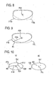
- Fig. 6 is an explanatory diagram of the left and right confirmation which uses the detection result of the lens outer diameter, and is a case where the right lens is selected by the switch 61 and the target lens shape for the right lens is called from the memory 51.
- the target lens shape FTR is set for the right lens by the selection of the right lens
- the FCR is the geometric center of the target lens shape FTR.
- the geometric center FCR is the chuck center of the lens chuck shaft in the frame center mode.
- the OCR shows the optical center position of the lens LE determined by the input of the layout data for the right lens.
- the circle CER is an example of the lens outer diameter trace detected by the lens outer diameter detection unit 500 when the right lens is correctly held in the lens chuck shaft. Or shows the geometric center of the circle CER, and in the case of the blank lens, Or is calculated to the optical center position of the right lens LE.
- the control unit 50 compares the optical center position OCR due to the layout data to the optical center position Or, and obtains the amount of deviation.
- the eccentricity ⁇ xr may be obtained. If the eccentricity ⁇ xr does not exceed a predetermined allowable value S (for example, 1 mm) and the position OCR substantially coincides with the position Or, it is confirmed (determined) that the lens LE held in the lens chuck shaft is the right lens as set by the switch 61. If there is no mistake in the left and right confirmation of the lens LE, the processing of the lens periphery through the coarse grindstone 162 and the finishing grindstone 164 is performed. In order to notify the confirmation result of the left and right sides of the lens LE to an operator, a configuration may be adopted in which the confirmation result is displayed on the display 60.
- the circle CEL is an example of the lens outer diameter trace detected by the lens outer diameter detection unit 500 when the left lens is incorrectly held in the lens chuck shaft.
- Ol indicates the geometric center of the circle CER and is calculated to be the optical center position of the left lens.
- the control unit 50 compares the optical center position OCR due to the layout data to the optical center position Ol, and obtains the amount of deviation ⁇ xl of the horizontal direction.
- the eccentricity ⁇ xl exceeds a predetermined allowable value S, the lens LE held in the lens chuck shaft is the left lens, and it is confirmed (determined) that the setting of the right lens through the switch 61 is wrong.
- the warning that the left and right sides of the lens LE are wrong is displayed on the display 60, and the mistake of the left and right sides of the lens LE is notified to an operator. Furthermore, the processing operation of the lens periphery after that is stopped.
- the display 60 is used as the warning device which warns the mistake of the left and right sides of the lens.
- a buzzer generating the warning sound may be provided.
- An operator can notice that the left and right sides of the lens held in the lens chuck shaft are wrong, by the warning of the display 60 or the stop of the processing operation of the device, and can correct the error. As a result, it is possible to prevent the periphery being processed in the state where the left and right sides are wrong, whereby it is possible to suppress the occurrence of the lens being unusable.
- the above situation is a case where the right lens is selected by the switch 61, but in a case where the left lens is selected, by simply reversing the left and right sides, the left and right confirmation is basically performed by the same method.
- the optical center position Or (Ol) of the lens LE is obtained by the use of the detection result of the lens outer diameter, and it is also possible to use the lens edge position detection units 300F and 300R (the lens refractive surface shape measurement unit).
- the lens edge position detection units 300F and 300R the lens refractive surface shape measurement unit.
- Fig. 7 is an explanatory diagram of a case of obtaining the optical center from the refractive surface shape of the lens.
- the control unit 50 obtains the curve spherical surface of the lens refractive surface and the center position Sfo of the curve spherical surface by a predetermined calculation, based on the detection result of the target lens shape lens front refractive surface edge position Lpf through the control unit 300F. For example, by selecting arbitrary four points from the lens front refractive surface edge position Lpf of the lens whole periphery and obtaining the radius Sf of the spherical surface when the four points are situated on the spherical surface, the center position Sfo of the spherical surface can be obtained.
- the position can be obtained as below.
- the slope angle of the straight line Lf (not shown) passing through the two points of the target lens shape lens front refractive surface edge position Lpf and the lens front refractive edge position outside from that by a predetermined amount for each minute vectorial angle of the target lens shape is obtained, and based on the slope angle of the straight line Lf in the plurality of edge positions Lpf of the lens entire periphery, the radius Sf of the spherical surface of the lens front refractive surface and the center position Sfo can be optically obtained.
- the radius Sf of the spherical surface of the lens rear refractive surface and the center position Sro thereof can also be obtained by the same calculation based on the detection result of the lens rear refractive surface edge position Lpr.
- the lens rear refractive surface is a toric surface, but the center position Sro is obtained by obtaining the toric surface as an averaged spherical surface.
- the straight line connecting the center position Sfo with the center position Sro is obtained, and the point, on which the straight line intersects with the curve spherical surface of the lens rear refractive surface, can be approximately calculated as the optical center Or.
- the optical center Or is obtained as the position data with respect to the chuck center FCR of the lens chuck shaft. In Fig. 7 , the center FCR is situated on the axis XI of the lens chuck shaft.
- the position data of the optical center Or with respect to the chuck center FCR is obtained, like a case of Fig. 6 which uses the lens outer diameter detection, the left and right sides of the lens LE held in the lens chuck shafts 102L and 102R are confirmed, based on the layout data which is input by the switch 60, and the left and right selection data of the lens LE which is set by the switch 61.
- the processing mode of the eyeglass lens processing device is shifted to the retouching mode.
- the screen of Fig. 5 is switched to the retouching screen for inputting processing condition data required for the retouching such as the size adjusting data (not shown).
- the switch 61 for selecting the left and right sides of the lens LE attached to the lens chuck shaft is provided.
- the left and right confirmation of the lens LE also includes a method of using the lens outer diameter detection unit 500 and a method of using the lens edge position detection units 300F and 300R. Firstly, the method of using the lens outer diameter detection unit 500 will be described.
- the lens outer diameter detection unit 500 is operated by the control unit 50.
- the right lens of the lenses LE is selected by the selection switch 61.
- Fig. 8 is an explanatory diagram of the outer diameter trace of the processed lens which is detected by the lens outer diameter detection unit 500.
- the outer diameter trace FTRa is a trace of a case where the processed lens is the right lens as selected by the selection switch 61.
- the control unit 50 compares the trace FTRa obtained by the lens outer diameter detection unit 500 to the right target lens shape data used in the periphery processing before the retouching, and confirms whether or hot both of them substantially coincide with each other.
- the right target lens shape data is stored and held in the memory 51 and is called by the selection of the right lens through the selection switch 61.
- the control unit 50 determines that there is no mistake in the left and right sides of the processed lens attached to the lens chuck shaft, moves the lens chuck shafts 102R and 102R to the XY direction based on the size adjustment data which is input by the retouching screen and the right target lens shape data, and performs the finishing processing by the finishing grindstone 164.
- the trace FTRb in Fig. 8 is a trace detected by the lens outer diameter detection unit 500.
- the control portion 70 compares the trace FTRb with the right target lens shape data. When both of them do not substantially coincide with each other, the control portion 70 determines that the left and right sides of the processed lens attached to the lens chuck shaft are wrong, and displays the warning on the screen of the display 60. Furthermore, the control unit 50 stops the processing operation. As a result, a worker is notified that the left and right sides of the lens are wrong.
- the method of comparing the trace FTRa (FTRb) to the right target lens shape (the left target lens shape) determined by the left and right selection information can be also applied to the "optical center mode" which holds the optical center of the lens LE.
- the control unit 50 calls the data of the right target lens shape FTR and the left target lens shape FTL stored in the memory 51, and compares both of them.
- the control unit 50 extracts the different points of the target lens shape radius between the right target lens shape FTR and the left target lens shape FTL, and determines the position of the lens refractive surface with which the tracing stylus 306F (or 306R) of the lens edge position detection unit 300F (or 300R) comes into contact, based on the left and right selection information.
- the control unit 50 obtains the vectorial angle ⁇ pa in which the target lens shape radius of the right target lens shape FTR is greatly different from the left target lens shape FTL, and defines the point Pa somewhat inside (for example, 0.5 mm) from the edge position of the vectorial angle ⁇ pa of the right target lens shape FTR as the contact position.
- the lens edge position detection unit 300F is operated, and the tracing stylus 306F is brought into contact with the lens refractive surface based on the vectorial angle ⁇ pa of the point Pa and the vectorial length (the radius). If the right lens is correctly attached to the lens chuck shafts 102L and 102R, the tracing stylus 306F comes into contact with the lens refractive surface, and thus the contact is detected from the output signal of the encoder 313F.
- the tracing stylus 306F When the left lens is attached to the lens chuck shafts 102L and 102R, the tracing stylus 306F does not come into contact with the lens refractive surface, and it is detected that there is no lens. Whether or not the tracing stylus 306F comes into contact with the lens refractive surface is obtained from the detection of the encoder 313F.
- the detection data of the edge position of the right lens and the left lens before the retouching is stored in the memory 51. If the detected edge position greatly deviates from the edge position data of the vectorial angle ⁇ pa of the right lens stored in the memory 51, the lens LE held in the lens chuck shaft is confirmed (determined) as the left lens.
- This method is a method of confirming the left and right sides of the lens even in the left and right symmetrical target lens shape, based on the fact that the thickness of the edge position is different between the left lens and the right lens.
- the control unit 50 calls the edge position data of the selected lens from the memory 51 based on the left and right selection information, and obtains the edge thickness of the whole periphery of the target lens shape. Based on the edge thickness data, the position is determined with which the respective tracing styluses 306F and 306R of the lens edge position detection units 300F and 300R are brought into contact. As the position with which the tracing styluses 306F and 306R are brought into contact, if the position is a point in which the edge positions are different between the left lens and the right lens, one point may be satisfactory. However, a point is preferable in which the difference in the lens between the left lens and the right lens thickness easily appears.
- Fig. 10(a) is a case where the right lens is selected.
- any one (or both) of a point Pb1 of the vectorial angle ⁇ b1 in which the radius from the optical center OCR is the minimum and a point Pb2 of the vectorial angle ⁇ b2, in which the radius from the optical center OCR is the maximum, is used.
- the optical center OCR is the position defined by the layout data and substantially coincides with the actual optical center of the lens.
- the point Pb1 and the point Pb2 is defined as a point somewhat inside (for example, 0.5 mm) from the edge position.
- the control unit 50 brings the tracing styluses 306F and 306R into contact with the lens front refractive surface and the lens rear refractive surface of the point Pb1, and obtains the respective positions.
- the lens thickness of the point Pb1 is obtained from the respective edge positions.
- the control unit 50 calls the edge positions of the lens front refractive surface and the lens rear refractive surface obtained at the time of measuring the blank lens before the retouching from the memory 51, compares the edge position to the edge thickness (the edge thickness of the point Pb1) in the retouching mode, and if both of them substantially coincide with each other, the lens LE is determined as right lens.
- the lens LE held in the lens shuck shaft is the left lens, as shown in Fig. 10 (b) , since the distance from the optical center OCL of the left lens to the point Pb1 is different from the right lens, the edge thickness also differs. Thus, when the difference in the edge thickness exceeds a predetermined allowance amount in the comparison, the lens LE held in the lens chuck shaft is determined as the left lens and is warned by the display 60. Even when the point Pb2 is used, the same determination is performed. If both of the point Pb1 and the point Pb2 is used, an accuracy of determination of the left and right lenses is improved.
- any one of the lens outer diameter detection unit 500 and the lens edge position detection units 300F and 300R may be used, but when using a combination of both, the accuracy of the left and right confirmation is further improved.
Landscapes
- Engineering & Computer Science (AREA)
- Mechanical Engineering (AREA)
- Chemical & Material Sciences (AREA)
- Ceramic Engineering (AREA)
- Inorganic Chemistry (AREA)
- Grinding And Polishing Of Tertiary Curved Surfaces And Surfaces With Complex Shapes (AREA)
Applications Claiming Priority (1)
| Application Number | Priority Date | Filing Date | Title |
|---|---|---|---|
| JP2011076896A JP5745909B2 (ja) | 2011-03-30 | 2011-03-30 | 眼鏡レンズ周縁加工装置 |
Publications (2)
| Publication Number | Publication Date |
|---|---|
| EP2505306A1 true EP2505306A1 (de) | 2012-10-03 |
| EP2505306B1 EP2505306B1 (de) | 2013-10-23 |
Family
ID=46044144
Family Applications (1)
| Application Number | Title | Priority Date | Filing Date |
|---|---|---|---|
| EP12002265.2A Active EP2505306B1 (de) | 2011-03-30 | 2012-03-29 | Vorrichtung zum Bearbeiten der Peripherie von Brillengläsern |
Country Status (3)
| Country | Link |
|---|---|
| US (1) | US10046434B2 (de) |
| EP (1) | EP2505306B1 (de) |
| JP (1) | JP5745909B2 (de) |
Cited By (1)
| Publication number | Priority date | Publication date | Assignee | Title |
|---|---|---|---|---|
| EP3800007B1 (de) * | 2019-10-03 | 2024-02-28 | Nidek Co., Ltd. | System zur verarbeitung des aussenrandes eines brillenglases und programm zur verarbeitung des aussenrandes eines brillenglases |
Families Citing this family (6)
| Publication number | Priority date | Publication date | Assignee | Title |
|---|---|---|---|---|
| JP6236786B2 (ja) * | 2013-01-17 | 2017-11-29 | 株式会社ニデック | 眼鏡レンズ加工装置 |
| JP6197406B2 (ja) * | 2013-06-28 | 2017-09-20 | 株式会社ニデック | 眼鏡レンズ加工装置、眼鏡レンズ加工プログラム |
| JP6766400B2 (ja) * | 2016-03-28 | 2020-10-14 | 株式会社ニデック | 眼鏡レンズ加工装置、及び眼鏡レンズ加工プログラム |
| CN111482817A (zh) * | 2018-08-18 | 2020-08-04 | 章梦月 | 建筑钢筋材料两端的自动抛光倒角装置 |
| US10842189B1 (en) | 2019-10-09 | 2020-11-24 | Cegnum LLC | Electronic smoking device including terminals arranged to provide for selective energizing of heating elements |
| US10721973B1 (en) | 2019-10-09 | 2020-07-28 | Cegnum LLC | Electronic smoking device with an indicator assembly for providing visual output based on operation of plural atomizers |
Citations (6)
| Publication number | Priority date | Publication date | Assignee | Title |
|---|---|---|---|---|
| EP0235021A2 (de) * | 1986-02-10 | 1987-09-02 | Kabushiki Kaisha TOPCON | Linsenschleifvorrichtung |
| EP1155775A2 (de) * | 2000-04-28 | 2001-11-21 | Nidek Co., Ltd. | Brillenglas bearbeitungsvorrichtung |
| EP1366857A1 (de) * | 2002-05-28 | 2003-12-03 | Nidek Co., Ltd. | Vorrichtung zum Bearbeiten von Brillengläsern |
| JP2008105151A (ja) | 2006-10-26 | 2008-05-08 | Nidek Co Ltd | レンズ固定用カップ、カップ取付け装置及び眼鏡レンズ加工装置 |
| JP2008137106A (ja) | 2006-11-30 | 2008-06-19 | Nidek Co Ltd | 眼鏡レンズ加工システム |
| EP2067572A2 (de) * | 2007-12-06 | 2009-06-10 | Nidek Co., Ltd. | Vorrichtung zum Bearbeiten von Brillengläsern |
Family Cites Families (14)
| Publication number | Priority date | Publication date | Assignee | Title |
|---|---|---|---|---|
| JP2937366B2 (ja) * | 1989-11-07 | 1999-08-23 | 株式会社トプコン | 玉摺機 |
| DE69334004T2 (de) * | 1992-06-24 | 2006-10-19 | Hoya Corp. | Herstellung von Brillenlinsen |
| JP4011134B2 (ja) * | 1996-03-26 | 2007-11-21 | 株式会社ニデック | レンズ研削加工装置 |
| JP4034842B2 (ja) * | 1996-03-26 | 2008-01-16 | 株式会社ニデック | レンズ研削加工装置 |
| JP3667483B2 (ja) * | 1997-02-10 | 2005-07-06 | 株式会社ニデック | レンズ研削加工装置 |
| JP4087526B2 (ja) * | 1999-03-08 | 2008-05-21 | 株式会社トプコン | 眼鏡レンズのヤゲン形状表示装置及びその表示装置によるレンズ周縁加工方法及びそのレンズ周縁加工装置 |
| JP3839185B2 (ja) | 1999-04-30 | 2006-11-01 | 株式会社ニデック | 眼鏡レンズ加工装置 |
| JP3740326B2 (ja) * | 1999-08-06 | 2006-02-01 | Hoya株式会社 | 眼鏡レンズ加工方法及び眼鏡レンズ並びに眼鏡レンズ加工装置 |
| JP4121696B2 (ja) * | 2000-10-17 | 2008-07-23 | 株式会社トプコン | 眼鏡レンズの面取加工データ作成方法、眼鏡レンズの面取加工方法、眼鏡レンズの面取加工データ作成装置及び眼鏡レンズの面取加工装置 |
| JP3990104B2 (ja) * | 2000-10-17 | 2007-10-10 | 株式会社ニデック | レンズ研削加工装置 |
| US7151854B2 (en) * | 2001-09-06 | 2006-12-19 | Digimarc Corporation | Pattern recognition of objects in image streams |
| CN1965261B (zh) * | 2004-03-31 | 2010-06-16 | 株式会社拓普康 | 眼镜片的吸附夹具安装装置、以及吸附夹具安装位置决定方法 |
| FR2926898B1 (fr) * | 2008-01-28 | 2010-03-19 | Essilor Int | Procede de preparation d'une lentille ophtalmique avec un usinage specifique de sa nervure d'emboitement |
| JP5356082B2 (ja) * | 2009-03-26 | 2013-12-04 | 株式会社ニデック | 眼鏡レンズ加工装置 |
-
2011
- 2011-03-30 JP JP2011076896A patent/JP5745909B2/ja active Active
-
2012
- 2012-03-29 EP EP12002265.2A patent/EP2505306B1/de active Active
- 2012-03-30 US US13/435,609 patent/US10046434B2/en active Active
Patent Citations (6)
| Publication number | Priority date | Publication date | Assignee | Title |
|---|---|---|---|---|
| EP0235021A2 (de) * | 1986-02-10 | 1987-09-02 | Kabushiki Kaisha TOPCON | Linsenschleifvorrichtung |
| EP1155775A2 (de) * | 2000-04-28 | 2001-11-21 | Nidek Co., Ltd. | Brillenglas bearbeitungsvorrichtung |
| EP1366857A1 (de) * | 2002-05-28 | 2003-12-03 | Nidek Co., Ltd. | Vorrichtung zum Bearbeiten von Brillengläsern |
| JP2008105151A (ja) | 2006-10-26 | 2008-05-08 | Nidek Co Ltd | レンズ固定用カップ、カップ取付け装置及び眼鏡レンズ加工装置 |
| JP2008137106A (ja) | 2006-11-30 | 2008-06-19 | Nidek Co Ltd | 眼鏡レンズ加工システム |
| EP2067572A2 (de) * | 2007-12-06 | 2009-06-10 | Nidek Co., Ltd. | Vorrichtung zum Bearbeiten von Brillengläsern |
Cited By (1)
| Publication number | Priority date | Publication date | Assignee | Title |
|---|---|---|---|---|
| EP3800007B1 (de) * | 2019-10-03 | 2024-02-28 | Nidek Co., Ltd. | System zur verarbeitung des aussenrandes eines brillenglases und programm zur verarbeitung des aussenrandes eines brillenglases |
Also Published As
| Publication number | Publication date |
|---|---|
| JP2012210667A (ja) | 2012-11-01 |
| US20120252315A1 (en) | 2012-10-04 |
| US10046434B2 (en) | 2018-08-14 |
| EP2505306B1 (de) | 2013-10-23 |
| JP5745909B2 (ja) | 2015-07-08 |
Similar Documents
| Publication | Publication Date | Title |
|---|---|---|
| EP2505306B1 (de) | Vorrichtung zum Bearbeiten der Peripherie von Brillengläsern | |
| EP2191935B1 (de) | Brillenglasverarbeitungsvorrichtung zur Verarbeitung der Peripherie eines Brillenglases | |
| US8235770B2 (en) | Eyeglass lens processing apparatus | |
| US8506352B2 (en) | Eyeglass lens processing apparatus | |
| JP4772342B2 (ja) | 眼鏡レンズ加工装置 | |
| US7410408B2 (en) | Eyeglass lens processing apparatus | |
| KR101848092B1 (ko) | 안경 렌즈 가공 장치 | |
| US8157618B2 (en) | Eyeglass lens processing apparatus | |
| US7220162B2 (en) | Eyeglass lens processing apparatus | |
| US9475242B2 (en) | Eyeglass lens processing apparatus | |
| KR20080072583A (ko) | 안경 렌즈 가공 장치 | |
| EP2529885A2 (de) | Vorrichtung zum Bearbeiten von Brillengläsern | |
| JP6187743B2 (ja) | 眼鏡レンズ加工装置 | |
| JP6236787B2 (ja) | 眼鏡レンズ加工装置 | |
| JP5578549B2 (ja) | 眼鏡レンズ加工装置 | |
| JP6439361B2 (ja) | ヤゲン又は溝の形成データ設定装置、及びヤゲン又は溝の形成データ設定プログラム | |
| JP3893081B2 (ja) | 眼鏡レンズ加工装置 | |
| US20230311266A1 (en) | Non-transitory computer-readable storage medium, method of managing eyeglasses lens machining apparatus, and eyeglasses lens machining apparatus |
Legal Events
| Date | Code | Title | Description |
|---|---|---|---|
| PUAI | Public reference made under article 153(3) epc to a published international application that has entered the european phase |
Free format text: ORIGINAL CODE: 0009012 |
|
| AK | Designated contracting states |
Kind code of ref document: A1 Designated state(s): AL AT BE BG CH CY CZ DE DK EE ES FI FR GB GR HR HU IE IS IT LI LT LU LV MC MK MT NL NO PL PT RO RS SE SI SK SM TR |
|
| AX | Request for extension of the european patent |
Extension state: BA ME |
|
| 17P | Request for examination filed |
Effective date: 20130328 |
|
| GRAP | Despatch of communication of intention to grant a patent |
Free format text: ORIGINAL CODE: EPIDOSNIGR1 |
|
| RIC1 | Information provided on ipc code assigned before grant |
Ipc: B24B 49/10 20060101ALI20130423BHEP Ipc: B24B 51/00 20060101ALI20130423BHEP Ipc: B24B 9/14 20060101AFI20130423BHEP Ipc: B24B 49/00 20120101ALI20130423BHEP |
|
| INTG | Intention to grant announced |
Effective date: 20130522 |
|
| GRAS | Grant fee paid |
Free format text: ORIGINAL CODE: EPIDOSNIGR3 |
|
| GRAA | (expected) grant |
Free format text: ORIGINAL CODE: 0009210 |
|
| AK | Designated contracting states |
Kind code of ref document: B1 Designated state(s): AL AT BE BG CH CY CZ DE DK EE ES FI FR GB GR HR HU IE IS IT LI LT LU LV MC MK MT NL NO PL PT RO RS SE SI SK SM TR |
|
| REG | Reference to a national code |
Ref country code: GB Ref legal event code: FG4D |
|
| REG | Reference to a national code |
Ref country code: CH Ref legal event code: EP |
|
| REG | Reference to a national code |
Ref country code: AT Ref legal event code: REF Ref document number: 637264 Country of ref document: AT Kind code of ref document: T Effective date: 20131115 |
|
| REG | Reference to a national code |
Ref country code: IE Ref legal event code: FG4D |
|
| REG | Reference to a national code |
Ref country code: DE Ref legal event code: R096 Ref document number: 602012000405 Country of ref document: DE Effective date: 20131219 |
|
| REG | Reference to a national code |
Ref country code: NL Ref legal event code: VDEP Effective date: 20131023 |
|
| REG | Reference to a national code |
Ref country code: AT Ref legal event code: MK05 Ref document number: 637264 Country of ref document: AT Kind code of ref document: T Effective date: 20131023 |
|
| REG | Reference to a national code |
Ref country code: LT Ref legal event code: MG4D |
|
| PG25 | Lapsed in a contracting state [announced via postgrant information from national office to epo] |
Ref country code: IS Free format text: LAPSE BECAUSE OF FAILURE TO SUBMIT A TRANSLATION OF THE DESCRIPTION OR TO PAY THE FEE WITHIN THE PRESCRIBED TIME-LIMIT Effective date: 20140223 Ref country code: SE Free format text: LAPSE BECAUSE OF FAILURE TO SUBMIT A TRANSLATION OF THE DESCRIPTION OR TO PAY THE FEE WITHIN THE PRESCRIBED TIME-LIMIT Effective date: 20131023 Ref country code: HR Free format text: LAPSE BECAUSE OF FAILURE TO SUBMIT A TRANSLATION OF THE DESCRIPTION OR TO PAY THE FEE WITHIN THE PRESCRIBED TIME-LIMIT Effective date: 20131023 Ref country code: NO Free format text: LAPSE BECAUSE OF FAILURE TO SUBMIT A TRANSLATION OF THE DESCRIPTION OR TO PAY THE FEE WITHIN THE PRESCRIBED TIME-LIMIT Effective date: 20140123 Ref country code: BE Free format text: LAPSE BECAUSE OF FAILURE TO SUBMIT A TRANSLATION OF THE DESCRIPTION OR TO PAY THE FEE WITHIN THE PRESCRIBED TIME-LIMIT Effective date: 20131023 Ref country code: LT Free format text: LAPSE BECAUSE OF FAILURE TO SUBMIT A TRANSLATION OF THE DESCRIPTION OR TO PAY THE FEE WITHIN THE PRESCRIBED TIME-LIMIT Effective date: 20131023 Ref country code: FI Free format text: LAPSE BECAUSE OF FAILURE TO SUBMIT A TRANSLATION OF THE DESCRIPTION OR TO PAY THE FEE WITHIN THE PRESCRIBED TIME-LIMIT Effective date: 20131023 Ref country code: NL Free format text: LAPSE BECAUSE OF FAILURE TO SUBMIT A TRANSLATION OF THE DESCRIPTION OR TO PAY THE FEE WITHIN THE PRESCRIBED TIME-LIMIT Effective date: 20131023 |
|
| PG25 | Lapsed in a contracting state [announced via postgrant information from national office to epo] |
Ref country code: ES Free format text: LAPSE BECAUSE OF FAILURE TO SUBMIT A TRANSLATION OF THE DESCRIPTION OR TO PAY THE FEE WITHIN THE PRESCRIBED TIME-LIMIT Effective date: 20131023 Ref country code: AT Free format text: LAPSE BECAUSE OF FAILURE TO SUBMIT A TRANSLATION OF THE DESCRIPTION OR TO PAY THE FEE WITHIN THE PRESCRIBED TIME-LIMIT Effective date: 20131023 Ref country code: RS Free format text: LAPSE BECAUSE OF FAILURE TO SUBMIT A TRANSLATION OF THE DESCRIPTION OR TO PAY THE FEE WITHIN THE PRESCRIBED TIME-LIMIT Effective date: 20131023 Ref country code: LV Free format text: LAPSE BECAUSE OF FAILURE TO SUBMIT A TRANSLATION OF THE DESCRIPTION OR TO PAY THE FEE WITHIN THE PRESCRIBED TIME-LIMIT Effective date: 20131023 Ref country code: CY Free format text: LAPSE BECAUSE OF FAILURE TO SUBMIT A TRANSLATION OF THE DESCRIPTION OR TO PAY THE FEE WITHIN THE PRESCRIBED TIME-LIMIT Effective date: 20131023 |
|
| PG25 | Lapsed in a contracting state [announced via postgrant information from national office to epo] |
Ref country code: PT Free format text: LAPSE BECAUSE OF FAILURE TO SUBMIT A TRANSLATION OF THE DESCRIPTION OR TO PAY THE FEE WITHIN THE PRESCRIBED TIME-LIMIT Effective date: 20140224 |
|
| REG | Reference to a national code |
Ref country code: DE Ref legal event code: R097 Ref document number: 602012000405 Country of ref document: DE |
|
| PG25 | Lapsed in a contracting state [announced via postgrant information from national office to epo] |
Ref country code: EE Free format text: LAPSE BECAUSE OF FAILURE TO SUBMIT A TRANSLATION OF THE DESCRIPTION OR TO PAY THE FEE WITHIN THE PRESCRIBED TIME-LIMIT Effective date: 20131023 |
|
| PG25 | Lapsed in a contracting state [announced via postgrant information from national office to epo] |
Ref country code: SK Free format text: LAPSE BECAUSE OF FAILURE TO SUBMIT A TRANSLATION OF THE DESCRIPTION OR TO PAY THE FEE WITHIN THE PRESCRIBED TIME-LIMIT Effective date: 20131023 Ref country code: CZ Free format text: LAPSE BECAUSE OF FAILURE TO SUBMIT A TRANSLATION OF THE DESCRIPTION OR TO PAY THE FEE WITHIN THE PRESCRIBED TIME-LIMIT Effective date: 20131023 Ref country code: IT Free format text: LAPSE BECAUSE OF FAILURE TO SUBMIT A TRANSLATION OF THE DESCRIPTION OR TO PAY THE FEE WITHIN THE PRESCRIBED TIME-LIMIT Effective date: 20131023 Ref country code: RO Free format text: LAPSE BECAUSE OF FAILURE TO SUBMIT A TRANSLATION OF THE DESCRIPTION OR TO PAY THE FEE WITHIN THE PRESCRIBED TIME-LIMIT Effective date: 20131023 Ref country code: PL Free format text: LAPSE BECAUSE OF FAILURE TO SUBMIT A TRANSLATION OF THE DESCRIPTION OR TO PAY THE FEE WITHIN THE PRESCRIBED TIME-LIMIT Effective date: 20131023 |
|
| PLBE | No opposition filed within time limit |
Free format text: ORIGINAL CODE: 0009261 |
|
| STAA | Information on the status of an ep patent application or granted ep patent |
Free format text: STATUS: NO OPPOSITION FILED WITHIN TIME LIMIT |
|
| PG25 | Lapsed in a contracting state [announced via postgrant information from national office to epo] |
Ref country code: DK Free format text: LAPSE BECAUSE OF FAILURE TO SUBMIT A TRANSLATION OF THE DESCRIPTION OR TO PAY THE FEE WITHIN THE PRESCRIBED TIME-LIMIT Effective date: 20131023 |
|
| 26N | No opposition filed |
Effective date: 20140724 |
|
| PG25 | Lapsed in a contracting state [announced via postgrant information from national office to epo] |
Ref country code: LU Free format text: LAPSE BECAUSE OF FAILURE TO SUBMIT A TRANSLATION OF THE DESCRIPTION OR TO PAY THE FEE WITHIN THE PRESCRIBED TIME-LIMIT Effective date: 20140329 |
|
| REG | Reference to a national code |
Ref country code: DE Ref legal event code: R097 Ref document number: 602012000405 Country of ref document: DE Effective date: 20140724 |
|
| REG | Reference to a national code |
Ref country code: IE Ref legal event code: MM4A |
|
| PG25 | Lapsed in a contracting state [announced via postgrant information from national office to epo] |
Ref country code: IE Free format text: LAPSE BECAUSE OF NON-PAYMENT OF DUE FEES Effective date: 20140329 |
|
| PG25 | Lapsed in a contracting state [announced via postgrant information from national office to epo] |
Ref country code: SI Free format text: LAPSE BECAUSE OF FAILURE TO SUBMIT A TRANSLATION OF THE DESCRIPTION OR TO PAY THE FEE WITHIN THE PRESCRIBED TIME-LIMIT Effective date: 20131023 |
|
| REG | Reference to a national code |
Ref country code: CH Ref legal event code: PL |
|
| PG25 | Lapsed in a contracting state [announced via postgrant information from national office to epo] |
Ref country code: LI Free format text: LAPSE BECAUSE OF NON-PAYMENT OF DUE FEES Effective date: 20150331 Ref country code: CH Free format text: LAPSE BECAUSE OF NON-PAYMENT OF DUE FEES Effective date: 20150331 |
|
| REG | Reference to a national code |
Ref country code: FR Ref legal event code: PLFP Year of fee payment: 5 |
|
| PG25 | Lapsed in a contracting state [announced via postgrant information from national office to epo] |
Ref country code: MT Free format text: LAPSE BECAUSE OF FAILURE TO SUBMIT A TRANSLATION OF THE DESCRIPTION OR TO PAY THE FEE WITHIN THE PRESCRIBED TIME-LIMIT Effective date: 20131023 |
|
| PG25 | Lapsed in a contracting state [announced via postgrant information from national office to epo] |
Ref country code: SM Free format text: LAPSE BECAUSE OF FAILURE TO SUBMIT A TRANSLATION OF THE DESCRIPTION OR TO PAY THE FEE WITHIN THE PRESCRIBED TIME-LIMIT Effective date: 20131023 |
|
| PG25 | Lapsed in a contracting state [announced via postgrant information from national office to epo] |
Ref country code: MC Free format text: LAPSE BECAUSE OF FAILURE TO SUBMIT A TRANSLATION OF THE DESCRIPTION OR TO PAY THE FEE WITHIN THE PRESCRIBED TIME-LIMIT Effective date: 20131023 |
|
| PG25 | Lapsed in a contracting state [announced via postgrant information from national office to epo] |
Ref country code: BG Free format text: LAPSE BECAUSE OF FAILURE TO SUBMIT A TRANSLATION OF THE DESCRIPTION OR TO PAY THE FEE WITHIN THE PRESCRIBED TIME-LIMIT Effective date: 20131023 Ref country code: GR Free format text: LAPSE BECAUSE OF FAILURE TO SUBMIT A TRANSLATION OF THE DESCRIPTION OR TO PAY THE FEE WITHIN THE PRESCRIBED TIME-LIMIT Effective date: 20140124 |
|
| PG25 | Lapsed in a contracting state [announced via postgrant information from national office to epo] |
Ref country code: HU Free format text: LAPSE BECAUSE OF FAILURE TO SUBMIT A TRANSLATION OF THE DESCRIPTION OR TO PAY THE FEE WITHIN THE PRESCRIBED TIME-LIMIT; INVALID AB INITIO Effective date: 20120329 Ref country code: TR Free format text: LAPSE BECAUSE OF FAILURE TO SUBMIT A TRANSLATION OF THE DESCRIPTION OR TO PAY THE FEE WITHIN THE PRESCRIBED TIME-LIMIT Effective date: 20131023 |
|
| REG | Reference to a national code |
Ref country code: FR Ref legal event code: PLFP Year of fee payment: 6 |
|
| REG | Reference to a national code |
Ref country code: FR Ref legal event code: PLFP Year of fee payment: 7 |
|
| PG25 | Lapsed in a contracting state [announced via postgrant information from national office to epo] |
Ref country code: MK Free format text: LAPSE BECAUSE OF FAILURE TO SUBMIT A TRANSLATION OF THE DESCRIPTION OR TO PAY THE FEE WITHIN THE PRESCRIBED TIME-LIMIT Effective date: 20131023 |
|
| PG25 | Lapsed in a contracting state [announced via postgrant information from national office to epo] |
Ref country code: AL Free format text: LAPSE BECAUSE OF FAILURE TO SUBMIT A TRANSLATION OF THE DESCRIPTION OR TO PAY THE FEE WITHIN THE PRESCRIBED TIME-LIMIT Effective date: 20131023 |
|
| PGFP | Annual fee paid to national office [announced via postgrant information from national office to epo] |
Ref country code: DE Payment date: 20200317 Year of fee payment: 9 Ref country code: GB Payment date: 20200318 Year of fee payment: 9 |
|
| REG | Reference to a national code |
Ref country code: DE Ref legal event code: R119 Ref document number: 602012000405 Country of ref document: DE |
|
| GBPC | Gb: european patent ceased through non-payment of renewal fee |
Effective date: 20210329 |
|
| PG25 | Lapsed in a contracting state [announced via postgrant information from national office to epo] |
Ref country code: DE Free format text: LAPSE BECAUSE OF NON-PAYMENT OF DUE FEES Effective date: 20211001 Ref country code: GB Free format text: LAPSE BECAUSE OF NON-PAYMENT OF DUE FEES Effective date: 20210329 |
|
| P01 | Opt-out of the competence of the unified patent court (upc) registered |
Effective date: 20230517 |
|
| PGFP | Annual fee paid to national office [announced via postgrant information from national office to epo] |
Ref country code: FR Payment date: 20240213 Year of fee payment: 13 |