EP2063497A1 - Connecteur à fiches - Google Patents
Connecteur à fiches Download PDFInfo
- Publication number
- EP2063497A1 EP2063497A1 EP08405283A EP08405283A EP2063497A1 EP 2063497 A1 EP2063497 A1 EP 2063497A1 EP 08405283 A EP08405283 A EP 08405283A EP 08405283 A EP08405283 A EP 08405283A EP 2063497 A1 EP2063497 A1 EP 2063497A1
- Authority
- EP
- European Patent Office
- Prior art keywords
- housing
- plug
- actuating element
- plug according
- latch
- Prior art date
- Legal status (The legal status is an assumption and is not a legal conclusion. Google has not performed a legal analysis and makes no representation as to the accuracy of the status listed.)
- Withdrawn
Links
Images

Classifications
-
- H—ELECTRICITY
- H01—ELECTRIC ELEMENTS
- H01R—ELECTRICALLY-CONDUCTIVE CONNECTIONS; STRUCTURAL ASSOCIATIONS OF A PLURALITY OF MUTUALLY-INSULATED ELECTRICAL CONNECTING ELEMENTS; COUPLING DEVICES; CURRENT COLLECTORS
- H01R13/00—Details of coupling devices of the kinds covered by groups H01R12/70 or H01R24/00 - H01R33/00
- H01R13/62—Means for facilitating engagement or disengagement of coupling parts or for holding them in engagement
- H01R13/629—Additional means for facilitating engagement or disengagement of coupling parts, e.g. aligning or guiding means, levers, gas pressure electrical locking indicators, manufacturing tolerances
- H01R13/633—Additional means for facilitating engagement or disengagement of coupling parts, e.g. aligning or guiding means, levers, gas pressure electrical locking indicators, manufacturing tolerances for disengagement only
- H01R13/6335—Additional means for facilitating engagement or disengagement of coupling parts, e.g. aligning or guiding means, levers, gas pressure electrical locking indicators, manufacturing tolerances for disengagement only comprising a handle
-
- G—PHYSICS
- G02—OPTICS
- G02B—OPTICAL ELEMENTS, SYSTEMS OR APPARATUS
- G02B6/00—Light guides; Structural details of arrangements comprising light guides and other optical elements, e.g. couplings
- G02B6/24—Coupling light guides
- G02B6/36—Mechanical coupling means
- G02B6/38—Mechanical coupling means having fibre to fibre mating means
- G02B6/3807—Dismountable connectors, i.e. comprising plugs
- G02B6/389—Dismountable connectors, i.e. comprising plugs characterised by the method of fastening connecting plugs and sockets, e.g. screw- or nut-lock, snap-in, bayonet type
- G02B6/3893—Push-pull type, e.g. snap-in, push-on
-
- H—ELECTRICITY
- H01—ELECTRIC ELEMENTS
- H01R—ELECTRICALLY-CONDUCTIVE CONNECTIONS; STRUCTURAL ASSOCIATIONS OF A PLURALITY OF MUTUALLY-INSULATED ELECTRICAL CONNECTING ELEMENTS; COUPLING DEVICES; CURRENT COLLECTORS
- H01R13/00—Details of coupling devices of the kinds covered by groups H01R12/70 or H01R24/00 - H01R33/00
- H01R13/58—Means for relieving strain on wire connection, e.g. cord grip, for avoiding loosening of connections between wires and terminals within a coupling device terminating a cable
- H01R13/5804—Means for relieving strain on wire connection, e.g. cord grip, for avoiding loosening of connections between wires and terminals within a coupling device terminating a cable comprising a separate cable clamping part
- H01R13/5812—Means for relieving strain on wire connection, e.g. cord grip, for avoiding loosening of connections between wires and terminals within a coupling device terminating a cable comprising a separate cable clamping part the cable clamping being achieved by mounting the separate part on the housing of the coupling device
-
- H—ELECTRICITY
- H01—ELECTRIC ELEMENTS
- H01R—ELECTRICALLY-CONDUCTIVE CONNECTIONS; STRUCTURAL ASSOCIATIONS OF A PLURALITY OF MUTUALLY-INSULATED ELECTRICAL CONNECTING ELEMENTS; COUPLING DEVICES; CURRENT COLLECTORS
- H01R24/00—Two-part coupling devices, or either of their cooperating parts, characterised by their overall structure
- H01R24/60—Contacts spaced along planar side wall transverse to longitudinal axis of engagement
- H01R24/62—Sliding engagements with one side only, e.g. modular jack coupling devices
- H01R24/64—Sliding engagements with one side only, e.g. modular jack coupling devices for high frequency, e.g. RJ 45
Definitions
- the present invention relates to a connector for data transmission and telecommunications, in particular electrical cables with a plurality of electrical conductors and / or optical cables with at least one light guide.
- connectors with a latching mechanism so that once plugged in does not come loose without the user's intention.
- Particularly well-known and popular are connectors in which the plug has a latch, through which the latching of the plug is effected with the socket; wherein the latching connection with a simple to betechnikstelligenden by hand operation of the latch is releasable.
- a worldwide popular connector of this type is, for example, the connector system type RJ45.
- top-mounted operating levers or the like may be hampered depending on the configuration for geometric reasons of elements such as protruding collar or other elements of the socket. Therefore were Plug of the type mentioned with widened backside portion not previously suitable for female connector assemblies with protruding elements.
- An example of a connector type with widened backside lot is the one in the font EP 1 693 933 described plug, an example of previously unsuitable sockets with collar collar is the Siemens Industrial Ethernet Scalance X-100 product line.
- the inventive plug with housing and latch is characterized essentially by an actuating element, which is provided on the housing and relative to this (or the part which carries the latch) is movable.
- the actuator extends at least partially along one of the top side (ie the latch side) different side, for example. Side along both sides.
- the actuating element can extend completely laterally and / or possibly on the opposite side of the latch side, in particular in the region of the transition between a plug section and a second (rear) section, and be free from parts arranged along the latch side.
- the actuating element allows the direct and / or possibly indirect transfer of a movement from the operating section to the release section.
- the actuating element acts in the manner of a rocker arm or a slider, wherein, as indicated, a force transmission takes place along the side other than the top side.
- the actuator or ajasübetragungspartie thereof may be arranged on the outside of the housing, which is a particularly easy to implement arrangement. Thesecuresübetragungspartie can be guided directly along the housing.
- the actuating element can also extend in regions under a housing surface-for example, in a space between an inner housing part and an outer housing part-along the housing. "Along a side different from the latch side (the first side)" is then also to be understood in relation to the plug axis and the information transmitting elements (i.e., electrical conductors / contacts or optical fibers).
- An actuating part of the actuating element can also be present in the construction according to the invention readily on the pawl side, which is even preferred. It is designed and designed to engage the user's finger or possibly a tool, and is accessible, even when the connector is plugged into the socket in tight spaces.
- the actuating element may have a rocker arm which is fastened or attachable to the housing, wherein a triggering part of the actuating element triggers the latching pawl upon actuation of the rocker arm.
- top refers to directions that are radial with respect to a connector axis.
- Top or “pawl side” generally refers to the lateral side of the plug housing on which the latch is present (although in applications and literature one often sees arrangements in which the latch is “down”).
- the opposite side of the jack side opposite side.
- Sideways refers to sidewalls and directions that are perpendicular to the latch side.
- front or “front” refers to the axial direction to the connector end (to the connector), “rear” is the opposite direction (toward the cable).
- the housing of the plug can be constructed in one piece or in several parts; it may consist of the at least one part forming the actual plug section or may additionally have an over-housing; In the present text, differences between different housing parts are not discussed.
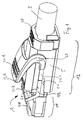
- FIG. 1 shown plug 1 is the plug, as shown in the EP 1 693 933 -
- the plug As shown in the EP 1 693 933 -
- EP 1 693 933 There, for example, based on the FIGS. 1 and 4 - is similar in type.
- Regarding the configuration of the plug its purpose and in particular its internal structure is expressly to this document EP 1 693 933 directed. A repetition of the description of parts and aspects of the connector described therein is omitted here.
- a strain relief for the cable 3 is formed by a clip-on bracket 18 which locks with the plug housing.
- other strain relief can be provided, for example.
- EP 1 693 933 described union nut In EP 1 693 933 described union nut.
- the housing 5 of the plug has a front, slimmer connector section 11 and a rear, cross-sectional larger second batch 12.
- FIG. 1 drawn embodiment of the inventive connector has an actuating element, which is in two parts here and a rocker arm 21 and a bracket 22 has.
- the bracket forms two as the motion transmission section acting spars 22.1 and the trip piece forming web 22.2, which extends outside the latch.
- the rocker arm 21 In the region of a pivot point 23, the rocker arm 21, not shown, on the inside (in corresponding openings of the housing inside) projecting pivot on.
- the actuating part which is formed by a top 21.1 of the rocker arm, the actuating element as a whole about the fulcrum (strictly speaking, it is about a rotation axis through the indicated pivot point and its opposite counterpart) pivots, whereby the web 22.2 the Pawl presses down and triggers.
- the provision in the drawn initial state is due to the spring force of the pawl 2.4.
- the rocker arm with molded pivot may, for example, be made of plastic, while the bracket 22 may be metallic.
- the actuator 31 relative to the housing 5 is not pivotable, but translationally displaceable in the axial direction.
- the actuator 31 is here in one piece. It has as the actuator according to FIG. 1 one on the pawl side and partially laterally extending actuating part with ribs 31.1, on both sides each laterally extending bars 31.2 and guided over the pawl web 31.3. By moving the actuating element along the arrow 32, the pawl 2.4 is pressed down and actuated.
- the housing may also have (not shown here) formations such as guide slots for the guidance of the actuating element and / or for forming end stops.
Landscapes
- Physics & Mathematics (AREA)
- General Physics & Mathematics (AREA)
- Optics & Photonics (AREA)
- Details Of Connecting Devices For Male And Female Coupling (AREA)
Applications Claiming Priority (1)
| Application Number | Priority Date | Filing Date | Title |
|---|---|---|---|
| CH18182007 | 2007-11-26 |
Publications (1)
| Publication Number | Publication Date |
|---|---|
| EP2063497A1 true EP2063497A1 (fr) | 2009-05-27 |
Family
ID=39247716
Family Applications (1)
| Application Number | Title | Priority Date | Filing Date |
|---|---|---|---|
| EP08405283A Withdrawn EP2063497A1 (fr) | 2007-11-26 | 2008-11-19 | Connecteur à fiches |
Country Status (1)
| Country | Link |
|---|---|
| EP (1) | EP2063497A1 (fr) |
Cited By (15)
| Publication number | Priority date | Publication date | Assignee | Title |
|---|---|---|---|---|
| WO2009135787A1 (fr) * | 2008-05-07 | 2009-11-12 | Huber+Suhner Ag | Connecteur enfichable à fonction de déverrouillage |
| EP2796908A1 (fr) * | 2013-04-24 | 2014-10-29 | Euromicron Werkzeuge GmbH | Connecteur à fibres optique ayant un emballage haute densité |
| DE202016103178U1 (de) | 2016-06-16 | 2016-07-07 | Reichle & De-Massari Ag | Steckverbinder |
| US9448370B2 (en) | 2012-02-20 | 2016-09-20 | Commscope Technologies Llc | Connector and connector assembly |
| US9684130B2 (en) | 2011-05-04 | 2017-06-20 | The Siemon Company | Fiber optic connector with polarity change |
| US9761998B2 (en) | 2011-02-08 | 2017-09-12 | Commscope Technologies Llc | Release tab for an electrical connector and electrical connector comprising said release tab |
| US9825403B2 (en) | 2011-02-08 | 2017-11-21 | Commscope Technologies Llc | RJ type connector including a disengagement feature acting on the latch of the connector |
| CN107394481A (zh) * | 2016-05-10 | 2017-11-24 | 利萨·德雷克塞迈尔有限责任公司 | 插接连接器壳体和插接连接器 |
| US10067301B2 (en) | 2014-01-13 | 2018-09-04 | Commscope Connectivity Uk Limited | Fiber optic connector |
| WO2019011068A1 (fr) * | 2017-07-10 | 2019-01-17 | 清远市亿源通光电科技有限公司 | Connecteur de fibre optique |
| WO2019080497A1 (fr) * | 2017-10-26 | 2019-05-02 | 清远市亿源通光电科技有限公司 | Connecteur de fibre optique |
| CN111355081A (zh) * | 2020-03-25 | 2020-06-30 | 上海航天科工电器研究院有限公司 | 一种连接器的线缆夹持机构 |
| US11215767B2 (en) | 2017-06-07 | 2022-01-04 | Commscope Technologies Llc | Fiber optic adapter and cassette |
| US11327240B2 (en) | 2017-09-15 | 2022-05-10 | Commscope Technologies Llc | Fiber optic connector with boot-integrated release and related assemblies |
| USRE49942E1 (en) * | 2011-10-05 | 2024-04-23 | Senko Advanced Components, Inc. | Latching connector with remote release |
Citations (9)
| Publication number | Priority date | Publication date | Assignee | Title |
|---|---|---|---|---|
| EP0899827A2 (fr) * | 1997-09-03 | 1999-03-03 | Lucent Technologies Inc. | Structure d'assemblage avec faible bruit diaphonique pour connecteur de communication |
| US6364685B1 (en) * | 2000-11-03 | 2002-04-02 | Randy Marshall Manning | Connector with articulated latch |
| US20050054230A1 (en) * | 2003-09-10 | 2005-03-10 | Kui-Hsien Huang | Structure of a communication internet connector |
| WO2005041363A1 (fr) * | 2003-10-10 | 2005-05-06 | Fci | Connecteur de cable a verrouillage ameliore |
| DE102004038123A1 (de) | 2004-08-05 | 2006-02-23 | Tyco Electronics Amp Gmbh | Elektrischer Stecker und elektrische Steckeraufnahme |
| CH695523A5 (de) | 2001-03-21 | 2006-06-15 | Reichle & De Massari Fa | Schutzvorrichtung für eine Steckverbindung. |
| EP1693933A1 (fr) | 2005-02-17 | 2006-08-23 | Reichle & De-Massari AG | Connecteur pour la transmission de données par des fils électriques |
| US7101212B1 (en) | 2005-03-07 | 2006-09-05 | Kevin Larkin | Snagless plug and boot connection |
| WO2007044310A1 (fr) | 2005-10-05 | 2007-04-19 | Tyco Electronics Corporation | Fiche modulaire dotee d’un element de verrouillage coulissant |
-
2008
- 2008-11-19 EP EP08405283A patent/EP2063497A1/fr not_active Withdrawn
Patent Citations (10)
| Publication number | Priority date | Publication date | Assignee | Title |
|---|---|---|---|---|
| EP0899827A2 (fr) * | 1997-09-03 | 1999-03-03 | Lucent Technologies Inc. | Structure d'assemblage avec faible bruit diaphonique pour connecteur de communication |
| US6364685B1 (en) * | 2000-11-03 | 2002-04-02 | Randy Marshall Manning | Connector with articulated latch |
| CH695523A5 (de) | 2001-03-21 | 2006-06-15 | Reichle & De Massari Fa | Schutzvorrichtung für eine Steckverbindung. |
| US20050054230A1 (en) * | 2003-09-10 | 2005-03-10 | Kui-Hsien Huang | Structure of a communication internet connector |
| US6866532B1 (en) | 2003-09-10 | 2005-03-15 | Kui-Hsien Huang | Structure of a communication internet connector |
| WO2005041363A1 (fr) * | 2003-10-10 | 2005-05-06 | Fci | Connecteur de cable a verrouillage ameliore |
| DE102004038123A1 (de) | 2004-08-05 | 2006-02-23 | Tyco Electronics Amp Gmbh | Elektrischer Stecker und elektrische Steckeraufnahme |
| EP1693933A1 (fr) | 2005-02-17 | 2006-08-23 | Reichle & De-Massari AG | Connecteur pour la transmission de données par des fils électriques |
| US7101212B1 (en) | 2005-03-07 | 2006-09-05 | Kevin Larkin | Snagless plug and boot connection |
| WO2007044310A1 (fr) | 2005-10-05 | 2007-04-19 | Tyco Electronics Corporation | Fiche modulaire dotee d’un element de verrouillage coulissant |
Cited By (28)
| Publication number | Priority date | Publication date | Assignee | Title |
|---|---|---|---|---|
| WO2009135787A1 (fr) * | 2008-05-07 | 2009-11-12 | Huber+Suhner Ag | Connecteur enfichable à fonction de déverrouillage |
| US8221007B2 (en) | 2008-05-07 | 2012-07-17 | Huber+Suhner Ag | Plug connector having unlocking mechanism |
| US11322889B2 (en) | 2011-02-08 | 2022-05-03 | Commscope Technologies Llc | RJ type connector including a disengagement feature acting on the latch of the connector |
| US9991635B2 (en) | 2011-02-08 | 2018-06-05 | Commscope Technologies Llc | Release tab for an electrical connector and electrical connector comprising said release tab |
| US9761998B2 (en) | 2011-02-08 | 2017-09-12 | Commscope Technologies Llc | Release tab for an electrical connector and electrical connector comprising said release tab |
| US9825403B2 (en) | 2011-02-08 | 2017-11-21 | Commscope Technologies Llc | RJ type connector including a disengagement feature acting on the latch of the connector |
| US11742617B2 (en) | 2011-02-08 | 2023-08-29 | Commscope Technologies Llc | RJ type connector including a disengagement feature acting on the latch of the connector |
| US10228516B2 (en) | 2011-05-04 | 2019-03-12 | The Siemon Company | Fiber optic connector with polarity change |
| US9684130B2 (en) | 2011-05-04 | 2017-06-20 | The Siemon Company | Fiber optic connector with polarity change |
| USRE49942E1 (en) * | 2011-10-05 | 2024-04-23 | Senko Advanced Components, Inc. | Latching connector with remote release |
| US9448370B2 (en) | 2012-02-20 | 2016-09-20 | Commscope Technologies Llc | Connector and connector assembly |
| WO2014173993A1 (fr) * | 2013-04-24 | 2014-10-30 | Euromicron Werkzeuge Gmbh | Élément de connexion optique enfichable pouvant être conditionné de manière compacte |
| EP2796908A1 (fr) * | 2013-04-24 | 2014-10-29 | Euromicron Werkzeuge GmbH | Connecteur à fibres optique ayant un emballage haute densité |
| US10067301B2 (en) | 2014-01-13 | 2018-09-04 | Commscope Connectivity Uk Limited | Fiber optic connector |
| US11604319B2 (en) | 2014-01-13 | 2023-03-14 | Commscope Connectivity Uk Limited | Fiber optic connector |
| US11079556B2 (en) | 2014-01-13 | 2021-08-03 | Commscope Connectivity Uk Limited | Fiber optic connector |
| US10545296B2 (en) | 2014-01-13 | 2020-01-28 | Commscope Connectivity Uk Limited | Fiber optic connector |
| CN107394481A (zh) * | 2016-05-10 | 2017-11-24 | 利萨·德雷克塞迈尔有限责任公司 | 插接连接器壳体和插接连接器 |
| EP3971624A1 (fr) | 2016-06-16 | 2022-03-23 | Reichle & De-Massari AG | Connecteur enfichable |
| DE202016103178U1 (de) | 2016-06-16 | 2016-07-07 | Reichle & De-Massari Ag | Steckverbinder |
| EP3258300A1 (fr) | 2016-06-16 | 2017-12-20 | Reichle & De-Massari AG | Connecteur enfichable |
| US11215767B2 (en) | 2017-06-07 | 2022-01-04 | Commscope Technologies Llc | Fiber optic adapter and cassette |
| US11650378B2 (en) | 2017-06-07 | 2023-05-16 | Commscope Technologies Llc | Fiber optic adapter and cassette |
| WO2019011068A1 (fr) * | 2017-07-10 | 2019-01-17 | 清远市亿源通光电科技有限公司 | Connecteur de fibre optique |
| US11327240B2 (en) | 2017-09-15 | 2022-05-10 | Commscope Technologies Llc | Fiber optic connector with boot-integrated release and related assemblies |
| US11592626B2 (en) | 2017-09-15 | 2023-02-28 | Commscope Technologies Llc | Fiber optic connector with boot-integrated release and related assemblies |
| WO2019080497A1 (fr) * | 2017-10-26 | 2019-05-02 | 清远市亿源通光电科技有限公司 | Connecteur de fibre optique |
| CN111355081A (zh) * | 2020-03-25 | 2020-06-30 | 上海航天科工电器研究院有限公司 | 一种连接器的线缆夹持机构 |
Similar Documents
| Publication | Publication Date | Title |
|---|---|---|
| EP2063497A1 (fr) | Connecteur à fiches | |
| DE69924430T2 (de) | Elektrischer Steckverbinder mit Verriegelungshebel | |
| DE60132090T2 (de) | Verbinder mit hebel | |
| DE69724011T2 (de) | Optischer steckverbinder | |
| DE102014114026B4 (de) | Leiteranschlussklemme und Verfahren zu deren Montage | |
| DE60016140T2 (de) | Verriegelungsmechanismus in Verbindern | |
| EP1207588B1 (fr) | Connecteur électrique pour cable plat ou circuit imprimé flexible | |
| EP1972037B1 (fr) | Douille enfichable électrique | |
| DE102009006441B4 (de) | Leichtkraftsteckverbinder | |
| DE102008035193A1 (de) | Kontrollierbare Steckverbindung und Verfahren zur Kontrolle des Steckzustandes einer Steckverbindung | |
| DE112018004678T5 (de) | Stecker | |
| DE69834360T2 (de) | Verbinder mit Schnellkupplungs- bzw. Entkupplungsmechanismus und Verfahren zum Entkopplen eines solchen Verbinders | |
| DE102012005043A1 (de) | Elektrische Wanddurchführung für Solaranlagen | |
| DE102018212911A1 (de) | Verbindungseinrichtung | |
| EP3553894B1 (fr) | Structure de connexion et connecteur | |
| DE19543009C2 (de) | Verriegelungsmechanismus für ein elektrisches Steckverbinderpaar | |
| DE60207643T2 (de) | Steckverbinder mit Hebeleinrichtung | |
| DE102016201535B4 (de) | Elektrischer Verbinder | |
| DE102017107943B3 (de) | Verriegelungsmechanismus zur lösbaren Verriegelung eines ersten Bauteils an einem zweiten Bauteil sowie damit gebildete Anordnung | |
| WO2007020020A1 (fr) | Connecteur electrique enfichable | |
| DE69920372T2 (de) | Ausfallsicherer optischer Verbinder | |
| DE60218944T2 (de) | Steckverbinder | |
| DE19808683C2 (de) | Leichtkraft-Steckverbindung | |
| DE19916500B4 (de) | Aufbau eines Hebels für eine Steckverbindung, bei der die Steckelemente durch den Hebel verbunden werden | |
| DE69834079T2 (de) | Selbstausrichtender elektrischer Steckerverbinder |
Legal Events
| Date | Code | Title | Description |
|---|---|---|---|
| PUAI | Public reference made under article 153(3) epc to a published international application that has entered the european phase |
Free format text: ORIGINAL CODE: 0009012 |
|
| AK | Designated contracting states |
Kind code of ref document: A1 Designated state(s): AT BE BG CH CY CZ DE DK EE ES FI FR GB GR HR HU IE IS IT LI LT LU LV MC MT NL NO PL PT RO SE SI SK TR |
|
| AX | Request for extension of the european patent |
Extension state: AL BA MK RS |
|
| AKX | Designation fees paid | ||
| REG | Reference to a national code |
Ref country code: DE Ref legal event code: 8566 |
|
| STAA | Information on the status of an ep patent application or granted ep patent |
Free format text: STATUS: THE APPLICATION IS DEEMED TO BE WITHDRAWN |
|
| 18D | Application deemed to be withdrawn |
Effective date: 20091128 |