EP2063497A1 - Connector - Google Patents
Connector Download PDFInfo
- Publication number
- EP2063497A1 EP2063497A1 EP08405283A EP08405283A EP2063497A1 EP 2063497 A1 EP2063497 A1 EP 2063497A1 EP 08405283 A EP08405283 A EP 08405283A EP 08405283 A EP08405283 A EP 08405283A EP 2063497 A1 EP2063497 A1 EP 2063497A1
- Authority
- EP
- European Patent Office
- Prior art keywords
- housing
- plug
- actuating element
- plug according
- latch
- Prior art date
- Legal status (The legal status is an assumption and is not a legal conclusion. Google has not performed a legal analysis and makes no representation as to the accuracy of the status listed.)
- Withdrawn
Links
Images

Classifications
-
- H—ELECTRICITY
- H01—ELECTRIC ELEMENTS
- H01R—ELECTRICALLY-CONDUCTIVE CONNECTIONS; STRUCTURAL ASSOCIATIONS OF A PLURALITY OF MUTUALLY-INSULATED ELECTRICAL CONNECTING ELEMENTS; COUPLING DEVICES; CURRENT COLLECTORS
- H01R13/00—Details of coupling devices of the kinds covered by groups H01R12/70 or H01R24/00 - H01R33/00
- H01R13/62—Means for facilitating engagement or disengagement of coupling parts or for holding them in engagement
- H01R13/629—Additional means for facilitating engagement or disengagement of coupling parts, e.g. aligning or guiding means, levers, gas pressure electrical locking indicators, manufacturing tolerances
- H01R13/633—Additional means for facilitating engagement or disengagement of coupling parts, e.g. aligning or guiding means, levers, gas pressure electrical locking indicators, manufacturing tolerances for disengagement only
- H01R13/6335—Additional means for facilitating engagement or disengagement of coupling parts, e.g. aligning or guiding means, levers, gas pressure electrical locking indicators, manufacturing tolerances for disengagement only comprising a handle
-
- G—PHYSICS
- G02—OPTICS
- G02B—OPTICAL ELEMENTS, SYSTEMS OR APPARATUS
- G02B6/00—Light guides; Structural details of arrangements comprising light guides and other optical elements, e.g. couplings
- G02B6/24—Coupling light guides
- G02B6/36—Mechanical coupling means
- G02B6/38—Mechanical coupling means having fibre to fibre mating means
- G02B6/3807—Dismountable connectors, i.e. comprising plugs
- G02B6/389—Dismountable connectors, i.e. comprising plugs characterised by the method of fastening connecting plugs and sockets, e.g. screw- or nut-lock, snap-in, bayonet type
- G02B6/3893—Push-pull type, e.g. snap-in, push-on
-
- H—ELECTRICITY
- H01—ELECTRIC ELEMENTS
- H01R—ELECTRICALLY-CONDUCTIVE CONNECTIONS; STRUCTURAL ASSOCIATIONS OF A PLURALITY OF MUTUALLY-INSULATED ELECTRICAL CONNECTING ELEMENTS; COUPLING DEVICES; CURRENT COLLECTORS
- H01R13/00—Details of coupling devices of the kinds covered by groups H01R12/70 or H01R24/00 - H01R33/00
- H01R13/58—Means for relieving strain on wire connection, e.g. cord grip, for avoiding loosening of connections between wires and terminals within a coupling device terminating a cable
- H01R13/5804—Means for relieving strain on wire connection, e.g. cord grip, for avoiding loosening of connections between wires and terminals within a coupling device terminating a cable comprising a separate cable clamping part
- H01R13/5812—Means for relieving strain on wire connection, e.g. cord grip, for avoiding loosening of connections between wires and terminals within a coupling device terminating a cable comprising a separate cable clamping part the cable clamping being achieved by mounting the separate part on the housing of the coupling device
-
- H—ELECTRICITY
- H01—ELECTRIC ELEMENTS
- H01R—ELECTRICALLY-CONDUCTIVE CONNECTIONS; STRUCTURAL ASSOCIATIONS OF A PLURALITY OF MUTUALLY-INSULATED ELECTRICAL CONNECTING ELEMENTS; COUPLING DEVICES; CURRENT COLLECTORS
- H01R24/00—Two-part coupling devices, or either of their cooperating parts, characterised by their overall structure
- H01R24/60—Contacts spaced along planar side wall transverse to longitudinal axis of engagement
- H01R24/62—Sliding engagements with one side only, e.g. modular jack coupling devices
- H01R24/64—Sliding engagements with one side only, e.g. modular jack coupling devices for high frequency, e.g. RJ 45
Definitions
- the present invention relates to a connector for data transmission and telecommunications, in particular electrical cables with a plurality of electrical conductors and / or optical cables with at least one light guide.
- connectors with a latching mechanism so that once plugged in does not come loose without the user's intention.
- Particularly well-known and popular are connectors in which the plug has a latch, through which the latching of the plug is effected with the socket; wherein the latching connection with a simple to betechnikstelligenden by hand operation of the latch is releasable.
- a worldwide popular connector of this type is, for example, the connector system type RJ45.
- top-mounted operating levers or the like may be hampered depending on the configuration for geometric reasons of elements such as protruding collar or other elements of the socket. Therefore were Plug of the type mentioned with widened backside portion not previously suitable for female connector assemblies with protruding elements.
- An example of a connector type with widened backside lot is the one in the font EP 1 693 933 described plug, an example of previously unsuitable sockets with collar collar is the Siemens Industrial Ethernet Scalance X-100 product line.
- the inventive plug with housing and latch is characterized essentially by an actuating element, which is provided on the housing and relative to this (or the part which carries the latch) is movable.
- the actuator extends at least partially along one of the top side (ie the latch side) different side, for example. Side along both sides.
- the actuating element can extend completely laterally and / or possibly on the opposite side of the latch side, in particular in the region of the transition between a plug section and a second (rear) section, and be free from parts arranged along the latch side.
- the actuating element allows the direct and / or possibly indirect transfer of a movement from the operating section to the release section.
- the actuating element acts in the manner of a rocker arm or a slider, wherein, as indicated, a force transmission takes place along the side other than the top side.
- the actuator or ajasübetragungspartie thereof may be arranged on the outside of the housing, which is a particularly easy to implement arrangement. Thesecuresübetragungspartie can be guided directly along the housing.
- the actuating element can also extend in regions under a housing surface-for example, in a space between an inner housing part and an outer housing part-along the housing. "Along a side different from the latch side (the first side)" is then also to be understood in relation to the plug axis and the information transmitting elements (i.e., electrical conductors / contacts or optical fibers).
- An actuating part of the actuating element can also be present in the construction according to the invention readily on the pawl side, which is even preferred. It is designed and designed to engage the user's finger or possibly a tool, and is accessible, even when the connector is plugged into the socket in tight spaces.
- the actuating element may have a rocker arm which is fastened or attachable to the housing, wherein a triggering part of the actuating element triggers the latching pawl upon actuation of the rocker arm.
- top refers to directions that are radial with respect to a connector axis.
- Top or “pawl side” generally refers to the lateral side of the plug housing on which the latch is present (although in applications and literature one often sees arrangements in which the latch is “down”).
- the opposite side of the jack side opposite side.
- Sideways refers to sidewalls and directions that are perpendicular to the latch side.
- front or “front” refers to the axial direction to the connector end (to the connector), “rear” is the opposite direction (toward the cable).
- the housing of the plug can be constructed in one piece or in several parts; it may consist of the at least one part forming the actual plug section or may additionally have an over-housing; In the present text, differences between different housing parts are not discussed.
- FIG. 1 shown plug 1 is the plug, as shown in the EP 1 693 933 -
- the plug As shown in the EP 1 693 933 -
- EP 1 693 933 There, for example, based on the FIGS. 1 and 4 - is similar in type.
- Regarding the configuration of the plug its purpose and in particular its internal structure is expressly to this document EP 1 693 933 directed. A repetition of the description of parts and aspects of the connector described therein is omitted here.
- a strain relief for the cable 3 is formed by a clip-on bracket 18 which locks with the plug housing.
- other strain relief can be provided, for example.
- EP 1 693 933 described union nut In EP 1 693 933 described union nut.
- the housing 5 of the plug has a front, slimmer connector section 11 and a rear, cross-sectional larger second batch 12.
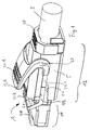
- FIG. 1 drawn embodiment of the inventive connector has an actuating element, which is in two parts here and a rocker arm 21 and a bracket 22 has.
- the bracket forms two as the motion transmission section acting spars 22.1 and the trip piece forming web 22.2, which extends outside the latch.
- the rocker arm 21 In the region of a pivot point 23, the rocker arm 21, not shown, on the inside (in corresponding openings of the housing inside) projecting pivot on.
- the actuating part which is formed by a top 21.1 of the rocker arm, the actuating element as a whole about the fulcrum (strictly speaking, it is about a rotation axis through the indicated pivot point and its opposite counterpart) pivots, whereby the web 22.2 the Pawl presses down and triggers.
- the provision in the drawn initial state is due to the spring force of the pawl 2.4.
- the rocker arm with molded pivot may, for example, be made of plastic, while the bracket 22 may be metallic.
- the actuator 31 relative to the housing 5 is not pivotable, but translationally displaceable in the axial direction.
- the actuator 31 is here in one piece. It has as the actuator according to FIG. 1 one on the pawl side and partially laterally extending actuating part with ribs 31.1, on both sides each laterally extending bars 31.2 and guided over the pawl web 31.3. By moving the actuating element along the arrow 32, the pawl 2.4 is pressed down and actuated.
- the housing may also have (not shown here) formations such as guide slots for the guidance of the actuating element and / or for forming end stops.
Landscapes
- Physics & Mathematics (AREA)
- General Physics & Mathematics (AREA)
- Optics & Photonics (AREA)
- Details Of Connecting Devices For Male And Female Coupling (AREA)
Abstract
Description
Die vorliegende Erfindung betrifft einen Steckverbinder für die Datenübertragung und Telekommunikation, insbesondere elektrische Kabel mit einer Mehrzahl von elektrischen Leitern und/oder optische Kabel mit mindestens einem Lichtleiter.The present invention relates to a connector for data transmission and telecommunications, in particular electrical cables with a plurality of electrical conductors and / or optical cables with at least one light guide.
Die zunehmende Digitalisierung in allen Bereichen des täglichen Lebens führt dazu, dass Datenübertragungsleitungen und mit ihnen auch entsprechende Steckverbindungen von ständig zunehmender Bedeutung sind und zwar sowohl im Telekommunikations- und Bürobereich als auch in anderen Bereichen, namentlich dem Industrie-, der Gebäudeautomatisierungs- und der Audiobereich. Dabei wachsen mit den Anforderungen an die Datenleitungen auch die Anforderungen an die Steckverbindungen. Insbesondere müssen die Steckverbindungsteile - Stecker und Steckerbuchsen - auf immer kleinerem Raum immer mehr Funktionen wahrnehmen.The increasing digitization in all areas of daily life means that data transmission lines and, with them, corresponding connections, are becoming increasingly important, in the telecommunications and office sectors as well as in other areas, namely the industrial, building automation and audio sectors , At the same time, the requirements placed on the connectors grow with the demands on the data cables. In particular, the connector parts - plugs and sockets - have to perform more and more functions in ever smaller space.
Es ist üblich, Steckverbindungen mit einem Verrastmechanismus zu versehen, so dass ein einmal eingesteckter Stecker sich nicht ohne Absicht eines Benutzers löst. Besonders bekannt und populär sind Steckverbindungen, bei denen der Stecker eine Rastklinke aufweist, durch die die Verrastung des Steckers mit der Steckerbuchse bewirkt wird; wobei die Rastverbindung mit einer einfach von Hand zu bewerkstelligenden Betätigung der Rastklinke lösbar ist. Ein weltweit verbreitete Steckverbindung dieser Art ist bspw. das Steckverbindungssystem vom Typ RJ45.It is common to provide connectors with a latching mechanism so that once plugged in does not come loose without the user's intention. Particularly well-known and popular are connectors in which the plug has a latch, through which the latching of the plug is effected with the socket; wherein the latching connection with a simple to bewerkstelligenden by hand operation of the latch is releasable. A worldwide popular connector of this type is, for example, the connector system type RJ45.
Insbesondere in Anordnungen, in denen viele Steckplätze nebeneinander vorhanden sind oder in denen sich vor der jeweiligen Steckerbuchse Bauteile befinden - bspw. aussen vorstehende Kragen zur mechanischen Stabilisierung der Stecker - kann es manchmal mühsam oder fast unmöglich sein, die Rastklinke von Hand zu bedienen, da ihre Zugänglichkeit eingeschränkt ist. Zur Lösung dieses Problems wurden schon verschiedentlich Mechanismen vorgeschlagen. Diese sehen vor, dass entweder die Rastklinke durch ein separates, von der Steckerbuchse entferntes Betätigungsmittel betätigt werden kann, oder die das Verlängern der Rastklinke "nach hinten", in einen von der Steckerbuchse entfernteren Bereich vorsehen. Als Beispiele seien die Schriften
Allen diesen Beispielen ist gemein, dass sie einen Betätigungsmechanismus mit Elementen vorsehen, die entweder auf der Klinkenseite (mit 'Klinkenseite' oder 'Oberseite' ist diejenige Steckerseite gemeint, an der auch die Klinke vorhanden ist) oder mindestens teilweise im Innern des Gehäuses angeordnet sind. Das ist in vielen Situationen eine befriedigende Lösung. Es gibt aber vermehrt Stecker, die eine in die entsprechende Steckerbuchse passende, vorderseitige Steckerpartie und daran anschliessend eine im Querschnitt grössere, hinterseitige Partie aufweisen. Diese hinterseitige Partie kann datenleitungstypische Bauteile fassen, bspw. Beschaltungsmittel für elektrische Datenleitungen, oder Führungsmittel etc. für optische Datenleiter. Es kommt oft vor, dass aus Platzgründen im Innern des Gehäuses kein Betätigungmechanismus Platz hat. Die Bewegungsfreiheit von oberseitig angebrachten Betätigungshebeln oder dergleichen kann je nach Konfiguration aus geometrischen Gründen von Elementen wie bspw. vorstehenden Kragen oder anderen Elementen der Steckerbuchse behindert sein. Daher waren Stecker des genannten Typs mit verbreiterter hinterseitiger Partie bisher nicht für Steckerbuchsenanordnungen mit vorstehenden Elementen geeignet.All these examples have in common that they provide an actuating mechanism with elements that either on the latch side (with 'jack side' or 'top' is that plug side on which the pawl is present) or at least partially disposed in the interior of the housing , This is a satisfactory solution in many situations. But there are more plugs, which have a matching plug socket in the front side plug part and then a cross-sectionally larger, rear side game. This rear-side part can hold data-line-typical components, for example, wiring means for electrical data lines, or guide means, etc., for optical data conductors. It often happens that space reasons in the interior of the housing has no operating mechanism space. The freedom of movement of top-mounted operating levers or the like may be hampered depending on the configuration for geometric reasons of elements such as protruding collar or other elements of the socket. Therefore were Plug of the type mentioned with widened backside portion not previously suitable for female connector assemblies with protruding elements.
Ein Beispiel für einen Steckertyp mit verbreiterter hinterseitiger Partie ist der in der Schrift
Es ist folglich Aufgabe der Erfindung, einen Stecker mit Klinke zur Verfügung zu stellen, welcher die Betätigung der Klinke in Steckerbuchsenanordnungen ermöglicht, in denen das bisher nicht möglich war.It is therefore an object of the invention to provide a plug with jack, which allows the operation of the jack in female connector arrangements in which this was not previously possible.
Diese Aufgabe wird gelöst durch einen Stecker wie er in den Patentansprüchen definiert ist.This object is achieved by a connector as defined in the claims.
Der erfindungsgemässe Stecker mit Gehäuse und Rastklinke zeichnet sich im Wesentlichen durch ein Betätigungselement aus, welches am Gehäuse vorhanden und relativ zu diesem (bzw. dem Teil, der die Rastklinke trägt) bewegbar ist. Das Betätigungselement verläuft mindestens bereichsweise entlang einer von der Oberseite (d.h. der Klinkenseite) verschiedenen Seite, bspw. seitlich entlang beiden Seiten. Mit anderen Worten kann das Betätigungselement insbesondere im Bereich des Übergangs zwischen einer Steckerpartie und einer querschnittsgrösseren zweiten (hinterseitigen) Partie vollständig seitlich und/oder eventuell auf der Gegenseite der Klinkenseite verlaufen und frei von entlang der Klinkenseite angeordneten Teilen sein. Das Betätigungselement erlaubt die unmittelbare und/oder ggf. mittelbare Übertragung einer Bewegung von der Betätigungspartie auf die Auslösepartie. Es ist im Allgemeinen formsteif und/oder frei von bei der Auslösebewegung gegeneinander bewegbaren Teilen und/oder eventuell einstückig. Beispielsweise wirkt das Betätigungselement in der Art eines Kipphebels oder eines Schiebers, wobei wie angedeutet eine Kraftübertragung entlang der von der Oberseite verschiedenen Seite stattfindet.The inventive plug with housing and latch is characterized essentially by an actuating element, which is provided on the housing and relative to this (or the part which carries the latch) is movable. The actuator extends at least partially along one of the top side (ie the latch side) different side, for example. Side along both sides. In other words, the actuating element can extend completely laterally and / or possibly on the opposite side of the latch side, in particular in the region of the transition between a plug section and a second (rear) section, and be free from parts arranged along the latch side. The actuating element allows the direct and / or possibly indirect transfer of a movement from the operating section to the release section. It is generally dimensionally stable and / or free from each other in the tripping movement movable parts and / or possibly in one piece. For example, the actuating element acts in the manner of a rocker arm or a slider, wherein, as indicated, a force transmission takes place along the side other than the top side.
Zum Beispiel kann das Betätigungselement bzw. eine Bewegungsübetragungspartie davon aussenseitig am Gehäuse angeordnet sein, was eine besonders einfach zu realisierende Anordnung darstellt. Die Bewegungsübetragungspartie kann dabei unmittelbar dem Gehäuse entlang geführt sein. Alternativ dazu kann das Betätigungselement auch bereichsweise unter einer Gehäuseoberfläche - bspw. in einem Zwischenraum zwischen einem inneren Gehäuseteil und einem Übergehäuseteil - entlang dem Gehäuse verlaufen. "Entlang einer von der Klinkenseite (der ersten Seite) verschiedenen Seite" ist dann auch im Bezug auf die Steckerachse und die informationsübertragenden Elemente (d.h. elektrische Leiter/Kontakte bzw. Lichtleiter) zu verstehen.For example, the actuator or a Bewegungsübetragungspartie thereof may be arranged on the outside of the housing, which is a particularly easy to implement arrangement. The Bewegungsübetragungspartie can be guided directly along the housing. Alternatively, the actuating element can also extend in regions under a housing surface-for example, in a space between an inner housing part and an outer housing part-along the housing. "Along a side different from the latch side (the first side)" is then also to be understood in relation to the plug axis and the information transmitting elements (i.e., electrical conductors / contacts or optical fibers).
Durch diese an sich einfache Massnahme wird die eingangs gestellte Aufgabe gelöst. Eine Bewegung eines entlang der Oberseite angeordneten Betätigungselements würde nämlich - damit die Klinke betätigt werden kann - aus geometrischen Gründen immer Bewegungsspielraum und damit (nicht vorhandenen) Platz um das Gehäuse herum benötigen, und zwar insbesondere auch im Bereich des Übergangs zwischen einer Steckerpartie und einer querschnittsgrösseren zweiten (hinterseitigen) Partie.By this simple measure, the initially stated object is achieved. A movement of an actuating element arranged along the upper side would namely - so that the pawl can be actuated - geometric reasons always room for movement and thus (non-existent) space around the housing around, in particular in the region of the transition between a plug portion and a Querschnittsschnittsgrösseren second (back) game.
Bei einer seitlichen Führung des Betätigungselements ist das nicht der Fall. Vielmehr kann die Bewegung des Betätigungselements vollständig entlang der Seitenwand des Gehäuses erfolgen, ohne Bewegungskomponenten senkrecht zur GehäuseSeitenwand. Bei einer eventuellen unterseitigen (auf der Gegenseite zur Klinkenseite) Führung des Betätigungselements kann eine Bewegungsübertragungspartie des Betätigungselements in der Art eines Bandes flexibel biegbar ausgeformt sein, da es nur Zugkräfte übertragen muss (die Klinke muss "nach unten" gezogen werden). Dadurch kann das Betätigungselement ebenfalls entlang der Gegenwand geführt werden. In beiden Fällen beschränkt sich der laterale Platzbedarf auf die laterale Ausdehnung des Betätigungselementes. Es ist also mindestens im Bereich des genannten Übergangs kein zusätzlicher Bewegungsspielraum erforderlich.In a lateral guidance of the actuating element that is not the case. Rather, the movement of the actuating element can take place completely along the side wall of the housing, without movement components perpendicular to the housing side wall. In case of an underside (on the opposite side to the Pawl side) guide the actuator, a Bewegungsübertragungspartie of the actuator in the manner of a band be flexibly flexible formed, since it only has to transmit tensile forces (the pawl must be "pulled down"). As a result, the actuating element can also be guided along the opposite wall. In both cases, the lateral space requirement is limited to the lateral extent of the actuating element. Thus, at least in the area of said transition, no additional room for maneuver is required.
Eine Betätigungspartie des Betätigungselementes kann auch bei der erfindungsgemässen Konstruktion ohne Weiteres auf der Klinkenseite vorhanden sein, was sogar bevorzugt ist. Sie ist dafür vorgesehen und ausgebildet, dass der Finger oder eventuell ein Werkzeug des Benutzers daran angreift, und sie ist entsprechend zugänglich, auch wenn der Stecker bei engen Platzverhältnissen in die Buchse eingesteckt ist.An actuating part of the actuating element can also be present in the construction according to the invention readily on the pawl side, which is even preferred. It is designed and designed to engage the user's finger or possibly a tool, and is accessible, even when the connector is plugged into the socket in tight spaces.
Beispielsweise kann das Betätigungselement einen Kipphebel aufweisen, der am Gehäuse befestigt oder befestigbar ist, wobei eine Auslösepartie des Betätigungselement bei Betätigung des Kipphebels die Rastklinke auslöst.For example, the actuating element may have a rocker arm which is fastened or attachable to the housing, wherein a triggering part of the actuating element triggers the latching pawl upon actuation of the rocker arm.
Die in diesem Text verwendeten, die Orientierung betreffenden Bezeichnungen wie "Oberseite", "Vorderseite" etc. werden nur zur besseren Verständlichkeit verwendet und sind keinesfalls so zu verstehen, dass sie Anwendungen des Steckers auf bestimmte Orientierungen beschränken. "lateral" bezieht sich auf Richtungen, die betreffend einer Steckerachse radial sind. "Oberseite" oder "Klinkenseite" bezeichnet generell die laterale Seite des Steckergehäuses, an der die Klinke vorhanden ist (auch wenn man in Anwendungen und Literatur oft Anordnugen sieht, bei denen die Klinke "unten" ist). Die Gegenseite die der Klinkenseite gegenüberliegende Seite. "Seitlich" bezieht sich auf Seitenwände und Richtungen, die senkrecht zur Klinkenseite sind. Mit "vorne" oder "Vorderseite" ist die axiale Richtung zum steckerseitigen Ende (zur Steckerbuchse) hin bezeichnet, "hinten" ist die entgegengesetzte Richtung (zum Kabel hin).The terms used in this text, such as "top,""front," etc., are used for convenience only and are not to be construed as limiting applications of the plug to particular orientations. "lateral" refers to directions that are radial with respect to a connector axis. "Top" or "pawl side" generally refers to the lateral side of the plug housing on which the latch is present (although in applications and literature one often sees arrangements in which the latch is "down"). The opposite side of the jack side opposite side. "Sideways" refers to sidewalls and directions that are perpendicular to the latch side. The term "front" or "front" refers to the axial direction to the connector end (to the connector), "rear" is the opposite direction (toward the cable).
Das Gehäuse des Steckers kann einstückig oder mehrteilig aufgebaut sein, es kann aus dem mindestens einen die eigentliche Steckerpartie bildenden Teil bestehen oder zusätzlich noch ein Übergehäuse aufweisen; im vorliegenden Text wird nicht auf Unterschiede zwischen verschiedenen Gehäuseteilen eingegangen.The housing of the plug can be constructed in one piece or in several parts; it may consist of the at least one part forming the actual plug section or may additionally have an over-housing; In the present text, differences between different housing parts are not discussed.
Nachfolgend werden Ausführungsbeispiele des erfindungsgemässen Steckers anhand von Figuren beschrieben. Es zeigen:
-
Figur 1 eine Ansicht einer ersten Ausführungsform erfindungsgemässen Steckers; und -
Figur 2 eine Seitenansicht einer weiteren Ausführungsform erfindungsgemässen Steckers.
-
FIG. 1 a view of a first embodiment of the invention plug; and -
FIG. 2 a side view of another embodiment of the invention connector.
Der in
Im Unterschied zum in
Gut sichtbar in der
Die in
Auf der Oberseite (Klinkenseite) sind noch Rippen eingezeichnet, die die Betätigung erleichtern.On the top (pawl side) ribs are still drawn, which facilitate the operation.
Der Kipphebel mit angeformtem Drehzapfen kann bspw. aus Kunststoff gefertigt sein, während der Bügel 22 metallisch sein kann.The rocker arm with molded pivot may, for example, be made of plastic, while the
Am Gehäuse sind noch Anschlagkanten 5.1 vorhanden, die die Schwenkbewegung des Betätigungselements in beide Richtungen begrenzen.On the housing stop edges are still present 5.1, which limit the pivoting movement of the actuating element in both directions.
In der Variante gemäss
Das Gehäuse kann noch (hier nicht dargestellte) Ausformungen wie beispielsweise Führungsschlitze für die Führung des Betätigungselements und/oder zum Bilden von Endanschlägen aufweisen.The housing may also have (not shown here) formations such as guide slots for the guidance of the actuating element and / or for forming end stops.
Es sind viele weitere Varianten denkbar, unter anderem sowohl für schwenkbare als auch für translatorisch verschiebbare Betätigungselemente, die die erfindungsgemässe Betätigung einer Steckerklinke ermöglichen:
- eine Feder (bspw. Blattfeder), die die rückstellende Kraft der Klinke unterstützt; in der Ausführungsform gemäss
Fig. 1 könnte die Feder unterhalb der Betätigungspartie 21.1 liegen; - vom Gezeigten abweichende Materialwahl, bspw. ein einstückiges, metallisches oder aus Kunststoff bestehendes Betätigungselement, ein mindestens bereichsweise mit Kunststoff beschichtetes metallisches Betätigungselement etc.
- Aussenseitig am Gehäuse angeformte Vorsprünge zur Führung und/oder Bildung von Endanschlägen, die bspw. zapfenartig ausgebildet sein können, ggf. auch anstelle der Drehzapfen.
- a spring (eg leaf spring) which assists the restoring force of the pawl; in the embodiment according to
Fig. 1 could be the spring below the operating section 21.1; - from the shown different material choice, for example, a one-piece, metallic or plastic existing actuator, at least partially coated with plastic metallic actuator etc.
- On the outside of the housing molded projections for guiding and / or formation of end stops, which may be formed, for example, pin-like, possibly also instead of the pivot.
Für schwenkbare Betätigungselemente:
- In Umkehrung des Obigen, Vorsehen von Führungszapfen des Gehäuses, die in entsprechende Führungslöcher des Betätigungselements eingreifen und so den Drehpunkt für die Schwenkbewegung bilden
- Inversion of the above, provision of guide pins of the housing which engage in corresponding guide holes of the actuating element and thus form the pivot point for the pivoting movement
Für translatorisch verschiebbare Betätigungselemente:
- Das Betätigungselement kann auch an einem äusseren Gehäuseteil angeformt sein, so dass in der Art einer Push-Pull-Verbindung das Gehäuseteil als Ganzes verschiebbar ist und zum Entriegeln zurückgezogen werden muss.
- The actuating element may also be integrally formed on an outer housing part, so that in the manner of a push-pull connection, the housing part as a whole is displaceable and must be withdrawn for unlocking.
Und als grundlegend andere Variante:
- Vorsehen des Betätigungselements als mindestens ein unterseitig durch Führungsmittel geführtes, flexibles Band mit Lasche oder dergleichen zum Halten der Klinke und mit einem hinterseitigen Betätigungsknopf, der für die Betätigung entgegen der Federkraft der Klinke nach hinten zu ziehen ist.
- Provision of the actuating element as at least one guided on the underside by a guide means, flexible tape with tab or the like Holding the pawl and with a rear-side operating knob, which is to pull back against the spring force of the pawl for the actuation.
Viele weitere Varianten sind denkbar.Many other variants are conceivable.
Claims (10)
Applications Claiming Priority (1)
| Application Number | Priority Date | Filing Date | Title |
|---|---|---|---|
| CH18182007 | 2007-11-26 |
Publications (1)
| Publication Number | Publication Date |
|---|---|
| EP2063497A1 true EP2063497A1 (en) | 2009-05-27 |
Family
ID=39247716
Family Applications (1)
| Application Number | Title | Priority Date | Filing Date |
|---|---|---|---|
| EP08405283A Withdrawn EP2063497A1 (en) | 2007-11-26 | 2008-11-19 | Connector |
Country Status (1)
| Country | Link |
|---|---|
| EP (1) | EP2063497A1 (en) |
Cited By (15)
| Publication number | Priority date | Publication date | Assignee | Title |
|---|---|---|---|---|
| WO2009135787A1 (en) * | 2008-05-07 | 2009-11-12 | Huber+Suhner Ag | Plug connector having unlocking mechanism |
| EP2796908A1 (en) * | 2013-04-24 | 2014-10-29 | Euromicron Werkzeuge GmbH | Optical plug-in connection with high density packaging |
| DE202016103178U1 (en) | 2016-06-16 | 2016-07-07 | Reichle & De-Massari Ag | Connectors |
| US9448370B2 (en) | 2012-02-20 | 2016-09-20 | Commscope Technologies Llc | Connector and connector assembly |
| US9684130B2 (en) | 2011-05-04 | 2017-06-20 | The Siemon Company | Fiber optic connector with polarity change |
| US9761998B2 (en) | 2011-02-08 | 2017-09-12 | Commscope Technologies Llc | Release tab for an electrical connector and electrical connector comprising said release tab |
| US9825403B2 (en) | 2011-02-08 | 2017-11-21 | Commscope Technologies Llc | RJ type connector including a disengagement feature acting on the latch of the connector |
| CN107394481A (en) * | 2016-05-10 | 2017-11-24 | 利萨·德雷克塞迈尔有限责任公司 | Connectors housing and connectors |
| US10067301B2 (en) | 2014-01-13 | 2018-09-04 | Commscope Connectivity Uk Limited | Fiber optic connector |
| WO2019011068A1 (en) * | 2017-07-10 | 2019-01-17 | 清远市亿源通光电科技有限公司 | Optical fiber connector |
| WO2019080497A1 (en) * | 2017-10-26 | 2019-05-02 | 清远市亿源通光电科技有限公司 | Optical fiber connector |
| CN111355081A (en) * | 2020-03-25 | 2020-06-30 | 上海航天科工电器研究院有限公司 | Cable clamping mechanism of connector |
| US11215767B2 (en) | 2017-06-07 | 2022-01-04 | Commscope Technologies Llc | Fiber optic adapter and cassette |
| US11327240B2 (en) | 2017-09-15 | 2022-05-10 | Commscope Technologies Llc | Fiber optic connector with boot-integrated release and related assemblies |
| USRE49942E1 (en) * | 2011-10-05 | 2024-04-23 | Senko Advanced Components, Inc. | Latching connector with remote release |
Citations (9)
| Publication number | Priority date | Publication date | Assignee | Title |
|---|---|---|---|---|
| EP0899827A2 (en) * | 1997-09-03 | 1999-03-03 | Lucent Technologies Inc. | Low crosstalk assembly structure for use in a communication plug |
| US6364685B1 (en) * | 2000-11-03 | 2002-04-02 | Randy Marshall Manning | Connector with articulated latch |
| US20050054230A1 (en) * | 2003-09-10 | 2005-03-10 | Kui-Hsien Huang | Structure of a communication internet connector |
| WO2005041363A1 (en) * | 2003-10-10 | 2005-05-06 | Fci | Cable connector with improved latching |
| DE102004038123A1 (en) | 2004-08-05 | 2006-02-23 | Tyco Electronics Amp Gmbh | Electrical plug and electrical plug receptacle |
| CH695523A5 (en) | 2001-03-21 | 2006-06-15 | Reichle & De Massari Fa | Protector for plug connector, comprises seal which covers gap formed between guide member and plug housing |
| EP1693933A1 (en) | 2005-02-17 | 2006-08-23 | Reichle & De-Massari AG | Connector for data transmission via electrical wires |
| US7101212B1 (en) | 2005-03-07 | 2006-09-05 | Kevin Larkin | Snagless plug and boot connection |
| WO2007044310A1 (en) | 2005-10-05 | 2007-04-19 | Tyco Electronics Corporation | Modular plug with slider latch |
-
2008
- 2008-11-19 EP EP08405283A patent/EP2063497A1/en not_active Withdrawn
Patent Citations (10)
| Publication number | Priority date | Publication date | Assignee | Title |
|---|---|---|---|---|
| EP0899827A2 (en) * | 1997-09-03 | 1999-03-03 | Lucent Technologies Inc. | Low crosstalk assembly structure for use in a communication plug |
| US6364685B1 (en) * | 2000-11-03 | 2002-04-02 | Randy Marshall Manning | Connector with articulated latch |
| CH695523A5 (en) | 2001-03-21 | 2006-06-15 | Reichle & De Massari Fa | Protector for plug connector, comprises seal which covers gap formed between guide member and plug housing |
| US20050054230A1 (en) * | 2003-09-10 | 2005-03-10 | Kui-Hsien Huang | Structure of a communication internet connector |
| US6866532B1 (en) | 2003-09-10 | 2005-03-15 | Kui-Hsien Huang | Structure of a communication internet connector |
| WO2005041363A1 (en) * | 2003-10-10 | 2005-05-06 | Fci | Cable connector with improved latching |
| DE102004038123A1 (en) | 2004-08-05 | 2006-02-23 | Tyco Electronics Amp Gmbh | Electrical plug and electrical plug receptacle |
| EP1693933A1 (en) | 2005-02-17 | 2006-08-23 | Reichle & De-Massari AG | Connector for data transmission via electrical wires |
| US7101212B1 (en) | 2005-03-07 | 2006-09-05 | Kevin Larkin | Snagless plug and boot connection |
| WO2007044310A1 (en) | 2005-10-05 | 2007-04-19 | Tyco Electronics Corporation | Modular plug with slider latch |
Cited By (29)
| Publication number | Priority date | Publication date | Assignee | Title |
|---|---|---|---|---|
| WO2009135787A1 (en) * | 2008-05-07 | 2009-11-12 | Huber+Suhner Ag | Plug connector having unlocking mechanism |
| US8221007B2 (en) | 2008-05-07 | 2012-07-17 | Huber+Suhner Ag | Plug connector having unlocking mechanism |
| US11322889B2 (en) | 2011-02-08 | 2022-05-03 | Commscope Technologies Llc | RJ type connector including a disengagement feature acting on the latch of the connector |
| US12088044B2 (en) | 2011-02-08 | 2024-09-10 | Commscope Technologies Llc | Connector including a disengagement feature |
| US9761998B2 (en) | 2011-02-08 | 2017-09-12 | Commscope Technologies Llc | Release tab for an electrical connector and electrical connector comprising said release tab |
| US9825403B2 (en) | 2011-02-08 | 2017-11-21 | Commscope Technologies Llc | RJ type connector including a disengagement feature acting on the latch of the connector |
| US11742617B2 (en) | 2011-02-08 | 2023-08-29 | Commscope Technologies Llc | RJ type connector including a disengagement feature acting on the latch of the connector |
| US9991635B2 (en) | 2011-02-08 | 2018-06-05 | Commscope Technologies Llc | Release tab for an electrical connector and electrical connector comprising said release tab |
| US10228516B2 (en) | 2011-05-04 | 2019-03-12 | The Siemon Company | Fiber optic connector with polarity change |
| US9684130B2 (en) | 2011-05-04 | 2017-06-20 | The Siemon Company | Fiber optic connector with polarity change |
| USRE49942E1 (en) * | 2011-10-05 | 2024-04-23 | Senko Advanced Components, Inc. | Latching connector with remote release |
| US9448370B2 (en) | 2012-02-20 | 2016-09-20 | Commscope Technologies Llc | Connector and connector assembly |
| EP2796908A1 (en) * | 2013-04-24 | 2014-10-29 | Euromicron Werkzeuge GmbH | Optical plug-in connection with high density packaging |
| WO2014173993A1 (en) * | 2013-04-24 | 2014-10-30 | Euromicron Werkzeuge Gmbh | Optical plug connection with dense packing |
| US10545296B2 (en) | 2014-01-13 | 2020-01-28 | Commscope Connectivity Uk Limited | Fiber optic connector |
| US10067301B2 (en) | 2014-01-13 | 2018-09-04 | Commscope Connectivity Uk Limited | Fiber optic connector |
| US11079556B2 (en) | 2014-01-13 | 2021-08-03 | Commscope Connectivity Uk Limited | Fiber optic connector |
| US11604319B2 (en) | 2014-01-13 | 2023-03-14 | Commscope Connectivity Uk Limited | Fiber optic connector |
| CN107394481A (en) * | 2016-05-10 | 2017-11-24 | 利萨·德雷克塞迈尔有限责任公司 | Connectors housing and connectors |
| DE202016103178U1 (en) | 2016-06-16 | 2016-07-07 | Reichle & De-Massari Ag | Connectors |
| EP3258300A1 (en) | 2016-06-16 | 2017-12-20 | Reichle & De-Massari AG | Plug connector |
| EP3971624A1 (en) | 2016-06-16 | 2022-03-23 | Reichle & De-Massari AG | Plug connector |
| US11650378B2 (en) | 2017-06-07 | 2023-05-16 | Commscope Technologies Llc | Fiber optic adapter and cassette |
| US11215767B2 (en) | 2017-06-07 | 2022-01-04 | Commscope Technologies Llc | Fiber optic adapter and cassette |
| WO2019011068A1 (en) * | 2017-07-10 | 2019-01-17 | 清远市亿源通光电科技有限公司 | Optical fiber connector |
| US11327240B2 (en) | 2017-09-15 | 2022-05-10 | Commscope Technologies Llc | Fiber optic connector with boot-integrated release and related assemblies |
| US11592626B2 (en) | 2017-09-15 | 2023-02-28 | Commscope Technologies Llc | Fiber optic connector with boot-integrated release and related assemblies |
| WO2019080497A1 (en) * | 2017-10-26 | 2019-05-02 | 清远市亿源通光电科技有限公司 | Optical fiber connector |
| CN111355081A (en) * | 2020-03-25 | 2020-06-30 | 上海航天科工电器研究院有限公司 | Cable clamping mechanism of connector |
Similar Documents
| Publication | Publication Date | Title |
|---|---|---|
| EP2063497A1 (en) | Connector | |
| DE69924430T2 (en) | Electrical connector with locking lever | |
| DE60132090T2 (en) | CONNECTOR WITH LEVER | |
| DE69724011T2 (en) | OPTICAL CONNECTOR | |
| DE102014114026B4 (en) | Conductor terminal and method of assembly | |
| DE69609643T2 (en) | Locking mechanism for connector housings | |
| DE60016140T2 (en) | Locking mechanism in connectors | |
| DE69705483T2 (en) | A modular connector | |
| DE69617881T2 (en) | Connector with locking lever | |
| DE69311012T2 (en) | Electrical connector | |
| EP1972037B1 (en) | Electric socket | |
| DE102008035193A1 (en) | Controllable plug connection and method for checking the plug state of a plug connection | |
| DE112018004678T5 (en) | PLUG | |
| DE69834360T2 (en) | A connector with a quick disconnect mechanism and method for decoupling such a connector | |
| EP3553894B1 (en) | Connection structure and connector | |
| DE19543009C2 (en) | Locking mechanism for an electrical connector pair | |
| EP3895256B1 (en) | Round plug having locking system | |
| DE102016201535B4 (en) | electrical connector | |
| DE102017107943B3 (en) | Locking mechanism for releasably locking a first component to a second component and thus formed arrangement | |
| EP4191803A1 (en) | Unlocking member and electrical connector provided with same | |
| DE69920372T2 (en) | Fail-safe optical connector | |
| DE19808683C2 (en) | Light force plug connection | |
| DE60218944T2 (en) | Connectors | |
| DE69306090T2 (en) | Connector with control lever | |
| DE19916500B4 (en) | Structure of a lever for a plug-in connection, in which the plug-in elements are connected by the lever |
Legal Events
| Date | Code | Title | Description |
|---|---|---|---|
| PUAI | Public reference made under article 153(3) epc to a published international application that has entered the european phase |
Free format text: ORIGINAL CODE: 0009012 |
|
| AK | Designated contracting states |
Kind code of ref document: A1 Designated state(s): AT BE BG CH CY CZ DE DK EE ES FI FR GB GR HR HU IE IS IT LI LT LU LV MC MT NL NO PL PT RO SE SI SK TR |
|
| AX | Request for extension of the european patent |
Extension state: AL BA MK RS |
|
| AKX | Designation fees paid | ||
| REG | Reference to a national code |
Ref country code: DE Ref legal event code: 8566 |
|
| STAA | Information on the status of an ep patent application or granted ep patent |
Free format text: STATUS: THE APPLICATION IS DEEMED TO BE WITHDRAWN |
|
| 18D | Application deemed to be withdrawn |
Effective date: 20091128 |