US11650378B2 - Fiber optic adapter and cassette - Google Patents
Fiber optic adapter and cassette Download PDFInfo
- Publication number
- US11650378B2 US11650378B2 US17/563,628 US202117563628A US11650378B2 US 11650378 B2 US11650378 B2 US 11650378B2 US 202117563628 A US202117563628 A US 202117563628A US 11650378 B2 US11650378 B2 US 11650378B2
- Authority
- US
- United States
- Prior art keywords
- fiber optic
- connectors
- receptacles
- connection panel
- connector
- Prior art date
- Legal status (The legal status is an assumption and is not a legal conclusion. Google has not performed a legal analysis and makes no representation as to the accuracy of the status listed.)
- Active
Links
- 239000000835 fiber Substances 0.000 title claims abstract description 120
- 230000013011 mating Effects 0.000 claims abstract description 25
- 239000013307 optical fiber Substances 0.000 description 18
- 230000033001 locomotion Effects 0.000 description 9
- 230000000712 assembly Effects 0.000 description 7
- 238000000429 assembly Methods 0.000 description 7
- 230000003287 optical effect Effects 0.000 description 6
- 239000004593 Epoxy Substances 0.000 description 5
- 238000005253 cladding Methods 0.000 description 3
- 238000000576 coating method Methods 0.000 description 3
- 230000002829 reductive effect Effects 0.000 description 3
- 239000004760 aramid Substances 0.000 description 2
- 229920003235 aromatic polyamide Polymers 0.000 description 2
- 239000011248 coating agent Substances 0.000 description 2
- 239000002355 dual-layer Substances 0.000 description 2
- 239000011521 glass Substances 0.000 description 2
- 239000003365 glass fiber Substances 0.000 description 2
- 239000010410 layer Substances 0.000 description 2
- 238000003466 welding Methods 0.000 description 2
- NIXOWILDQLNWCW-UHFFFAOYSA-M Acrylate Chemical compound [O-]C(=O)C=C NIXOWILDQLNWCW-UHFFFAOYSA-M 0.000 description 1
- 238000002788 crimping Methods 0.000 description 1
- 230000004927 fusion Effects 0.000 description 1
- 230000002452 interceptive effect Effects 0.000 description 1
- 238000004519 manufacturing process Methods 0.000 description 1
- 239000000463 material Substances 0.000 description 1
- 238000000034 method Methods 0.000 description 1
- 238000004382 potting Methods 0.000 description 1
- 230000001681 protective effect Effects 0.000 description 1
- 230000002787 reinforcement Effects 0.000 description 1
- 230000003014 reinforcing effect Effects 0.000 description 1
- 230000000717 retained effect Effects 0.000 description 1
- 230000002441 reversible effect Effects 0.000 description 1
- 230000008054 signal transmission Effects 0.000 description 1
- 239000000758 substrate Substances 0.000 description 1
Images


Classifications
-
- G—PHYSICS
- G02—OPTICS
- G02B—OPTICAL ELEMENTS, SYSTEMS OR APPARATUS
- G02B6/00—Light guides; Structural details of arrangements comprising light guides and other optical elements, e.g. couplings
- G02B6/24—Coupling light guides
- G02B6/36—Mechanical coupling means
- G02B6/38—Mechanical coupling means having fibre to fibre mating means
- G02B6/3807—Dismountable connectors, i.e. comprising plugs
- G02B6/3873—Connectors using guide surfaces for aligning ferrule ends, e.g. tubes, sleeves, V-grooves, rods, pins, balls
- G02B6/3874—Connectors using guide surfaces for aligning ferrule ends, e.g. tubes, sleeves, V-grooves, rods, pins, balls using tubes, sleeves to align ferrules
- G02B6/3878—Connectors using guide surfaces for aligning ferrule ends, e.g. tubes, sleeves, V-grooves, rods, pins, balls using tubes, sleeves to align ferrules comprising a plurality of ferrules, branching and break-out means
- G02B6/3879—Linking of individual connector plugs to an overconnector, e.g. using clamps, clips, common housings comprising several individual connector plugs
-
- G—PHYSICS
- G02—OPTICS
- G02B—OPTICAL ELEMENTS, SYSTEMS OR APPARATUS
- G02B6/00—Light guides; Structural details of arrangements comprising light guides and other optical elements, e.g. couplings
- G02B6/24—Coupling light guides
- G02B6/36—Mechanical coupling means
- G02B6/38—Mechanical coupling means having fibre to fibre mating means
- G02B6/3807—Dismountable connectors, i.e. comprising plugs
- G02B6/381—Dismountable connectors, i.e. comprising plugs of the ferrule type, e.g. fibre ends embedded in ferrules, connecting a pair of fibres
- G02B6/3825—Dismountable connectors, i.e. comprising plugs of the ferrule type, e.g. fibre ends embedded in ferrules, connecting a pair of fibres with an intermediate part, e.g. adapter, receptacle, linking two plugs
-
- G—PHYSICS
- G02—OPTICS
- G02B—OPTICAL ELEMENTS, SYSTEMS OR APPARATUS
- G02B6/00—Light guides; Structural details of arrangements comprising light guides and other optical elements, e.g. couplings
- G02B6/24—Coupling light guides
- G02B6/36—Mechanical coupling means
- G02B6/38—Mechanical coupling means having fibre to fibre mating means
- G02B6/3807—Dismountable connectors, i.e. comprising plugs
- G02B6/3873—Connectors using guide surfaces for aligning ferrule ends, e.g. tubes, sleeves, V-grooves, rods, pins, balls
- G02B6/3874—Connectors using guide surfaces for aligning ferrule ends, e.g. tubes, sleeves, V-grooves, rods, pins, balls using tubes, sleeves to align ferrules
-
- G—PHYSICS
- G02—OPTICS
- G02B—OPTICAL ELEMENTS, SYSTEMS OR APPARATUS
- G02B6/00—Light guides; Structural details of arrangements comprising light guides and other optical elements, e.g. couplings
- G02B6/24—Coupling light guides
- G02B6/36—Mechanical coupling means
- G02B6/38—Mechanical coupling means having fibre to fibre mating means
- G02B6/3807—Dismountable connectors, i.e. comprising plugs
- G02B6/3897—Connectors fixed to housings, casing, frames or circuit boards
-
- G—PHYSICS
- G02—OPTICS
- G02B—OPTICAL ELEMENTS, SYSTEMS OR APPARATUS
- G02B6/00—Light guides; Structural details of arrangements comprising light guides and other optical elements, e.g. couplings
- G02B6/44—Mechanical structures for providing tensile strength and external protection for fibres, e.g. optical transmission cables
- G02B6/4439—Auxiliary devices
- G02B6/444—Systems or boxes with surplus lengths
- G02B6/4453—Cassettes
-
- G—PHYSICS
- G02—OPTICS
- G02B—OPTICAL ELEMENTS, SYSTEMS OR APPARATUS
- G02B6/00—Light guides; Structural details of arrangements comprising light guides and other optical elements, e.g. couplings
- G02B6/24—Coupling light guides
- G02B6/36—Mechanical coupling means
- G02B6/38—Mechanical coupling means having fibre to fibre mating means
- G02B6/3807—Dismountable connectors, i.e. comprising plugs
- G02B6/381—Dismountable connectors, i.e. comprising plugs of the ferrule type, e.g. fibre ends embedded in ferrules, connecting a pair of fibres
- G02B6/3818—Dismountable connectors, i.e. comprising plugs of the ferrule type, e.g. fibre ends embedded in ferrules, connecting a pair of fibres of a low-reflection-loss type
- G02B6/3821—Dismountable connectors, i.e. comprising plugs of the ferrule type, e.g. fibre ends embedded in ferrules, connecting a pair of fibres of a low-reflection-loss type with axial spring biasing or loading means
Definitions
- a typical fiber optic cable includes one or more optical fibers contained within a protective jacket. Reinforcing structures such as aramid yarns and/or fiber reinforced epoxy rods can be used to provide reinforcement to the optical cables.
- a typical optical fiber includes a glass fiber processed so that light beams transmitted through the glass fiber are subject to total internal reflection wherein a large fraction of the incident intensity of light directed into the fiber is received at the other end of the fiber.
- a typical optical fiber includes a glass core surrounded by a cladding layer having a lower refractive index as compared to the refractive index of the core. The cladding causes light to be confined to the core by total internal reflection at the boundary between the two.
- the cladding layer of an optical fiber is often covered by one or more polymeric coatings (e.g., acrylate) to protect the glass and to facilitate handling of the optical fiber.
- Fiber optic communication systems employ a network of fiber optic cables to transmit large volumes of data and voice signals over relatively long distances.
- Optical fiber connectors are an important part of most fiber optic communication systems. Fiber optic connectors allow two optical fibers to be quickly optically connected without requiring a fusion splice. Fiber optic connectors can be used to optically interconnect two lengths of optical fiber. Fiber optic connectors can also be used to interconnect lengths of optical fiber to passive and active equipment.
- a typical fiber optic connector includes a ferrule assembly supported at a distal end of a connector housing.
- a spring is used to bias the ferrule assembly in a distal direction relative to the connector housing.
- the ferrule assembly includes a ferrule that functions to support an end portion of at least one optical fiber (in the case of a multi-fiber ferrule, the ends of multiple fibers are supported).
- the ferrule has a distal end face at which a polished end of the optical fiber is located. When two optical fibers are interconnected, the distal end faces of the ferrules abut one another and the ferrules are forced proximally relative to their respective connector housings against the bias of their respective springs.
- optical fibers With the fiber optic connectors connected, their respective optical fibers are coaxially aligned such that the end faces of the optical fibers directly oppose one another. In this way, an optical signal can be transmitted from optical fiber to optical fiber through the aligned end faces of the optical fibers.
- alignment between two fiber optic connectors is provided through the use of an intermediate fiber optic adapter including an alignment sleeve that receives and coaxially aligns the ferrules of the fiber optic connectors desired to be interconnected.
- the optical fibers are secured within their respective ferrules by a potting material such as epoxy.
- One aspect of the invention concerns a connector including two connector portions each including a ferrule and a latch, each latch including a distal end, and a proximal end, wherein the latch is pivotable about an intermediate connection portion; and a boot mounted to the connector portions, the boot movable longitudinally relative to the connector portions, wherein the boot causes the distal ends of the latch to pivot toward the ferrule of each connector portion as the boot is moved away from the connector portions.
- front housings of the connector portions can each be rotated about the longitudinal axis of the ferrule without rotating the ferrule or the boot, to change the polarity of the two connector portions.
- the spacing between the two ferrules is adjustable.
- a holder holds the connector portions, the holder including side slots, the connector portions inserted laterally into the side slots.
- the holder defines an area for receipt of a fiber optic cable when the ferrule is pushed in a direction toward the boot.
- a ferrule assembly includes a ferrule, a hub, and a spring.
- the ferrule assembly includes a front sleeve and a rear sleeve which together hold the ferrule, hub, and spring.
- a connector includes (a) two connector portions each including a ferrule assembly including a ferrule and a hub mounted together, and a spring, the ferrule assembly including a front sleeve and a rear sleeve, the front and rear sleeves mounted together with the ferrule end protruding and the spring located in an interior area biasing the ferrule toward an extended position; a front housing mounted to the ferrule assembly and including a latch, each latch including a distal end and a proximal end, wherein the latch is pivotable about an intermediate connection portion, wherein the distal end includes a shoulder for mating with a latching shoulder of an adapter; (b) a holder for holding the connector portions, the holder including side slots, the connector portions mounted to the holder by moving laterally to the side slots, the holder including a rearwardly projecting crimp support; and (c) a boot mounted to the connector portions, the boot movable longitudinally relative to the connector portions, wherein the
- a clip holds the two connector portions at the desired spacing.
- the clip can be used to position the connector portions at one of at least two different spacings.
- a dual-layered fiber optic adapter block configured for mating the above-discussed connectors.
- the fiber optic adapter block may include at least one upper receptacle, at least one lower receptacle vertically aligned with the upper receptacle to form a column of receptacles, and a center divider that divides the at least one upper receptacle from the at least one lower receptacle, the center divider defining latching shoulders for mating with latches of both a connector to be mounted at the upper receptacle of the column and the lower receptacle of the column, wherein the adapter block is configured to orient the fiber optic connectors latched to the upper and lower receptacles of the column such that latches of the fiber optic connectors face each other, and wherein the column defines a total height of less than about 0.875 inches.
- the disclosure is directed to a fiber optic cassette
- a fiber optic cassette comprising a cassette body defining a front end, a rear end, an interior for routing fibers therein, a connection panel at the front end, wherein the connection panel defines a plurality of upper receptacles, a plurality of lower receptacles vertically aligned with the upper receptacles to form columns of receptacles, and a center divider that divides the upper receptacles from the lower receptacles, the center divider defining latching shoulders for mating with latches of both a connector to be mounted at an upper receptacle of a given column and the lower receptacle of the given column, wherein the connection panel is configured to orient the fiber optic connectors latched to the upper and lower receptacles of each column such that latches of the fiber optic connectors face each other, and wherein the connection panel of the fiber optic cassette defines a total height of less than about
- the disclosure is directed to a fiber optic connector port arrangement, the connector port arrangement comprising at least one upper receptacle and at least one lower receptacle vertically aligned with the upper receptacle to form a column of receptacles, the column including a center divider that divides the at least one upper receptacle from the at least one lower receptacle, the center divider defining latching shoulders for mating with latches of both a connector to be mounted at the upper receptacle of the column and the lower receptacle of the column.
- the disclosure is directed to a fiber optic connector port arrangement, the connector port arrangement comprising at least one upper receptacle and at least one lower receptacle vertically aligned with the upper receptacle to form a column of receptacles, wherein the connector port arrangement is configured to orient the fiber optic connectors latched to the upper and lower receptacles of the column such that latches of the fiber optic connectors face each other.
- the disclosure is directed to a dual-layered fiber optic connector port arrangement comprising at least one upper receptacle and at least one lower receptacle vertically aligned with the upper receptacle to form a column of receptacles, wherein the column defines a total height of less than about 0.875 inches.
- FIG. 1 is a perspective view of one example fiber optic connector in accordance with aspects of the present invention
- FIG. 2 is a side view of the connector of FIG. 1 shown in the latched position
- FIG. 3 is a side view of the connector of FIG. 1 shown in the unlatched position
- FIG. 4 is an exploded perspective view of the connector of FIG. 1 ;
- FIG. 5 is a perspective view of the connector, showing the front housings of the connector portions being rotated to change the polarity of the connector;
- FIG. 6 is a top view of the connector of FIG. 1 ;
- FIG. 7 is a side view of the connector of FIG. 1 ;
- FIG. 8 is a cross-sectional view of the connector of FIG. 7 taken along line 8 - 8 ;
- FIG. 9 is an enlarged view of a front portion of the connector of FIG. 8 ;
- FIG. 10 is an enlarged view of an intermediate portion of the connector of FIG. 8 ;
- FIG. 11 is an end view of the connector of FIG. 1 ;
- FIG. 12 is a cross-sectional view of the connector of FIG. 11 , taken along line 12 - 12 ;
- FIG. 13 is an enlarged view of a front portion of the connector of FIG. 12 ;
- FIG. 14 is a rear perspective view in cross-section of the front housing of one of the connector portions
- FIG. 15 is a rear perspective view of the front sleeve of one of the ferrule assemblies
- FIG. 16 is a rear perspective view in cross-section of the front sleeve of FIG. 15 ;
- FIG. 17 is a perspective view of the rear sleeve of one of the ferrule assemblies.
- FIG. 18 is a front perspective view of the holder of the connector
- FIG. 19 is a rear perspective view of the holder of the connector
- FIG. 20 is a front view of the holder of the connector
- FIG. 21 is front perspective view in cross-section showing one of the rear sleeves mounted to the holder
- FIG. 22 is a cross-sectional side view of the connector along the centerline
- FIGS. 23 and 24 are two perspective views of a duplex adapter for mating with the connector of FIG. 1 ;
- FIG. 25 is a cross-sectional view of the duplex adapter of FIGS. 23 and 24 ;
- FIG. 26 is a front, right, top perspective view of an example adapter block including a connector port arrangement having features that are examples of inventive aspects in accordance with the present disclosure
- FIG. 27 illustrates the adapter block of FIG. 26 with a number of connectors similar to those shown in FIGS. 1 - 22 of the application in an exploded configuration
- FIG. 28 illustrates the adapter block of FIG. 27 with the connectors coupled thereto;
- FIG. 29 is a front, bottom, left side perspective view of the adapter block of FIG. 28 ;
- FIG. 30 is a rear, top, right side perspective view of the adapter block of FIG. 28 ;
- FIG. 31 is a rear, bottom, right side perspective view of the adapter block of FIG. 28 ;
- FIG. 32 is a rear, top, left side perspective view of the adapter block of FIG. 28 ;
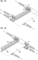
- FIG. 33 is a front, bottom, right side perspective view of the adapter block of FIG. 28 ;
- FIG. 34 is a rear, bottom, left side perspective view of the adapter block of FIG. 28 ;
- FIG. 35 is a top view of the adapter block of FIG. 28 ;
- FIG. 36 is a bottom view of the adapter block of FIG. 28 ;
- FIG. 37 is a front view of the adapter block of FIG. 28 ;
- FIG. 38 is a rear view of the adapter block of FIG. 28 ;
- FIG. 39 is a right side view of the adapter block of FIG. 28 ;
- FIG. 40 is a left side view of the adapter block of FIG. 28 ;
- FIG. 41 is a cross-sectional view taken along line 41 - 41 of FIG. 39 ;
- FIG. 42 illustrates an example of an adapter block similar to that shown in FIGS. 26 - 41 but formed from removable features that are coupled together, the adapter block shown in an exploded configuration and including a connector port arrangement having features that are examples of inventive aspects in accordance with the present disclosure similar to that shown in FIGS. 26 - 41 ;
- FIG. 43 is a front, bottom, right side perspective view of the adapter block of FIG. 42 shown in an exploded configuration
- FIG. 44 is a front, right, top perspective view of an example fiber optic cassette including a connector port arrangement similar to that shown for the adapter blocks of FIGS. 26 - 43 , the connector port arrangement having features that are examples of inventive aspects in accordance with the present disclosure;
- FIG. 45 illustrates the cassette of FIG. 44 with a number of connectors similar to those shown in FIGS. 1 - 22 of the application exploded off the front connector port arrangement and a number of multi-fiber connectors exploded off the rear of the cassette;
- FIG. 46 illustrates the cassette of FIGS. 44 - 45 in a fully exploded configuration
- FIG. 47 is a front, bottom, right side perspective view of the cassette of FIG. 46 shown in a fully exploded configuration
- FIG. 48 is a rear, top, left side perspective view of the cassette of FIGS. 44 - 47 shown in an assembled configuration with the connectors coupled thereto;
- FIG. 49 is a rear, bottom, right side perspective view of the cassette of FIG. 48 ;
- FIG. 50 is a front, top, right side perspective view of the cassette of FIG. 48 ;
- FIG. 51 is a front, top, left side perspective view of the cassette of FIG. 48 ;
- FIG. 52 is a rear, top, right side perspective view of the cassette of FIG. 48 ;
- FIG. 53 is a top view of the cassette of FIG. 48 ;
- FIG. 54 is a bottom view of the cassette of FIG. 48 ;
- FIG. 55 is a front view of the cassette of FIG. 48 ;
- FIG. 57 is a right side view of the cassette of FIG. 48 ;
- FIG. 58 is a left side view of the cassette of FIG. 48 ;
- FIG. 59 is a cross-sectional view taken along line 59 - 59 of FIG. 57 ;
- FIG. 60 is a cross-sectional view taken along line 60 - 60 of FIG. 57 .
- an example connector 10 includes two fiber optic connector portions 12 and a boot 14 .
- Connector portions 12 each include a ferrule 78 for holding a fiber optic cable.
- Connector 10 may also be referred to as duplex connector assembly or duplex connector.
- Connector 10 is matable to an adapter 200 shown in FIGS. 23 - 25 .
- Adapter 200 mates two connectors 10 together or mates another connector to connector 10 for fiber optic signal transmission.
- Each connector portion 12 has a latch 18 including a latch body 20 with a proximal end 22 and a distal end 24 .
- Latch 18 pivots around a connection point 26 during latching and unlatching of latch 18 .
- Latch 18 secures connector 10 to adapter 200 .
- Boot 14 is movable away from connector portions 12 in a longitudinal direction (Direction A in FIG. 2 ) causing pivoting movement of latch 18 about connection point 26 (Direction B in FIG. 2 ). Such pivoting movement allows for unlatching of connector portions 12 from adapter 200 .
- Boot 14 simultaneously moves both latches 18 to allow for connector 10 to be unlatched from a duplex adapter or adapters with side-by-side ports 210 .
- Latch body 20 includes a shoulder 28 which mates with latching shoulder 208 of adapter 200 to secure the connector 10 to the adapter 200 .
- each connector portion 12 defines an LC profile, meaning that the connector portion 12 can mate with an LC adapter.
- Boot 14 includes slots 50 which receive distal ends 24 of latch 18 . Slots 50 and proximal ends 22 are angled so as to cause a lifting motion for proximal ends 22 which results in a downward movement of distal ends 24 of latch 18 when boot 14 is pulled longitudinally away from a remainder of connector 10 . Compare FIGS. 2 and 3 . A user can pull on boot 14 in a longitudinal direction away from the ferrules, and remove the connector 10 from the adapter 200 , without directly engaging latches 18 .
- Connector portion 12 includes a front housing 32 and a ferrule assembly 76 .
- Ferrule assembly 76 includes a ferrule 78 , a hub 80 which holds the ferrule 78 , and a spring 82 which biases hub 80 and ferrule 78 toward front housing 32 .
- a front sleeve 88 and a rear sleeve 90 are mounted together with the ferrule 78 , the hub 80 , and the spring 82 housed inside to form the ferrule assembly 76 .
- An internal tube 84 is provided extending from the hub 80 . Tube 84 prevents epoxy from interfering with the movement of the ferrule 78 , the hub 80 and the spring 82 .
- the rear sleeve 90 is received in holder 96 through a side slot 98 .
- a rear crimp ring 104 and a crimp sleeve 106 allow crimping of a cable 150 to holder 96 .
- a clip 180 may be used to hold connector portions 12 in the desired position as shown in FIG. 1 . If an alternative position of connectors 12 is desired, such as to reverse the polarity of the connector portions 12 , clip 180 is removed, thereby allowing rotation of the front housings 32 with the latches to an opposite side of connector 10 . Such operation is desirable to change the polarity of connector portions 12 with respect to boot 14 . Once the front housings 32 are rotated, clip 180 is repositioned to maintain the front housings 32 in the new desired position.
- Boot 14 includes similar slots 52 on an opposite side of boot 14 so that boot 14 does not need to be rotated.
- Clip 180 can also be provided with different dimensions so as to change the spacing between connector portions 12 , if desired.
- Clip 180 includes outer arms 182 , and an inner arm 184 , and shoulders 186 on each of arms 182 , 184 for securing to front housings 32 of the connector portions 12 .
- front housing 32 mounts to ferrule assembly 76 .
- Ferrule assembly 76 mounts to holder 96 .
- Holder 96 which mounts to two ferrule assemblies 76 , mounts to boot 14 .
- Boot 14 is engageable with latches 18 of the front housings 32 .
- Cable 150 is crimped to holder 96 .
- the individual fibers of cable 150 are fixed to the ferrules 78 , such as with epoxy.
- Cable 150 includes an outer jacket 152 , strength members 154 , typically in the form of an aramid yarn, and two fibers 156 , 158 .
- Each fiber 156 , 158 includes an outer coating 160 and a bare fiber 162 .
- the coating 160 is removed and the bare fiber 162 is inserted into the ferrule 78 , and affixed, such as with epoxy.
- Front housing 32 includes a key 34 for mating with an inner passage 202 of adapter 200 .
- Alignment sleeve 204 aligns the ferrules 78 to mate two connectors 10 .
- Adapter 200 includes two ferrule alignment sleeves 204 , and side-by-side passages 202 for each receiving a connector portion 12 .
- Front housing 32 includes latch 18 on an exterior, and an inner passage 36 in the interior for receiving ferrule assembly 76 .
- Inner passage 36 includes a front shoulder 38 , an inner slot 40 and a side slot 42 .
- Boot 14 includes an opening 54 for mating with structure on holder 96 .
- Boot 14 includes an interior area 56 , and a flexible rear portion 58 .
- Holder 96 includes a tab 100 for mating with structure on rear sleeve 90 of ferrule assembly 76 .
- Holder 96 includes a rear projection 102 for receiving the crimp ring 104 and the crimp sleeve 106 .
- Holder 96 includes cross slots 108 for receiving proximal ends 22 of latch 18 .
- a shoulder 110 mates with opening 54 of boot 14 to allow longitudinal movement of boot 14 relative to holder 96 .
- Side slots 98 lead to oval openings 112 .
- Oval openings 112 allow for lateral movement of connector portions 12 to vary the lateral spacing.
- Oval openings 112 clip over ferrule assemblies 76 to retain the assemblies with holder 96 .
- Front sleeve 88 of ferrule assembly 76 includes a keyed surface 118 for mating with a keyed surface 116 of hub 80 .
- Inner surface 122 of front sleeve 88 is press fit onto outer surface 136 of rear sleeve 90 .
- Rear sleeve 138 defines an inner passage 138 .
- Rear sleeve 90 includes a front collar 124 received in inner slot 40 of front housing 32 .
- Rear collar 126 of rear sleeve 90 is received in slot 114 of holder 96 .
- Outer surface 128 of rear sleeve 90 includes a reduced diameter portion 130 , and a shoulder 132 .
- Reduced diameter portion 130 is received in oval opening 112 .
- Oval opening 112 retains rear sleeve as the side slot 98 is slightly smaller than reduced diameter portion 130 .
- Notch 134 of rear sleeve 90 receives tab 100 of holder 96 .
- Rear sleeve 90 and the rest of ferrule assembly 76 is prevented from rotating relative to holder 96 .
- cable 150 is inserted through boot 14 , crimp ring 104 and crimp sleeve 106 .
- the fibers 156 , 158 are affixed to the ferrules 78 of the ferrule assemblies 76 .
- the ferrule assemblies 76 with the front housings 32 attached are mounted to the holder 96 .
- the cable jacket 152 and strength members 154 are crimped to rear projection 106 between crimp ring 104 and crimp sleeve 106 .
- crimp sleeve 106 is optional is some implementations.
- Boot 14 is pulled over holder 96 until shoulder 110 of holder 96 is retained in opening 54 of boot 14 , and proximal ends 22 of the latches 18 are in one of slots 50 , 52 of boot 14 .
- the front housings 32 are rotated in opposite directions so that the proximal ends 22 of the latches 18 are moved between slots 50 , 52 .
- boot 14 remains mounted to housing 96 .
- Clip 180 is removed during the polarity switching operation.
- Front housings 32 with latches 18 can each be made as a one-piece element.
- Front housing 32 defines an LC profile for mating with ports 210 of adapter 200 .
- front housings 32 are rotatable about the longitudinal axis of each connector portion 12 to change the polarity of the connector 10 , without rotating the ferrule 78 or the ferrule assembly 76 .
- connector 10 includes two fiber optic connector portions 12 and a boot 14 , it is to be appreciated that connector 10 can include a single connector portion 12 .
- clip 180 is not used.
- Clip 180 can be used to provide a certain spacing of connector portions 12 .
- One spacing is sized at 6.25 millimeters. See Dimension D of FIG. 9 .
- Another spacing that may be used is 5.25 millimeters. See Dimension C of FIG. 9 .
- a different clip 180 with a different spacing may be used, or the clip may be not used for the closer spacing.
- Boot 14 is shown as including a spring return feature.
- Pocket 140 of holder 96 receives a spring holder 142 including a peg 144 .
- Spring holder 142 with peg 144 holds a return spring 146 .
- Spring 146 biases boot 14 toward the forward position of FIG. 2 when released by the user. When the user pulls boot 14 longitudinally away from the connector portions 12 , the spring 146 is compressed. Spring 146 moves the boot 14 back to the rest position of FIG. 2 upon release by the user.
- Pocket 140 of holder 96 is accessible through opening 148 .
- FIGS. 26 - 41 an example of another fiber optic adapter 300 that is configured for mating connectors similar to the connectors 10 of FIGS. 1 - 22 described above is illustrated.
- the depicted fiber optic adapter 300 is a dual layer adapter and provides a connector port arrangement 302 including at least one upper port or receptacle 304 and at least one lower port or receptacle 306 vertically aligned with the upper receptacle 304 to form a column 308 of receptacles.
- the column 308 includes a center divider 310 that divides the at least one upper receptacle 304 from the at least one lower receptacle 306 .
- the dual layer adapter 300 is provided in the form of an adapter block comprising a plurality of the columns 308 of vertically aligned upper and lower receptacles 304 , 306 .
- the adapter block 300 is provided as a unitarily molded structure wherein all of the receptacles 304 , 306 and the center divider 310 are formed as an integral unit, wherein ferrule alignment sleeves 312 may be inserted therein.
- each adapter of the block 300 may define a ferrule alignment structure 314 located within an axial cavity extending through each adapter.
- the ferrule alignment structure 314 includes a sleeve mount 316 defining an axial bore 318 for receiving a ferrule alignment sleeve 312 .
- the sleeve 312 may be inserted axially into the sleeve mount 316 after the block 300 has been molded.
- the sleeve 312 may be inserted into the bore 318 from either end before welding the two adapter block halves together. It should be noted that in such examples, the front and rear halves may also be coupled together via other methods such as with snap-fit interlocking instead of ultrasonic welding.
- the adapter block 300 defines twenty-four individual ports or receptacles, wherein twelve receptacles 306 are provided on a lower level 322 and twelve receptacles 304 are provided at an upper level 320 . It should be noted that the twelve receptacles provided on each level 320 , 322 may be grouped in duplex pairs and the adapter block 300 may be deemed to contain six duplex adapters on each level 320 , 322 . Other numbers of receptacles are possible depending upon the connectivity need.
- the center divider 310 is integrally molded into the adapter block 300 .
- the adapter block 300 is able to increase connection density.
- the adapter block 300 may define a height H of about 0.75 inches. It should be noted that the height H of 0.75 inches is configured to accommodate connectors 10 such as those described above with respect to FIGS. 1 - 22 that have latches 18 which can be unlocked by longitudinally-movable boots 14 .
- the divider 310 may be provided with a slightly wider profile, with the height H of the adapter block 300 being less than about 0.875 inches. It should be understood that the adapter block 300 may be modified for different types of fiber optic connector formats.
- the shared center divider 310 between the upper level 320 and the lower level 322 of receptacles provides the ability to increase the density of the adapter block 300 to levels not found in prior fiber optic adapters.
- the center divider 310 includes or defines at least a portion of the latching structures 324 , specifically latching shoulders 326 , for both an upper receptacle 304 and a lower receptacle 306 for each given column 308 of the receptacles.
- the shoulders 28 defined on the latches 18 of connectors 10 similar to those described above with respect to FIGS. 1 - 22 mate with the latching shoulders 326 of the upper and lower adapter receptacles 304 , 306 to secure the connectors 10 to the adapters 300 .
- the adapter block 300 is configured such that when the connectors 10 are mated to the adapter ports within a given column 308 , the latch body 20 of a connector 10 coupled at the lower level 322 faces toward the latch body 20 of a connector 10 coupled at the upper level 320 .
- the front housings 32 thereof may include a key 34 for mating with an inner passage of adapters 300 .
- Alignment sleeve 312 within each adapter 300 aligns the ferrules 78 to mate two such connectors 10 .
- each adapter of the adapter block 300 includes a ferrule alignment sleeve 312 for receiving and mating two connectors 10 .
- the boot 14 of each connector 10 may include slots 50 , 52 which receive distal ends 24 of latch 18 .
- Slots 50 , 52 and proximal ends 22 are angled so as to cause a lifting motion for proximal ends 22 which results in a downward movement of distal ends 24 of latch 18 when boot 14 is pulled longitudinally away from a remainder of connector 10 .
- a user can pull on boot 14 in a longitudinal direction away from the ferrules 78 , and remove a connector 10 from the adapter ports 304 , 306 , without directly engaging latches 18 .
- the connector port arrangement 302 shown in FIGS. 26 - 41 is part of a fiber optic adapter 300 defining ports at both a front end 328 and a rear end 330 for optically mating fiber optic connectors 10 .
- Each fiber optic adapter of the block 300 of FIGS. 26 - 41 defines symmetric ports at both the front and rear ends 328 , 330 of the adapter 300 for mating similar fiber optic connectors 10 .
- the fiber optic adapters 300 may define dissimilar ports at the front and rear ends 328 , 330 for mating two different types of connectors.
- FIGS. 42 - 43 illustrate another possible embodiment for forming an adapter 400 .
- the adapter 400 is depicted as being formed from a center structure 402 that is captured between top and bottom covers 404 , 406 .
- the center structure 402 and the top and bottom covers 404 , 406 may include intermating keys 408 and slots 410 for orientation/alignment purposes.
- the adapter embodiment 400 shown in FIGS. 42 - 43 may also be ultrasonically welded or coupled with snap interlocks once the parts 402 , 404 , 406 have been fit together.
- the connector port arrangement 302 discussed above may be provided as part of a fiber optic cassette 500 .
- the connector port arrangement 302 may be part of a front panel 502 of the cassette 500 , as shown in FIGS. 44 - 60 , wherein the front panel 502 defines upper and lower receptacles 504 , 506 and a shared center divider 508 , similar to the adapter blocks 300 , 400 of FIGS. 26 - 43 .
- the cassette 500 may be formed from multiple parts that are snapped together to form the cassette 500 .
- the cassette defines a cassette body 510 having a base 512 and a cover 514 that is configured to be snap-fit to the base to capture a center structure 516 .
- the center structure 516 defines the front panel 502 .
- the center structure 516 may be oriented/aligned with respect to the base 512 (and the cover 514 ) with intermating keys 518 and slots 520 and also fixed with respect to the base 512 (and the cover 514 ) with flexible fingers 522 .
- the center structure 516 once in place, is captured between the base 512 and the cover 514 .
- the cassette body 510 forms a closed interior 524 for routing fibers therein between a front end 526 defined by the cassette body 510 and a rear end 528 defined by the cassette body 510 .
- the front connection panel 502 defined by the center structure 516 is provided at the front end 526 .
- the rear end 528 of the cassette body 510 includes connector ports 530 for receiving connectors 532 (e.g., multi-fiber connectors) carrying fibers to be relayed to the front panel 502 with terminated connectors as will be described in further detail.
- connectors 532 e.g., multi-fiber connectors
- the front panel 502 may be integrally molded to parts of the cassette body 510 such as the base 512 or the cover 514 .
- the depicted fiber optic cassette 500 is configured to provide a connection point at the front end 526 utilizing the connectors 10 described above with respect to FIGS. 1 - 22 .
- the cassette 500 may include the multi-fiber type connectors 532 , wherein fibers entering the cassette 500 via the multi-fiber connectors 532 are separated out and relayed to the front panel 502 within the body 510 of the cassette 500 .
- the fibers may simply be separated out and relayed to the front panel 502 in a signal flow-through design that provides for a format-switching cassette 500 , wherein the format may be changed from a multi-fiber connector 532 to individual simplex or duplex connectors 10 such as those shown in FIGS.
- the fibers may be provided as loose fibers within the body 510 of the cassette 500 or may be provided as part of a flexible circuit utilizing a flexible substrate that fixes the fibers as they are relayed from the rear connectors 532 to the front panel 502 .
- the fibers within the cassette 500 may be processed via optical devices such as fan-outs, splitters, multiplexers, filters, couplers, etc. before being relayed to the front panel 502 for connection.
- the center structure 516 and the front panel 502 defined thereby may be configured such that, while the external receptacles 504 , 506 are configured for receiving standard fiber optic connectors 10 , an internal side 534 of the panel 502 is configured with non-standard adapter receptacles 536 such as those shown and described in U.S. Pat. Nos. 9,535,229; 9,488,788; and 9,223,094, the disclosures of which are incorporated herein in their entireties.
- the fibers within the interior 524 of the cassette 500 extending from the rear connectors 532 to the front panel 502 may be terminated with non-conventional connectors that are coupled to the internal side 534 of the front panel 502 .
- non-conventional connectors may mate with standard format fiber optic connectors 10 coupled to the upper and lower receptacles 504 , 506 of the front connection panel 502 , coming from an exterior of the cassette 500 .
- each adapter may still include a standard alignment sleeve therewithin for aligning the ferrules of the mated connectors.
- the front panel 502 of the cassette 500 may be provided with a full adapter block configuration that mates standard fiber optic connectors 10 from both the external side and the internal side.
- the separated out fibers coming from the multi-fiber connectors 532 would be terminated with standard type fiber optic connectors 10 that are coupled to the internal side 534 of the front panel 502 .
- a fiber optic cassette 500 has been shown to include a connection panel 502 that is configured to mate external standard connectors and internal non-conventional connectors, such an arrangement may be provided in the adapter blocks 300 , 400 discussed above with respect to FIGS. 26 - 43 .
- Such an adapter block 300 , 400 may be provided as a stand-alone structure or be mounted in a removable manner to different optical devices such as fiber optic cassettes for defining the front panels of such cassettes, as discussed above.
Abstract
Description
Claims (15)
Priority Applications (1)
| Application Number | Priority Date | Filing Date | Title |
|---|---|---|---|
| US17/563,628 US11650378B2 (en) | 2017-06-07 | 2021-12-28 | Fiber optic adapter and cassette |
Applications Claiming Priority (4)
| Application Number | Priority Date | Filing Date | Title |
|---|---|---|---|
| US201762516201P | 2017-06-07 | 2017-06-07 | |
| PCT/US2018/036466 WO2018226959A1 (en) | 2017-06-07 | 2018-06-07 | Fiber optic adapter and cassette |
| US201916620103A | 2019-12-06 | 2019-12-06 | |
| US17/563,628 US11650378B2 (en) | 2017-06-07 | 2021-12-28 | Fiber optic adapter and cassette |
Related Parent Applications (2)
| Application Number | Title | Priority Date | Filing Date |
|---|---|---|---|
| US16/620,103 Continuation US11215767B2 (en) | 2017-06-07 | 2018-06-07 | Fiber optic adapter and cassette |
| PCT/US2018/036466 Continuation WO2018226959A1 (en) | 2017-06-07 | 2018-06-07 | Fiber optic adapter and cassette |
Publications (2)
| Publication Number | Publication Date |
|---|---|
| US20220120980A1 US20220120980A1 (en) | 2022-04-21 |
| US11650378B2 true US11650378B2 (en) | 2023-05-16 |
Family
ID=64566033
Family Applications (2)
| Application Number | Title | Priority Date | Filing Date |
|---|---|---|---|
| US16/620,103 Active 2038-10-01 US11215767B2 (en) | 2017-06-07 | 2018-06-07 | Fiber optic adapter and cassette |
| US17/563,628 Active US11650378B2 (en) | 2017-06-07 | 2021-12-28 | Fiber optic adapter and cassette |
Family Applications Before (1)
| Application Number | Title | Priority Date | Filing Date |
|---|---|---|---|
| US16/620,103 Active 2038-10-01 US11215767B2 (en) | 2017-06-07 | 2018-06-07 | Fiber optic adapter and cassette |
Country Status (2)
| Country | Link |
|---|---|
| US (2) | US11215767B2 (en) |
| WO (1) | WO2018226959A1 (en) |
Families Citing this family (7)
| Publication number | Priority date | Publication date | Assignee | Title |
|---|---|---|---|---|
| WO2018226959A1 (en) * | 2017-06-07 | 2018-12-13 | Commscope Technologies Llc | Fiber optic adapter and cassette |
| US10830963B2 (en) | 2017-11-17 | 2020-11-10 | Commscope Technologies Llc | Fiber optic connector locking feature |
| US11573381B2 (en) | 2020-03-27 | 2023-02-07 | Afl Telecommunications Llc | Optical fiber connectors and methods of connecting optical fibers |
| US11409056B2 (en) | 2020-03-27 | 2022-08-09 | Afl Ig Llc | Optical fiber connectors and methods of connecting optical fibers |
| WO2022178017A1 (en) * | 2021-02-19 | 2022-08-25 | Commscope Technologies Llc | Low-profile telecommunications connectors |
| US20230050053A1 (en) * | 2021-08-16 | 2023-02-16 | Nest Technical Services, Inc. | Interstitial recessed cantilever latch mechanism for fiber optic and electrical connectors |
| CN116338882A (en) * | 2021-10-09 | 2023-06-27 | 华为技术有限公司 | Connection box |
Citations (322)
| Publication number | Priority date | Publication date | Assignee | Title |
|---|---|---|---|---|
| US2805106A (en) | 1954-12-27 | 1957-09-03 | Metal Trim Ltd | Double extension slides |
| US2864656A (en) | 1954-06-25 | 1958-12-16 | Yorinks Alexander | Slide mechanism |
| US3901564A (en) | 1973-10-29 | 1975-08-26 | Henry P Armstrong | Drawer extensible slide chassis |
| US4070076A (en) | 1977-05-05 | 1978-01-24 | The Raymond Lee Organization, Inc. | Drawer sliding device |
| DE2735106A1 (en) | 1977-08-04 | 1979-02-15 | Licentia Gmbh | Telecommunications cable fitting arrangement - uses fibre=optics conductors together with copper core conductors in one cable |
| US4172625A (en) | 1977-12-15 | 1979-10-30 | Comerco, Inc. | Drawer extenders |
| DE2918309A1 (en) | 1979-05-07 | 1980-11-13 | Schulz Kunststoff Heino | Guide rail assembly for drawer - consists of outer, central and drawer rail with pinion and toothed rack |
| US4320934A (en) | 1978-06-13 | 1982-03-23 | Julius Blum Gesellschaft M.B.H. | Pull-out guide for drawers |
| US4359262A (en) | 1980-06-30 | 1982-11-16 | Northern Telecom Limited | Tray for organizing optical fiber splices and enclosures embodying such trays |
| US4373776A (en) | 1980-06-30 | 1983-02-15 | Northern Telecom Limited | Protection case for optical fiber splices |
| FR2531576A1 (en) | 1982-08-04 | 1984-02-10 | Cit Alcatel | Optoelectronic connecting and interface frame. |
| JPS5974523A (en) | 1982-10-21 | 1984-04-27 | Furukawa Electric Co Ltd:The | Optical fiber connection box |
| DE3308682A1 (en) | 1983-03-11 | 1984-09-20 | Krone Gmbh, 1000 Berlin | Matrix main distribution frame |
| US4494806A (en) | 1983-05-13 | 1985-01-22 | Leslie Metal Arts Company | Spring loaded drawer assembly with mechanical damping |
| US4502754A (en) | 1982-01-19 | 1985-03-05 | Nippon Electric Co., Ltd. | Optical fiber interconnection mechanism |
| EP0146478A2 (en) | 1983-12-20 | 1985-06-26 | Lignes Telegraphiques Et Telephoniques L.T.T. | Joining apparatus for cables, especially optical fibres |
| EP0149250A2 (en) | 1983-12-30 | 1985-07-24 | Wilhelm Sedlbauer GmbH Fabrik für Feinmechanik und Elektronik | Distribution mounting for the end parts of glassfibre cables |
| JPS60169811A (en) | 1984-02-14 | 1985-09-03 | Furukawa Electric Co Ltd:The | Containing device for connection excessive length of optical fiber |
| AU4099585A (en) | 1984-04-11 | 1985-10-17 | N.V. Raychem S.A. | Splice case for optical fibre cable |
| JPS6155607A (en) | 1984-08-28 | 1986-03-20 | Fujitsu Ltd | Light distributing board |
| US4585303A (en) | 1982-08-04 | 1986-04-29 | Compagnie Industrielle Des Telecommunication Cit-Alcatel | Optical cable header |
| JPS6190104A (en) | 1984-10-09 | 1986-05-08 | Nec Corp | Installing structure for optical adapter |
| US4595255A (en) | 1983-08-24 | 1986-06-17 | Fiberlan, Inc. | Optical fiber wiring center |
| AU5531486A (en) | 1985-03-29 | 1986-10-02 | Siemens Aktiengesellschaft | Coupling rack for glassfibre cables |
| US4630886A (en) | 1984-04-16 | 1986-12-23 | At&T Bell Laboratories | Lightguide distributing unit |
| FR2587127A1 (en) | 1985-09-06 | 1987-03-13 | Valleix Paul | STRUCTURE FOR OPTICAL CONNECTIONS |
| US4697874A (en) | 1984-12-14 | 1987-10-06 | Nozick Jacques E | Distribution frame for optical cables |
| US4699455A (en) | 1985-02-19 | 1987-10-13 | Allen-Bradley Company | Fiber optic connector |
| US4708430A (en) | 1984-10-25 | 1987-11-24 | Northern Telecom Limited | Cabinet for optical cable terminating equipment |
| US4717231A (en) | 1983-01-05 | 1988-01-05 | Vincent Dewez | Interconnecting and distributing box for optical fibers |
| US4737039A (en) | 1986-12-08 | 1988-04-12 | Knape & Vogt Manufacturing Company | Drawer rail carrier roller mount |
| JPS63184271A (en) | 1987-01-27 | 1988-07-29 | 松下電工株式会社 | Modular plug |
| US4765710A (en) | 1985-07-30 | 1988-08-23 | Siemens Aktiengesellschaft | Distributing frame for optical waveguides and the like |
| US4792203A (en) | 1985-09-17 | 1988-12-20 | Adc Telecommunications, Inc. | Optical fiber distribution apparatus |
| US4820007A (en) | 1988-02-12 | 1989-04-11 | American Telephone And Telegraph Company At&T Bell Laboratories | Cable closure and methods of assembling |
| US4840449A (en) | 1988-01-27 | 1989-06-20 | American Telephone And Telegraph Company, At&T Bell Laboratories | Optical fiber splice organizer |
| US4898448A (en) | 1988-05-02 | 1990-02-06 | Gte Products Corporation | Fiber distribution panel |
| EP0356942A2 (en) | 1988-08-29 | 1990-03-07 | Gte Control Devices Of Puerto Rico Incorporated | 1550NM fiber distribution panel |
| DE3836273A1 (en) | 1988-10-25 | 1990-04-26 | Standard Praezision Gmbh | Synchronised three-membered telescopic rail for draw-out members |
| US4971421A (en) | 1989-09-29 | 1990-11-20 | Reliance Comm/Tec Corporation | Fiber optic splice and patch enclosure |
| EP0406151A2 (en) | 1989-06-29 | 1991-01-02 | Adc Telecommunications, Inc. | Optical fiber storage container |
| US4986762A (en) | 1989-08-15 | 1991-01-22 | Minnesota Mining And Manufacturing Company | Termination module for use in an array of modules |
| US4995688A (en) | 1989-07-31 | 1991-02-26 | Adc Telecommunications, Inc. | Optical fiber distribution frame |
| US5011424A (en) | 1989-11-01 | 1991-04-30 | Amp Incorporated | Latch mechanism for electrical connector |
| US5024498A (en) | 1988-11-12 | 1991-06-18 | U.S. Philips Corp. | Switch box for producing freely selectable optical plug connections |
| WO1991010927A1 (en) | 1990-01-22 | 1991-07-25 | Porta Systems Corp. | Optical fiber cable distribution frame and support |
| US5066149A (en) | 1990-09-11 | 1991-11-19 | Adc Telecommunications, Inc. | Splice tray with slack take-up |
| US5067678A (en) | 1989-07-31 | 1991-11-26 | Adc Telecommunications, Inc. | Optic cable management system |
| US5071211A (en) | 1988-12-20 | 1991-12-10 | Northern Telecom Limited | Connector holders and distribution frame and connector holder assemblies for optical cable |
| EP0464570A1 (en) | 1990-06-29 | 1992-01-08 | Alcatel Cit | Modular device for storing reserves of transmission means in a transmission line, notably fibre optic |
| US5090916A (en) | 1990-07-11 | 1992-02-25 | Interconnection Informatique | Male connector for telephone and/or data processing communications network |
| EP0479226A1 (en) | 1990-10-04 | 1992-04-08 | MARS-ACTEL Société Anonyme dite: | Cassette for optical junction |
| US5123071A (en) | 1990-03-09 | 1992-06-16 | Amp Incorporated | Overconnector assembly for a pair of push-pull coupling type optical fiber connectors |
| US5127082A (en) | 1991-03-22 | 1992-06-30 | The Siemon Company | Fiber optic patch panel |
| US5129030A (en) | 1991-05-30 | 1992-07-07 | At&T Bell Laboratories | Movable lightguide connector panel |
| US5138688A (en) | 1990-11-09 | 1992-08-11 | Northern Telecom Limited | Optical connector holder assembly |
| US5142606A (en) | 1990-01-22 | 1992-08-25 | Porta Systems Corp. | Optical fiber cable distribution frame and support |
| US5142607A (en) | 1990-03-20 | 1992-08-25 | Rittal-Werk Rudolf Loh Gmbh & Co. Kg | Splice box for optical wave guide |
| US5167001A (en) | 1991-09-03 | 1992-11-24 | Northern Telecom Limited | Optical fiber storage and connector tray and shelf and tray assembly |
| FR2678076A1 (en) | 1991-06-20 | 1992-12-24 | Cit Alcatel | Module for storing a transmission support reserve on a link, especially a fibre-optic link, and storage device including a set of such modules |
| US5174675A (en) | 1990-05-07 | 1992-12-29 | Inventio Ag | Guide bar for an elevator door |
| EP0538164A1 (en) | 1991-10-15 | 1993-04-21 | France Telecom | Distribution head for high capacity optical cables |
| US5211572A (en) | 1992-06-23 | 1993-05-18 | Molex Incorporated | Security locking key mechanism for electrical connectors |
| US5240209A (en) | 1992-11-17 | 1993-08-31 | Telect, Inc. | Telecommunication multiple cable carrier |
| US5247603A (en) | 1992-01-24 | 1993-09-21 | Minnesota Mining And Manufacturing Company | Fiber optic connection system with exchangeable cross-connect and interconnect cards |
| US5275064A (en) | 1992-06-12 | 1994-01-04 | General Devices Co., Inc. | Extensible platform with cable drive system |
| US5285515A (en) | 1992-02-21 | 1994-02-08 | Mars Actel | Adaptable cassette for coiling and splicing optical fibers |
| US5289558A (en) | 1991-10-05 | 1994-02-22 | Krone Aktiengesellshaft | Switching assembly for glass fiber cables of the telecommunication and data technology |
| US5315679A (en) | 1992-04-27 | 1994-05-24 | International Business Machines Corporation | Optical fibers duplex connector assembly |
| US5316243A (en) | 1989-07-31 | 1994-05-31 | Adc Telecommunications, Inc. | Optic cable management |
| US5323480A (en) | 1992-11-25 | 1994-06-21 | Raychem Corporation | Fiber optic splice closure |
| US5335349A (en) | 1992-12-14 | 1994-08-02 | Telect, Inc. | Telecommunication overhead cable distribution assembly |
| US5335301A (en) | 1993-05-05 | 1994-08-02 | Methode Electronics, Inc. | Fiber optic connector with sliding key |
| US5339379A (en) | 1993-06-18 | 1994-08-16 | Telect, Inc. | Telecommunication fiber optic cable distribution apparatus |
| US5353367A (en) | 1993-11-29 | 1994-10-04 | Northern Telecom Limited | Distribution frame and optical connector holder combination |
| US5363466A (en) | 1992-02-21 | 1994-11-08 | Mars Actel | Assembly of hinged flat modules |
| US5363467A (en) | 1993-05-28 | 1994-11-08 | Minnesota Mining And Manufacturing Company | Compact fiber optic housing |
| WO1995007480A1 (en) | 1993-09-08 | 1995-03-16 | N.V. Raychem S.A. | Organization of optical fibres |
| US5402515A (en) | 1994-03-01 | 1995-03-28 | Minnesota Mining And Manufacturing Company | Fiber distribution frame system, cabinets, trays and fiber optic connector couplings |
| US5412751A (en) | 1993-08-31 | 1995-05-02 | The Siemon Company | Retrofittable multimedia patch management system |
| DE4413136C1 (en) | 1994-04-19 | 1995-05-04 | Loh Kg Rittal Werk | Optical-fibre splice box |
| US5438641A (en) | 1993-03-26 | 1995-08-01 | Corning Incorporated | Optical fiber component cassette with pigtail tube assembly |
| US5462457A (en) | 1994-09-22 | 1995-10-31 | The Whitaker Corporation | Overmold strain relief and snag prevention feature |
| US5481634A (en) | 1994-06-24 | 1996-01-02 | At&T Corp. | Connector for optical fiber |
| US5490229A (en) | 1993-12-08 | 1996-02-06 | At&T Ipm Corp. | Slidably mounted optical fiber distribution tray |
| US5497444A (en) | 1994-01-21 | 1996-03-05 | Adc Telecommunications, Inc. | High-density fiber distribution frame |
| DE29504191U1 (en) | 1995-03-01 | 1996-03-28 | Krone Ag | Insert for receiving devices of the LWL technology |
| WO1996010203A1 (en) | 1994-09-28 | 1996-04-04 | Telephone Cables Limited | A splice tray |
| US5509096A (en) | 1994-10-28 | 1996-04-16 | Syntec Inc. | Receptacle and plug fiber optic connector assembly |
| US5511144A (en) | 1994-06-13 | 1996-04-23 | Siecor Corporation | Optical distribution frame |
| US5530783A (en) | 1994-08-31 | 1996-06-25 | Berg Technology, Inc. | Backplane optical fiber connector for engaging boards of different thicknesses and method of use |
| US5570450A (en) | 1991-12-12 | 1996-10-29 | Telefonica De Espana, S.A. | Junction and modular optical sharing terminal assembly |
| US5574812A (en) | 1993-01-26 | 1996-11-12 | Siemens Aktiengesellscnaft | Holder arrangement for optical connectors or the like |
| US5579425A (en) | 1995-08-30 | 1996-11-26 | Lucent Technologies Inc. | Anti-snag duplex connector |
| US5613030A (en) | 1995-05-15 | 1997-03-18 | The Whitaker Corporation | High density fiber optic interconnection enclosure |
| US5638474A (en) | 1995-08-30 | 1997-06-10 | Lucent Technologies Inc. | Anti-snag latch assembly for a connector |
| US5640481A (en) | 1994-08-15 | 1997-06-17 | Pirelli General Plc | Guiding optical fibres |
| US5651690A (en) | 1995-08-30 | 1997-07-29 | Hubbell Incorporated | Electrical connector adapter |
| US5655044A (en) | 1994-12-01 | 1997-08-05 | Siemens Aktiengesellschaft | Cassette module having swingable cassettes and a backplane with guide ridges for guiding light waveguides and optical fibers |
| US5675682A (en) | 1995-02-21 | 1997-10-07 | Diamond Sa | Plug arrangement comprising at least two optical plugs |
| US5724469A (en) | 1996-01-26 | 1998-03-03 | Ortronics, Inc. | Adjustable fiber storage plate |
| US5802237A (en) | 1997-04-18 | 1998-09-01 | Minnesota Mining And Manufacturing Company | Optical fiber organizer |
| US5811055A (en) | 1996-02-06 | 1998-09-22 | Geiger; Michael B. | Torch mounted gas scavaging system for manual and robotic welding and cutting torches |
| US5836148A (en) | 1996-02-06 | 1998-11-17 | Kunimorikagaku Ltd. | Cable chain |
| WO1999000619A1 (en) | 1997-06-26 | 1999-01-07 | Crane Nuclear, Inc. | Method and apparatus for on-line detection of leaky emergency shut down or other valves |
| US5882100A (en) | 1996-10-07 | 1999-03-16 | Julius Blum Gesellschaft M.B.H. | Pull out guide assembly for drawers and the like |
| US5887106A (en) | 1996-04-12 | 1999-03-23 | Telephone Cables Limited | Management of optical fiber |
| US5917984A (en) | 1996-03-14 | 1999-06-29 | Krone Aktiengesellschaft | Management-capable splice cassette |
| US5923753A (en) | 1997-11-17 | 1999-07-13 | Adc Telecommunications, Inc. | Optic cable exit trough with bypass |
| US5946440A (en) | 1997-11-17 | 1999-08-31 | Adc Telecommunications, Inc. | Optical fiber cable management device |
| US5966492A (en) | 1997-12-19 | 1999-10-12 | Antec Corporation | Apparatus for storing and splicing optical fibers |
| EP0563995B1 (en) | 1992-04-03 | 1999-10-13 | The Whitaker Corporation | Optical fiber connector |
| US5971626A (en) | 1997-08-29 | 1999-10-26 | Siecor Corporation | Fiber optic connector and connector sleeve assembly |
| US5975769A (en) | 1997-07-08 | 1999-11-02 | Telect, Inc. | Universal fiber optic module system |
| US5978540A (en) | 1998-04-23 | 1999-11-02 | Antec Corporation | Apparatus for interconnecting optical fibers |
| US6009224A (en) | 1997-11-06 | 1999-12-28 | Allen; Barry Wayne | Fiber optic organizer with lockable trays and method of accessing a tray |
| US6022150A (en) | 1997-04-30 | 2000-02-08 | The Whitaker Corporation | Fiber optic connector |
| US6024498A (en) | 1998-02-05 | 2000-02-15 | Lucent Technologies Inc. | Optical fiber connector assembly |
| US6027252A (en) | 1997-12-19 | 2000-02-22 | The Whitaker Corporation | Simplified fiber optic receptacle |
| US6044194A (en) | 1997-03-17 | 2000-03-28 | Tii-Ditel, Inc. | Fiber optic cable bend radius control |
| US6076908A (en) | 1998-09-17 | 2000-06-20 | Platt And Labonia Co. | Drawer for storage cabinet |
| US6076974A (en) | 1998-09-14 | 2000-06-20 | Lucent Technologies Inc. | Optical fiber connector |
| US6196733B1 (en) | 1999-06-08 | 2001-03-06 | Lucent Technologies Inc. | Strain relief apparatus for optical connector |
| US6215938B1 (en) | 1998-09-21 | 2001-04-10 | Adc Telecommunications, Inc. | Fiber optic cabinet and tray |
| US6226436B1 (en) | 1999-11-18 | 2001-05-01 | Lucent Technologies, Inc. | Fiber optical pedestal |
| US20010001270A1 (en) | 1998-07-21 | 2001-05-17 | Adc Telecommunications, Inc. | Fiber optic module |
| US6236795B1 (en) | 1999-06-07 | 2001-05-22 | E. Walter Rodgers | High-density fiber optic cable distribution frame |
| US6250817B1 (en) | 1999-10-19 | 2001-06-26 | Lucent Technologies Inc. | Device that attaches to the boot of an optical fiber simplex connector to provide the connector with anti-snagging and/or polarity identification features |
| US6250942B1 (en) | 1999-08-30 | 2001-06-26 | Berg Technology, Inc. | Electrical connector with combined shield and latch |
| US6254418B1 (en) | 2000-08-16 | 2001-07-03 | The Jpm Company | Latch release |
| US6269214B1 (en) | 1998-08-04 | 2001-07-31 | Pouyet, S.A. | Device for interconnecting optical fiber cables |
| US6276839B1 (en) | 1997-11-13 | 2001-08-21 | Diamond Sa | Plug arrangement for an optical insert rack plug connection |
| US6301424B1 (en) | 2000-04-13 | 2001-10-09 | Lucent Technologies Inc. | Distribution frame cable routing apparatus |
| US6325547B1 (en) | 1999-10-06 | 2001-12-04 | Lucent Technologies Inc. | Optical connector having a housing assembly that is comprised of polyphenylsulfone |
| US20020028055A1 (en) | 2000-09-06 | 2002-03-07 | Michitomo Shibutani | Optical cable adapter or connector |
| US6360050B1 (en) | 2000-09-08 | 2002-03-19 | Telect, Inc. | High density fiber distribution tray system |
| US6357934B1 (en) | 2000-01-27 | 2002-03-19 | Lucent Technologies Inc. | Optical fiber boot for a connector that provides anti-snagging and polarity identification |
| US20020090177A1 (en) | 2001-01-10 | 2002-07-11 | Anderson Jerry Max | Duplex optical connector |
| US6438310B1 (en) | 2000-01-24 | 2002-08-20 | Adc Telecommunications, Inc. | Cable management panel with sliding drawer |
| US6435732B1 (en) | 2000-09-28 | 2002-08-20 | Sumitomo Wiring Systems, Ltd. | Optical connector |
| US6439523B1 (en) | 2000-06-02 | 2002-08-27 | Panduit Corp. | Universal mounting system for a fiber optic management center |
| US6447170B1 (en) | 1999-06-29 | 2002-09-10 | Nec Tokin Corporation | Locking and unlocking mechanism of cable connector and method for locking and unlocking |
| CN2513249Y (en) | 2001-06-25 | 2002-09-25 | 富士康(昆山)电脑接插件有限公司 | Electric connector |
| US20020166226A1 (en) | 2001-05-14 | 2002-11-14 | Dainippon Screen Mfg. Co., Ltd. | Conductor connecting apparatus |
| US20020181922A1 (en) | 2001-06-01 | 2002-12-05 | Xin Xin | High density fiber optic splitter/connector tray system |
| US6496638B1 (en) | 1998-10-23 | 2002-12-17 | Lucent Technologies Inc. | Optical fiber cassette |
| US20030002808A1 (en) | 2000-12-27 | 2003-01-02 | Lampert Norman R. | Optical connector receptacle having switching capability |
| US6504988B1 (en) | 2000-01-24 | 2003-01-07 | Adc Telecommunications, Inc. | Cable management panel with sliding drawer |
| US20030007767A1 (en) | 2001-07-06 | 2003-01-09 | Douglas Joel B. | Cable management panel with sliding drawer and methods |
| US20030017729A1 (en) | 2001-07-20 | 2003-01-23 | Wayne Huang | Electrical connector having device for controlled latching movement |
| US6591051B2 (en) | 2001-11-16 | 2003-07-08 | Adc Telecommunications, Inc. | Fiber termination block with angled slide |
| US20030128951A1 (en) | 2001-11-13 | 2003-07-10 | Didier Lecomte | Optical fiber connection and distribution module intended for use in an optical distribution frame |
| US6594434B1 (en) | 2001-10-26 | 2003-07-15 | Ciena Corporation | Fiber optic cables management and measurement apparatus |
| US6600866B2 (en) | 2001-03-13 | 2003-07-29 | 3M Innovative Properties Company | Filament organizer |
| JP2003224373A (en) | 2002-01-29 | 2003-08-08 | Nec Commun Syst Ltd | Chassis for electronic equipment |
| JP2003526116A (en) | 1999-03-09 | 2003-09-02 | ザ リージェンツ オブ ザ ユニヴァーシティ オブ カリフォルニア | Method and apparatus for cantilevered microstructure |
| US20030174996A1 (en) | 2002-03-15 | 2003-09-18 | Fiber Optic Network Solutions, Inc. | Optical fiber enclosure system using integrated optical connector and coupler assembly |
| US20030190035A1 (en) | 2002-04-05 | 2003-10-09 | Knudsen Clinton M. | Termination frame with modules and method |
| US20030220082A1 (en) | 2002-05-21 | 2003-11-27 | Nec Corporation | Path timing detection method, path timing detection apparatus, and adaptive array antenna system |
| US20030220087A1 (en) | 2002-05-27 | 2003-11-27 | Nokia Corporation | Circuit arrangement for phase locked loop, and phase locked loop based method to be used in cellular network terminals |
| US20030220086A1 (en) | 2002-05-23 | 2003-11-27 | Icefyre Semiconductor Corporation | Oscillator frequency offsets |
| US20030220089A1 (en) | 2002-05-23 | 2003-11-27 | Chang Tsung Yuan | Method and circuit to reduce intermodulation distortion |
| US20030220083A1 (en) | 2002-05-27 | 2003-11-27 | Samsung Electro-Mechanics Co., Ltd. | High frequency composite component |
| US20030220081A1 (en) | 2002-05-23 | 2003-11-27 | Jeffrey A. Dykstra | Transceiver circuit arrangement and method |
| US20030220008A1 (en) | 2002-04-26 | 2003-11-27 | Mark Viklund | Axial latch actuator |
| US20030220088A1 (en) | 2002-03-12 | 2003-11-27 | Cowley Nicholas Paul | Tuner |
| US20030220084A1 (en) | 2002-05-22 | 2003-11-27 | Stmicroelectronics., Inc. | Frequency offset estimator |
| US20030220085A1 (en) | 2002-03-27 | 2003-11-27 | Charbel Khawand | Method for maintaining automatic gain control settings for a multi-frequency communication device |
| US20030220080A1 (en) | 2002-05-27 | 2003-11-27 | Alcatel | Optimized method of transmitting multimedia content |
| US20030222008A1 (en) | 2002-05-28 | 2003-12-04 | Scott Nightlinger | Countertop water treatment unit |
| KR200337929Y1 (en) | 2003-10-23 | 2004-01-13 | 허필규 | A Housing for purchase of optical fiber adapter |
| US6677520B1 (en) | 2002-07-22 | 2004-01-13 | Adc Telecommunications, Inc. | Fanning tray |
| US20040013390A1 (en) | 2002-07-22 | 2004-01-22 | Matthew Kim | Fiber management drawer and sliding slack limiter |
| US20040011750A1 (en) | 2002-07-22 | 2004-01-22 | Matthew Kim | Fiber management drawer and patch panel |
| US6692289B2 (en) | 2002-01-31 | 2004-02-17 | J.S.T. Mfg. Co., Ltd. | Electric connector with a locking mechanism |
| US20040136676A1 (en) | 2003-01-15 | 2004-07-15 | Adc Telecommunications, Inc. | Rotating radius limiter for cable management panel and methods |
| US6768860B2 (en) | 2002-12-05 | 2004-07-27 | Jds Uniphase Inc. | High density fiber optic module |
| WO2004065999A2 (en) | 2003-01-15 | 2004-08-05 | Fci Americas Technology, Inc. | Guide boot for a fiber-optic cable |
| US6776645B2 (en) | 2002-12-20 | 2004-08-17 | Teradyne, Inc. | Latch and release system for a connector |
| US20040175090A1 (en) | 2001-04-02 | 2004-09-09 | Kristof Vastmans | Optical fibre organiser |
| CN1531663A (en) | 2000-08-22 | 2004-09-22 | 3M | Optical fiber connector system |
| US6804447B2 (en) | 2002-11-05 | 2004-10-12 | Adc Telecommunications, Inc. | Fiber panel with integrated couplers |
| US6810193B1 (en) | 1999-11-22 | 2004-10-26 | Ccs Technology, Inc. | Cassette for receiving optical waveguides with overlengths and fiber splices |
| US6809258B1 (en) | 2003-02-24 | 2004-10-26 | Cisco Technology, Inc. | Apparatus for cable routing management |
| US20040247252A1 (en) | 2003-02-28 | 2004-12-09 | John Ehrenreich | Retractable fiber optic connector housing |
| US6845208B2 (en) | 2001-11-13 | 2005-01-18 | Nexans | Optical high-density distribution frame and method for making jumper connections in such a distribution frame |
| US20050025444A1 (en) | 2003-07-31 | 2005-02-03 | Barnes Kathleen M. | Slide arrangement for cable drawer |
| US20050054230A1 (en) | 2003-09-10 | 2005-03-10 | Kui-Hsien Huang | Structure of a communication internet connector |
| US20050058421A1 (en) | 2003-03-05 | 2005-03-17 | Dagley Mark R. | High density fiber optic distribution frame |
| US20050078929A1 (en) | 2002-01-03 | 2005-04-14 | Waldemar Iwanek | Splicing cassette management system |
| US6885560B2 (en) | 2002-04-19 | 2005-04-26 | Optical Communication Products, Inc. | Pluggable optical transceiver with push-pull actuator handle |
| WO2005041363A1 (en) | 2003-10-10 | 2005-05-06 | Fci | Cable connector with improved latching |
| US20050100301A1 (en) | 1999-03-01 | 2005-05-12 | Adc Telecommunications, Inc. | Optical fiber distribution frame with outside plant enclosure |
| US20050123261A1 (en) | 2002-04-12 | 2005-06-09 | Kathleen Bellekens | Optical circuit enclosure |
| US20050124201A1 (en) | 2002-04-26 | 2005-06-09 | Denny Lo | Axial latch actuator with locking wedge |
| US6925241B2 (en) | 2002-10-11 | 2005-08-02 | 3M Innovative Properties Company | Drawer for the management of optical fibers |
| US6934457B2 (en) | 2002-02-25 | 2005-08-23 | Nexans | Cassette for coiling optical fibers |
| CN1658441A (en) | 2004-01-06 | 2005-08-24 | 蒂科电子公司 | Release mechanism for transceiver module assembly |
| US6945620B2 (en) | 2002-05-17 | 2005-09-20 | Harn Marketing Sdn Bhd | Guide rails for pull-out drawer/equipment |
| US6994580B1 (en) | 2004-10-20 | 2006-02-07 | Excellence Wire Ind. Co., Ltd. | Network plug |
| US20060049826A1 (en) | 2001-03-01 | 2006-03-09 | Onix Microsystems | Optical cross-connect system |
| US20060089039A1 (en) | 2004-10-22 | 2006-04-27 | Caveney Jack E | Push-pull plugs and tools |
| US7052186B1 (en) | 2005-06-08 | 2006-05-30 | Itt Manufacturing Enterprises, Inc. | Secondary latch sleeve for connector connections |
| US7068907B2 (en) | 2001-02-12 | 2006-06-27 | Fiber Optic Network Solutions, Corp. | Optical fiber enclosure system |
| US7101212B1 (en) | 2005-03-07 | 2006-09-05 | Kevin Larkin | Snagless plug and boot connection |
| US20060276071A1 (en) | 2005-06-06 | 2006-12-07 | Scully Signal Company | Repeatably releasable cable connector |
| US20060275008A1 (en) | 2005-06-03 | 2006-12-07 | Telect, Inc. | Fiber management system |
| US20070003204A1 (en) | 2005-06-30 | 2007-01-04 | Elli Makrides-Saravanos | Methods and apparatus for splitter modules and splitter module housings |
| US20070025675A1 (en) | 2005-07-27 | 2007-02-01 | Anne Kramer | Fiber optic adapter module |
| US20070031099A1 (en) | 2005-08-02 | 2007-02-08 | Herzog Daniel J | Cable management panel with rear entry |
| US20070036503A1 (en) | 2005-08-10 | 2007-02-15 | Solheid James J | Fiber optic adapter modules with identification system |
| US20070049082A1 (en) | 2005-08-26 | 2007-03-01 | Hon Hai Precision Ind. Co., Ltd. | Cable connector assembly with EMI gasket |
| US20070077806A1 (en) | 2005-10-05 | 2007-04-05 | Tyco Electronics Corporation | Modular plug with slider latch |
| US20070140621A1 (en) | 2005-12-21 | 2007-06-21 | International Business Machines Corporation | Connector assembly with integrated electromagnetic shield |
| US20070232118A1 (en) | 2005-08-11 | 2007-10-04 | Hon Hai Precision Ind. Co., Ltd. | Small size electrical connector assembly |
| EP1855360A1 (en) | 2005-02-28 | 2007-11-14 | Tyco Electronics AMP K.K. | Connector boot and connector assembly |
| US7302153B2 (en) | 2005-10-26 | 2007-11-27 | Telect Inc. | Fiber management access system |
| US20070298636A1 (en) | 2006-06-27 | 2007-12-27 | Fujitsu Limited | Modular plug and plug installation structure |
| US7326075B1 (en) | 2005-06-17 | 2008-02-05 | Juniper Networks, Inc. | Remote release of a cable connector |
| US20080030220A1 (en) | 2006-08-03 | 2008-02-07 | Agarwal Kanak B | Characterization Array and Method for Determining Threshold Voltage Variation |
| US7354292B1 (en) | 2006-06-30 | 2008-04-08 | Molex Incorporated | Low profile latching connector and pull tab for unlatching same |
| CN101160696A (en) | 2005-03-09 | 2008-04-09 | 蒂科电子公司 | Electrical connector assembly having lever assist with latch hold down mechanism |
| US7367823B2 (en) | 2003-12-23 | 2008-05-06 | Adc Telecommunications, Inc. | Fiber optic module |
| US20080175550A1 (en) | 2007-01-19 | 2008-07-24 | Hutch Coburn | Fiber optic adapter cassette and panel |
| US7406240B2 (en) | 2005-07-21 | 2008-07-29 | Ortronics, Inc. | Patch panel for fiber optic network |
| US7409137B2 (en) | 2006-10-04 | 2008-08-05 | Adc Telecommunications, Inc. | Slide arrangement for cable drawer |
| US7421181B2 (en) | 2006-08-16 | 2008-09-02 | Fujitsu Limited | Retention release auxiliary device for optical connector and printed circuit board device |
| US7425159B2 (en) | 2004-05-26 | 2008-09-16 | Commscope, Inc. Of North Carolina | Metallized sled for communication plug |
| US20080226237A1 (en) | 2007-03-15 | 2008-09-18 | O'riorden Stephen | Single boot for duplex fiber optic connectors |
| US7440670B2 (en) | 2006-11-15 | 2008-10-21 | Fujitsu Limited | Retention release auxiliary device for optical connector and printed circuit board device |
| US7460757B2 (en) | 2002-11-22 | 2008-12-02 | Adc Gmbh | Distributor system and method for fibre optic cables |
| US20090047800A1 (en) * | 2007-08-09 | 2009-02-19 | Belden Cdt Canada Inc. | Telescoping Connector Assembly |
| US20090047818A1 (en) | 2007-08-17 | 2009-02-19 | Panduit Corp. | Plug Locking Assembly |
| US7496268B2 (en) | 2006-12-13 | 2009-02-24 | Corning Cable Systems Llc | High density fiber optic hardware |
| US7500790B2 (en) | 2003-03-06 | 2009-03-10 | Tyco Electronics Corporation | Connector assembly clip |
| US20090067800A1 (en) | 2007-09-07 | 2009-03-12 | Mariano Perez Vazquez | Fiber optic adapter module and tray |
| US20090097813A1 (en) | 2007-10-01 | 2009-04-16 | John Paul Hill | Modular optical fiber cassettes and fiber management methods |
| US7534125B1 (en) | 2008-02-26 | 2009-05-19 | Tyco Electronics Corporation | Electrical connector having a multi-directional latching mechanism |
| EP2063497A1 (en) | 2007-11-26 | 2009-05-27 | Reichle & De-Massari AG | Connector |
| US7588373B1 (en) | 2008-07-16 | 2009-09-15 | Sanwa Denki Kogyo Co., Ltd. | Optical connector plug |
| US7594766B1 (en) | 2002-11-15 | 2009-09-29 | Finisar Corporation | Integrated optical transceiver array |
| US20090245732A1 (en) | 2007-08-01 | 2009-10-01 | Ortronics, Inc. | Positional Differentiating Connector Assembly |
| US20090245743A1 (en) | 2008-03-27 | 2009-10-01 | Cote Monique L | Compact, high-density adapter module, housing assembly and frame assembly for optical fiber telecommunications |
| US20090274431A1 (en) | 2008-03-28 | 2009-11-05 | Dennis Krampotich | Bulkhead with angled openings and method |
| WO2009135787A1 (en) | 2008-05-07 | 2009-11-12 | Huber+Suhner Ag | Plug connector having unlocking mechanism |
| EP2144100A1 (en) | 2008-07-10 | 2010-01-13 | Sanwa Denki Kogyo Co., Ltd. | Optical Connector Plug |
| US7651361B2 (en) | 2008-04-30 | 2010-01-26 | Tyco Electronics Corporation | Electrical connector having pull tether for latch release |
| CN101650457A (en) | 2009-08-31 | 2010-02-17 | 华为技术有限公司 | Optical fiber distribution module, optical fiber plug and optical fiber distribution frame |
| US7666023B2 (en) | 2008-05-22 | 2010-02-23 | Hon Hai Precision Ind. Co., Ltd. | Electrical connector with a latch coupled to a pull member |
| US7689089B2 (en) | 2006-10-11 | 2010-03-30 | Panduit Corp. | Release latch for pre-terminated cassette |
| US7690939B2 (en) | 2008-05-22 | 2010-04-06 | Hon Hai Precision Ind. Co., Ltd. | Electronic module with easily operated latch mechanism |
| WO2010038283A1 (en) | 2008-10-01 | 2010-04-08 | 富士通株式会社 | Connector, electronic apparatus, method for removing connector |
| US7706656B2 (en) | 2005-05-25 | 2010-04-27 | Adc Telecommunications, Inc. | Fiber optic adapter module |
| US7715681B2 (en) | 2008-03-28 | 2010-05-11 | Adc Telecommunications, Inc. | Rear latch arrangement for sliding drawer |
| US20100142910A1 (en) | 2007-10-01 | 2010-06-10 | Clearfield, Inc. | Modular optical fiber cassette |
| US7736171B2 (en) | 2005-02-18 | 2010-06-15 | Molex Incorporated | Low profile latching connector |
| US20100158465A1 (en) | 2008-12-09 | 2010-06-24 | Mark Smrha | Fiber optic adapter plate and cassette |
| US7747125B1 (en) | 2007-11-07 | 2010-06-29 | Alliance Fiber Optic Products, Inc. | Structured fiber optic cassette with multi-furcated cable access |
| US7753710B2 (en) | 2008-10-03 | 2010-07-13 | Amphenol Corporation | Latching system with single-handed operation for connector assembly |
| US7764859B2 (en) | 2008-03-28 | 2010-07-27 | Adc Telecommunications, Inc. | Universal cable management panel |
| US7771225B1 (en) | 2009-07-13 | 2010-08-10 | Hon Hai Precision Ind. Co., Ltd. | Low profile electronic module with ejector |
| US20100216325A1 (en) | 2007-08-28 | 2010-08-26 | Yu-Cheng Huang | Latch locking type connector |
| US20100220961A1 (en) | 2009-02-27 | 2010-09-02 | De Jong Michael | Duplex Fiber Optic Assemblies Suitable for Polarity Reversal and Methods Therefor |
| US7856166B2 (en) | 2008-09-02 | 2010-12-21 | Corning Cable Systems Llc | High-density patch-panel assemblies for optical fiber telecommunications |
| US20100322578A1 (en) | 2009-06-19 | 2010-12-23 | Cooke Terry L | Mounting of Fiber Optic Cable Assemblies Within Fiber Optic Shelf Assemblies |
| US7876993B2 (en) | 2008-05-05 | 2011-01-25 | Adc Telecommunications, Inc. | Drawer arrangement with rack and pinion |
| US7892012B1 (en) | 2009-08-24 | 2011-02-22 | Archtech Electronics Corporation | Connector locking device |
| US20110081113A1 (en) | 2009-10-02 | 2011-04-07 | Jones Ashley W | Fiber Optic Connector Assembly and Methods Therefor |
| US20110091159A1 (en) | 2009-10-15 | 2011-04-21 | De Jong Michael | Push-Pull Fiber Optic Connectors and Methods for Making the Same |
| US20110188809A1 (en) | 2010-02-02 | 2011-08-04 | Adc Telecommunications, Inc. | Fiber optic cable bundle with staggered connectors |
| US20110211799A1 (en) | 2008-10-27 | 2011-09-01 | Mark Edward Conner | Variably configurable and modular local convergence point |
| US20110217016A1 (en) | 2008-02-01 | 2011-09-08 | Mullsteff David M | Fiber optic communication system |
| US20110217008A1 (en) | 2008-09-29 | 2011-09-08 | Corning Cable Systems Llc | Fiber optic connector assembly employing fiber movement support and method of assembly |
| US20110235979A1 (en) | 2010-02-12 | 2011-09-29 | John Anderson | Managed fiber connectivity systems |
| US20110268408A1 (en) | 2010-04-30 | 2011-11-03 | Giraud William J | Door fiber management for fiber optic housings, and related components and methods |
| US20110268410A1 (en) | 2010-04-30 | 2011-11-03 | Giraud William J | Removable fiber management sections for fiber optic housings, and related components and methods |
| US20110267794A1 (en) | 2010-02-12 | 2011-11-03 | Chad Anderson | Communications bladed panel systems |
| US20110268404A1 (en) | 2009-05-21 | 2011-11-03 | Cote Monique L | Fiber optic housings configured to accommodate fiber optic modules/cassettes and fiber optic panels, and related components and methods. |
| US20110268412A1 (en) | 2010-04-30 | 2011-11-03 | Giraud William J | Fiber optic housings having a removable top, and related components and methods |
| US8059932B2 (en) | 2007-10-01 | 2011-11-15 | Clearfield, Inc. | Modular optical fiber cassette |
| US20110299814A1 (en) | 2010-06-04 | 2011-12-08 | Masaya Nakagawa | Duplex optical connector unit |
| US20110317974A1 (en) | 2010-06-23 | 2011-12-29 | Adc Telecommunications, Inc. | Telecommunications Assembly |
| US20120051708A1 (en) | 2010-08-24 | 2012-03-01 | Badar Timothy G | Fiber Optic Telecommunications Module |
| US20120057826A1 (en) | 2010-09-06 | 2012-03-08 | Fujikura Ltd. | Optical connector and insertion and removal method of optical connector |
| WO2012054174A1 (en) | 2010-10-22 | 2012-04-26 | Panduit Cotp. | Optical communication connector |
| US20120155810A1 (en) | 2010-12-17 | 2012-06-21 | Masaya Nakagawa | Duplex optical connector |
| WO2012107441A1 (en) | 2011-02-08 | 2012-08-16 | Tyco Electronics Amp Espana Sau | Rj type connector including a disengagement feature acting on the latch of the connector |
| WO2012107439A1 (en) | 2011-02-08 | 2012-08-16 | Tyco Electronics Amp Espana Sau | Release tab for an electrical connector and electrical connector comprising said release tab |
| US20120213478A1 (en) | 2009-08-21 | 2012-08-23 | Moles Incorporated | Optical fiber connector |
| US8267712B2 (en) | 2010-12-28 | 2012-09-18 | Hong Fu Jin Precision Industry (Shenzhen) Co., Ltd. | RJ-45 connector assembly and assisting apparatus for unplugging RJ-45 connector |
| US8285104B2 (en) | 2008-08-29 | 2012-10-09 | Corning Cable Systems Llc | Clip for securing a fiber optic cable assembly and associated assemblies |
| WO2012151175A2 (en) | 2011-05-04 | 2012-11-08 | The Siemon Company | Fiber optic connector with polarity change |
| US20120308183A1 (en) | 2011-06-06 | 2012-12-06 | Panduit Corp. | Duplex Clip Assembly for Fiber Optic Connectors |
| US20130089292A1 (en) | 2011-10-07 | 2013-04-11 | Michael James Ott | Fiber optic cassette, system, and method |
| US20130089298A1 (en) | 2011-10-07 | 2013-04-11 | Matthew Holmberg | Slidable fiber optic connection module with cable slack management |
| CN103091793A (en) | 2012-10-10 | 2013-05-08 | 富波有限公司 | Optical cable connector device, optical cable assembly and method for changing polarity of optical fiber |
| US20130115794A1 (en) | 2011-11-04 | 2013-05-09 | Hon Hai Precision Industry Co., Ltd. | Small form factor plugable connector having a low profile releasing mechanism |
| US8465317B2 (en) | 2011-10-05 | 2013-06-18 | Senko Advanced Components, Inc. | Latching connector with remote release |
| US20130163934A1 (en) | 2011-12-21 | 2013-06-27 | Alliance Fiber Optic Products Co., Ltd. | Fiber channel-inter changeable fiber optic connector |
| US20130183018A1 (en) | 2012-01-17 | 2013-07-18 | Adc Telecommunications, Inc. | Fiber optic adapter block |
| US8506174B2 (en) | 2010-06-30 | 2013-08-13 | Suncall Corporation | Optical connector |
| WO2013124785A1 (en) | 2012-02-20 | 2013-08-29 | Tyco Electronics (Shanghai) Co. Ltd. | Connector and connector assembly |
| US20130259429A1 (en) | 2010-03-16 | 2013-10-03 | Ofs Fitel, Llc | Multi-ferrule connector for multicore fiber terminations |
| US8559785B2 (en) | 2008-08-29 | 2013-10-15 | Corning Cable Systems Llc | Clip for a fiber optic assembly |
| US8556645B2 (en) | 2012-01-23 | 2013-10-15 | Commscope, Inc. Of North Carolina | Delatching connector including extension member |
| US20130287356A1 (en) | 2011-10-07 | 2013-10-31 | James J. Solheid | Slidable fiber optic connection module with cable slack management |
| US20130301994A1 (en) | 2012-05-10 | 2013-11-14 | Suncall Corporation | Optical connector |
| US20140086545A1 (en) | 2012-09-21 | 2014-03-27 | Adc Telecommunications, Inc. | Slidable Fiber Optic Connection Module with Cable Slack Management |
| US8870466B2 (en) | 1997-05-20 | 2014-10-28 | Adc Telecommunications, Inc. | Fiber connector and adapter |
| US8876403B2 (en) | 2010-09-30 | 2014-11-04 | Fujikura Ltd. | Optical connector, connector adapter, optical fiber line, and optical communication system |
| US8979569B2 (en) | 2013-03-15 | 2015-03-17 | Ortronics, Inc. | Modular connectors and associated systems and methods |
| WO2015103783A1 (en) | 2014-01-13 | 2015-07-16 | Tyco Electronics (Shanghai) Co., Ltd. | Fiber optic connector |
| US20150241650A1 (en) | 2014-02-26 | 2015-08-27 | Commscope, Inc. Of North Carolina | Internal shutter mechanism for a ganged fiber optic adapter |
| US20150331215A1 (en) | 2007-01-19 | 2015-11-19 | Adc Telecommunications, Inc. | Adapter panel with lateral sliding adapter arrays |
| US9223094B2 (en) | 2012-10-05 | 2015-12-29 | Tyco Electronics Nederland Bv | Flexible optical circuit, cassettes, and methods |
| US20160116685A1 (en) | 2014-10-22 | 2016-04-28 | Senko Advanced Components, Inc. | Latching connector with remote release |
| US9488788B2 (en) | 2012-09-28 | 2016-11-08 | Commscope Technologies Llc | Fiber optic cassette |
| US20160356962A1 (en) | 2015-06-02 | 2016-12-08 | Fujitsu Component Limited | Optical connector |
| US20170031109A1 (en) | 2015-07-29 | 2017-02-02 | Avago Technologies General Ip (Singapore) Pte. Ltd | Optical communications module equipped with a moving-pin latching/delatching system that includes an elongated delatching pull tab |
| US9570852B2 (en) | 2015-04-29 | 2017-02-14 | Belden Canada Inc. | Network plug |
| US9747141B2 (en) | 2008-03-25 | 2017-08-29 | Qualcomm Incorporated | Apparatus and methods for widget intercommunication in a wireless communication environment |
| US11215767B2 (en) * | 2017-06-07 | 2022-01-04 | Commscope Technologies Llc | Fiber optic adapter and cassette |
-
2018
- 2018-06-07 WO PCT/US2018/036466 patent/WO2018226959A1/en active Application Filing
- 2018-06-07 US US16/620,103 patent/US11215767B2/en active Active
-
2021
- 2021-12-28 US US17/563,628 patent/US11650378B2/en active Active
Patent Citations (423)
| Publication number | Priority date | Publication date | Assignee | Title |
|---|---|---|---|---|
| US2864656A (en) | 1954-06-25 | 1958-12-16 | Yorinks Alexander | Slide mechanism |
| US2805106A (en) | 1954-12-27 | 1957-09-03 | Metal Trim Ltd | Double extension slides |
| US3901564A (en) | 1973-10-29 | 1975-08-26 | Henry P Armstrong | Drawer extensible slide chassis |
| US4070076A (en) | 1977-05-05 | 1978-01-24 | The Raymond Lee Organization, Inc. | Drawer sliding device |
| DE2735106A1 (en) | 1977-08-04 | 1979-02-15 | Licentia Gmbh | Telecommunications cable fitting arrangement - uses fibre=optics conductors together with copper core conductors in one cable |
| US4172625A (en) | 1977-12-15 | 1979-10-30 | Comerco, Inc. | Drawer extenders |
| US4320934A (en) | 1978-06-13 | 1982-03-23 | Julius Blum Gesellschaft M.B.H. | Pull-out guide for drawers |
| DE2918309A1 (en) | 1979-05-07 | 1980-11-13 | Schulz Kunststoff Heino | Guide rail assembly for drawer - consists of outer, central and drawer rail with pinion and toothed rack |
| US4359262A (en) | 1980-06-30 | 1982-11-16 | Northern Telecom Limited | Tray for organizing optical fiber splices and enclosures embodying such trays |
| US4373776A (en) | 1980-06-30 | 1983-02-15 | Northern Telecom Limited | Protection case for optical fiber splices |
| US4502754A (en) | 1982-01-19 | 1985-03-05 | Nippon Electric Co., Ltd. | Optical fiber interconnection mechanism |
| FR2531576A1 (en) | 1982-08-04 | 1984-02-10 | Cit Alcatel | Optoelectronic connecting and interface frame. |
| US4585303A (en) | 1982-08-04 | 1986-04-29 | Compagnie Industrielle Des Telecommunication Cit-Alcatel | Optical cable header |
| JPS5974523A (en) | 1982-10-21 | 1984-04-27 | Furukawa Electric Co Ltd:The | Optical fiber connection box |
| US4717231A (en) | 1983-01-05 | 1988-01-05 | Vincent Dewez | Interconnecting and distributing box for optical fibers |
| DE3308682A1 (en) | 1983-03-11 | 1984-09-20 | Krone Gmbh, 1000 Berlin | Matrix main distribution frame |
| US4494806A (en) | 1983-05-13 | 1985-01-22 | Leslie Metal Arts Company | Spring loaded drawer assembly with mechanical damping |
| US4595255A (en) | 1983-08-24 | 1986-06-17 | Fiberlan, Inc. | Optical fiber wiring center |
| EP0146478A2 (en) | 1983-12-20 | 1985-06-26 | Lignes Telegraphiques Et Telephoniques L.T.T. | Joining apparatus for cables, especially optical fibres |
| EP0149250A2 (en) | 1983-12-30 | 1985-07-24 | Wilhelm Sedlbauer GmbH Fabrik für Feinmechanik und Elektronik | Distribution mounting for the end parts of glassfibre cables |
| JPS60169811A (en) | 1984-02-14 | 1985-09-03 | Furukawa Electric Co Ltd:The | Containing device for connection excessive length of optical fiber |
| AU4099585A (en) | 1984-04-11 | 1985-10-17 | N.V. Raychem S.A. | Splice case for optical fibre cable |
| US4630886A (en) | 1984-04-16 | 1986-12-23 | At&T Bell Laboratories | Lightguide distributing unit |
| JPS6155607A (en) | 1984-08-28 | 1986-03-20 | Fujitsu Ltd | Light distributing board |
| JPS6190104A (en) | 1984-10-09 | 1986-05-08 | Nec Corp | Installing structure for optical adapter |
| US4708430A (en) | 1984-10-25 | 1987-11-24 | Northern Telecom Limited | Cabinet for optical cable terminating equipment |
| US4697874A (en) | 1984-12-14 | 1987-10-06 | Nozick Jacques E | Distribution frame for optical cables |
| US4699455A (en) | 1985-02-19 | 1987-10-13 | Allen-Bradley Company | Fiber optic connector |
| AU5531486A (en) | 1985-03-29 | 1986-10-02 | Siemens Aktiengesellschaft | Coupling rack for glassfibre cables |
| EP0196102B1 (en) | 1985-03-29 | 1993-03-24 | Siemens Aktiengesellschaft | Support for mounting glass fibre connectors |
| US4765710A (en) | 1985-07-30 | 1988-08-23 | Siemens Aktiengesellschaft | Distributing frame for optical waveguides and the like |
| FR2587127A1 (en) | 1985-09-06 | 1987-03-13 | Valleix Paul | STRUCTURE FOR OPTICAL CONNECTIONS |
| US4792203A (en) | 1985-09-17 | 1988-12-20 | Adc Telecommunications, Inc. | Optical fiber distribution apparatus |
| US4737039A (en) | 1986-12-08 | 1988-04-12 | Knape & Vogt Manufacturing Company | Drawer rail carrier roller mount |
| JPS63184271A (en) | 1987-01-27 | 1988-07-29 | 松下電工株式会社 | Modular plug |
| US4840449A (en) | 1988-01-27 | 1989-06-20 | American Telephone And Telegraph Company, At&T Bell Laboratories | Optical fiber splice organizer |
| US4820007A (en) | 1988-02-12 | 1989-04-11 | American Telephone And Telegraph Company At&T Bell Laboratories | Cable closure and methods of assembling |
| US4898448A (en) | 1988-05-02 | 1990-02-06 | Gte Products Corporation | Fiber distribution panel |
| EP0356942A2 (en) | 1988-08-29 | 1990-03-07 | Gte Control Devices Of Puerto Rico Incorporated | 1550NM fiber distribution panel |
| DE3836273A1 (en) | 1988-10-25 | 1990-04-26 | Standard Praezision Gmbh | Synchronised three-membered telescopic rail for draw-out members |
| US5024498A (en) | 1988-11-12 | 1991-06-18 | U.S. Philips Corp. | Switch box for producing freely selectable optical plug connections |
| US5071211A (en) | 1988-12-20 | 1991-12-10 | Northern Telecom Limited | Connector holders and distribution frame and connector holder assemblies for optical cable |
| EP0406151A2 (en) | 1989-06-29 | 1991-01-02 | Adc Telecommunications, Inc. | Optical fiber storage container |
| US5316243A (en) | 1989-07-31 | 1994-05-31 | Adc Telecommunications, Inc. | Optic cable management |
| US4995688A (en) | 1989-07-31 | 1991-02-26 | Adc Telecommunications, Inc. | Optical fiber distribution frame |
| US5067678A (en) | 1989-07-31 | 1991-11-26 | Adc Telecommunications, Inc. | Optic cable management system |
| US4986762A (en) | 1989-08-15 | 1991-01-22 | Minnesota Mining And Manufacturing Company | Termination module for use in an array of modules |
| US4971421A (en) | 1989-09-29 | 1990-11-20 | Reliance Comm/Tec Corporation | Fiber optic splice and patch enclosure |
| US5011424A (en) | 1989-11-01 | 1991-04-30 | Amp Incorporated | Latch mechanism for electrical connector |
| WO1991010927A1 (en) | 1990-01-22 | 1991-07-25 | Porta Systems Corp. | Optical fiber cable distribution frame and support |
| US5142606A (en) | 1990-01-22 | 1992-08-25 | Porta Systems Corp. | Optical fiber cable distribution frame and support |
| US5100221A (en) | 1990-01-22 | 1992-03-31 | Porta Systems Corp. | Optical fiber cable distribution frame and support |
| US5123071A (en) | 1990-03-09 | 1992-06-16 | Amp Incorporated | Overconnector assembly for a pair of push-pull coupling type optical fiber connectors |
| US5142607A (en) | 1990-03-20 | 1992-08-25 | Rittal-Werk Rudolf Loh Gmbh & Co. Kg | Splice box for optical wave guide |
| US5174675A (en) | 1990-05-07 | 1992-12-29 | Inventio Ag | Guide bar for an elevator door |
| EP0464570A1 (en) | 1990-06-29 | 1992-01-08 | Alcatel Cit | Modular device for storing reserves of transmission means in a transmission line, notably fibre optic |
| US5090916A (en) | 1990-07-11 | 1992-02-25 | Interconnection Informatique | Male connector for telephone and/or data processing communications network |
| US5066149A (en) | 1990-09-11 | 1991-11-19 | Adc Telecommunications, Inc. | Splice tray with slack take-up |
| EP0479226A1 (en) | 1990-10-04 | 1992-04-08 | MARS-ACTEL Société Anonyme dite: | Cassette for optical junction |
| US5430823A (en) | 1990-10-04 | 1995-07-04 | Alcatel Cable Interface | Optical fiber connection cassette |
| US5138688A (en) | 1990-11-09 | 1992-08-11 | Northern Telecom Limited | Optical connector holder assembly |
| US5127082A (en) | 1991-03-22 | 1992-06-30 | The Siemon Company | Fiber optic patch panel |
| US5129030A (en) | 1991-05-30 | 1992-07-07 | At&T Bell Laboratories | Movable lightguide connector panel |
| FR2678076A1 (en) | 1991-06-20 | 1992-12-24 | Cit Alcatel | Module for storing a transmission support reserve on a link, especially a fibre-optic link, and storage device including a set of such modules |
| US5167001A (en) | 1991-09-03 | 1992-11-24 | Northern Telecom Limited | Optical fiber storage and connector tray and shelf and tray assembly |
| US5289558A (en) | 1991-10-05 | 1994-02-22 | Krone Aktiengesellshaft | Switching assembly for glass fiber cables of the telecommunication and data technology |
| EP0538164A1 (en) | 1991-10-15 | 1993-04-21 | France Telecom | Distribution head for high capacity optical cables |
| US5570450A (en) | 1991-12-12 | 1996-10-29 | Telefonica De Espana, S.A. | Junction and modular optical sharing terminal assembly |
| US5247603A (en) | 1992-01-24 | 1993-09-21 | Minnesota Mining And Manufacturing Company | Fiber optic connection system with exchangeable cross-connect and interconnect cards |
| US5285515A (en) | 1992-02-21 | 1994-02-08 | Mars Actel | Adaptable cassette for coiling and splicing optical fibers |
| US5363466A (en) | 1992-02-21 | 1994-11-08 | Mars Actel | Assembly of hinged flat modules |
| EP0563995B1 (en) | 1992-04-03 | 1999-10-13 | The Whitaker Corporation | Optical fiber connector |
| US5315679A (en) | 1992-04-27 | 1994-05-24 | International Business Machines Corporation | Optical fibers duplex connector assembly |
| US5275064A (en) | 1992-06-12 | 1994-01-04 | General Devices Co., Inc. | Extensible platform with cable drive system |
| US5211572A (en) | 1992-06-23 | 1993-05-18 | Molex Incorporated | Security locking key mechanism for electrical connectors |
| US5240209A (en) | 1992-11-17 | 1993-08-31 | Telect, Inc. | Telecommunication multiple cable carrier |
| US5323480A (en) | 1992-11-25 | 1994-06-21 | Raychem Corporation | Fiber optic splice closure |
| US5335349A (en) | 1992-12-14 | 1994-08-02 | Telect, Inc. | Telecommunication overhead cable distribution assembly |
| US5574812A (en) | 1993-01-26 | 1996-11-12 | Siemens Aktiengesellscnaft | Holder arrangement for optical connectors or the like |
| US5438641A (en) | 1993-03-26 | 1995-08-01 | Corning Incorporated | Optical fiber component cassette with pigtail tube assembly |
| US5335301A (en) | 1993-05-05 | 1994-08-02 | Methode Electronics, Inc. | Fiber optic connector with sliding key |
| US5363467A (en) | 1993-05-28 | 1994-11-08 | Minnesota Mining And Manufacturing Company | Compact fiber optic housing |
| US5339379A (en) | 1993-06-18 | 1994-08-16 | Telect, Inc. | Telecommunication fiber optic cable distribution apparatus |
| US5412751A (en) | 1993-08-31 | 1995-05-02 | The Siemon Company | Retrofittable multimedia patch management system |
| WO1995007480A1 (en) | 1993-09-08 | 1995-03-16 | N.V. Raychem S.A. | Organization of optical fibres |
| US5353367A (en) | 1993-11-29 | 1994-10-04 | Northern Telecom Limited | Distribution frame and optical connector holder combination |
| US5490229A (en) | 1993-12-08 | 1996-02-06 | At&T Ipm Corp. | Slidably mounted optical fiber distribution tray |
| USRE41460E1 (en) | 1994-01-21 | 2010-07-27 | Adc Telecommunications, Inc. | High-density fiber distribution frame |
| US5497444A (en) | 1994-01-21 | 1996-03-05 | Adc Telecommunications, Inc. | High-density fiber distribution frame |
| US5717810A (en) | 1994-01-21 | 1998-02-10 | Adc Telecommunications, Inc. | High-density fiber distribution frame |
| USRE38311E1 (en) | 1994-01-21 | 2003-11-11 | Adc Telecommunications, Inc. | High-density cable distribution frame |
| US5402515A (en) | 1994-03-01 | 1995-03-28 | Minnesota Mining And Manufacturing Company | Fiber distribution frame system, cabinets, trays and fiber optic connector couplings |
| DE4413136C1 (en) | 1994-04-19 | 1995-05-04 | Loh Kg Rittal Werk | Optical-fibre splice box |
| US5511144A (en) | 1994-06-13 | 1996-04-23 | Siecor Corporation | Optical distribution frame |
| US5481634A (en) | 1994-06-24 | 1996-01-02 | At&T Corp. | Connector for optical fiber |
| US5640481A (en) | 1994-08-15 | 1997-06-17 | Pirelli General Plc | Guiding optical fibres |
| US5530783A (en) | 1994-08-31 | 1996-06-25 | Berg Technology, Inc. | Backplane optical fiber connector for engaging boards of different thicknesses and method of use |
| US5462457A (en) | 1994-09-22 | 1995-10-31 | The Whitaker Corporation | Overmold strain relief and snag prevention feature |
| WO1996010203A1 (en) | 1994-09-28 | 1996-04-04 | Telephone Cables Limited | A splice tray |
| US5509096A (en) | 1994-10-28 | 1996-04-16 | Syntec Inc. | Receptacle and plug fiber optic connector assembly |
| US5655044A (en) | 1994-12-01 | 1997-08-05 | Siemens Aktiengesellschaft | Cassette module having swingable cassettes and a backplane with guide ridges for guiding light waveguides and optical fibers |
| US5675682A (en) | 1995-02-21 | 1997-10-07 | Diamond Sa | Plug arrangement comprising at least two optical plugs |
| DE29504191U1 (en) | 1995-03-01 | 1996-03-28 | Krone Ag | Insert for receiving devices of the LWL technology |
| US5613030A (en) | 1995-05-15 | 1997-03-18 | The Whitaker Corporation | High density fiber optic interconnection enclosure |
| US5579425A (en) | 1995-08-30 | 1996-11-26 | Lucent Technologies Inc. | Anti-snag duplex connector |
| US5638474A (en) | 1995-08-30 | 1997-06-10 | Lucent Technologies Inc. | Anti-snag latch assembly for a connector |
| US5651690A (en) | 1995-08-30 | 1997-07-29 | Hubbell Incorporated | Electrical connector adapter |
| US5724469A (en) | 1996-01-26 | 1998-03-03 | Ortronics, Inc. | Adjustable fiber storage plate |
| US5836148A (en) | 1996-02-06 | 1998-11-17 | Kunimorikagaku Ltd. | Cable chain |
| US5811055A (en) | 1996-02-06 | 1998-09-22 | Geiger; Michael B. | Torch mounted gas scavaging system for manual and robotic welding and cutting torches |
| US5917984A (en) | 1996-03-14 | 1999-06-29 | Krone Aktiengesellschaft | Management-capable splice cassette |
| US5887106A (en) | 1996-04-12 | 1999-03-23 | Telephone Cables Limited | Management of optical fiber |
| US5882100A (en) | 1996-10-07 | 1999-03-16 | Julius Blum Gesellschaft M.B.H. | Pull out guide assembly for drawers and the like |
| US6044194A (en) | 1997-03-17 | 2000-03-28 | Tii-Ditel, Inc. | Fiber optic cable bend radius control |
| US5802237A (en) | 1997-04-18 | 1998-09-01 | Minnesota Mining And Manufacturing Company | Optical fiber organizer |
| US6022150A (en) | 1997-04-30 | 2000-02-08 | The Whitaker Corporation | Fiber optic connector |
| US8870466B2 (en) | 1997-05-20 | 2014-10-28 | Adc Telecommunications, Inc. | Fiber connector and adapter |
| WO1999000619A1 (en) | 1997-06-26 | 1999-01-07 | Crane Nuclear, Inc. | Method and apparatus for on-line detection of leaky emergency shut down or other valves |
| US5975769A (en) | 1997-07-08 | 1999-11-02 | Telect, Inc. | Universal fiber optic module system |
| US5971626A (en) | 1997-08-29 | 1999-10-26 | Siecor Corporation | Fiber optic connector and connector sleeve assembly |
| US6009224A (en) | 1997-11-06 | 1999-12-28 | Allen; Barry Wayne | Fiber optic organizer with lockable trays and method of accessing a tray |
| US6276839B1 (en) | 1997-11-13 | 2001-08-21 | Diamond Sa | Plug arrangement for an optical insert rack plug connection |
| US5946440A (en) | 1997-11-17 | 1999-08-31 | Adc Telecommunications, Inc. | Optical fiber cable management device |
| US5923753A (en) | 1997-11-17 | 1999-07-13 | Adc Telecommunications, Inc. | Optic cable exit trough with bypass |
| US6027252A (en) | 1997-12-19 | 2000-02-22 | The Whitaker Corporation | Simplified fiber optic receptacle |
| US5966492A (en) | 1997-12-19 | 1999-10-12 | Antec Corporation | Apparatus for storing and splicing optical fibers |
| US6024498A (en) | 1998-02-05 | 2000-02-15 | Lucent Technologies Inc. | Optical fiber connector assembly |
| US5978540A (en) | 1998-04-23 | 1999-11-02 | Antec Corporation | Apparatus for interconnecting optical fibers |
| US20010001270A1 (en) | 1998-07-21 | 2001-05-17 | Adc Telecommunications, Inc. | Fiber optic module |
| US6269214B1 (en) | 1998-08-04 | 2001-07-31 | Pouyet, S.A. | Device for interconnecting optical fiber cables |
| US6076974A (en) | 1998-09-14 | 2000-06-20 | Lucent Technologies Inc. | Optical fiber connector |
| US6076908A (en) | 1998-09-17 | 2000-06-20 | Platt And Labonia Co. | Drawer for storage cabinet |
| US6215938B1 (en) | 1998-09-21 | 2001-04-10 | Adc Telecommunications, Inc. | Fiber optic cabinet and tray |
| US6496638B1 (en) | 1998-10-23 | 2002-12-17 | Lucent Technologies Inc. | Optical fiber cassette |
| US20110286712A1 (en) | 1999-03-01 | 2011-11-24 | Adc Telecommunications, Inc. | Optical fiber distribution frame with outside plant enclosure |
| US20050100301A1 (en) | 1999-03-01 | 2005-05-12 | Adc Telecommunications, Inc. | Optical fiber distribution frame with outside plant enclosure |
| JP2003526116A (en) | 1999-03-09 | 2003-09-02 | ザ リージェンツ オブ ザ ユニヴァーシティ オブ カリフォルニア | Method and apparatus for cantilevered microstructure |
| US6236795B1 (en) | 1999-06-07 | 2001-05-22 | E. Walter Rodgers | High-density fiber optic cable distribution frame |
| US6196733B1 (en) | 1999-06-08 | 2001-03-06 | Lucent Technologies Inc. | Strain relief apparatus for optical connector |
| US6447170B1 (en) | 1999-06-29 | 2002-09-10 | Nec Tokin Corporation | Locking and unlocking mechanism of cable connector and method for locking and unlocking |
| US6250942B1 (en) | 1999-08-30 | 2001-06-26 | Berg Technology, Inc. | Electrical connector with combined shield and latch |
| US6325547B1 (en) | 1999-10-06 | 2001-12-04 | Lucent Technologies Inc. | Optical connector having a housing assembly that is comprised of polyphenylsulfone |
| US6250817B1 (en) | 1999-10-19 | 2001-06-26 | Lucent Technologies Inc. | Device that attaches to the boot of an optical fiber simplex connector to provide the connector with anti-snagging and/or polarity identification features |
| US6226436B1 (en) | 1999-11-18 | 2001-05-01 | Lucent Technologies, Inc. | Fiber optical pedestal |
| US6810193B1 (en) | 1999-11-22 | 2004-10-26 | Ccs Technology, Inc. | Cassette for receiving optical waveguides with overlengths and fiber splices |
| US7664361B2 (en) | 2000-01-24 | 2010-02-16 | Adc Telecommunications, Inc. | Cable management panel with sliding drawer |
| US7463811B2 (en) | 2000-01-24 | 2008-12-09 | Adc Telecommunications, Inc. | Cable management panel with sliding drawer |
| US20030165315A1 (en) | 2000-01-24 | 2003-09-04 | Adc Telecommunications, Inc. | Cable management panel with sliding drawer |
| US20040258384A1 (en) | 2000-01-24 | 2004-12-23 | Adc Telecommunications, Inc. | Cable management panel with sliding drawer |
| US6438310B1 (en) | 2000-01-24 | 2002-08-20 | Adc Telecommunications, Inc. | Cable management panel with sliding drawer |
| US8078030B2 (en) | 2000-01-24 | 2011-12-13 | Adc Telecommunications, Inc. | Cable management panel with sliding drawer |
| US7302154B2 (en) | 2000-01-24 | 2007-11-27 | Adc Telecommunications, Inc. | Cable management panel with sliding drawer |
| US8655136B2 (en) | 2000-01-24 | 2014-02-18 | Adc Telecommunications, Inc. | Cable management panel with sliding drawer |
| US7120348B2 (en) | 2000-01-24 | 2006-10-10 | Adc Telecommunications, Inc. | Cable management panel with sliding drawer |
| US6504988B1 (en) | 2000-01-24 | 2003-01-07 | Adc Telecommunications, Inc. | Cable management panel with sliding drawer |
| US20140133819A1 (en) | 2000-01-24 | 2014-05-15 | Adc Telecommunications, Inc. | Cable Management Panel with Sliding Drawer |
| US6968111B2 (en) | 2000-01-24 | 2005-11-22 | Adc Telecommunications, Inc. | Cable management panel with sliding drawer |
| US6357934B1 (en) | 2000-01-27 | 2002-03-19 | Lucent Technologies Inc. | Optical fiber boot for a connector that provides anti-snagging and polarity identification |
| US6301424B1 (en) | 2000-04-13 | 2001-10-09 | Lucent Technologies Inc. | Distribution frame cable routing apparatus |
| US6439523B1 (en) | 2000-06-02 | 2002-08-27 | Panduit Corp. | Universal mounting system for a fiber optic management center |
| US6254418B1 (en) | 2000-08-16 | 2001-07-03 | The Jpm Company | Latch release |
| CN1531663A (en) | 2000-08-22 | 2004-09-22 | 3M | Optical fiber connector system |
| US20020028055A1 (en) | 2000-09-06 | 2002-03-07 | Michitomo Shibutani | Optical cable adapter or connector |
| JP2002082256A (en) | 2000-09-06 | 2002-03-22 | Hirose Electric Co Ltd | Adapor or connector for optical cable |
| US6360050B1 (en) | 2000-09-08 | 2002-03-19 | Telect, Inc. | High density fiber distribution tray system |
| US6435732B1 (en) | 2000-09-28 | 2002-08-20 | Sumitomo Wiring Systems, Ltd. | Optical connector |
| US20030002808A1 (en) | 2000-12-27 | 2003-01-02 | Lampert Norman R. | Optical connector receptacle having switching capability |
| US20020090177A1 (en) | 2001-01-10 | 2002-07-11 | Anderson Jerry Max | Duplex optical connector |
| US6443627B1 (en) | 2001-01-10 | 2002-09-03 | Fitel Usa Corp. | Duplex optical connector |
| US7068907B2 (en) | 2001-02-12 | 2006-06-27 | Fiber Optic Network Solutions, Corp. | Optical fiber enclosure system |
| US20060049826A1 (en) | 2001-03-01 | 2006-03-09 | Onix Microsystems | Optical cross-connect system |
| US6600866B2 (en) | 2001-03-13 | 2003-07-29 | 3M Innovative Properties Company | Filament organizer |
| US20040175090A1 (en) | 2001-04-02 | 2004-09-09 | Kristof Vastmans | Optical fibre organiser |
| US20020166226A1 (en) | 2001-05-14 | 2002-11-14 | Dainippon Screen Mfg. Co., Ltd. | Conductor connecting apparatus |
| US20020181922A1 (en) | 2001-06-01 | 2002-12-05 | Xin Xin | High density fiber optic splitter/connector tray system |
| CN2513249Y (en) | 2001-06-25 | 2002-09-25 | 富士康(昆山)电脑接插件有限公司 | Electric connector |
| EP1271706A2 (en) | 2001-06-25 | 2003-01-02 | Hon Hai Precision Industry Co., Ltd. | Electrical connector having improved latching means |
| US20030007767A1 (en) | 2001-07-06 | 2003-01-09 | Douglas Joel B. | Cable management panel with sliding drawer and methods |
| US7373071B2 (en) | 2001-07-06 | 2008-05-13 | Adc Telecommunications, Inc. | Cable management panel with sliding drawer and methods |
| US20070201806A1 (en) | 2001-07-06 | 2007-08-30 | Adc Telecommunications, Inc. | Cable management panel with sliding drawer and methods |
| US7079744B2 (en) | 2001-07-06 | 2006-07-18 | Adc Telecommunications, Inc. | Cable management panel with sliding drawer and methods |
| WO2003005095A2 (en) | 2001-07-06 | 2003-01-16 | Adc Telecommunications, Inc. | Cable management panel with sliding drawer and methods |
| US20030017729A1 (en) | 2001-07-20 | 2003-01-23 | Wayne Huang | Electrical connector having device for controlled latching movement |
| US6594434B1 (en) | 2001-10-26 | 2003-07-15 | Ciena Corporation | Fiber optic cables management and measurement apparatus |
| US20030128951A1 (en) | 2001-11-13 | 2003-07-10 | Didier Lecomte | Optical fiber connection and distribution module intended for use in an optical distribution frame |
| US6845208B2 (en) | 2001-11-13 | 2005-01-18 | Nexans | Optical high-density distribution frame and method for making jumper connections in such a distribution frame |
| US6591051B2 (en) | 2001-11-16 | 2003-07-08 | Adc Telecommunications, Inc. | Fiber termination block with angled slide |
| US20050078929A1 (en) | 2002-01-03 | 2005-04-14 | Waldemar Iwanek | Splicing cassette management system |
| JP2003224373A (en) | 2002-01-29 | 2003-08-08 | Nec Commun Syst Ltd | Chassis for electronic equipment |
| US6692289B2 (en) | 2002-01-31 | 2004-02-17 | J.S.T. Mfg. Co., Ltd. | Electric connector with a locking mechanism |
| US6934457B2 (en) | 2002-02-25 | 2005-08-23 | Nexans | Cassette for coiling optical fibers |
| US20030220088A1 (en) | 2002-03-12 | 2003-11-27 | Cowley Nicholas Paul | Tuner |
| US20030174996A1 (en) | 2002-03-15 | 2003-09-18 | Fiber Optic Network Solutions, Inc. | Optical fiber enclosure system using integrated optical connector and coupler assembly |
| US20030220085A1 (en) | 2002-03-27 | 2003-11-27 | Charbel Khawand | Method for maintaining automatic gain control settings for a multi-frequency communication device |
| US20030190035A1 (en) | 2002-04-05 | 2003-10-09 | Knudsen Clinton M. | Termination frame with modules and method |
| US7116777B2 (en) | 2002-04-05 | 2006-10-03 | Adc Telecommunications, Inc. | Termination frame with modules and method |
| US20050123261A1 (en) | 2002-04-12 | 2005-06-09 | Kathleen Bellekens | Optical circuit enclosure |
| US6885560B2 (en) | 2002-04-19 | 2005-04-26 | Optical Communication Products, Inc. | Pluggable optical transceiver with push-pull actuator handle |
| US20050124201A1 (en) | 2002-04-26 | 2005-06-09 | Denny Lo | Axial latch actuator with locking wedge |
| US20030220008A1 (en) | 2002-04-26 | 2003-11-27 | Mark Viklund | Axial latch actuator |
| US7163414B2 (en) | 2002-04-26 | 2007-01-16 | The Siemon Company | Axial latch actuator with locking wedge |
| US6863556B2 (en) | 2002-04-26 | 2005-03-08 | The Siemon Company | Axial latch actuator |
| US7037129B2 (en) | 2002-04-26 | 2006-05-02 | The Siemon Company | Axial latch actuator with locking wedge |
| US6945620B2 (en) | 2002-05-17 | 2005-09-20 | Harn Marketing Sdn Bhd | Guide rails for pull-out drawer/equipment |
| US20030220082A1 (en) | 2002-05-21 | 2003-11-27 | Nec Corporation | Path timing detection method, path timing detection apparatus, and adaptive array antenna system |
| US20030220084A1 (en) | 2002-05-22 | 2003-11-27 | Stmicroelectronics., Inc. | Frequency offset estimator |
| US20030220089A1 (en) | 2002-05-23 | 2003-11-27 | Chang Tsung Yuan | Method and circuit to reduce intermodulation distortion |
| US20030220081A1 (en) | 2002-05-23 | 2003-11-27 | Jeffrey A. Dykstra | Transceiver circuit arrangement and method |
| US20030220086A1 (en) | 2002-05-23 | 2003-11-27 | Icefyre Semiconductor Corporation | Oscillator frequency offsets |
| US20030220087A1 (en) | 2002-05-27 | 2003-11-27 | Nokia Corporation | Circuit arrangement for phase locked loop, and phase locked loop based method to be used in cellular network terminals |
| US20030220083A1 (en) | 2002-05-27 | 2003-11-27 | Samsung Electro-Mechanics Co., Ltd. | High frequency composite component |
| US20030220080A1 (en) | 2002-05-27 | 2003-11-27 | Alcatel | Optimized method of transmitting multimedia content |
| US20030222008A1 (en) | 2002-05-28 | 2003-12-04 | Scott Nightlinger | Countertop water treatment unit |
| US6677520B1 (en) | 2002-07-22 | 2004-01-13 | Adc Telecommunications, Inc. | Fanning tray |
| US6715619B2 (en) | 2002-07-22 | 2004-04-06 | Adc Telecommunications, Inc. | Fiber management drawer and patch panel |
| US20040013390A1 (en) | 2002-07-22 | 2004-01-22 | Matthew Kim | Fiber management drawer and sliding slack limiter |
| US6748155B2 (en) | 2002-07-22 | 2004-06-08 | Adc Telecommunications, Inc. | Fiber management drawer and sliding cable slack limiter |
| US20040011750A1 (en) | 2002-07-22 | 2004-01-22 | Matthew Kim | Fiber management drawer and patch panel |
| US6925241B2 (en) | 2002-10-11 | 2005-08-02 | 3M Innovative Properties Company | Drawer for the management of optical fibers |
| US6804447B2 (en) | 2002-11-05 | 2004-10-12 | Adc Telecommunications, Inc. | Fiber panel with integrated couplers |
| US7594766B1 (en) | 2002-11-15 | 2009-09-29 | Finisar Corporation | Integrated optical transceiver array |
| US20090067802A1 (en) | 2002-11-22 | 2009-03-12 | Adc Gmbh | Distributor system and method for optical fibers |
| US7460757B2 (en) | 2002-11-22 | 2008-12-02 | Adc Gmbh | Distributor system and method for fibre optic cables |
| US6768860B2 (en) | 2002-12-05 | 2004-07-27 | Jds Uniphase Inc. | High density fiber optic module |
| US6776645B2 (en) | 2002-12-20 | 2004-08-17 | Teradyne, Inc. | Latch and release system for a connector |
| US20040136676A1 (en) | 2003-01-15 | 2004-07-15 | Adc Telecommunications, Inc. | Rotating radius limiter for cable management panel and methods |
| WO2004065999A2 (en) | 2003-01-15 | 2004-08-05 | Fci Americas Technology, Inc. | Guide boot for a fiber-optic cable |
| US20050058404A1 (en) | 2003-01-15 | 2005-03-17 | Fci Americas Technology, Inc. | Guide boot for a fiber-optic cable |
| US6865331B2 (en) | 2003-01-15 | 2005-03-08 | Adc Telecommunications, Inc. | Rotating radius limiter for cable management panel and methods |
| US6809258B1 (en) | 2003-02-24 | 2004-10-26 | Cisco Technology, Inc. | Apparatus for cable routing management |
| US20040247252A1 (en) | 2003-02-28 | 2004-12-09 | John Ehrenreich | Retractable fiber optic connector housing |
| US7006748B2 (en) | 2003-03-05 | 2006-02-28 | Corning Cable Systems Llc | High density fiber optic distribution frame |
| US20050058421A1 (en) | 2003-03-05 | 2005-03-17 | Dagley Mark R. | High density fiber optic distribution frame |
| US7500790B2 (en) | 2003-03-06 | 2009-03-10 | Tyco Electronics Corporation | Connector assembly clip |
| US7499623B2 (en) | 2003-07-31 | 2009-03-03 | Adc Telecommunications, Inc. | Slide arrangement for cable drawer |
| US20050025444A1 (en) | 2003-07-31 | 2005-02-03 | Barnes Kathleen M. | Slide arrangement for cable drawer |
| US20090226142A1 (en) | 2003-07-31 | 2009-09-10 | Adc Telecommunications, Inc | Slide arragement for cable drawer |
| US7171099B2 (en) | 2003-07-31 | 2007-01-30 | Adc Telecommunications, Inc. | Slide arrangement for cable drawer |
| US8639081B2 (en) | 2003-07-31 | 2014-01-28 | Adc Telecommunications, Inc. | Slide arrangement for cable drawer |
| US7308184B2 (en) | 2003-07-31 | 2007-12-11 | Adc Telecommunications, Inc. | Slide arrangement for cable drawer |
| US8027558B2 (en) | 2003-07-31 | 2011-09-27 | Adc Telecommunications, Inc. | Slide arrangement for cable drawer |
| US7869683B2 (en) | 2003-07-31 | 2011-01-11 | Adc Telecommunications, Inc. | Slide arrangement for cable drawer |
| US20050054230A1 (en) | 2003-09-10 | 2005-03-10 | Kui-Hsien Huang | Structure of a communication internet connector |
| WO2005041363A1 (en) | 2003-10-10 | 2005-05-06 | Fci | Cable connector with improved latching |
| KR200337929Y1 (en) | 2003-10-23 | 2004-01-13 | 허필규 | A Housing for purchase of optical fiber adapter |
| US7367823B2 (en) | 2003-12-23 | 2008-05-06 | Adc Telecommunications, Inc. | Fiber optic module |
| CN1658441A (en) | 2004-01-06 | 2005-08-24 | 蒂科电子公司 | Release mechanism for transceiver module assembly |
| US7425159B2 (en) | 2004-05-26 | 2008-09-16 | Commscope, Inc. Of North Carolina | Metallized sled for communication plug |
| US6994580B1 (en) | 2004-10-20 | 2006-02-07 | Excellence Wire Ind. Co., Ltd. | Network plug |
| US7297013B2 (en) | 2004-10-22 | 2007-11-20 | Panduit Corp. | Push-pull plugs and tools |
| CN101065888A (en) | 2004-10-22 | 2007-10-31 | 泛达公司 | Push-pull plugs and tools |
| WO2006047258A1 (en) | 2004-10-22 | 2006-05-04 | Panduit Corp. | Push-pull plugs and tools |
| US7534128B2 (en) | 2004-10-22 | 2009-05-19 | Panduit Corp. | Push-pull plugs and tools |
| US20060089039A1 (en) | 2004-10-22 | 2006-04-27 | Caveney Jack E | Push-pull plugs and tools |
| EP1653566A1 (en) | 2004-11-02 | 2006-05-03 | The Siemon Company | Axial latch actuator with locking wedge |
| CN1770568A (en) | 2004-11-02 | 2006-05-10 | 西蒙公司 | Axial latch actuator with locking wedge |
| US7736171B2 (en) | 2005-02-18 | 2010-06-15 | Molex Incorporated | Low profile latching connector |
| US8382506B2 (en) | 2005-02-18 | 2013-02-26 | Molex Incorporated | Low profile latching connector |
| EP1855360A1 (en) | 2005-02-28 | 2007-11-14 | Tyco Electronics AMP K.K. | Connector boot and connector assembly |
| CN101133524A (en) | 2005-02-28 | 2008-02-27 | 安普泰科电子有限公司 | Connector boot and connector assembly |
| US20090042424A1 (en) | 2005-02-28 | 2009-02-12 | Morihiro Kaneda | Connector Boot And Connector Assembly |
| US7101212B1 (en) | 2005-03-07 | 2006-09-05 | Kevin Larkin | Snagless plug and boot connection |
| CN101160696A (en) | 2005-03-09 | 2008-04-09 | 蒂科电子公司 | Electrical connector assembly having lever assist with latch hold down mechanism |
| US7706656B2 (en) | 2005-05-25 | 2010-04-27 | Adc Telecommunications, Inc. | Fiber optic adapter module |
| US20060275008A1 (en) | 2005-06-03 | 2006-12-07 | Telect, Inc. | Fiber management system |
| US20060276071A1 (en) | 2005-06-06 | 2006-12-07 | Scully Signal Company | Repeatably releasable cable connector |
| US7052186B1 (en) | 2005-06-08 | 2006-05-30 | Itt Manufacturing Enterprises, Inc. | Secondary latch sleeve for connector connections |
| US8235745B1 (en) | 2005-06-17 | 2012-08-07 | Juniper Networks, Inc. | Remote release of a cable connector |
| US7326075B1 (en) | 2005-06-17 | 2008-02-05 | Juniper Networks, Inc. | Remote release of a cable connector |
| US7549888B1 (en) | 2005-06-17 | 2009-06-23 | Juniper Networks, Inc. | Remote release of a cable connector |
| US20070003204A1 (en) | 2005-06-30 | 2007-01-04 | Elli Makrides-Saravanos | Methods and apparatus for splitter modules and splitter module housings |
| US7406240B2 (en) | 2005-07-21 | 2008-07-29 | Ortronics, Inc. | Patch panel for fiber optic network |
| KR20080033420A (en) | 2005-07-27 | 2008-04-16 | 에이디씨 텔레커뮤니케이션스 인코포레이티드 | Fiber optic adapter module |
| CN101208625A (en) | 2005-07-27 | 2008-06-25 | Adc电信公司 | Fiber optic adapter module |
| US7416349B2 (en) | 2005-07-27 | 2008-08-26 | Adc Telecommunications, Inc. | Fiber optic adapter module |
| US20070025675A1 (en) | 2005-07-27 | 2007-02-01 | Anne Kramer | Fiber optic adapter module |
| US20070031099A1 (en) | 2005-08-02 | 2007-02-08 | Herzog Daniel J | Cable management panel with rear entry |
| US20070036503A1 (en) | 2005-08-10 | 2007-02-15 | Solheid James J | Fiber optic adapter modules with identification system |
| WO2007021533A2 (en) | 2005-08-10 | 2007-02-22 | Adc Telecommunications, Inc. | Fiber optic adapter modules with identification system |
| CN101238400A (en) | 2005-08-10 | 2008-08-06 | Adc电信公司 | Fiber optic adapter modules with identification system |
| US20070232118A1 (en) | 2005-08-11 | 2007-10-04 | Hon Hai Precision Ind. Co., Ltd. | Small size electrical connector assembly |
| US7281938B1 (en) | 2005-08-11 | 2007-10-16 | Hon Hai Precision Ind. Co., Ltd. | Small size electrical connector assembly |
| US7445484B2 (en) | 2005-08-26 | 2008-11-04 | Hon Hai Precision Ind. Co., Ltd. | Plug connector with latching mechanism |
| US20070049082A1 (en) | 2005-08-26 | 2007-03-01 | Hon Hai Precision Ind. Co., Ltd. | Cable connector assembly with EMI gasket |
| US7413473B2 (en) | 2005-08-26 | 2008-08-19 | Hon Hai Precision Ind. Co., Ltd. | Cable connector assembly with EMI gasket |
| US7329137B2 (en) | 2005-10-05 | 2008-02-12 | Tyco Electronics Corporation | Modular plug with slider latch |
| CN101313441A (en) | 2005-10-05 | 2008-11-26 | 泰科电子公司 | Modular plug with slider latch |
| US20070077806A1 (en) | 2005-10-05 | 2007-04-05 | Tyco Electronics Corporation | Modular plug with slider latch |
| WO2007044310A1 (en) | 2005-10-05 | 2007-04-19 | Tyco Electronics Corporation | Modular plug with slider latch |
| US7302153B2 (en) | 2005-10-26 | 2007-11-27 | Telect Inc. | Fiber management access system |
| US20070140621A1 (en) | 2005-12-21 | 2007-06-21 | International Business Machines Corporation | Connector assembly with integrated electromagnetic shield |
| US20070298636A1 (en) | 2006-06-27 | 2007-12-27 | Fujitsu Limited | Modular plug and plug installation structure |
| US7465180B2 (en) | 2006-06-27 | 2008-12-16 | Fujitsu Limited | Modular plug and plug installation structure |
| US7354292B1 (en) | 2006-06-30 | 2008-04-08 | Molex Incorporated | Low profile latching connector and pull tab for unlatching same |
| US20080030220A1 (en) | 2006-08-03 | 2008-02-07 | Agarwal Kanak B | Characterization Array and Method for Determining Threshold Voltage Variation |
| US7421181B2 (en) | 2006-08-16 | 2008-09-02 | Fujitsu Limited | Retention release auxiliary device for optical connector and printed circuit board device |
| US7409137B2 (en) | 2006-10-04 | 2008-08-05 | Adc Telecommunications, Inc. | Slide arrangement for cable drawer |
| US7689089B2 (en) | 2006-10-11 | 2010-03-30 | Panduit Corp. | Release latch for pre-terminated cassette |
| US7440670B2 (en) | 2006-11-15 | 2008-10-21 | Fujitsu Limited | Retention release auxiliary device for optical connector and printed circuit board device |
| US7496268B2 (en) | 2006-12-13 | 2009-02-24 | Corning Cable Systems Llc | High density fiber optic hardware |
| US20120321267A1 (en) | 2007-01-19 | 2012-12-20 | Adc Telecommunications, Inc. | Fiber optic adapter cassette and panel |
| US8195022B2 (en) | 2007-01-19 | 2012-06-05 | Adc Telecommunications, Inc. | Fiber optic adapter cassette and panel |
| US20080175550A1 (en) | 2007-01-19 | 2008-07-24 | Hutch Coburn | Fiber optic adapter cassette and panel |
| US20150331215A1 (en) | 2007-01-19 | 2015-11-19 | Adc Telecommunications, Inc. | Adapter panel with lateral sliding adapter arrays |
| US20090214171A1 (en) | 2007-01-19 | 2009-08-27 | Adc Telecommunications, Inc. | Fiber optic adapter cassette and panel |
| US7641398B2 (en) | 2007-03-15 | 2010-01-05 | O'riorden Stephen | Single boot for duplex fiber optic connectors |
| US20080226237A1 (en) | 2007-03-15 | 2008-09-18 | O'riorden Stephen | Single boot for duplex fiber optic connectors |
| US20090245732A1 (en) | 2007-08-01 | 2009-10-01 | Ortronics, Inc. | Positional Differentiating Connector Assembly |
| US20090047800A1 (en) * | 2007-08-09 | 2009-02-19 | Belden Cdt Canada Inc. | Telescoping Connector Assembly |
| US7632125B2 (en) | 2007-08-17 | 2009-12-15 | Panduit Corp. | Plug locking assembly |
| US20090047818A1 (en) | 2007-08-17 | 2009-02-19 | Panduit Corp. | Plug Locking Assembly |
| US20100216325A1 (en) | 2007-08-28 | 2010-08-26 | Yu-Cheng Huang | Latch locking type connector |
| US20090067800A1 (en) | 2007-09-07 | 2009-03-12 | Mariano Perez Vazquez | Fiber optic adapter module and tray |
| US20100142910A1 (en) | 2007-10-01 | 2010-06-10 | Clearfield, Inc. | Modular optical fiber cassette |
| US7751674B2 (en) | 2007-10-01 | 2010-07-06 | Clearfield, Inc. | Modular optical fiber cassettes and fiber management methods |
| US20120057838A1 (en) | 2007-10-01 | 2012-03-08 | Clearfield, Inc. | Modular optical fiber cassettes |
| US20090097813A1 (en) | 2007-10-01 | 2009-04-16 | John Paul Hill | Modular optical fiber cassettes and fiber management methods |
| US8059932B2 (en) | 2007-10-01 | 2011-11-15 | Clearfield, Inc. | Modular optical fiber cassette |
| US7747125B1 (en) | 2007-11-07 | 2010-06-29 | Alliance Fiber Optic Products, Inc. | Structured fiber optic cassette with multi-furcated cable access |
| EP2063497A1 (en) | 2007-11-26 | 2009-05-27 | Reichle & De-Massari AG | Connector |
| US20110217016A1 (en) | 2008-02-01 | 2011-09-08 | Mullsteff David M | Fiber optic communication system |
| US7534125B1 (en) | 2008-02-26 | 2009-05-19 | Tyco Electronics Corporation | Electrical connector having a multi-directional latching mechanism |
| US9747141B2 (en) | 2008-03-25 | 2017-08-29 | Qualcomm Incorporated | Apparatus and methods for widget intercommunication in a wireless communication environment |
| US7889961B2 (en) | 2008-03-27 | 2011-02-15 | Corning Cable Systems Llc | Compact, high-density adapter module, housing assembly and frame assembly for optical fiber telecommunications |
| US20090245743A1 (en) | 2008-03-27 | 2009-10-01 | Cote Monique L | Compact, high-density adapter module, housing assembly and frame assembly for optical fiber telecommunications |
| US20090274431A1 (en) | 2008-03-28 | 2009-11-05 | Dennis Krampotich | Bulkhead with angled openings and method |
| US20100316346A1 (en) | 2008-03-28 | 2010-12-16 | Adc Telecommunications, Inc. | Universal cable management panel |
| US20100266253A1 (en) | 2008-03-28 | 2010-10-21 | Adc Telecommunications, Inc. | Rear latch arrangement for sliding drawer |
| US7715681B2 (en) | 2008-03-28 | 2010-05-11 | Adc Telecommunications, Inc. | Rear latch arrangement for sliding drawer |
| US7764859B2 (en) | 2008-03-28 | 2010-07-27 | Adc Telecommunications, Inc. | Universal cable management panel |
| US7651361B2 (en) | 2008-04-30 | 2010-01-26 | Tyco Electronics Corporation | Electrical connector having pull tether for latch release |
| US7876993B2 (en) | 2008-05-05 | 2011-01-25 | Adc Telecommunications, Inc. | Drawer arrangement with rack and pinion |
| US8452149B2 (en) | 2008-05-05 | 2013-05-28 | Adc Telecommunications, Inc. | Drawer arrangement with rack and pinion |
| US20110058773A1 (en) | 2008-05-07 | 2011-03-10 | Adrian Peterhans | Plug connector having unlocking mechanism |
| US8221007B2 (en) | 2008-05-07 | 2012-07-17 | Huber+Suhner Ag | Plug connector having unlocking mechanism |
| WO2009135787A1 (en) | 2008-05-07 | 2009-11-12 | Huber+Suhner Ag | Plug connector having unlocking mechanism |
| US7666023B2 (en) | 2008-05-22 | 2010-02-23 | Hon Hai Precision Ind. Co., Ltd. | Electrical connector with a latch coupled to a pull member |
| US7690939B2 (en) | 2008-05-22 | 2010-04-06 | Hon Hai Precision Ind. Co., Ltd. | Electronic module with easily operated latch mechanism |
| EP2144100A1 (en) | 2008-07-10 | 2010-01-13 | Sanwa Denki Kogyo Co., Ltd. | Optical Connector Plug |
| US7588373B1 (en) | 2008-07-16 | 2009-09-15 | Sanwa Denki Kogyo Co., Ltd. | Optical connector plug |
| US8285104B2 (en) | 2008-08-29 | 2012-10-09 | Corning Cable Systems Llc | Clip for securing a fiber optic cable assembly and associated assemblies |
| US8559785B2 (en) | 2008-08-29 | 2013-10-15 | Corning Cable Systems Llc | Clip for a fiber optic assembly |
| US7856166B2 (en) | 2008-09-02 | 2010-12-21 | Corning Cable Systems Llc | High-density patch-panel assemblies for optical fiber telecommunications |
| US20110217008A1 (en) | 2008-09-29 | 2011-09-08 | Corning Cable Systems Llc | Fiber optic connector assembly employing fiber movement support and method of assembly |
| WO2010038283A1 (en) | 2008-10-01 | 2010-04-08 | 富士通株式会社 | Connector, electronic apparatus, method for removing connector |
| US8317532B2 (en) | 2008-10-01 | 2012-11-27 | Fujitsu Limited | Connector and connecting unit |
| EP2337163A1 (en) | 2008-10-01 | 2011-06-22 | Fujitsu Limited | Connector, electronic apparatus, method for removing connector |
| US20110183541A1 (en) | 2008-10-01 | 2011-07-28 | Fujitsu Limited | Connector and connecting unit |
| US20120208388A1 (en) | 2008-10-01 | 2012-08-16 | Fujitsu Limited | Connector and connecting unit |
| US8187018B2 (en) | 2008-10-01 | 2012-05-29 | Fujitsu Limited | Connector and connecting unit |
| US7753710B2 (en) | 2008-10-03 | 2010-07-13 | Amphenol Corporation | Latching system with single-handed operation for connector assembly |
| US20110211799A1 (en) | 2008-10-27 | 2011-09-01 | Mark Edward Conner | Variably configurable and modular local convergence point |
| US20100158465A1 (en) | 2008-12-09 | 2010-06-24 | Mark Smrha | Fiber optic adapter plate and cassette |
| US20100220961A1 (en) | 2009-02-27 | 2010-09-02 | De Jong Michael | Duplex Fiber Optic Assemblies Suitable for Polarity Reversal and Methods Therefor |
| US8152385B2 (en) | 2009-02-27 | 2012-04-10 | Corning Cable Systems Llc | Duplex fiber optic assemblies suitable for polarity reversal and methods therefor |
| CN102365568A (en) | 2009-02-27 | 2012-02-29 | 康宁光缆系统有限责任公司 | Duplex fiber optic assemblies suitable for polarity reversal and methods therefor |
| US20110268404A1 (en) | 2009-05-21 | 2011-11-03 | Cote Monique L | Fiber optic housings configured to accommodate fiber optic modules/cassettes and fiber optic panels, and related components and methods. |
| US20100322578A1 (en) | 2009-06-19 | 2010-12-23 | Cooke Terry L | Mounting of Fiber Optic Cable Assemblies Within Fiber Optic Shelf Assemblies |
| US7771225B1 (en) | 2009-07-13 | 2010-08-10 | Hon Hai Precision Ind. Co., Ltd. | Low profile electronic module with ejector |
| US8864390B2 (en) | 2009-08-21 | 2014-10-21 | Molex Incorporated | Optical fiber connector |
| US20120213478A1 (en) | 2009-08-21 | 2012-08-23 | Moles Incorporated | Optical fiber connector |
| US7892012B1 (en) | 2009-08-24 | 2011-02-22 | Archtech Electronics Corporation | Connector locking device |
| CN101650457A (en) | 2009-08-31 | 2010-02-17 | 华为技术有限公司 | Optical fiber distribution module, optical fiber plug and optical fiber distribution frame |
| US20110081113A1 (en) | 2009-10-02 | 2011-04-07 | Jones Ashley W | Fiber Optic Connector Assembly and Methods Therefor |
| US8152384B2 (en) | 2009-10-15 | 2012-04-10 | Corning Cable Systems Llc | Push-pull fiber optic connectors and methods for making the same |
| US20110091159A1 (en) | 2009-10-15 | 2011-04-21 | De Jong Michael | Push-Pull Fiber Optic Connectors and Methods for Making the Same |
| US20110188809A1 (en) | 2010-02-02 | 2011-08-04 | Adc Telecommunications, Inc. | Fiber optic cable bundle with staggered connectors |
| US20110262077A1 (en) | 2010-02-12 | 2011-10-27 | John Anderson | Managed fiber connectivity systems |
| US20110235979A1 (en) | 2010-02-12 | 2011-09-29 | John Anderson | Managed fiber connectivity systems |
| US8690593B2 (en) | 2010-02-12 | 2014-04-08 | Adc Telecommunications, Inc. | Managed fiber connectivity systems |
| US20110267794A1 (en) | 2010-02-12 | 2011-11-03 | Chad Anderson | Communications bladed panel systems |
| US20130259429A1 (en) | 2010-03-16 | 2013-10-03 | Ofs Fitel, Llc | Multi-ferrule connector for multicore fiber terminations |
| US20110268410A1 (en) | 2010-04-30 | 2011-11-03 | Giraud William J | Removable fiber management sections for fiber optic housings, and related components and methods |
| US20110268412A1 (en) | 2010-04-30 | 2011-11-03 | Giraud William J | Fiber optic housings having a removable top, and related components and methods |
| US20110268408A1 (en) | 2010-04-30 | 2011-11-03 | Giraud William J | Door fiber management for fiber optic housings, and related components and methods |
| US20110299814A1 (en) | 2010-06-04 | 2011-12-08 | Masaya Nakagawa | Duplex optical connector unit |
| US20110317974A1 (en) | 2010-06-23 | 2011-12-29 | Adc Telecommunications, Inc. | Telecommunications Assembly |
| US8506174B2 (en) | 2010-06-30 | 2013-08-13 | Suncall Corporation | Optical connector |
| US8600208B2 (en) | 2010-08-24 | 2013-12-03 | Adc Telecommunications, Inc. | Fiber optic telecommunications module |
| US20120051708A1 (en) | 2010-08-24 | 2012-03-01 | Badar Timothy G | Fiber Optic Telecommunications Module |
| US20120057826A1 (en) | 2010-09-06 | 2012-03-08 | Fujikura Ltd. | Optical connector and insertion and removal method of optical connector |
| US8876403B2 (en) | 2010-09-30 | 2014-11-04 | Fujikura Ltd. | Optical connector, connector adapter, optical fiber line, and optical communication system |
| WO2012054174A1 (en) | 2010-10-22 | 2012-04-26 | Panduit Cotp. | Optical communication connector |
| US20120155810A1 (en) | 2010-12-17 | 2012-06-21 | Masaya Nakagawa | Duplex optical connector |
| US8267712B2 (en) | 2010-12-28 | 2012-09-18 | Hong Fu Jin Precision Industry (Shenzhen) Co., Ltd. | RJ-45 connector assembly and assisting apparatus for unplugging RJ-45 connector |
| US20140141641A1 (en) | 2011-02-08 | 2014-05-22 | Tyco Electronics Amp Espana Sau | Rj type connector including a disengagement feature acting on the latch of the connector |
| WO2012107441A1 (en) | 2011-02-08 | 2012-08-16 | Tyco Electronics Amp Espana Sau | Rj type connector including a disengagement feature acting on the latch of the connector |
| US20130323949A1 (en) | 2011-02-08 | 2013-12-05 | Tyco Electronics Amp Espana Sau | Release tab for an electrical connector and electrical connector comprising said relase tab |
| WO2012107439A1 (en) | 2011-02-08 | 2012-08-16 | Tyco Electronics Amp Espana Sau | Release tab for an electrical connector and electrical connector comprising said release tab |
| US20140169727A1 (en) | 2011-05-04 | 2014-06-19 | The Siemon Company | Fiber Optic Connector With Polarity Change |
| WO2012151175A2 (en) | 2011-05-04 | 2012-11-08 | The Siemon Company | Fiber optic connector with polarity change |
| US20120308183A1 (en) | 2011-06-06 | 2012-12-06 | Panduit Corp. | Duplex Clip Assembly for Fiber Optic Connectors |
| US8764308B2 (en) | 2011-06-06 | 2014-07-01 | Panduit Corp. | Duplex clip assembly for fiber optic connectors |
| US8465317B2 (en) | 2011-10-05 | 2013-06-18 | Senko Advanced Components, Inc. | Latching connector with remote release |
| US9535229B2 (en) | 2011-10-07 | 2017-01-03 | Commscope Technologies Llc | Fiber optic cassette, system, and method |
| US20130287356A1 (en) | 2011-10-07 | 2013-10-31 | James J. Solheid | Slidable fiber optic connection module with cable slack management |
| US20130089298A1 (en) | 2011-10-07 | 2013-04-11 | Matthew Holmberg | Slidable fiber optic connection module with cable slack management |
| US20130089292A1 (en) | 2011-10-07 | 2013-04-11 | Michael James Ott | Fiber optic cassette, system, and method |
| US20130115794A1 (en) | 2011-11-04 | 2013-05-09 | Hon Hai Precision Industry Co., Ltd. | Small form factor plugable connector having a low profile releasing mechanism |
| US20130163934A1 (en) | 2011-12-21 | 2013-06-27 | Alliance Fiber Optic Products Co., Ltd. | Fiber channel-inter changeable fiber optic connector |
| US9429714B2 (en) | 2012-01-17 | 2016-08-30 | Commscope Technologies Llc | Fiber optic adapter block |
| US10247887B2 (en) | 2012-01-17 | 2019-04-02 | Commscope Technologies Llc | Fiber optic adapter block |
| US9075203B2 (en) | 2012-01-17 | 2015-07-07 | Adc Telecommunications, Inc. | Fiber optic adapter block |
| US20130183018A1 (en) | 2012-01-17 | 2013-07-18 | Adc Telecommunications, Inc. | Fiber optic adapter block |
| WO2013109469A1 (en) | 2012-01-17 | 2013-07-25 | Adc Telecommunications, Inc. | Fiber optic adapter block |
| US8556645B2 (en) | 2012-01-23 | 2013-10-15 | Commscope, Inc. Of North Carolina | Delatching connector including extension member |
| WO2013124785A1 (en) | 2012-02-20 | 2013-08-29 | Tyco Electronics (Shanghai) Co. Ltd. | Connector and connector assembly |
| US20130301994A1 (en) | 2012-05-10 | 2013-11-14 | Suncall Corporation | Optical connector |
| US20140086545A1 (en) | 2012-09-21 | 2014-03-27 | Adc Telecommunications, Inc. | Slidable Fiber Optic Connection Module with Cable Slack Management |
| US9488788B2 (en) | 2012-09-28 | 2016-11-08 | Commscope Technologies Llc | Fiber optic cassette |
| US9223094B2 (en) | 2012-10-05 | 2015-12-29 | Tyco Electronics Nederland Bv | Flexible optical circuit, cassettes, and methods |
| US9557495B2 (en) | 2012-10-10 | 2017-01-31 | Fibrefab Limited | Fibre optic connector device |
| CN103091793A (en) | 2012-10-10 | 2013-05-08 | 富波有限公司 | Optical cable connector device, optical cable assembly and method for changing polarity of optical fiber |
| US8979569B2 (en) | 2013-03-15 | 2015-03-17 | Ortronics, Inc. | Modular connectors and associated systems and methods |
| WO2015103783A1 (en) | 2014-01-13 | 2015-07-16 | Tyco Electronics (Shanghai) Co., Ltd. | Fiber optic connector |
| US10067301B2 (en) | 2014-01-13 | 2018-09-04 | Commscope Connectivity Uk Limited | Fiber optic connector |
| US10545296B2 (en) | 2014-01-13 | 2020-01-28 | Commscope Connectivity Uk Limited | Fiber optic connector |
| US20150241650A1 (en) | 2014-02-26 | 2015-08-27 | Commscope, Inc. Of North Carolina | Internal shutter mechanism for a ganged fiber optic adapter |
| US20160116685A1 (en) | 2014-10-22 | 2016-04-28 | Senko Advanced Components, Inc. | Latching connector with remote release |
| US9570852B2 (en) | 2015-04-29 | 2017-02-14 | Belden Canada Inc. | Network plug |
| US20160356962A1 (en) | 2015-06-02 | 2016-12-08 | Fujitsu Component Limited | Optical connector |
| US20170031109A1 (en) | 2015-07-29 | 2017-02-02 | Avago Technologies General Ip (Singapore) Pte. Ltd | Optical communications module equipped with a moving-pin latching/delatching system that includes an elongated delatching pull tab |
| US11215767B2 (en) * | 2017-06-07 | 2022-01-04 | Commscope Technologies Llc | Fiber optic adapter and cassette |
Non-Patent Citations (10)
| Title |
|---|
| "ITU Fiber Handbook" with English translation, 14 pages, Mar. 1992. |
| "Precision Mechanical" with English translation, 5 pages. |
| AT&T Product Bulletin 2987D-DLH-7/89, "High Density Interconnect System (HDIC)," Issue 2 (Copyright 1989). |
| Complaint relating to Civil Action No. 1:11cv-735 (Gbl-Idd), ADC Telecommunications, Inc v. Opterna Am, Inc. filed Jul. 12, 2011 (5 pages). |
| Complaint relating to Civil Action No. 5:11-cv-02509-JS, ADC Telecommunications, Inc v. Opterna Am, Inc. filed Apr. 11, 2011 (14 pages). |
| International Search Report and Written Opinion of the International Searching Authority for International Patent Application No. PCT/US2018/036466 dated Oct. 10, 2018, 12 pages. |
| Norther Telecom Bulletin #91-004, Issue #2, May 1991. |
| Plaintiffs Notice of Dismissal relating to Civil Action No. 5:11-cv-02509-JS, ADC Telecommunications, Inc v. Opterna Am, Inc. filed Jul. 12, 2011 (1 page). |
| Preface to the book "Structure, Installation, Connection and Protection of Communication Optical Fiber Cable," in Chinese with English Translation, 14 pages (Mar. 1992). |
| Stipulation and Order of Dismissal relating to Civil Action No. 1:11-cv-735-GBL-IDD, ADC Telecommunications, Inc v. Opterna Am, Inc. filed Feb. 21, 2012 (2 pages). |
Also Published As
| Publication number | Publication date |
|---|---|
| US11215767B2 (en) | 2022-01-04 |
| US20220120980A1 (en) | 2022-04-21 |
| US20210191050A1 (en) | 2021-06-24 |
| WO2018226959A1 (en) | 2018-12-13 |
Similar Documents
| Publication | Publication Date | Title |
|---|---|---|
| US11650378B2 (en) | Fiber optic adapter and cassette | |
| US11604319B2 (en) | Fiber optic connector | |
| US11002920B2 (en) | Fiber optic connection system | |
| US11822133B2 (en) | Ultra-small form factor optical connector and adapter | |
| CN111033339B (en) | Optical fiber connector | |
| CA2830251C (en) | Fiber optic connector | |
| US11555966B2 (en) | Fiber optic connector locking feature | |
| US7156561B2 (en) | Optical connector | |
| KR20210020868A (en) | Tiny form factor optical connectors and adapters | |
| US20210199890A1 (en) | Fiber optic connector | |
| US20220283383A1 (en) | Pull proof fiber optic connector system | |
| WO2023159209A1 (en) | Fiber optic connector | |
| AU2014256343B2 (en) | Fiber optic connector |
Legal Events
| Date | Code | Title | Description |
|---|---|---|---|
| FEPP | Fee payment procedure |
Free format text: ENTITY STATUS SET TO UNDISCOUNTED (ORIGINAL EVENT CODE: BIG.); ENTITY STATUS OF PATENT OWNER: LARGE ENTITY |
|
| STPP | Information on status: patent application and granting procedure in general |
Free format text: DOCKETED NEW CASE - READY FOR EXAMINATION |
|
| AS | Assignment |
Owner name: JPMORGAN CHASE BANK, N.A., NEW YORK Free format text: TERM LOAN SECURITY AGREEMENT;ASSIGNORS:ARRIS ENTERPRISES LLC;COMMSCOPE TECHNOLOGIES LLC;COMMSCOPE, INC. OF NORTH CAROLINA;REEL/FRAME:059350/0921 Effective date: 20220307 Owner name: JPMORGAN CHASE BANK, N.A., NEW YORK Free format text: ABL SECURITY AGREEMENT;ASSIGNORS:ARRIS ENTERPRISES LLC;COMMSCOPE TECHNOLOGIES LLC;COMMSCOPE, INC. OF NORTH CAROLINA;REEL/FRAME:059350/0743 Effective date: 20220307 |
|
| AS | Assignment |
Owner name: WILMINGTON TRUST, DELAWARE Free format text: SECURITY INTEREST;ASSIGNORS:ARRIS ENTERPRISES LLC;COMMSCOPE TECHNOLOGIES LLC;COMMSCOPE, INC. OF NORTH CAROLINA;REEL/FRAME:059710/0506 Effective date: 20220307 |
|
| STPP | Information on status: patent application and granting procedure in general |
Free format text: NON FINAL ACTION MAILED |
|
| STPP | Information on status: patent application and granting procedure in general |
Free format text: RESPONSE TO NON-FINAL OFFICE ACTION ENTERED AND FORWARDED TO EXAMINER |
|
| STCF | Information on status: patent grant |
Free format text: PATENTED CASE |