EP2062736B1 - Drucker - Google Patents
Drucker Download PDFInfo
- Publication number
- EP2062736B1 EP2062736B1 EP08019917.7A EP08019917A EP2062736B1 EP 2062736 B1 EP2062736 B1 EP 2062736B1 EP 08019917 A EP08019917 A EP 08019917A EP 2062736 B1 EP2062736 B1 EP 2062736B1
- Authority
- EP
- European Patent Office
- Prior art keywords
- cover
- roller
- printer
- lever
- chassis
- Prior art date
- Legal status (The legal status is an assumption and is not a legal conclusion. Google has not performed a legal analysis and makes no representation as to the accuracy of the status listed.)
- Ceased
Links
- 238000003825 pressing Methods 0.000 description 5
- 239000000872 buffer Substances 0.000 description 4
- 238000010276 construction Methods 0.000 description 4
- 230000035939 shock Effects 0.000 description 3
- 238000013016 damping Methods 0.000 description 2
- 239000002184 metal Substances 0.000 description 2
- 230000000630 rising effect Effects 0.000 description 2
- 238000011144 upstream manufacturing Methods 0.000 description 2
- 238000013459 approach Methods 0.000 description 1
- 230000001419 dependent effect Effects 0.000 description 1
- 230000005484 gravity Effects 0.000 description 1
- 238000012423 maintenance Methods 0.000 description 1
- 238000012986 modification Methods 0.000 description 1
- 230000004048 modification Effects 0.000 description 1
- 238000009877 rendering Methods 0.000 description 1
Images

Classifications
-
- B—PERFORMING OPERATIONS; TRANSPORTING
- B41—PRINTING; LINING MACHINES; TYPEWRITERS; STAMPS
- B41J—TYPEWRITERS; SELECTIVE PRINTING MECHANISMS, i.e. MECHANISMS PRINTING OTHERWISE THAN FROM A FORME; CORRECTION OF TYPOGRAPHICAL ERRORS
- B41J29/00—Details of, or accessories for, typewriters or selective printing mechanisms not otherwise provided for
- B41J29/02—Framework
-
- B—PERFORMING OPERATIONS; TRANSPORTING
- B41—PRINTING; LINING MACHINES; TYPEWRITERS; STAMPS
- B41J—TYPEWRITERS; SELECTIVE PRINTING MECHANISMS, i.e. MECHANISMS PRINTING OTHERWISE THAN FROM A FORME; CORRECTION OF TYPOGRAPHICAL ERRORS
- B41J13/00—Devices or arrangements of selective printing mechanisms, e.g. ink-jet printers or thermal printers, specially adapted for supporting or handling copy material in short lengths, e.g. sheets
- B41J13/02—Rollers
- B41J13/03—Rollers driven, e.g. feed rollers separate from platen
-
- B—PERFORMING OPERATIONS; TRANSPORTING
- B41—PRINTING; LINING MACHINES; TYPEWRITERS; STAMPS
- B41J—TYPEWRITERS; SELECTIVE PRINTING MECHANISMS, i.e. MECHANISMS PRINTING OTHERWISE THAN FROM A FORME; CORRECTION OF TYPOGRAPHICAL ERRORS
- B41J15/00—Devices or arrangements of selective printing mechanisms, e.g. ink-jet printers or thermal printers, specially adapted for supporting or handling copy material in continuous form, e.g. webs
- B41J15/04—Supporting, feeding, or guiding devices; Mountings for web rolls or spindles
- B41J15/042—Supporting, feeding, or guiding devices; Mountings for web rolls or spindles for loading rolled-up continuous copy material into printers, e.g. for replacing a used-up paper roll; Point-of-sale printers with openable casings allowing access to the rolled-up continuous copy material
Definitions
- the present invention relates to a printer that has a cover that opens and closes to open and close a roll paper compartment or other part of the printer, and relates more particularly to a transportation roller pair for conveying roll paper or other print medium disposed therebetween, the transportation roller pair being disposed to the transportation path so that the rollers separate from each other when the cover opens.
- a printer according to the pre-characterizing portion of claim 1 is known from EP 0 990 533 A2 .
- the transportation means comprise a transportation roller and a paper guide.
- the paper guide is mounted on the cover.
- Coil springs are stretched between the sides of the printer chassis and the corresponding sides of the cover. These coil springs are disposed such that when the cover 23 is opened and closed by being pivoted on a shaft and passes the pivot position where the center of gravity of the cover is directly above shaft, the distance between the catches on the ends of each spring increases as the cover continues to move.
- the coil springs stretch, creating spring tension preventing the cover from closing forcefully and thus again avoiding damage.
- EP 1 108 556 A1 discloses a printer comprising a cover attached to a printer chassis so that it can be opened and closed; transportation means including a transportation roller pair adapted to convey printing paper; and a cover urging member that is attached between the cover and the printer chassis to urge the cover in the opening direction.
- transportation roller pair is mounted on the cover and biased by a coil spring against the other transportation roller, when the cover is In the closed position.
- EP 1 749 623 discloses a printer comprising a roll paper compartment for accommodating printing paper wound to a roll and a cover to open and close the roll paper compartment.
- the cover is arranged to pivot on a pivot shaft at the bottom end thereof between an upright closed position and a substantially horizontal open position, and (7).
- Printers that print to roll paper or other type of continuous print medium typically convey the paper by transportation roller pairs disposed to the transportation path, and have one roller in the transportation roller pair disposed to a cover that opens and closes so that the transportation path opens when the cover opens are known from the literature.
- Japanese Unexamined Patent Appl. Pub. JP-A-H06-40055 teaches a thermal printer in which the transportation path opens when a cover is opened, enabling replacing the roll paper.
- the rollers of the transportation roller pair are pressed together by a spring force so that the printing paper is held therebetween and can be conveyed with a predetermined transportation force. Therefore, when one roller in the transportation roller pair is disposed to an operable cover, a force (repulsion to the spring force of the transportation roller pair) urging the cover to open is always applied to the cover when the cover is closed. As a result, when the cover is unlocked and opened, this force acting in the direction in which the cover opens may cause the cover to spring open quickly. Particularly in a printer on which the cover opens forward from an upright closed position to a horizontal open position, the weight of the cover combined with this spring force causes the cover to open with such force that it may forcefully impact the surface on which the printer is placed.
- the printer according to this first aspect of the invention uses the urging force of the cover urging member that urges the cover in the closing direction so that the cover does not open quickly and forcefully to also produce the force pressing the transportation roller pair together.
- a mechanism for dampening movement of the cover and preventing the cover from opening forcefully, and a mechanism for applying pressure to the transportation roller pair, can thus be rendered using the same cover urging member.
- the construction is thus simplified, the parts count can be reduced, and the size and cost can be reduced.
- the transportation roller pair includes a chassis-side roller that is attached to the printer chassis and a cover-side roller that is attached to the cover
- the cover-side roller separates from the chassis-side roller when the cover opens, and the cover urging member presses the cover-side roller to the chassis-side roller when the cover is closed.
- the urging force of the cover urging member works in the direction closing the cover, and the cover-side roller moves in the direction away from the chassis-side roller.
- the cover-side roller contacts the chassis-slide roller, and the urging force of the cover urging member then works as a force pushing the cover-side roller to the chassis-side roller.
- the cover-side roller is supported by a roller support lever, and the roller support lever is attached to the cover so that the roller support lever can move relative to the chassis-side roller.
- the position of the cover and the position of the transportation roller pair can be determined as desired.
- the urging force of the cover urging member can push the cover-side roller movably to the chassis-side roller.
- a roller support lever that supports the cover-side roller is disposed to the cover so that the roller support lever can pivot on an axis of rotation that is parallel to the pivot axis on which the cover opens and closes, the roller support lever rotates to a retracted position stacked to the cover when the cover opens, and rotates to a protruding position protruding in the direction pushing the cover-side roller to the chassis-side roller when the cover closes.
- the roller support lever will not protrude and interfere with maintenance or replacing the roll paper when the cover is open.
- the cover can be used as the cover to a roll paper compartment.
- the cover pivots on a pivot shaft at the bottom end thereof between an upright closed position and a substantially horizontal open position, and opens and closes the roll paper compartment.
- chassis-side roller is disposed to a position opposite the position of the cover when the cover is closed with the roll paper compartment in the printer chassis therebetween, and printing paper delivered from roll paper stored in the roll paper compartment is conveyed between the chassis-side roller and the cover-side roller to an exit rendered on the cover side.
- a roller support lever is movably disposed to a lever support unit disposed to the platen, and the cover-side roller is supported by the roller support lever.
- a platen is attached to the cover so that when the cover is closed the platen is positioned above the roll paper compartment.
- the lever support unit is an elliptical hole that enables the roller support lever to rotate and move, and a support shaft is attached to the roller support lever inserted in said hole so that the support shaft can rotate and move.
- the cover urging member is attached between the printer chassis and the support shaft.
- a tension spring may be used as the cover urging member.
- the printer also has a lever urging member that urges the roller support lever to the cover side, and a lever guide unit formed in the printer chassis.
- the roller support lever moves by the urging force of the lever urging member to a retracted position stacked with the cover, and when the cover closes, the roller support lever moves to a protruding position guided by the lever guide unit.
- the lever urging member can buffer the impact when a shock load is applied (such as when the user closes the cover violently) to the roller support lever, and damage to the roller positioning channel, rollers, and other parts can be prevented.
- the roller support lever can be moved to the retracted position folded to the cover by a 4-part linkage mechanism for opening and closing the cover.
- roller support lever has a panel portion that intercedes between the roll paper compartment and the cover when the cover is closed.
- the roll paper When roll paper is stored so that it can roll inside the roll paper compartment, the roll paper may roll more than necessary when the operation delivery paper from the stored roll is executed repeatedly. When this happens the printing paper on the outside of the paper roll may loosen and bulge to the outside, and may even rise into the paper transportation path and cause a paper jam.
- this divider panel to the roller support lever, printing paper slack from the roll paper can be suppressed and prevented from rising into the paper transportation path.
- a printer uses a cover urging member that urges the cover toward the closed position so that the cover does not open suddenly and forcefully to produce pressure between the transportation roller pair. Therefore, the damper or other member for preventing the cover from opening forcefully and the separate member for applying pressure between the transportation roller pair that are required by the related art can be replaced by a single cover urging member, the number of parts can therefore be reduced, the construction accordingly simplified, and the size and cost can be reduced.
- Closing the cover in the related art can be difficult because the cover must be closed in resistance to the spring force urging the transportation roller pair together.
- the cover can be easily closed with at least one embodiment of at least one embodiment of the invention, however, because the force pushing the transportation roller pair together is produced by the cover urging member.
- the urging force of the cover urging member works as the force pressing the transportation roller pair together once the transportation rollers make contact.
- the urging force of the cover urging member does not work on the cover side when the cover is locked. The force needed to lock the cover can thus be easily set.
- roller support lever is urged by the cover urging member, shock can be buffered by the cover urging member even when an impact load is applied (such as when the user closes the cover violently), and damage to the roller positioning channel and rollers can be prevented.
- FIG. 1A is an oblique view showing an inkjet roll paper printer according to a first embodiment of the invention.
- FIG. 1B is an oblique view of the same printer with the cover open.
- the printer 1 has a rectangular box-like case 2 and a cover unit 3 that opens and closes and is disposed to the front of the case 2.
- a paper exit 4 of a specific width is formed at the front of the outside case 2a part of the printer case 2.
- An exit guide 5 projects to the front from the bottom of the paper exit 4, and a cover opening lever 6 is disposed beside the exit guide 5.
- a rectangular opening 2b for loading and removing roll paper is formed in the outside case 2a below the exit guide 5 and cover opening lever 6, and this opening 2b is closed by the cover 3a of the cover unit 3.
- cover opening lever 6 unlocks the cover unit 3.
- the cover unit 3 pivots at the bottom end part thereof and opens forward from the upright closed position 3A shown in FIG. 1A to a substantially horizontal open position 3B shown in FIG. 1B .
- the cover unit 3 opens, the roll paper compartment 7 formed inside the printer is open.
- the platen 26 that defines the printing position also moves with the cover unit 3 at the same time, thus opening the paper transportation path from the roll paper compartment 7 to the paper exit 4 so that the roll paper can be easily replaced from the front of the printer.
- the cover 3a of the cover unit 3 and the cover opening lever 6 are not shown in FIG. 1B .
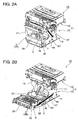
- FIG. 2A and FIG. 2B are oblique views of the printing mechanism unit that is covered by the outside case 2a and cover 3a of the printer 1, FIG. 2A showing the printing mechanism unit when the cover unit 3 is closed and FIG. 2B showing the printing mechanism unit when the cover unit 3 is open.
- the printer mechanism unit 10 has a printer frame 11 made of sheet metal to which other parts are disposed. Disposed to the printer frame 11 are a chassis-side frame unit 12 and a head-side frame unit 13 disposed horizontally to the top of the chassis-side frame unit 12.
- the chassis-side frame unit 12 has a bottom 14, left and right side panels 15 and 16, and a back panel 17.
- the roll paper compartment 7 is rendered inside the chassis-side frame unit 12.
- a support shaft 18 travels horizontally widthwise to the printer at the front bottom ends of the left and right side panels 15 and 16, and the cover unit 3 is supported pivotably on this support shaft 18 as the axis of rotation.
- the cover unit 3 has a rectangular cover frame 3b made of sheet metal, and this cover frame 3b is attached to a 4-part parallel linkage mechanism.
- This parallel linkage mechanism includes a pair of left and right front parallel links 21 and 22 and a pair of left and right rear parallel links 23 and 23.
- a rectangular box-like platen frame 25 is disposed horizontally between the tops of the four links 21 to 24.
- the platen 26 is attached horizontally to the top of the platen frame 25.
- This 4-part linkage mechanism enables the cover unit 3 to pivot between the closed position 3A shown in FIG. 2A and the open position 3B shown in FIG. 2B while holding the platen 26 substantially level.
- a damper spring 27 (cover urging member) rendered by a tension spring is attached between the cover unit 3 that opens and closes and the stationary side panel 16 of the printer frame 11, and urges the cover unit 3 to the closed position.
- the damper spring 27 prevents the cover unit 3 from dropping forcefully forward and open.
- the urging force of the damper spring 27 increases as the open angle of the cover unit 3 increases.
- an inkjet head 28, a head carriage 29 on which the inkjet head 28 is carried, and a carriage transportation mechanism are assembled inside the head-side frame unit 13 as shown in FIG. 3A .
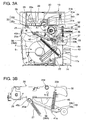
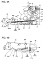
- FIG. 3A and FIG. 4A are schematic side views showing the internal configuration of the printer 1, FIG. 3A showing the cover unit 3 closed and FIG. 4A showing the cover unit 3 open.
- the roll paper 8 is stored horizontally widthwise to the printer in the roll paper compartment 7 formed inside the printer.
- the head-side frame unit 13 is attached horizontally above the roll paper compartment 7.
- the inkjet head 28, the head carriage 29, and a carriage guide shaft 30 that guides movement of the head carriage 29 widthwise to the printer are disposed to the head-side frame unit 13.
- the inkjet head 28 is mounted on the head carriage 29 with the nozzle surface 28a facing down.
- a carriage transportation mechanism having a carriage motor 31 a and a timing belt 31 b for driving the head carriage 29 bidirectionally along the carriage guide shaft 30 is mounted on the head-side frame unit 13.
- the platen 26 is disposed below the nozzle surface 28a of the inkjet head 28 with a constant gap therebetween, and defines the printing position of the inkjet head 28.
- a tension guide 32 that curves downward is disposed on the upstream side of the platen 26 in the transportation direction.
- the tension guide 32 is urged upward by a spring force, and the printing paper 8a delivered from the roll paper 8 stored in the roll paper compartment 7 is conveyed through the paper transportation path passed the printing position with a predetermined tension applied to the paper by the tension guide 32.
- first transportation roller pair 33 including a first transportation roller 33a and a first follower roller 33b
- second transportation roller pair 34 including a second transportation roller 34a and a second follower roller 34b
- third transportation roller pair 35 including a third transportation roller 35a and a third follower roller 35b.
- the first transportation roller pair 33 is disposed below the tension guide 32 at a position behind the roll paper compartment 7.
- the first transportation roller 33a is disposed horizontally widthwise to the printer between the left and right side panels 15 and 16 of the printer frame 11. Torque from a transportation motor 37 is transferred through a speed-reducing gear train 36 to the first transportation roller 33a.
- the first follower roller 33b is supported freely rotatably at the distal end part (the end part at the back of the printer) of a roller support lever 38 that is attached to the platen frame 25 on the cover unit 3 side. When the cover unit 3 is closed, the force of the damper spring 27 pushes the first follower roller 33b against the first transportation roller 33a with the printing paper 8a therebetween.
- the second transportation roller pair 34 is disposed at a position on the upstream side of the platen 26 in the transportation direction.
- the second transportation roller 34a is attached to the platen frame 25 on the cover unit 3 side, and the second follower roller 34b is disposed on the head-side frame unit 13 side.
- the cover unit 3 is closed, the second follower roller 34b is pressed with a predetermined force against the second transportation roller 34a with the printing paper 8a therebetween.
- Torque from the transportation motor 37 affixed to the chassis-side frame unit 12 is transferred through a speed-reducing gear train 40 to the second transportation roller 34a.
- the third transportation roller pair 35 is disposed at a position downstream from the platen 26 in the transportation direction.
- the third transportation roller 35a is disposed to the platen frame 25 on the cover unit 3 side, and the third follower roller 35b is disposed on the head-side frame unit 13 side.
- the third transportation roller 35a is connected to the second transportation roller 34a through a gear train not shown, and thus rotates in synchronization with the second transportation roller 34a.
- the cover unit 3 is closed, the third follower roller 35b is pressed to the third transportation roller 35a with the printing paper 8a therebetween.
- the printing paper 8a delivered from the roll paper 8 is conveyed through the first transportation roller pair 33, the tension guide 32, and the second transportation roller pair 34 over the surface of the platen 26, and through the third transportation roller pair 35 and the paper transportation path to the paper exit 4.
- the inkjet head 28 prints on the surface of the printing paper 8a as the paper travels over the printing position at the platen 26.
- the first to third transportation roller pairs 33 to 35 are driven rotationally to advance the printing paper 8a a predetermined pitch.
- the next line is then printed.
- the printing paper 8a is thus printed by the inkjet head 28 as the printing paper 8a is conveyed intermittently a predetermined pitch.
- a paper cutting mechanism such as a scissor-type cutting mechanism (not shown in the figure) is disposed to the paper exit 4 from which the printing paper 8a is discharged after printing.
- the paper cutting mechanism cuts across the width of the printing paper 8a positioned between the blades.
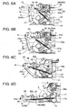
- FIG. 3B and FIG. 4B describe the support mechanism for the first follower roller 33b of the first transportation roller pair 33, FIG. 3B showing the arrangement when the cover unit 3 is closed and FIG. 4B showing the arrangement when the cover unit 3 is open.
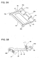
- FIG. 5A and FIG. 5B are an oblique view and a side view, respectively, of the first follower roller 33b and the roller support lever 38.
- the roller support lever 38 has left and right frame plates 41 and 42, and a rectangular frame-shaped connecting panel 43 connecting the frame plates 41 and 42.
- a roller shaft 44 spans horizontally widthwise to the printer between the distal end parts of the left and right frame plates 41 and 42, and the first follower roller 33b is supported freely rotatably on the roller shaft 44.
- a support shaft 45 spans horizontally widthwise to the printer at the base end parts of the left and right frame plates 41 and 42.
- Both axial end parts of the support shaft 45 are inserted to left and right holes 25a formed in the bottom end parts of the left and right side wall parts of the platen frame 25.
- these holes 25a are elliptical holes formed with the long axis pointing towards the first transportation roller 33a, and the axial end parts 44a and 45b of the support shaft 45 are inserted so that they can slide and rotate freely inside the holes 25a.
- the roller support lever 38 is thus attached to the platen frame 25 on the cover unit 3 side so that the roller support lever 38 can rotate freely on the support shaft 45 (axis of rotation) and can slide a predetermined stroke along the long axis of the holes 25a to and away from the first transportation roller 33a.
- damper spring 27 One end of the damper spring 27 is attached to one axial end part 45b of the support shaft 45.
- the other end of the damper spring 27 is connected to a spring catch 17a formed at a position near the bottom of the back panel 17 of the printer frame 11 at the back side of the roll paper compartment 7. This causes the tension of the damper spring 27 to act through the support shaft 45 on the first follower roller 33b at the distal end of the roller support lever 38. While the support shaft 45 moves inside the holes 25a, the first follower roller 33b is pressed by the urging force of the damper spring 27 toward the first transportation roller 33a.
- a spring catch 41 a is also formed at a position on the distal end side of the frame plate 41 of the roller support lever 38, and a spring catch 25b is formed on the platen frame 25 at a position on the back side of the printer.
- a lever lift spring 46 (lever urging member) is connected in tension between these spring catches 41a and 25b.
- a lever guide slot 47 is formed on the inside of the side panel 15 of the chassis-side frame unit 12 facing the roll paper compartment 7.
- This lever guide slot 47 is a substantially triangular slot that narrows toward the back of the printer, and the lever guide slot 47 opens toward the center of the first transportation roller 33a.
- FIG. 6A The opening and closing operation of the cover unit 3 is described next with reference to FIG. 6A, FIG. 6B, FIG. 6C, and FIG. 6D .
- the movement of the roller support lever 38 as the cover unit 3 opens and closes is described with reference to these figures.
- the roller support lever 38 When the cover unit 3 is in the closed position 3A as shown in FIG. 6A , the roller support lever 38 is urged toward the back of the printer by the tension of the damper spring 27 and the first follower roller 33b disposed to the end of the roller support lever 38 is pressed from the front to the first transportation roller 33a on the printer frame 11 side.
- the locking member 9 engages the cover unit 3
- the urging force of the damper spring 27 on the cover unit 3 is not needed, and the urging force of the damper spring 27 therefore does not work on the cover unit 3.
- the force used to lock the cover unit 3 can therefore be easily set.
- the first follower roller 33b supported on the distal end of the support shaft 45 of the roller support lever 38 is urged by the damper spring 27 to slide a predetermined stroke to and away from the first transportation roller 33a along the long axis of the holes 25a in the platen frame 25 (the direction from the center of the first follower roller 33b to the center of the first transportation roller 33a).
- the support shaft 45 does not move in the direction in which the cover unit 3 pivots, and the urging force of the damper spring 27 on the cover unit 3 is released. Because the first follower roller 33b can move while urged by the damper spring 27, the first follower roller 33b can be pressed with a predetermined urging force against the first transportation roller 33a with the printing paper 8a therebetween, thereby achieving a stable transportation force.
- the damper spring 27 thus functions primarily as an urging member that produces pressure pushing the first follower roller 33b to the first transportation roller 33a when the cover unit 3 is closed, and functions primarily as a damping member when the cover unit 3 opens to prevent the cover unit 3 from opening quickly and forcefully. Because a single damper spring 27 serves two functions, the construction is simplified and both size and cost can be reduced compared with a configuration using a plurality of parts to achieve the same function.
- the cover unit 3 is shown in the fully open position 3B in FIG. 6D and FIG. 4B .
- the platen frame 25 is stacked with the cover unit 3, and the roller support lever 38 is positioned between the platen frame 25 and the cover unit 3 (retracted position 38B).
- the roller support lever 38 therefore cannot interfere with replacing the roll paper 8.
- the roller support lever 38 is disposed so that it can rotate and move on the platen frame 25 that opens and closes with the cover unit 3, and the first follower roller 33b is disposed to the distal end of the roller support lever 38, in a printer 1 according to this embodiment of the invention.
- a damper spring 27 that buffers impact of the cover unit 3 when the cover unit 3 opens is also disposed to the roller support lever 38.
- the damper spring 27 exerts pressure pushing the first follower roller 33b against the first transportation roller 33a with the printing paper 8a therebetween when the cover unit 3 is closed.
- An urging member that applies pressure to the first transportation roller pair 33 and a separate damping member that buffers the impact of the cover unit 3 when opening are therefore not needed.
- the number of parts can therefore be reduced, the construction accordingly simplified, and the size and cost can be reduced.
- the first follower roller 33b is attached to the roller support lever 38.
- the layout and freedom of design, including the position of the first transportation roller pair, is improved because the roller support lever 38 can be adapted to the location of the first transportation roller pair 33 by using a roller support lever 38 of a length and position corresponding to the location of the first transportation roller 33a.
- the roller support lever 38 moves from the protruding position 38A to the retracted position 38B stacked with the platen frame 25 and folded to the cover unit 3. As a result, the roller support lever 38 does not interfere with replacing the roll paper, for example, when the cover unit 3 is open.
- the roller support lever 38 When the cover unit 3 is closed, the roller support lever 38 is guided by the lever guide slot 47 and the first follower roller 33b attached to the distal end of the roller support lever 38 can be reliably positioned to the stationary-side first transportation roller 33a.
- the first follower roller 33b can therefore be pressed with predetermined force against the first transportation roller 33a with the printing paper 8a therebetween.
- a rectangular frame-like connecting panel 43 that separates the roll paper compartment 7 and platen frame 25 is disposed to the roller support lever 38.
- inertia may cause the roll paper 8 to roll more than necessary.
- the printing paper 8a on the outside of the roll paper 8 may loosen and bulge to the outside, and may even rise into the paper transportation path and cause a paper jam.
- this connecting panel 43 to the roller support lever 38, printing paper 8a slack from the roll paper 8 can be suppressed and prevented from rising into the paper transportation path.
- Closing the cover in the related art can be difficult because the cover must be closed in resistance to the spring force urging the transportation roller pair together.
- the cover unit 3 can be easily closed with at least one embodiment of the invention, however, because the damper spring 27 also changes an urging force in the direction closing the cover unit 3.
- the urging force of the damper spring 27 changes from a force closing the cover unit 3 to pressure on the first transportation roller pair 33.
- the urging force of the damper spring 27 does not work on the cover unit 3 side or is a weak force. The force required to lock the cover unit 3 can therefore be easily set.
- the lever lift spring 46 can buffer the impact when a shock load is applied (such as when the user closes the cover violently), and damage to the holes 25a, rollers 33a and 33b, and other parts can be prevented.
Landscapes
- Accessory Devices And Overall Control Thereof (AREA)
- Casings For Electric Apparatus (AREA)
- Handling Of Continuous Sheets Of Paper (AREA)
Claims (10)
- Drucker, der Folgendes umfasst:eine Abdeckung (3a), die so an einem Druckergestell befestigt ist, dass sie geöffnet und geschlossen werden kann;Transporteinrichtung, die eine Transportwalze (33a, 33b) beinhaltet, die zum Transportieren von Druckerpapier ausgebildet ist; undein Abdeckungsdrängelement (27), das zwischen der Abdeckung (3a) und dem Druckergestell befestigt ist;wobei das Abdeckungsdrängelement (27) so ausgebildet ist, dass es die Abdeckung (3a) in die geschlossene Richtung drängt, wenn die Abdeckung (3a) geöffnet ist;dadurch gekennzeichnet, dassdie Transporteinrichtung ein Transportwalzenpaar (33a, 33b) umfasst, unddas Abdeckungsdrängelement (27) ferner so ausgebildet ist, dass es das Walzenpaar (33a, 33b) bei geschlossener Abdeckung (3a) in eine Richtung drängt, in der es zusammengedrückt wird.
- Drucker nach Anspruch 1, wobei:das Transportwalzenpaar (33a, 33b) eine gestellseitige Walze (33a), die am Druckergestell befestigt ist, und eine abdeckungsseitige Walze (33b), die an der Abdeckung (3 a) befestigt ist, beinhaltet;die abdeckungsseitige Walze (33b) so angeordnet ist, dass sie sich von der gestellseitigen Walze (33a) trennt, wenn die Abdeckung (3a) geöffnet wird; unddas Abdeckungsdrängelement (27) so angeordnet ist, dass es die abdeckungsseitige Walze (33b) bei geschlossener Abdeckung (3a) an die gestellseitige Walze (33a) drückt.
- Drucker nach Anspruch 2, der ferner Folgendes umfasst:einen Walzenstützhebel (38), der die abdeckungsseitige Walze (33b) stützt;wobei der Walzenstützhebel (38) an der Abdeckung (3a) befestigt ist, so dass sich der Walzenstützhebel (38) bezüglich der gestellseitigen Walze (33a) bewegen kann.
- Drucker nach Anspruch 2, der ferner Folgendes umfasst:einen Walzenstützhebel (38), der die abdeckungsseitige Walze (33b) stützt;wobei der Walzenstützhebel (38) an der Abdeckung (3 a) befestigt ist, so dass sich der Walzenstützhebel (38) auf einer Drehachse drehen kann; undder Walzenstützhebel (38) so angeordnet ist, dass er sich bei geöffneter Abdeckung (3 a) in eine zurückgezogene Position, anliegend an die Abdeckung (3 a), dreht; und sich bei geschlossener Abdeckung (3a) in eine hervorstehende Position dreht, die in die Richtung hervorsteht, in der die abdeckungsseitige Walze (33b) gegen die gestellseitige Walze (33a) gedrückt wird.
- Drucker nach einem der vorhergehenden Ansprüche, der ferner Folgendes umfasst:ein Papierrollenfach (7) zur Unterbringung von Druckpapier, das auf eine Rolle gewickelt ist;wobei die Abdeckung (3a) so angeordnet ist, dass sie an ihrer Unterseite auf einer Trägerachse (18) zwischen einer aufrechten geschlossenen Position und einer im Wesentlichen waagrechten offenen Position schwenkbar ist, und das Papierrollenfach (7) öffnet und schließt.
- Drucker nach Anspruch 5, wobei:die gestellseitige Walze (33a) in einer Position angeordnet ist, die der Position der Abdeckung (3a) bei geschlossener Abdeckung (3a) gegenüberliegt, wobei das Papierrollenfach (7) im Druckergestell dazwischen liegt; unddas Druckpapier, das von der im Papierrollenfach (7) untergebrachten Papierrolle ausgegeben wird, so angeordnet ist, dass es zwischen der gestellseitigen Walze (33a) und der abdeckungsseitigen Walze (33b) zu einem Austritt geführt wird, der sich auf der Seite der Abdeckung (3a) befindet.
- Drucker nach Anspruch 5, wobei der Walzenstützhebel (38) beweglich an einer an der Abdeckung (3a) angeordneten Hebelstützeinheit angeordnet ist; und die abdeckungsseitige Walze (33b) vom Walzenstützhebel (38) getragen wird.
- Drucker nach Anspruch 7, wobei:die Hebelstützeinheit ein ellipsenförmiges Loch (25a) ist;eine Trägerachse (45) am Walzenstützhebel (38) befestigt und in das Loch (25a) eingesetzt ist, so dass sich die Trägerachse (45) drehen und bewegen kann; unddas Abdeckungsdrängelement (27) zwischen dem Druckergestell und der Trägerachse (45) befestigt ist.
- Drucker nach Anspruch 5, der ferner Folgendes umfasst
ein Hebeldrängelement (46), das an der Abdeckung (3a) angeordnet ist, um den Walzenstützhebel (38) an die Abdeckungsseite zu drängen; und
eine Hebelführungseinheit (47a), die im Druckergestell ausgebildet ist;
wobei der Walzenstützhebel (38) bei geöffneter Abdeckung (3a) so ausgebildet ist, dass er sich durch die Drängkraft des Hebeldrängelements (46) in eine zurückgezogene Position, anliegend an die Abdeckung, bewegt, und
der Walzenstützhebel (38) bei geschlossener Abdeckung (3a) so ausgebildet ist, dass er sich, geführt von der Hebelführungseinheit (47a), in eine hervorstehende Position bewegt. - Drucker nach Anspruch 7, wobei der Walzenstützhebel (38) einen Plattenteil umfasst, der zwischen dem Papierrollenfach (7) und der Abdeckung (3a) interveniert, wenn die Abdeckung (3a) geschlossen ist.
Applications Claiming Priority (1)
| Application Number | Priority Date | Filing Date | Title |
|---|---|---|---|
| JP2007300203A JP5109616B2 (ja) | 2007-11-20 | 2007-11-20 | プリンタ |
Publications (2)
| Publication Number | Publication Date |
|---|---|
| EP2062736A1 EP2062736A1 (de) | 2009-05-27 |
| EP2062736B1 true EP2062736B1 (de) | 2015-10-28 |
Family
ID=40120277
Family Applications (1)
| Application Number | Title | Priority Date | Filing Date |
|---|---|---|---|
| EP08019917.7A Ceased EP2062736B1 (de) | 2007-11-20 | 2008-11-14 | Drucker |
Country Status (4)
| Country | Link |
|---|---|
| US (1) | US8157461B2 (de) |
| EP (1) | EP2062736B1 (de) |
| JP (1) | JP5109616B2 (de) |
| CN (2) | CN102139586B (de) |
Families Citing this family (3)
| Publication number | Priority date | Publication date | Assignee | Title |
|---|---|---|---|---|
| JP5316087B2 (ja) * | 2009-03-02 | 2013-10-16 | セイコーエプソン株式会社 | オートカッターおよびオートカッター付きプリンター |
| JP5589376B2 (ja) * | 2009-12-21 | 2014-09-17 | セイコーエプソン株式会社 | カバーユニットおよびプリンター |
| JP6669425B2 (ja) * | 2013-12-26 | 2020-03-18 | サトーホールディングス株式会社 | プリンタ |
Family Cites Families (20)
| Publication number | Priority date | Publication date | Assignee | Title |
|---|---|---|---|---|
| JPS6032594B2 (ja) * | 1979-08-04 | 1985-07-29 | 日立工機株式会社 | ラインプリンタのアッパカバ−装置 |
| JPS58189659U (ja) * | 1982-06-10 | 1983-12-16 | 三洋電機株式会社 | フアクシミリ装置 |
| JPH0640055A (ja) | 1992-07-27 | 1994-02-15 | Sumitomo Electric Ind Ltd | サーマルプリンタ |
| WO1998043820A1 (fr) * | 1997-04-02 | 1998-10-08 | Seiko Epson Corporation | Mecanisme de chargement de rouleau de papier pour imprimantes |
| DE69922757T2 (de) * | 1998-10-02 | 2005-12-15 | Seiko Epson Corp. | Drucker und Verfahren zu dessen Steuerung |
| JP3855604B2 (ja) * | 2000-06-06 | 2006-12-13 | セイコーエプソン株式会社 | ロール紙装填機構およびロール紙プリンタ |
| JP4016585B2 (ja) * | 1999-09-22 | 2007-12-05 | セイコーエプソン株式会社 | プリンタ |
| KR100566221B1 (ko) * | 1999-09-22 | 2006-03-29 | 세이코 엡슨 가부시키가이샤 | 롤지 수용부를 구비한 프린터 |
| EP1108556B1 (de) * | 1999-12-15 | 2003-04-16 | Seiko Epson Corporation | Drucker |
| US6617682B1 (en) * | 2000-09-28 | 2003-09-09 | Intel Corporation | Structure for reducing die corner and edge stresses in microelectronic packages |
| KR100385586B1 (ko) * | 2000-12-21 | 2003-05-27 | 삼성전기주식회사 | 프린터용 클램쉘 장치 |
| DE60211596T2 (de) * | 2001-06-25 | 2006-12-21 | Seiko Epson Corp. | Drucker |
| JP2003165677A (ja) * | 2001-11-30 | 2003-06-10 | Ricoh Co Ltd | 両面装置及びそれを備えた画像形成装置 |
| KR100452677B1 (ko) * | 2002-01-18 | 2004-10-14 | 세이코 엡슨 가부시키가이샤 | 프린터 |
| JP4206854B2 (ja) | 2003-07-22 | 2009-01-14 | ブラザー工業株式会社 | 画像形成装置 |
| JP4535839B2 (ja) | 2004-10-26 | 2010-09-01 | 京セラミタ株式会社 | 画像形成装置 |
| JP4815931B2 (ja) * | 2005-08-01 | 2011-11-16 | セイコーエプソン株式会社 | 紙切断装置およびプリンタ |
| US8462184B2 (en) * | 2005-12-08 | 2013-06-11 | Ncr Corporation | Two-sided thermal printer control |
| US7914218B2 (en) * | 2006-06-29 | 2011-03-29 | Toshiba Tec Kabushiki Kaisha | Thermal printer and printing device |
| JP5298954B2 (ja) * | 2008-04-10 | 2013-09-25 | セイコーエプソン株式会社 | プリンターの記録紙搬送制御方法およびプリンター |
-
2007
- 2007-11-20 JP JP2007300203A patent/JP5109616B2/ja not_active Expired - Fee Related
-
2008
- 2008-11-14 EP EP08019917.7A patent/EP2062736B1/de not_active Ceased
- 2008-11-19 CN CN201110035039.3A patent/CN102139586B/zh not_active Expired - Fee Related
- 2008-11-19 CN CN2008101781173A patent/CN101445006B/zh not_active Expired - Fee Related
- 2008-11-20 US US12/313,386 patent/US8157461B2/en not_active Expired - Fee Related
Also Published As
| Publication number | Publication date |
|---|---|
| CN102139586B (zh) | 2014-06-04 |
| EP2062736A1 (de) | 2009-05-27 |
| JP5109616B2 (ja) | 2012-12-26 |
| US20090129846A1 (en) | 2009-05-21 |
| CN102139586A (zh) | 2011-08-03 |
| JP2009125973A (ja) | 2009-06-11 |
| US8157461B2 (en) | 2012-04-17 |
| CN101445006B (zh) | 2011-03-30 |
| CN101445006A (zh) | 2009-06-03 |
Similar Documents
| Publication | Publication Date | Title |
|---|---|---|
| KR101505205B1 (ko) | 커터가 달린 프린터 | |
| EP1270242B1 (de) | Drucker | |
| JP5106238B2 (ja) | カッター付きプリンタ | |
| US8197060B2 (en) | Printer opening and closing mechanism which prevents interference of the platen and the inkjet head | |
| EP2042327A2 (de) | Wärmedrucker | |
| US8469617B2 (en) | Printer platen support mechanism and roll paper printer | |
| US8287198B2 (en) | Printer | |
| EP2062736B1 (de) | Drucker | |
| US8727649B2 (en) | Roll paper loading mechanism and printing device | |
| WO1999051443A1 (fr) | Imprimante | |
| JP6146173B2 (ja) | プリンター | |
| JP2007175911A (ja) | ロール紙プリンタ | |
| EP2368717B1 (de) | Drucker | |
| JP3700461B2 (ja) | プリンタ | |
| JP4876576B2 (ja) | プリンタ | |
| US8550734B2 (en) | Transportation guide mechanism and recording device having the same | |
| JP4661591B2 (ja) | プリンタ | |
| JP7551541B2 (ja) | プリンタ | |
| JP3565043B2 (ja) | プリンタのロール紙装填機構 | |
| JP2010167785A (ja) | プリンタおよび紙押さえ機構 | |
| JP2003312076A (ja) | プリンタ | |
| EP2522518B1 (de) | Punkt-Matrix-Drucker für Sparbücher oder Quittungen | |
| JP2010201684A (ja) | ロール紙収納部の開閉蓋ユニットおよびロール紙プリンター |
Legal Events
| Date | Code | Title | Description |
|---|---|---|---|
| PUAI | Public reference made under article 153(3) epc to a published international application that has entered the european phase |
Free format text: ORIGINAL CODE: 0009012 |
|
| AK | Designated contracting states |
Kind code of ref document: A1 Designated state(s): AT BE BG CH CY CZ DE DK EE ES FI FR GB GR HR HU IE IS IT LI LT LU LV MC MT NL NO PL PT RO SE SI SK TR |
|
| AX | Request for extension of the european patent |
Extension state: AL BA MK RS |
|
| 17P | Request for examination filed |
Effective date: 20090717 |
|
| 17Q | First examination report despatched |
Effective date: 20090918 |
|
| AKX | Designation fees paid |
Designated state(s): DE FR GB IT |
|
| GRAP | Despatch of communication of intention to grant a patent |
Free format text: ORIGINAL CODE: EPIDOSNIGR1 |
|
| RIC1 | Information provided on ipc code assigned before grant |
Ipc: B41J 29/02 20060101ALI20150415BHEP Ipc: B41J 13/03 20060101ALI20150415BHEP Ipc: B41J 15/04 20060101AFI20150415BHEP |
|
| INTG | Intention to grant announced |
Effective date: 20150506 |
|
| GRAS | Grant fee paid |
Free format text: ORIGINAL CODE: EPIDOSNIGR3 |
|
| GRAA | (expected) grant |
Free format text: ORIGINAL CODE: 0009210 |
|
| AK | Designated contracting states |
Kind code of ref document: B1 Designated state(s): DE FR GB IT |
|
| REG | Reference to a national code |
Ref country code: GB Ref legal event code: FG4D |
|
| REG | Reference to a national code |
Ref country code: FR Ref legal event code: PLFP Year of fee payment: 8 |
|
| REG | Reference to a national code |
Ref country code: DE Ref legal event code: R096 Ref document number: 602008040857 Country of ref document: DE |
|
| REG | Reference to a national code |
Ref country code: DE Ref legal event code: R097 Ref document number: 602008040857 Country of ref document: DE |
|
| PLBE | No opposition filed within time limit |
Free format text: ORIGINAL CODE: 0009261 |
|
| STAA | Information on the status of an ep patent application or granted ep patent |
Free format text: STATUS: NO OPPOSITION FILED WITHIN TIME LIMIT |
|
| 26N | No opposition filed |
Effective date: 20160729 |
|
| REG | Reference to a national code |
Ref country code: FR Ref legal event code: PLFP Year of fee payment: 9 |
|
| REG | Reference to a national code |
Ref country code: FR Ref legal event code: PLFP Year of fee payment: 10 |
|
| REG | Reference to a national code |
Ref country code: FR Ref legal event code: PLFP Year of fee payment: 11 |
|
| PGFP | Annual fee paid to national office [announced via postgrant information from national office to epo] |
Ref country code: GB Payment date: 20210930 Year of fee payment: 14 |
|
| PGFP | Annual fee paid to national office [announced via postgrant information from national office to epo] |
Ref country code: DE Payment date: 20210929 Year of fee payment: 14 |
|
| PGFP | Annual fee paid to national office [announced via postgrant information from national office to epo] |
Ref country code: IT Payment date: 20211012 Year of fee payment: 14 Ref country code: FR Payment date: 20211018 Year of fee payment: 14 |
|
| REG | Reference to a national code |
Ref country code: DE Ref legal event code: R119 Ref document number: 602008040857 Country of ref document: DE |
|
| GBPC | Gb: european patent ceased through non-payment of renewal fee |
Effective date: 20221114 |
|
| PG25 | Lapsed in a contracting state [announced via postgrant information from national office to epo] |
Ref country code: IT Free format text: LAPSE BECAUSE OF NON-PAYMENT OF DUE FEES Effective date: 20221114 Ref country code: GB Free format text: LAPSE BECAUSE OF NON-PAYMENT OF DUE FEES Effective date: 20221114 Ref country code: DE Free format text: LAPSE BECAUSE OF NON-PAYMENT OF DUE FEES Effective date: 20230601 |
|
| PG25 | Lapsed in a contracting state [announced via postgrant information from national office to epo] |
Ref country code: FR Free format text: LAPSE BECAUSE OF NON-PAYMENT OF DUE FEES Effective date: 20221130 |