EP2060868A2 - Dispositif de sécurisation pour une amorce - Google Patents
Dispositif de sécurisation pour une amorce Download PDFInfo
- Publication number
- EP2060868A2 EP2060868A2 EP08019240A EP08019240A EP2060868A2 EP 2060868 A2 EP2060868 A2 EP 2060868A2 EP 08019240 A EP08019240 A EP 08019240A EP 08019240 A EP08019240 A EP 08019240A EP 2060868 A2 EP2060868 A2 EP 2060868A2
- Authority
- EP
- European Patent Office
- Prior art keywords
- barrier
- securing
- securing device
- ignition
- unlocking
- Prior art date
- Legal status (The legal status is an assumption and is not a legal conclusion. Google has not performed a legal analysis and makes no representation as to the accuracy of the status listed.)
- Ceased
Links
Images


Classifications
-
- F—MECHANICAL ENGINEERING; LIGHTING; HEATING; WEAPONS; BLASTING
- F42—AMMUNITION; BLASTING
- F42C—AMMUNITION FUZES; ARMING OR SAFETY MEANS THEREFOR
- F42C15/00—Arming-means in fuzes; Safety means for preventing premature detonation of fuzes or charges
- F42C15/34—Arming-means in fuzes; Safety means for preventing premature detonation of fuzes or charges wherein the safety or arming action is effected by a blocking-member in the pyrotechnic or explosive train between primer and main charge
-
- F—MECHANICAL ENGINEERING; LIGHTING; HEATING; WEAPONS; BLASTING
- F42—AMMUNITION; BLASTING
- F42C—AMMUNITION FUZES; ARMING OR SAFETY MEANS THEREFOR
- F42C15/00—Arming-means in fuzes; Safety means for preventing premature detonation of fuzes or charges
- F42C15/005—Combination-type safety mechanisms, i.e. two or more safeties are moved in a predetermined sequence to each other
-
- F—MECHANICAL ENGINEERING; LIGHTING; HEATING; WEAPONS; BLASTING
- F42—AMMUNITION; BLASTING
- F42C—AMMUNITION FUZES; ARMING OR SAFETY MEANS THEREFOR
- F42C15/00—Arming-means in fuzes; Safety means for preventing premature detonation of fuzes or charges
- F42C15/18—Arming-means in fuzes; Safety means for preventing premature detonation of fuzes or charges wherein a carrier for an element of the pyrotechnic or explosive train is moved
- F42C15/188—Arming-means in fuzes; Safety means for preventing premature detonation of fuzes or charges wherein a carrier for an element of the pyrotechnic or explosive train is moved using a rotatable carrier
Definitions
- the invention relates to a safety device for an igniter, comprising a detonating chain with an ignition means and a barrier, which is locked in its Sicher ein by a first securing means and a first independent second securing means provided for an unlocking action due to two independent physical Entommesparameter are.
- a safety device for an igniter is used to prevent inadvertent activation of a main charge of an explosion device, but an activation of the main charge after a release should be possible.
- the safety device is part of a detonator for igniting the main charge, which is provided with a detonating chain of two or more ignition means.
- the first ignition means is activated, e.g. a puncture-sensitive mini-detonator that is pierced by a mechanical means for firing. Explosive energy of the first ignition means is transmitted by a corresponding arrangement of the first two ignition means to the second ignition means, which may be designed as a booster. This can transfer its explosive energy to an initial charge or main charge.
- a safety device of the type mentioned in which the ignition chain comprises a second ignition means and the barrier blocks a gap between the two ignition means in a security and can be brought into a focus position by a release movement releasing the gap.
- the provision of the two independent securing means ensures a high degree of security.
- the blocking of the gap can be achieved with a compact component.
- the arming parameters are desirably physically independent of each other such that the unlocking action is dependent on physically independent parameters, e.g. Forces, can be triggered. These can be an acceleration, a spin, a dynamic pressure, a time after a launch or an impact pressure.
- the blocking can be achieved by placing the barrier in the gap and at least partially filling it. The barrier releases the space between the ignition means with its release movement. In this case, the barrier can be removed from the gap or changed so that the gap is vacant, e.g. by pivoting the barrier in the intermediate space from a horizontal to a vertical position.
- the shared gap does not have to be the entire gap between the firing means.
- the ignition means may be explosive charges, wherein the ignition chain in addition to the two ignition means may comprise a further ignition means, which is arranged in the ignition chain before, in particular behind the two ignition means.
- the barrier serves to exclude and / or redirect ignition energy of the first ignition means such that ignition of the second ignition means is reliably prevented by ignition energy of the first ignition means.
- the securing means are used in particular for mechanically locking the barrier in such a way that movement of the barrier from its securing into the armed position is reliably prevented. By unlocking the barrier can be released from the corresponding securing means in such a way that it is movable in the focus, either for example, by inertia independently, or powered by a means of movement.
- the ignition means remain at a release movement to each other dormant. There is no need to leave room for moving an ignition means, whereby the safety device can be made compact.
- the two ignition means remain in the release movement expediently not only to each other but also to a housing dormant.
- the first securing means for implementing the arming parameter is provided directly mechanically in the unlocking action. It can be unlocked independently of an electronic control and thus cheap and robust.
- the first securing means serves to directly absorb energy of a release parameter, in particular by its own inertia, and to convert it mechanically into the unlocking action.
- a high variability in triggering the unlocking action can be achieved by an electronic control unit for triggering the unlocking action of the second securing means.
- the triggering is not dependent on the presence of forces, but can be freely controlled, whereby a high Vorrohr security can be achieved.
- activation of the detonating chain may be restricted to a specified period of time after a launch so that a projectile can not fire immediately after leaving a launching tube. Or it can be integrated over time a back pressure or a flow and be closed on a route, so that an ignition is only allowed a distance from the launch tube.
- the unlock action may be a movement of a micromotor that drives the release movement of the barrier.
- the second securing means is provided to release the barrier by the unlocking action mechanically to carry out the release movement.
- An engine can be dispensed with and the safety device can be kept simple and compact.
- the securing device comprises an electronic control which is prepared for controlling the unlocking action of at least one of the securing means.
- the controller may in turn be connected to a sensor for sensing one of the arming parameters.
- the control unit may initiate the unlocking action.
- the electronic control is connected to two sensors for sensing two different Entommesparametern and provided for controlling the Entriegel pain the second securing means based on both Entommesparameter.
- the security device can be used universally and e.g. depending on the application, can be programmed to process one or both arming parameters. If the security device is used, for example, in a swirled projectile, then the controller can be programmed to process the data of that sensor which senses the swirl. If the safety device is used on a non-spinning projectile, the controller can be programmed to process data from another sensor, such as a back pressure sensor. It is also possible to process the data from both sensors to control the unlocking action more complexly.
- the two unlocking parameters are expediently different from the unlocking parameter of the first securing means.
- the second securing means comprises a loading means for actuating the unlocking action by means of a discharge.
- the second securing means can thereby be kept compact.
- the charging means may be any means capable of storing a mechanical, chemical or electrical charge.
- the load is a spring through which an unlocking action is driven.
- the securing means may be particularly compact if the charge is a chemical charge, e.g. in the form of a pyrotechnic charge.
- the charging means may be configured to accumulate a charge, e.g. in the form of a pressure, which may be formed by a dynamic pressure, comprising a retaining element, e.g. pushes a bolt away and unlocks the barrier.
- the unlocking action can be particularly simple and the securing means particularly compact, when the discharge is intended, a holding element, which is intended to hold the barrier, from another element of the securing means to separate and throw off.
- a bolt can be dropped, in particular blasted, whereby a previously solid connection can be solved in a simple manner.
- the first securing means has a double-bolt system. This simple system is particularly safe with the two bolts, which can only be activated in one chain, when detecting a longer lasting acceleration than arming parameters.
- the safety device can be kept very simple. If the securing device comprises unlocking means for moving the barrier into the armed position, the securing device can also be used in projectiles without swirling.
- a particularly simple Entriegelstoff is a spring.
- the unlocking means e.g. the spring is not fundamentally in a condition permitting movement of the barrier, but will only be able to move the barrier when a release criterion is met.
- a Entommeskriterium is an unlocking action of one of the securing means. If the first securing means is provided to load the unlocking means by an unlocking action, then just that security can be achieved.
- the loading may be cocking, e.g. a spring.
- a compact and robust loading of Entriegelffens can be achieved if the first securing means has an inclined to an unlocking surface, which causes the movement in the unlocking the charge by a movement of a loading means along the surface.
- the surface is guided along a spring arm, which is so tense.
- the compactness of the safety device can be further increased if the first ignition means is particularly small and yet sufficient in its force to ignite the second ignition means.
- the first ignition means comprises a projectile for igniting the second ignition means.
- the ignition energy of the first ignition means is transmitted by kinetic energy of the projectile to the second ignition means, which by the pressure wave of the impinging projectile Ignition can be brought.
- the projectile may be a bolt or a lid of the first ignition means, which is blasted off by a detonation of the first ignition means in the direction of the second ignition means.
- the object of the barrier is to reliably interrupt the ignition chain even in the case of a misfire of the first ignition means, so that the ignition energy of the first ignition means does not possibly reach the second ignition means.
- the first ignition means does not have to be completely shielded by the second ignition means, since no free jet of fire propagates the ignition energy, and the barrier can be compact.
- particularly high stability requirements are placed on the barrier. These requirements can be met if the barrier comprises two different metals, whereby two different properties of metals can be used together, for example a high breaking strength combined with a high degree of hardness.
- the shielding function of the barrier is particularly safe if it has a zone of harder metal between the ignition means and another zone of softer metal outside this zone.
- a harder metal is a WC hard metal, with a tungsten carbide content of over 90%.
- the flexural strength with possibly less than 2000 N / mm 2 is not very high, also they are quite expensive and expensive to process for a shaping of the entire barrier, so that the embedding of the harder metal proposed in the softer metal becomes. This can be characterized by a lower hardness than the harder metal, in particular by a simpler machinability for easier processing.
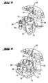
- Fig. 1 shows a fuse device 2 for an igniter with a housing 4, in the upper part of an electronic control unit 6 and including a firing chain 8 is arranged, which comprises a first and a second ignition means 10 and 14, respectively.
- the ignition chain 8 includes a detonator as a first ignition means 10 in a center axis of the igniter, wherein the center axis with respect to a rotation about a direction of flight 12 can be seen.
- an ignition amplifier is arranged as a second ignition means 14, which is aligned on an underside of the overlying detonator for receiving ignition energy from there.
- a barrier 16 which at their in Fig.
- FIG. 1 shown position a passage between the ignition means 10, 14 blocked.
- a pin 18 of a double pin system 20 is shown cut, which is pressed by a spring 22 in the direction of flight 12.
- the double pin system 20 is part of a first securing means 24 for locking the barrier 16 in its securing position.
- a second securing means 26 is shown, which is designed as a force element.
- Fig. 2 is the barrier 16 shown from below, with "up” in the direction of flight 12 and “down” opposite to the direction of flight 12 can be seen.
- Fig. 3 shows the ignition chain 8 in its safety.
- a zone 36 of the barrier blocks a gap between the two ignition means 10, 14 by filling the gap. The blockage is achieved by blocking a passage between the end of the first firing means 10 facing the second firing means 14 and the end of the second firing means 14 facing the first firing means 10 so that any direct line between them Ends through the barrier 16 runs.
- the barrier 16 is at a pivot point 38 by a in Fig. 2 held bolts 39 and prevented by a holding member 40 of the force element 26 from being able to pivot radially outwardly in a release movement. As in Fig. 2 can be seen, the barrier 16 is also applied to the second bolt 18, by which it is prevented from, in Fig. 2 to pivot clockwise in the release movement.
- the ignition chain 8 is interrupted by the barrier 16.
- the locking of the barrier 16 takes place on the one hand directly by the force element 26 and the other by the second pin 18 and thus corresponds to the requirement STANAG 4187th
- the second pin 18 is in turn locked by the first pin 30, as a ball 42 between the pin 18th , 30 prevents a translational movement of the second pin 18.
- the ball 42 is disposed in a groove 44 of the second pin 18 and would have to be pushed out upon movement of the second pin 18 down from the groove 44. This is prevented by the first pin 30, which blocks the outward movement of the ball 42 from the groove 44.
- the Entommesvorgang begins immediately after a launch of the projectile, part of which is the safety device 2. Due to the high acceleration of the safety device 2 when shooting in the direction of flight 12, the two bolts 18, 30 by their inertia relative to eg Barrier 16 to the rear and against the spring forces of the springs 22, 28 pressed. However, a movement of the second bolt 18 is initially blocked by the ball 42. However, the first pin 30 is free in its downward movement and is inserted in the in Fig. 4 pressed position shown. Now, the ball 42 is pushed out of the groove 44 and into a taper 46 of the first pin 30 by the inertial force of the second pin 18, so that the ball 42 releases downward movement of the second pin 18, as in FIG Fig. 4 is shown.
- the locking spring 32 engages behind an undercut 47 in the second pin 18 and thus blocks a return movement of the second pin 18 in the locking position.
- a contact element 48 in the form of a pin is moved out of a contact unit 50, so that an electrical contact in the contact unit 50 is interrupted. This is registered by the control unit 6 and used to control at least one further unlocking action.
- an unlocking means 52 designed as a spring is loaded to move the barrier 16 into its in-focus position by tensioning the spring.
- loading means 54 slides along an inclined surface 56 of the second bolt 18 and - by the inclined surface 56 down, ie in the unlocking of the second bolt 18, is moved - stretched and thus loaded.
- the loaded unlocking means 52 now exerts a pressure on the barrier 16 in its armed position, which remains held by the still locked second securing means 26, so that the barrier 16 is not yet moved by the pressure.
- the sequence of an unlocking program is started in the control unit 6.
- a predetermined unlocking parameter e.g. to a back pressure or a centrifugal force - and thus to a spin - or a pressure generated by a surcharge.
- the centrifugal force can be measured by pressing in or against the securing device 2 an element against a spring pressure to the outside and so against a contact and the element closes this.
- Other electrically interrogated sensors 57 connected to the control unit 6 are also conceivable.
- unlocking parameter stored in the control unit 6 or selected by the control unit 6 reaches a predetermined or from the control unit 6 fixed value, it is controlled by another unlocking action. It is also conceivable, the unlocking action by a timer and without sensor to control.
- the unlocking action will be in the in Fig. 5 shown embodiment completed by the second securing means 26.
- the securing means 26 is controlled by the control unit 6 and comprises a charging means with a pyrotechnic charge, which is now electrically ignited.
- a retaining element 58 in the form of a bolt which is provided for holding the barrier 16, blasted from the remaining securing means 26.
- a vent opening 60 is present in the igniter 2 ( Fig. 1 ), can escape through the displaced by the retaining element air and possibly explosive gases of the explosive charge.
- the charging means may have a charge in the form of a tensioned spring which is released by the unlocking action.
- Other forms of stored energy are also conceivable.
- the barrier 16 can perform its release movement and take its focus, which in Fig. 6 is shown.
- the release movement can be effected here by the Entriegelstoff 52 that the barrier pushes outward, or caused by centrifugal forces generated by swirl, which are supported by Entriegelstoff 52 only. A stop stops the release movement.
- the barrier 16 In its armed position, the barrier 16 is held by the spring 34, which in Fig. 7 is shown. It snaps behind the barrier and holds it in place, preserving its focus status.
- the barrier 16 With the release movement, the barrier 16 is removed from a gap 62 between the ignition means 10, 14 so that it is released. Now, an explosive energy can be transmitted from the first ignition means 10 to the second ignition means 14. Ignition of the first ignition means 10 is controlled by the control unit 6 according to programmable parameters and values of the parameters, e.g. by time, route or surcharge.
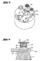
- Fig. 8 shows the two ignition means 10, 14 and the barrier 16 in the space 62 in a schematic sectional view.
- the first ignition means 10 comprises in a housing 64, one or more pyrotechnic charges 66, which by the Control unit 6 controlled ignition contacts 68 can be ignited electrically.
- a cover-shaped projectile 70 is blasted down at very high speed. If the barrier 16 is removed from the gap 62, the projectile 70 hits the second ignition means 14 and transfers ignition energy in the form of kinetic energy to the second ignition means 14, by which it is ignited.
- the barrier 16 In the case of a malfunction of the safety device, in particular a faulty detonation of the first ignition means 10, it is the task of the barrier 16 to prevent this transfer of ignition energy.
- it comprises a zone 71 of a hard metal, e.g. a carbide from the material group K10 of ISO standard 513, which is adapted in such a way to the first ignition means 10 that it has a sufficient hardness to intercept the projectile 70.
- the zone 71 adjoins another zone 72, which has a softer and more malleable metal.
- the cemented carbide is embedded in the zone 72 of softer metal.
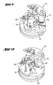
- FIGS. 9 and 10 show a further embodiment of a safety device 74 for a detonator.
- the following description is essentially limited to the differences from the exemplary embodiment in the preceding figures, to which reference is made with regard to features and functions that remain the same. Substantially identical components are basically numbered with the same reference numerals.
- Fig. 9 is the securing device 74 in its security and in Fig. 10 shown in their focus.
- the securing device 74 accommodates a barrier 76, whose release movement proceeds as described above, but in contrast to the barrier 16 carries the first ignition means 10.
- the first ignition means 10 is arranged outside the center axis, so that a faulty detonation directs the ignition energy into a holding plate 78 and does not reach the second ignition means 14.
- the barrier 76 blocks a gap between the ignition means 10, 14 by at least partially filling it. Only in the armed position is the first ignition means 10 in the center axis and thus arranged directly above the second ignition means 14 and directed thereto, so that the ignition energy can be transmitted and the ignition chain 8 is not interrupted.
Landscapes
- Engineering & Computer Science (AREA)
- General Engineering & Computer Science (AREA)
- Air Bags (AREA)
- Fuses (AREA)
- Automotive Seat Belt Assembly (AREA)
- Lock And Its Accessories (AREA)
- Aiming, Guidance, Guns With A Light Source, Armor, Camouflage, And Targets (AREA)
Applications Claiming Priority (1)
| Application Number | Priority Date | Filing Date | Title |
|---|---|---|---|
| DE102007054777A DE102007054777B3 (de) | 2007-11-16 | 2007-11-16 | Sicherungseinrichtung für einen Zünder |
Publications (2)
| Publication Number | Publication Date |
|---|---|
| EP2060868A2 true EP2060868A2 (fr) | 2009-05-20 |
| EP2060868A3 EP2060868A3 (fr) | 2013-02-20 |
Family
ID=40303675
Family Applications (1)
| Application Number | Title | Priority Date | Filing Date |
|---|---|---|---|
| EP08019240A Ceased EP2060868A3 (fr) | 2007-11-16 | 2008-11-04 | Dispositif de sécurisation pour une amorce |
Country Status (4)
| Country | Link |
|---|---|
| US (1) | US8381650B2 (fr) |
| EP (1) | EP2060868A3 (fr) |
| CA (1) | CA2639467C (fr) |
| DE (1) | DE102007054777B3 (fr) |
Cited By (5)
| Publication number | Priority date | Publication date | Assignee | Title |
|---|---|---|---|---|
| CN107121033A (zh) * | 2017-06-27 | 2017-09-01 | 湖北三江航天红林探控有限公司 | 一种电磁惯性复合转子式隔离机构 |
| CN107121034A (zh) * | 2017-06-27 | 2017-09-01 | 湖北三江航天红林探控有限公司 | 一种热熔合金惯性复合转子式隔离机构 |
| CN107144187A (zh) * | 2017-06-27 | 2017-09-08 | 湖北三江航天红林探控有限公司 | 一种火药惯性复合转子式隔离机构 |
| CN107144188A (zh) * | 2017-06-27 | 2017-09-08 | 湖北三江航天红林探控有限公司 | 一种基于惯性的电磁约束式隔离机构 |
| CN107152897A (zh) * | 2017-06-27 | 2017-09-12 | 湖北三江航天红林探控有限公司 | 一种惯性驱动转子式隔离机构 |
Families Citing this family (6)
| Publication number | Priority date | Publication date | Assignee | Title |
|---|---|---|---|---|
| DE102009058718B4 (de) * | 2009-12-17 | 2011-12-08 | Junghans Microtec Gmbh | Sicherungseinrichtung für einen Zünder eines Geschosses |
| US20110297029A1 (en) * | 2010-06-06 | 2011-12-08 | Omnitek Partners Llc | Inertial igniters with safety pin for initiation with low setback acceleration |
| IL213830A (en) * | 2011-06-29 | 2017-07-31 | Rafael Advanced Defense Systems Ltd | Controlled pyrotechnic chain |
| JP5982502B2 (ja) * | 2012-02-29 | 2016-08-31 | エスシージー ケミカルズ カンパニー,リミテッド | 高放射率コーティング組成物およびその製造プロセス |
| DE102018004510B4 (de) | 2018-06-07 | 2020-06-18 | Diehl Defence Gmbh & Co. Kg | Munition mit einer Vorrichtung zur Erzeugung eines Entsicherungskriteriums für einen Zünder der Munition |
| CN110906800B (zh) * | 2019-12-11 | 2022-02-18 | 湖北三江航天红林探控有限公司 | 一种基于双拔销器的复合式起爆装置 |
Citations (4)
| Publication number | Priority date | Publication date | Assignee | Title |
|---|---|---|---|---|
| GB508912A (en) * | 1937-06-30 | 1939-07-07 | Mefina Sa | Improvements in or relating to clockwork safety mechanism for explosive projectiles |
| US2737890A (en) * | 1942-11-09 | 1956-03-13 | Robert B Brode | Safety unit for explosive devices |
| US2960037A (en) * | 1952-01-23 | 1960-11-15 | Jr Harry Raech | Safety arming device for explosive missiles |
| US4691634A (en) | 1986-06-19 | 1987-09-08 | Motorola, Inc. | Electro-explosive safety and arming device |
Family Cites Families (22)
| Publication number | Priority date | Publication date | Assignee | Title |
|---|---|---|---|---|
| DE1074455B (de) * | 1960-01-28 | Dr Ing e h Helmut Junghans und Gebruder Junghans Aktiengesell schaft Schramberg (Wurtt) | Auf schlagzunder | |
| US2516323A (en) * | 1943-05-01 | 1950-07-25 | James D Jordan | Safety gate |
| DE2643828C3 (de) | 1976-09-29 | 1980-09-11 | Gebrueder Junghans Gmbh, 7230 Schramberg | Zünder für drallarm zu verschießende Geschosse |
| GB2023778B (en) * | 1978-05-31 | 1982-04-15 | British Aerospace | Latch devices |
| SE442446B (sv) * | 1980-09-25 | 1985-12-23 | Bofors Ab | Tendrorsekring med tva sperrelement med forutbestemd tidsfoljd for utlosning |
| US4662279A (en) * | 1985-09-23 | 1987-05-05 | Interdyne Service Corp. | Safing and arming device |
| US4744298A (en) * | 1986-05-09 | 1988-05-17 | Dragolyoub Popovitch | Safing and arming device and method |
| US4770096A (en) * | 1987-08-17 | 1988-09-13 | Honeywell Inc. | Safing and arming mechanism |
| DE3742575A1 (de) * | 1987-12-16 | 1989-07-06 | Junghans Gmbh Geb | Zuender |
| DE3904091A1 (de) * | 1989-02-11 | 1990-08-16 | Honeywell Regelsysteme Gmbh | Sicherungseinrichtung |
| US4938138A (en) * | 1989-08-07 | 1990-07-03 | Honeywell Inc. | Safing and arming mechanism with creep ribbon arming delay |
| DE3935180A1 (de) * | 1989-10-23 | 1991-04-25 | Junghans Gmbh Geb | Sicherungseinrichtung eines geschosszuenders |
| US5067405A (en) * | 1990-04-12 | 1991-11-26 | Dragolyoub Popovitch | Safing and arming device |
| DE4030917C2 (de) * | 1990-09-29 | 1995-09-07 | Rheinmetall Ind Gmbh | Drehzahlbereich abhängig entsicherbarer Zünder für ein Sprenggeschoß |
| US5271327A (en) * | 1992-06-19 | 1993-12-21 | Alliant Techsystems Inc. | Elecro-mechanical base element fuze |
| US5275107A (en) * | 1992-06-19 | 1994-01-04 | Alliant Techsystems Inc. | Gun launched non-spinning safety and arming mechanism |
| ES2138474B1 (es) * | 1995-07-10 | 2000-10-01 | Garcia Jose Garcia | Espoleta de maxima seguridad y explosion elevada para mortero y armas lisas. |
| US5693906A (en) * | 1995-09-28 | 1997-12-02 | Alliant Techsystems Inc. | Electro-mechanical safety and arming device |
| DE19727002C2 (de) * | 1997-06-25 | 1999-12-16 | Rheinmetall W & M Gmbh | Sicherungsvorrichtung für Zünder von Drallgeschossen mit einem durch einen Detonatorträger verschwenkbaren Verriegelungshebel |
| FR2786262B1 (fr) * | 1998-11-23 | 2001-10-19 | Giat Ind Sa | Dispositif de protection active d'une paroi de vehicule ou de structure |
| DE10111714C1 (de) * | 2001-03-12 | 2002-10-10 | Nico Pyrotechnik | Zünder für ein aus einem Rohr mit Drall abzuschießendes Geschoss |
| US6622629B2 (en) * | 2001-10-17 | 2003-09-23 | Northrop Grumman Corporation | Submunition fuzing and self-destruct using MEMS arm fire and safe and arm devices |
-
2007
- 2007-11-16 DE DE102007054777A patent/DE102007054777B3/de active Active
-
2008
- 2008-09-09 CA CA2639467A patent/CA2639467C/fr active Active
- 2008-11-04 EP EP08019240A patent/EP2060868A3/fr not_active Ceased
- 2008-11-05 US US12/265,321 patent/US8381650B2/en active Active
Patent Citations (4)
| Publication number | Priority date | Publication date | Assignee | Title |
|---|---|---|---|---|
| GB508912A (en) * | 1937-06-30 | 1939-07-07 | Mefina Sa | Improvements in or relating to clockwork safety mechanism for explosive projectiles |
| US2737890A (en) * | 1942-11-09 | 1956-03-13 | Robert B Brode | Safety unit for explosive devices |
| US2960037A (en) * | 1952-01-23 | 1960-11-15 | Jr Harry Raech | Safety arming device for explosive missiles |
| US4691634A (en) | 1986-06-19 | 1987-09-08 | Motorola, Inc. | Electro-explosive safety and arming device |
Cited By (8)
| Publication number | Priority date | Publication date | Assignee | Title |
|---|---|---|---|---|
| CN107121033A (zh) * | 2017-06-27 | 2017-09-01 | 湖北三江航天红林探控有限公司 | 一种电磁惯性复合转子式隔离机构 |
| CN107121034A (zh) * | 2017-06-27 | 2017-09-01 | 湖北三江航天红林探控有限公司 | 一种热熔合金惯性复合转子式隔离机构 |
| CN107144187A (zh) * | 2017-06-27 | 2017-09-08 | 湖北三江航天红林探控有限公司 | 一种火药惯性复合转子式隔离机构 |
| CN107144188A (zh) * | 2017-06-27 | 2017-09-08 | 湖北三江航天红林探控有限公司 | 一种基于惯性的电磁约束式隔离机构 |
| CN107152897A (zh) * | 2017-06-27 | 2017-09-12 | 湖北三江航天红林探控有限公司 | 一种惯性驱动转子式隔离机构 |
| CN107121034B (zh) * | 2017-06-27 | 2018-06-26 | 湖北三江航天红林探控有限公司 | 一种热熔合金惯性复合转子式隔离机构 |
| CN107121033B (zh) * | 2017-06-27 | 2018-06-26 | 湖北三江航天红林探控有限公司 | 一种电磁惯性复合转子式隔离机构 |
| CN107144187B (zh) * | 2017-06-27 | 2018-11-16 | 湖北三江航天红林探控有限公司 | 一种火药惯性复合转子式隔离机构 |
Also Published As
| Publication number | Publication date |
|---|---|
| CA2639467C (fr) | 2014-10-28 |
| EP2060868A3 (fr) | 2013-02-20 |
| DE102007054777B3 (de) | 2009-08-13 |
| US8381650B2 (en) | 2013-02-26 |
| CA2639467A1 (fr) | 2009-05-16 |
| US20090126593A1 (en) | 2009-05-21 |
Similar Documents
| Publication | Publication Date | Title |
|---|---|---|
| DE102007054777B3 (de) | Sicherungseinrichtung für einen Zünder | |
| EP2516958B1 (fr) | Allumeur pour grenade a main | |
| EP2342531B1 (fr) | Détonateur pour un projectile | |
| DE1728159C3 (de) | Sicherungsvorrichtung für einen DrallgeschoBzünder | |
| DE102007060567B4 (de) | Sicherungseinrichtung für einen Zünder eines Geschosses | |
| DE2907308C2 (de) | Geschoß mit mindestens einem ausstoßbaren Tochtergeschoß | |
| DE2838381C2 (de) | Sicherheitsvorrichtung für Zündvorrichtungen | |
| DE3149346C2 (fr) | ||
| DE202009008861U1 (de) | Sicherungseinrichtung für ein Geschoss | |
| DE3524080C2 (de) | Zünder für einen Gefechtskopf mit einem durch Formschluß gesicherten Schlagstück | |
| DE2400947C3 (de) | Sicherungs- und Entsicherungsvorrichtung für GeschoDzünder | |
| DE3543939A1 (de) | Anordnung zum verhindern einer vorzeitigen zuendung eines geschosses | |
| DE2243758A1 (de) | Geschosszuender | |
| DE4127023C2 (de) | Treibladungsanzünder mit einem durch eine Feder vorgespannten Schlagbolzen | |
| DE102013000050B3 (de) | Selbstzerlegungsmechanimus für einen Zünder | |
| DE1099910B (de) | Handgranatenzuender | |
| DE2452468A1 (de) | Zuendmechanismus | |
| DE102011119430B4 (de) | Sicherungseinrichtung für einen Zünder eines Geschosses | |
| EP3918268B1 (fr) | Arme munie d'une amorce de déflagration et procédé permettant de faire fonctionner ladite arme | |
| DE4021319C2 (fr) | ||
| DE3344009A1 (de) | Aufschlagzuender fuer bombletts | |
| DE3315560C2 (fr) | ||
| DE2358310C1 (de) | Sicherungseinrichtung für Zunder von Sprengladungen, insbesondere von Springminen | |
| AT393561B (de) | Sicherungsvorrichtung fuer landminen | |
| CH634406A5 (de) | Minenzuendvorrichtung. |
Legal Events
| Date | Code | Title | Description |
|---|---|---|---|
| PUAI | Public reference made under article 153(3) epc to a published international application that has entered the european phase |
Free format text: ORIGINAL CODE: 0009012 |
|
| AK | Designated contracting states |
Kind code of ref document: A2 Designated state(s): AT BE BG CH CY CZ DE DK EE ES FI FR GB GR HR HU IE IS IT LI LT LU LV MC MT NL NO PL PT RO SE SI SK TR |
|
| AX | Request for extension of the european patent |
Extension state: AL BA MK RS |
|
| PUAL | Search report despatched |
Free format text: ORIGINAL CODE: 0009013 |
|
| AK | Designated contracting states |
Kind code of ref document: A3 Designated state(s): AT BE BG CH CY CZ DE DK EE ES FI FR GB GR HR HU IE IS IT LI LT LU LV MC MT NL NO PL PT RO SE SI SK TR |
|
| AX | Request for extension of the european patent |
Extension state: AL BA MK RS |
|
| RIC1 | Information provided on ipc code assigned before grant |
Ipc: F42C 15/34 20060101AFI20130116BHEP Ipc: F42C 15/40 20060101ALI20130116BHEP Ipc: F42C 15/00 20060101ALI20130116BHEP Ipc: F42C 15/188 20060101ALN20130116BHEP Ipc: F42C 15/20 20060101ALI20130116BHEP Ipc: F42C 15/21 20060101ALI20130116BHEP |
|
| 17P | Request for examination filed |
Effective date: 20130709 |
|
| RBV | Designated contracting states (corrected) |
Designated state(s): AT BE BG CH CY CZ DE DK EE ES FI FR GB GR HR HU IE IS IT LI LT LU LV MC MT NL NO PL PT RO SE SI SK TR |
|
| 17Q | First examination report despatched |
Effective date: 20130910 |
|
| AKX | Designation fees paid |
Designated state(s): AT BE BG CH CY CZ DE DK EE ES FI FR GB GR HR HU IE IS IT LI LT LU LV MC MT NL NO PL PT RO SE SI SK TR |
|
| STAA | Information on the status of an ep patent application or granted ep patent |
Free format text: STATUS: THE APPLICATION HAS BEEN REFUSED |
|
| 18R | Application refused |
Effective date: 20160220 |