EP2060868A2 - Safety device for a fuse - Google Patents
Safety device for a fuse Download PDFInfo
- Publication number
- EP2060868A2 EP2060868A2 EP08019240A EP08019240A EP2060868A2 EP 2060868 A2 EP2060868 A2 EP 2060868A2 EP 08019240 A EP08019240 A EP 08019240A EP 08019240 A EP08019240 A EP 08019240A EP 2060868 A2 EP2060868 A2 EP 2060868A2
- Authority
- EP
- European Patent Office
- Prior art keywords
- barrier
- securing
- securing device
- ignition
- unlocking
- Prior art date
- Legal status (The legal status is an assumption and is not a legal conclusion. Google has not performed a legal analysis and makes no representation as to the accuracy of the status listed.)
- Ceased
Links
Images


Classifications
-
- F—MECHANICAL ENGINEERING; LIGHTING; HEATING; WEAPONS; BLASTING
- F42—AMMUNITION; BLASTING
- F42C—AMMUNITION FUZES; ARMING OR SAFETY MEANS THEREFOR
- F42C15/00—Arming-means in fuzes; Safety means for preventing premature detonation of fuzes or charges
- F42C15/34—Arming-means in fuzes; Safety means for preventing premature detonation of fuzes or charges wherein the safety or arming action is effected by a blocking-member in the pyrotechnic or explosive train between primer and main charge
-
- F—MECHANICAL ENGINEERING; LIGHTING; HEATING; WEAPONS; BLASTING
- F42—AMMUNITION; BLASTING
- F42C—AMMUNITION FUZES; ARMING OR SAFETY MEANS THEREFOR
- F42C15/00—Arming-means in fuzes; Safety means for preventing premature detonation of fuzes or charges
- F42C15/005—Combination-type safety mechanisms, i.e. two or more safeties are moved in a predetermined sequence to each other
-
- F—MECHANICAL ENGINEERING; LIGHTING; HEATING; WEAPONS; BLASTING
- F42—AMMUNITION; BLASTING
- F42C—AMMUNITION FUZES; ARMING OR SAFETY MEANS THEREFOR
- F42C15/00—Arming-means in fuzes; Safety means for preventing premature detonation of fuzes or charges
- F42C15/18—Arming-means in fuzes; Safety means for preventing premature detonation of fuzes or charges wherein a carrier for an element of the pyrotechnic or explosive train is moved
- F42C15/188—Arming-means in fuzes; Safety means for preventing premature detonation of fuzes or charges wherein a carrier for an element of the pyrotechnic or explosive train is moved using a rotatable carrier
Definitions
- the invention relates to a safety device for an igniter, comprising a detonating chain with an ignition means and a barrier, which is locked in its Sicher ein by a first securing means and a first independent second securing means provided for an unlocking action due to two independent physical Entommesparameter are.
- a safety device for an igniter is used to prevent inadvertent activation of a main charge of an explosion device, but an activation of the main charge after a release should be possible.
- the safety device is part of a detonator for igniting the main charge, which is provided with a detonating chain of two or more ignition means.
- the first ignition means is activated, e.g. a puncture-sensitive mini-detonator that is pierced by a mechanical means for firing. Explosive energy of the first ignition means is transmitted by a corresponding arrangement of the first two ignition means to the second ignition means, which may be designed as a booster. This can transfer its explosive energy to an initial charge or main charge.
- a safety device of the type mentioned in which the ignition chain comprises a second ignition means and the barrier blocks a gap between the two ignition means in a security and can be brought into a focus position by a release movement releasing the gap.
- the provision of the two independent securing means ensures a high degree of security.
- the blocking of the gap can be achieved with a compact component.
- the arming parameters are desirably physically independent of each other such that the unlocking action is dependent on physically independent parameters, e.g. Forces, can be triggered. These can be an acceleration, a spin, a dynamic pressure, a time after a launch or an impact pressure.
- the blocking can be achieved by placing the barrier in the gap and at least partially filling it. The barrier releases the space between the ignition means with its release movement. In this case, the barrier can be removed from the gap or changed so that the gap is vacant, e.g. by pivoting the barrier in the intermediate space from a horizontal to a vertical position.
- the shared gap does not have to be the entire gap between the firing means.
- the ignition means may be explosive charges, wherein the ignition chain in addition to the two ignition means may comprise a further ignition means, which is arranged in the ignition chain before, in particular behind the two ignition means.
- the barrier serves to exclude and / or redirect ignition energy of the first ignition means such that ignition of the second ignition means is reliably prevented by ignition energy of the first ignition means.
- the securing means are used in particular for mechanically locking the barrier in such a way that movement of the barrier from its securing into the armed position is reliably prevented. By unlocking the barrier can be released from the corresponding securing means in such a way that it is movable in the focus, either for example, by inertia independently, or powered by a means of movement.
- the ignition means remain at a release movement to each other dormant. There is no need to leave room for moving an ignition means, whereby the safety device can be made compact.
- the two ignition means remain in the release movement expediently not only to each other but also to a housing dormant.
- the first securing means for implementing the arming parameter is provided directly mechanically in the unlocking action. It can be unlocked independently of an electronic control and thus cheap and robust.
- the first securing means serves to directly absorb energy of a release parameter, in particular by its own inertia, and to convert it mechanically into the unlocking action.
- a high variability in triggering the unlocking action can be achieved by an electronic control unit for triggering the unlocking action of the second securing means.
- the triggering is not dependent on the presence of forces, but can be freely controlled, whereby a high Vorrohr security can be achieved.
- activation of the detonating chain may be restricted to a specified period of time after a launch so that a projectile can not fire immediately after leaving a launching tube. Or it can be integrated over time a back pressure or a flow and be closed on a route, so that an ignition is only allowed a distance from the launch tube.
- the unlock action may be a movement of a micromotor that drives the release movement of the barrier.
- the second securing means is provided to release the barrier by the unlocking action mechanically to carry out the release movement.
- An engine can be dispensed with and the safety device can be kept simple and compact.
- the securing device comprises an electronic control which is prepared for controlling the unlocking action of at least one of the securing means.
- the controller may in turn be connected to a sensor for sensing one of the arming parameters.
- the control unit may initiate the unlocking action.
- the electronic control is connected to two sensors for sensing two different Entommesparametern and provided for controlling the Entriegel pain the second securing means based on both Entommesparameter.
- the security device can be used universally and e.g. depending on the application, can be programmed to process one or both arming parameters. If the security device is used, for example, in a swirled projectile, then the controller can be programmed to process the data of that sensor which senses the swirl. If the safety device is used on a non-spinning projectile, the controller can be programmed to process data from another sensor, such as a back pressure sensor. It is also possible to process the data from both sensors to control the unlocking action more complexly.
- the two unlocking parameters are expediently different from the unlocking parameter of the first securing means.
- the second securing means comprises a loading means for actuating the unlocking action by means of a discharge.
- the second securing means can thereby be kept compact.
- the charging means may be any means capable of storing a mechanical, chemical or electrical charge.
- the load is a spring through which an unlocking action is driven.
- the securing means may be particularly compact if the charge is a chemical charge, e.g. in the form of a pyrotechnic charge.
- the charging means may be configured to accumulate a charge, e.g. in the form of a pressure, which may be formed by a dynamic pressure, comprising a retaining element, e.g. pushes a bolt away and unlocks the barrier.
- the unlocking action can be particularly simple and the securing means particularly compact, when the discharge is intended, a holding element, which is intended to hold the barrier, from another element of the securing means to separate and throw off.
- a bolt can be dropped, in particular blasted, whereby a previously solid connection can be solved in a simple manner.
- the first securing means has a double-bolt system. This simple system is particularly safe with the two bolts, which can only be activated in one chain, when detecting a longer lasting acceleration than arming parameters.
- the safety device can be kept very simple. If the securing device comprises unlocking means for moving the barrier into the armed position, the securing device can also be used in projectiles without swirling.
- a particularly simple Entriegelstoff is a spring.
- the unlocking means e.g. the spring is not fundamentally in a condition permitting movement of the barrier, but will only be able to move the barrier when a release criterion is met.
- a Entommeskriterium is an unlocking action of one of the securing means. If the first securing means is provided to load the unlocking means by an unlocking action, then just that security can be achieved.
- the loading may be cocking, e.g. a spring.
- a compact and robust loading of Entriegelffens can be achieved if the first securing means has an inclined to an unlocking surface, which causes the movement in the unlocking the charge by a movement of a loading means along the surface.
- the surface is guided along a spring arm, which is so tense.
- the compactness of the safety device can be further increased if the first ignition means is particularly small and yet sufficient in its force to ignite the second ignition means.
- the first ignition means comprises a projectile for igniting the second ignition means.
- the ignition energy of the first ignition means is transmitted by kinetic energy of the projectile to the second ignition means, which by the pressure wave of the impinging projectile Ignition can be brought.
- the projectile may be a bolt or a lid of the first ignition means, which is blasted off by a detonation of the first ignition means in the direction of the second ignition means.
- the object of the barrier is to reliably interrupt the ignition chain even in the case of a misfire of the first ignition means, so that the ignition energy of the first ignition means does not possibly reach the second ignition means.
- the first ignition means does not have to be completely shielded by the second ignition means, since no free jet of fire propagates the ignition energy, and the barrier can be compact.
- particularly high stability requirements are placed on the barrier. These requirements can be met if the barrier comprises two different metals, whereby two different properties of metals can be used together, for example a high breaking strength combined with a high degree of hardness.
- the shielding function of the barrier is particularly safe if it has a zone of harder metal between the ignition means and another zone of softer metal outside this zone.
- a harder metal is a WC hard metal, with a tungsten carbide content of over 90%.
- the flexural strength with possibly less than 2000 N / mm 2 is not very high, also they are quite expensive and expensive to process for a shaping of the entire barrier, so that the embedding of the harder metal proposed in the softer metal becomes. This can be characterized by a lower hardness than the harder metal, in particular by a simpler machinability for easier processing.
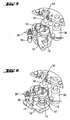
- Fig. 1 shows a fuse device 2 for an igniter with a housing 4, in the upper part of an electronic control unit 6 and including a firing chain 8 is arranged, which comprises a first and a second ignition means 10 and 14, respectively.
- the ignition chain 8 includes a detonator as a first ignition means 10 in a center axis of the igniter, wherein the center axis with respect to a rotation about a direction of flight 12 can be seen.
- an ignition amplifier is arranged as a second ignition means 14, which is aligned on an underside of the overlying detonator for receiving ignition energy from there.
- a barrier 16 which at their in Fig.
- FIG. 1 shown position a passage between the ignition means 10, 14 blocked.
- a pin 18 of a double pin system 20 is shown cut, which is pressed by a spring 22 in the direction of flight 12.
- the double pin system 20 is part of a first securing means 24 for locking the barrier 16 in its securing position.
- a second securing means 26 is shown, which is designed as a force element.
- Fig. 2 is the barrier 16 shown from below, with "up” in the direction of flight 12 and “down” opposite to the direction of flight 12 can be seen.
- Fig. 3 shows the ignition chain 8 in its safety.
- a zone 36 of the barrier blocks a gap between the two ignition means 10, 14 by filling the gap. The blockage is achieved by blocking a passage between the end of the first firing means 10 facing the second firing means 14 and the end of the second firing means 14 facing the first firing means 10 so that any direct line between them Ends through the barrier 16 runs.
- the barrier 16 is at a pivot point 38 by a in Fig. 2 held bolts 39 and prevented by a holding member 40 of the force element 26 from being able to pivot radially outwardly in a release movement. As in Fig. 2 can be seen, the barrier 16 is also applied to the second bolt 18, by which it is prevented from, in Fig. 2 to pivot clockwise in the release movement.
- the ignition chain 8 is interrupted by the barrier 16.
- the locking of the barrier 16 takes place on the one hand directly by the force element 26 and the other by the second pin 18 and thus corresponds to the requirement STANAG 4187th
- the second pin 18 is in turn locked by the first pin 30, as a ball 42 between the pin 18th , 30 prevents a translational movement of the second pin 18.
- the ball 42 is disposed in a groove 44 of the second pin 18 and would have to be pushed out upon movement of the second pin 18 down from the groove 44. This is prevented by the first pin 30, which blocks the outward movement of the ball 42 from the groove 44.
- the Entommesvorgang begins immediately after a launch of the projectile, part of which is the safety device 2. Due to the high acceleration of the safety device 2 when shooting in the direction of flight 12, the two bolts 18, 30 by their inertia relative to eg Barrier 16 to the rear and against the spring forces of the springs 22, 28 pressed. However, a movement of the second bolt 18 is initially blocked by the ball 42. However, the first pin 30 is free in its downward movement and is inserted in the in Fig. 4 pressed position shown. Now, the ball 42 is pushed out of the groove 44 and into a taper 46 of the first pin 30 by the inertial force of the second pin 18, so that the ball 42 releases downward movement of the second pin 18, as in FIG Fig. 4 is shown.
- the locking spring 32 engages behind an undercut 47 in the second pin 18 and thus blocks a return movement of the second pin 18 in the locking position.
- a contact element 48 in the form of a pin is moved out of a contact unit 50, so that an electrical contact in the contact unit 50 is interrupted. This is registered by the control unit 6 and used to control at least one further unlocking action.
- an unlocking means 52 designed as a spring is loaded to move the barrier 16 into its in-focus position by tensioning the spring.
- loading means 54 slides along an inclined surface 56 of the second bolt 18 and - by the inclined surface 56 down, ie in the unlocking of the second bolt 18, is moved - stretched and thus loaded.
- the loaded unlocking means 52 now exerts a pressure on the barrier 16 in its armed position, which remains held by the still locked second securing means 26, so that the barrier 16 is not yet moved by the pressure.
- the sequence of an unlocking program is started in the control unit 6.
- a predetermined unlocking parameter e.g. to a back pressure or a centrifugal force - and thus to a spin - or a pressure generated by a surcharge.
- the centrifugal force can be measured by pressing in or against the securing device 2 an element against a spring pressure to the outside and so against a contact and the element closes this.
- Other electrically interrogated sensors 57 connected to the control unit 6 are also conceivable.
- unlocking parameter stored in the control unit 6 or selected by the control unit 6 reaches a predetermined or from the control unit 6 fixed value, it is controlled by another unlocking action. It is also conceivable, the unlocking action by a timer and without sensor to control.
- the unlocking action will be in the in Fig. 5 shown embodiment completed by the second securing means 26.
- the securing means 26 is controlled by the control unit 6 and comprises a charging means with a pyrotechnic charge, which is now electrically ignited.
- a retaining element 58 in the form of a bolt which is provided for holding the barrier 16, blasted from the remaining securing means 26.
- a vent opening 60 is present in the igniter 2 ( Fig. 1 ), can escape through the displaced by the retaining element air and possibly explosive gases of the explosive charge.
- the charging means may have a charge in the form of a tensioned spring which is released by the unlocking action.
- Other forms of stored energy are also conceivable.
- the barrier 16 can perform its release movement and take its focus, which in Fig. 6 is shown.
- the release movement can be effected here by the Entriegelstoff 52 that the barrier pushes outward, or caused by centrifugal forces generated by swirl, which are supported by Entriegelstoff 52 only. A stop stops the release movement.
- the barrier 16 In its armed position, the barrier 16 is held by the spring 34, which in Fig. 7 is shown. It snaps behind the barrier and holds it in place, preserving its focus status.
- the barrier 16 With the release movement, the barrier 16 is removed from a gap 62 between the ignition means 10, 14 so that it is released. Now, an explosive energy can be transmitted from the first ignition means 10 to the second ignition means 14. Ignition of the first ignition means 10 is controlled by the control unit 6 according to programmable parameters and values of the parameters, e.g. by time, route or surcharge.
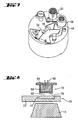
- Fig. 8 shows the two ignition means 10, 14 and the barrier 16 in the space 62 in a schematic sectional view.
- the first ignition means 10 comprises in a housing 64, one or more pyrotechnic charges 66, which by the Control unit 6 controlled ignition contacts 68 can be ignited electrically.
- a cover-shaped projectile 70 is blasted down at very high speed. If the barrier 16 is removed from the gap 62, the projectile 70 hits the second ignition means 14 and transfers ignition energy in the form of kinetic energy to the second ignition means 14, by which it is ignited.
- the barrier 16 In the case of a malfunction of the safety device, in particular a faulty detonation of the first ignition means 10, it is the task of the barrier 16 to prevent this transfer of ignition energy.
- it comprises a zone 71 of a hard metal, e.g. a carbide from the material group K10 of ISO standard 513, which is adapted in such a way to the first ignition means 10 that it has a sufficient hardness to intercept the projectile 70.
- the zone 71 adjoins another zone 72, which has a softer and more malleable metal.
- the cemented carbide is embedded in the zone 72 of softer metal.
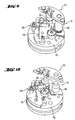
- FIGS. 9 and 10 show a further embodiment of a safety device 74 for a detonator.
- the following description is essentially limited to the differences from the exemplary embodiment in the preceding figures, to which reference is made with regard to features and functions that remain the same. Substantially identical components are basically numbered with the same reference numerals.
- Fig. 9 is the securing device 74 in its security and in Fig. 10 shown in their focus.
- the securing device 74 accommodates a barrier 76, whose release movement proceeds as described above, but in contrast to the barrier 16 carries the first ignition means 10.
- the first ignition means 10 is arranged outside the center axis, so that a faulty detonation directs the ignition energy into a holding plate 78 and does not reach the second ignition means 14.
- the barrier 76 blocks a gap between the ignition means 10, 14 by at least partially filling it. Only in the armed position is the first ignition means 10 in the center axis and thus arranged directly above the second ignition means 14 and directed thereto, so that the ignition energy can be transmitted and the ignition chain 8 is not interrupted.
Abstract
Description
Die Erfindung geht aus von einer Sicherungseinrichtung für einen Zünder, umfassend eine Zündkette mit einem Zündmittel und einer Barriere, die in ihrer Sicherstellung von einem ersten Sicherungsmittel und einem vom ersten unabhängigen zweiten Sicherungsmittel verriegelt ist, die zu einer Entriegelaktion aufgrund zwei voneinander unabhängiger physikalischer Entsicherungsparameter vorgesehen sind.The invention relates to a safety device for an igniter, comprising a detonating chain with an ignition means and a barrier, which is locked in its Sicherstellung by a first securing means and a first independent second securing means provided for an unlocking action due to two independent physical Entsicherungsparameter are.
Eine Sicherungseinrichtung für einen Zünder dient dazu, eine unabsichtliche Aktivierung einer Hauptladung einer Explosionsvorrichtung zu verhindern, wobei jedoch eine Aktivierung der Hauptladung nach einer Entsicherung möglich sein soll. Die Sicherungseinrichtung ist hierfür Bestandteil eines Zünders zum Zünden der Hauptladung, der mit einer Zündkette aus zwei oder mehr Zündmitteln versehen ist. Zum Zünden der Hauptladung wird zunächst das erste Zündmittel aktiviert, z.B. ein anstichempfindlicher Minidetonator, der von einem mechanischen Mittel zum Zünden angestochen wird. Explosionsenergie des ersten Zündmittels wird durch eine entsprechende Anordnung der ersten beiden Zündmittel auf das zweite Zündmittel übertragen, der als Zündverstärker ausgeführt sein kann. Dieser kann seine Explosionsenergie auf eine Ausgangsladung oder Hauptladung übertragen.A safety device for an igniter is used to prevent inadvertent activation of a main charge of an explosion device, but an activation of the main charge after a release should be possible. The safety device is part of a detonator for igniting the main charge, which is provided with a detonating chain of two or more ignition means. To ignite the main charge, first the first ignition means is activated, e.g. a puncture-sensitive mini-detonator that is pierced by a mechanical means for firing. Explosive energy of the first ignition means is transmitted by a corresponding arrangement of the first two ignition means to the second ignition means, which may be designed as a booster. This can transfer its explosive energy to an initial charge or main charge.
Zum Unterbrechen der Zündkette ist es aus der
Um auch kleinere Geschosse mit sicheren Zündern ausstatten bzw. mehr Baugruppen in großen Zündern unterbringen zu können, ist es wünschenswert, eine kleine Sicherungseinrichtung ohne Verlust an Sicherheit zur Verfügung stellen zu können.In order to equip smaller floors with safe detonators or accommodate more modules in large detonators, it is desirable to be able to provide a small security device without loss of security can.
Diese Aufgabe wird durch eine Sicherungseinrichtung der eingangs genannten Art gelöst, bei der die Zündkette ein zweites Zündmittel umfasst und die Barriere in einer Sicherstellung einen Zwischenraum zwischen den beiden Zündmitteln blockiert und durch eine den Zwischenraum freigebende Freigabebewegung in eine Scharfstellung bringbar ist. Das Vorsehen der beiden unabhängigen Sicherungsmittel gewährleistet ein hohes Maß an Sicherheit. Das Blockieren des Zwischenraums kann mit einem kompakten Bauteil erreicht werden.This object is achieved by a safety device of the type mentioned, in which the ignition chain comprises a second ignition means and the barrier blocks a gap between the two ignition means in a security and can be brought into a focus position by a release movement releasing the gap. The provision of the two independent securing means ensures a high degree of security. The blocking of the gap can be achieved with a compact component.
Die Entsicherungsparameter sind zweckmäßigerweise physikalisch voneinander unabhängig, so dass die Entriegelaktion von physikalisch voneinander unabhängigen Parametern, z.B. Kräften, ausgelöst werden können. Diese können eine Beschleunigung, ein Drall, ein Staudruck, eine Zeit nach einem Abschuss oder ein Aufschlagdruck sein. Das Blockieren kann erreicht werden, indem die Barriere in dem Zwischenraum angeordnet ist und diesen zumindest teilweise ausfüllt. Die Barriere gibt mit ihrer Freigabebewegung den Zwischenraum zwischen den Zündmitteln frei. Hierbei kann die Barriere aus dem Zwischenraum entfernt werden oder so verändert werden, dass der Zwischenraum frei wird, z.B. indem die Barriere im Zwischenraum von einer waagerechten in eine senkrechte Position verschwenkt wird. Der freigegebene Zwischenraum muss nicht der gesamte Zwischenraum zwischen den Zündmitteln sein.The arming parameters are desirably physically independent of each other such that the unlocking action is dependent on physically independent parameters, e.g. Forces, can be triggered. These can be an acceleration, a spin, a dynamic pressure, a time after a launch or an impact pressure. The blocking can be achieved by placing the barrier in the gap and at least partially filling it. The barrier releases the space between the ignition means with its release movement. In this case, the barrier can be removed from the gap or changed so that the gap is vacant, e.g. by pivoting the barrier in the intermediate space from a horizontal to a vertical position. The shared gap does not have to be the entire gap between the firing means.
Die Zündmittel können Explosionsladungen sein, wobei die Zündkette neben den beiden Zündmitteln noch ein weiteres Zündmittel umfassen kann, das in der Zündkette vor, insbesondere hinter den beiden Zündmitteln angeordnet ist. Die Barriere dient zum Ausnehmen und/oder Umlenken von Zündenergie des ersten Zündmittels derart, dass ein Zünden des zweiten Zündmittels durch Zündenergie des ersten Zündmittels zuverlässig unterbunden ist. Die Sicherungsmittel dienen zum insbesondere mechanischen Verriegeln der Barriere derart, dass eine Bewegung der Barriere von ihrer Sicherstellung in die Scharfstellung zuverlässig unterbunden wird. Durch eine Entriegelaktion kann die Barriere vom entsprechenden Sicherungsmittel in der Weise freigegeben werden, dass sie in die Scharfstellung beweglich ist, entweder z.B. durch Trägheit selbständig, oder angetrieben von einem Bewegungsmittel.The ignition means may be explosive charges, wherein the ignition chain in addition to the two ignition means may comprise a further ignition means, which is arranged in the ignition chain before, in particular behind the two ignition means. The barrier serves to exclude and / or redirect ignition energy of the first ignition means such that ignition of the second ignition means is reliably prevented by ignition energy of the first ignition means. The securing means are used in particular for mechanically locking the barrier in such a way that movement of the barrier from its securing into the armed position is reliably prevented. By unlocking the barrier can be released from the corresponding securing means in such a way that it is movable in the focus, either for example, by inertia independently, or powered by a means of movement.
In einer vorteilhaften Ausgestaltung der Erfindung verbleiben die Zündmittel bei einer Freigabebewegung zueinander ruhend. Es muss kein Raum zum Verschieben eines Zündmittels ausgespart bleiben, wodurch die Sicherungseinrichtung kompakt gebaut werden kann. Die beiden Zündmittel verbleiben bei der Freigabebewegung zweckmäßigerweise nicht nur zueinander sondern auch zu einem Gehäuse ruhend.In an advantageous embodiment of the invention, the ignition means remain at a release movement to each other dormant. There is no need to leave room for moving an ignition means, whereby the safety device can be made compact. The two ignition means remain in the release movement expediently not only to each other but also to a housing dormant.
In einer weiteren Ausführungsform der Erfindung ist das erste Sicherungsmittel zur Umsetzung des Entsicherungsparameters unmittelbar mechanisch in die Entriegelaktion vorgesehen. Es kann unabhängig von einer elektronischen Steuerung und somit günstig und robust entriegelt werden. Zweckmäßigerweise dient das erste Sicherungsmittel dazu, unmittelbar Energie eines Entsicherungsparameters aufzunehmen, insbesondere durch eigene Trägheit, und mechanisch in die Entriegelaktion umzusetzen.In a further embodiment of the invention, the first securing means for implementing the arming parameter is provided directly mechanically in the unlocking action. It can be unlocked independently of an electronic control and thus cheap and robust. Advantageously, the first securing means serves to directly absorb energy of a release parameter, in particular by its own inertia, and to convert it mechanically into the unlocking action.
Eine hohe Variabilität beim Auslösen der Entriegelaktion kann durch eine elektronische Steuereinheit zum Auslösen der Entriegelaktion des zweiten Sicherungsmittels erreicht werden. Das Auslösen ist nicht auf ein Vorliegen von Kräften angewiesen, sondern kann frei gesteuert werden, wodurch eine hohe Vorrohrsicherheit erreichbar ist. So kann eine Aktivierung der Zündkette beispielsweise auf einen festgelegten Zeitraum nach einem Abschuss beschränkt werden, so dass ein Geschoss nicht unmittelbar nach Verlassen eines Abschussrohrs zünden kann. Oder es kann ein Staudruck bzw. eine Anströmung über die Zeit integriert und daraus auf eine Flugstrecke geschlossen werden, so dass ein Zünden erst eine Strecke weit vom Abschussrohr zugelassen wird.A high variability in triggering the unlocking action can be achieved by an electronic control unit for triggering the unlocking action of the second securing means. The triggering is not dependent on the presence of forces, but can be freely controlled, whereby a high Vorrohr security can be achieved. For example, activation of the detonating chain may be restricted to a specified period of time after a launch so that a projectile can not fire immediately after leaving a launching tube. Or it can be integrated over time a back pressure or a flow and be closed on a route, so that an ignition is only allowed a distance from the launch tube.
Die Entriegelaktion kann ein Bewegen eines Mikromotors sein, der die Freigabebewegung der Barriere antreibt. Besonders vorteilhaft ist es jedoch, wenn das zweite Sicherungsmittel dazu vorgesehen ist, die Barriere durch die Entriegelaktion mechanisch zur Durchführung der Freigabebewegung freizugeben. Auf einen Motor kann verzichtet werden und die Sicherungseinrichtung kann einfach und kompakt gehalten bleiben. Durch das Freigeben kann sich die Barriere mit der Entriegelaktion selbstständig bewegen, beispielsweise durch Fliehkraft nach radial außen gezogen werden, oder von einem Entriegelmittel, z.B. einer Feder, angetrieben bewegen. Die Entriegelaktion und die Freigabebewegung können unterschiedliche Vorgänge sein, wodurch eine hohe Sicherheit erreichbar ist.The unlock action may be a movement of a micromotor that drives the release movement of the barrier. However, it is particularly advantageous if the second securing means is provided to release the barrier by the unlocking action mechanically to carry out the release movement. An engine can be dispensed with and the safety device can be kept simple and compact. By releasing the barrier can move independently with the Entriegelaktion, for example, be pulled by centrifugal force radially outward, or by a Entriegelmittel, such as a spring driven move. The Entriegelaktion and the release movement can be different processes, whereby a high level of security can be achieved.
Vorteilhafterweise umfasst die Sicherungseinrichtung eine elektronische Steuerung, die zur Steuerung der Entriegelaktion von zumindest eines der Sicherungsmittel vorbereitet ist. Die Steuerung kann wiederum mit einem Sensor zum Sensieren von einem der Entsicherungsparameter verbunden sein. Wird eine vorgegebener Wert des Entsicherungsparameters erreicht, z.B. eine vorgegebene Stärke eines Dralls, so kann die Steuereinheit die Entriegelaktion veranlassen.Advantageously, the securing device comprises an electronic control which is prepared for controlling the unlocking action of at least one of the securing means. The controller may in turn be connected to a sensor for sensing one of the arming parameters. When a predetermined value of the arming parameter is reached, e.g. a predetermined amount of twist, the control unit may initiate the unlocking action.
Vorteilhafterweise ist die elektronische Steuerung mit zwei Sensoren zum Sensieren von zwei verschiedenen Entsicherungsparametern verbunden und zur Steuerung der Entriegelaktion des zweiten Sicherungsmittels anhand beider Entsicherungsparameter vorgesehen. Die Sicherungseinrichtung kann universell eingesetzt werden und z.B. je nach Verwendung auf die Verarbeitung eines oder beider Entsicherungsparameter programmiert werden. Wird die Sicherungseinrichtung beispielsweise in einem mit Drall versehenen Geschoss verwendet, so kann die Steuerung auf die Verarbeitung der Daten desjenigen Sensors programmiert werden, der den Drall sensiert. Wird die Sicherungseinrichtung in einem Geschoss ohne Drall verwendet, kann die Steuerung auf die Verarbeitung von Daten eines anderen Sensors programmiert werden, beispielsweise eines Staudrucksensors. Es ist ebenfalls möglich, die Daten beider Sensoren zu verarbeiten und so die Entriegelaktion komplexer zu steuern. Die beiden Entsicherungsparameter sind zweckmäßigerweise von dem Entsicherungsparameter des ersten Sicherungsmittels verschieden.Advantageously, the electronic control is connected to two sensors for sensing two different Entsicherungsparametern and provided for controlling the Entriegelaktion the second securing means based on both Entsicherungsparameter. The security device can be used universally and e.g. depending on the application, can be programmed to process one or both arming parameters. If the security device is used, for example, in a swirled projectile, then the controller can be programmed to process the data of that sensor which senses the swirl. If the safety device is used on a non-spinning projectile, the controller can be programmed to process data from another sensor, such as a back pressure sensor. It is also possible to process the data from both sensors to control the unlocking action more complexly. The two unlocking parameters are expediently different from the unlocking parameter of the first securing means.
In einer vorteilhaften Weiterbildung der Erfindung umfasst das zweite Sicherungsmittel ein Ladungsmittel zum Tätigen der Entriegelaktion durch eine Entladung. Das zweite Sicherungsmittel kann hierdurch kompakt gehalten sein. Das Ladungsmittel kann jedes Mittel sein, das zur Speicherung einer mechanischen, chemischen oder elektrischen Ladung in der Lage ist. In einer einfachen Variante ist die Ladung eine Feder, durch die eine Entriegelaktion angetrieben wird. Besonders kompakt kann das Sicherungsmittel sein, wenn die Ladung eine chemische Ladung ist, z.B. in Form einer pyrotechnischen Ladung. Alternativ oder zusätzlich kann das Ladungsmittel zum Ansammeln einer Ladung ausgebildet sein, z.B. in Form eines Drucks, der von einem Staudruck gebildet sein kann, der ein Halteelement, z.B. einen Bolzen wegdrückt und so die Barriere entriegelt.In an advantageous development of the invention, the second securing means comprises a loading means for actuating the unlocking action by means of a discharge. The second securing means can thereby be kept compact. The charging means may be any means capable of storing a mechanical, chemical or electrical charge. In a simple variant, the load is a spring through which an unlocking action is driven. The securing means may be particularly compact if the charge is a chemical charge, e.g. in the form of a pyrotechnic charge. Alternatively or additionally, the charging means may be configured to accumulate a charge, e.g. in the form of a pressure, which may be formed by a dynamic pressure, comprising a retaining element, e.g. pushes a bolt away and unlocks the barrier.
Die Entriegelaktion kann besonders einfach und das Sicherungsmittel besonders kompakt sein, wenn die Entladung dazu vorgesehen ist, ein Halteelement, das zum Halten der Barriere vorgesehen ist, von einem anderen Element des Sicherungsmittels zu trennen und abzuwerfen. So kann ein Bolzen abgeworfen, insbesondere abgesprengt werden, wodurch eine zuvor feste Verbindung auf einfache Weise gelöst werden kann.The unlocking action can be particularly simple and the securing means particularly compact, when the discharge is intended, a holding element, which is intended to hold the barrier, from another element of the securing means to separate and throw off. Thus, a bolt can be dropped, in particular blasted, whereby a previously solid connection can be solved in a simple manner.
In einer weiteren Ausführungsvariante der Erfindung weist das erste Sicherungsmittel ein Doppelbolzensystem auf. Dieses einfache System ist durch die beiden nur in einer Kette aktivierbaren Bolzen besonders sicher bei der Erfassung einer länger andauernden Beschleunigung als Entsicherungsparameter.In a further embodiment variant of the invention, the first securing means has a double-bolt system. This simple system is particularly safe with the two bolts, which can only be activated in one chain, when detecting a longer lasting acceleration than arming parameters.
Erfolgt die Freigabebewegung der Barriere nach radial außen durch einen Drall, so kann die Sicherungseinrichtung besonders einfach gehalten sein. Umfasst die Sicherungseinrichtung ein Entriegelmittel zum Bewegen der Barriere in die Scharfstellung, so kann die Sicherungseinrichtung auch in Geschossen ohne Drall verwendet werden. Ein besonders einfaches Entriegelmittel ist eine Feder.If the release movement of the barrier radially outward by a twist, so the safety device can be kept very simple. If the securing device comprises unlocking means for moving the barrier into the armed position, the securing device can also be used in projectiles without swirling. A particularly simple Entriegelmittel is a spring.
Um ein hohes Maß an Sicherheit vor einer unbeabsichtigten Entriegelung der Barriere zu erhalten, sollte das Entriegelmittel, also z.B. die Feder, nicht grundsätzlich in einem Zustand sein, der eine Bewegung der Barriere erlaubt, sondern erst dann in der Lage sein, die Barriere zu bewegen, wenn ein Entsicherungskriterium erfüllt ist. Ein Entsicherungskriterium ist eine Entriegelaktion eines der Sicherungsmittel. Ist das erste Sicherungsmittel dazu vorgesehen, das Entriegelmittel durch eine Entriegelaktion zu laden, so kann eben jene Sicherheit erreicht werden. Das Laden kann ein Spannen sein, z.B. einer Feder.In order to obtain a high level of security against inadvertent unlocking of the barrier, the unlocking means, e.g. the spring is not fundamentally in a condition permitting movement of the barrier, but will only be able to move the barrier when a release criterion is met. A Entsicherungskriterium is an unlocking action of one of the securing means. If the first securing means is provided to load the unlocking means by an unlocking action, then just that security can be achieved. The loading may be cocking, e.g. a spring.
Eine kompakte und robuste Ladung des Entriegelmittels kann erreicht werden, wenn das erste Sicherungsmittel eine zu einer Entriegelrichtung schräge Fläche aufweist, die bei ihrer Bewegung in Entriegelrichtung die Ladung durch eine Bewegung eines Lademittels entlang der Fläche bewirkt. In einer besonders einfachen und fehlerunanfälligen Ausführungsform wird die Fläche entlang eines Federarms geführt, der so gespannt wird.A compact and robust loading of Entriegelmittels can be achieved if the first securing means has an inclined to an unlocking surface, which causes the movement in the unlocking the charge by a movement of a loading means along the surface. In a particularly simple and error-prone embodiment, the surface is guided along a spring arm, which is so tense.
Die Kompaktheit der Sicherungseinrichtung kann weiter gesteigert werden, wenn das erste Zündmittel besonders klein ist und dennoch in seiner Kraft ausreicht, um das zweite Zündmittel zu zünden. Dies kann realisiert werden, wenn das erste Zündmittel ein Geschoss zum Zünden des zweiten Zündmittels umfasst. Die Zündenergie des ersten Zündmittels wird durch kinetische Energie des Geschosses auf das zweite Zündmittel übertragen, das durch die Druckwelle des auftreffenden Geschosses zur Zündung gebracht werden kann. Das Geschoss kann ein Bolzen oder ein Deckel des ersten Zündmittels sein, der durch eine Detonation des ersten Zündmittels in Richtung zum zweiten Zündmittel abgesprengt wird.The compactness of the safety device can be further increased if the first ignition means is particularly small and yet sufficient in its force to ignite the second ignition means. This can be realized if the first ignition means comprises a projectile for igniting the second ignition means. The ignition energy of the first ignition means is transmitted by kinetic energy of the projectile to the second ignition means, which by the pressure wave of the impinging projectile Ignition can be brought. The projectile may be a bolt or a lid of the first ignition means, which is blasted off by a detonation of the first ignition means in the direction of the second ignition means.
Die Aufgabe der Barriere besteht darin, die Zündkette auch bei einer Fehlzündung des ersten Zündmittels zuverlässig zu unterbrechen, so dass die Zündenergie des ersten Zündmittels möglichst gar nicht das zweite Zündmittel erreicht. Insbesondere bei der Übertragung von Zündenergie in Form von kinetischer Energie muss das erste Zündmittel nicht vollständig vom zweiten Zündmittel abgeschirmt werden, da kein in seiner Bewegung freier Feuerstrahl die Zündenergie überträgt, und die Barriere kann kompakt sein. Allerdings sind besonders hohe Anforderungen hinsichtlich der Stabilität an die Barriere gestellt. Diesen Anforderungen kann genügt werden, wenn die Barriere zwei verschiedene Metalle umfasst, wodurch zwei unterschiedliche Eigenschaften von Metallen gemeinsam zum Einsatz kommen können, z.B. eine hohe Bruchfestigkeit in Verbindung mit einer großen Härte. Besonders sicher ist die Abschirmfunktion der Barriere, wenn sie zwischen den Zündmitteln eine Zone härteren Metalls und außerhalb dieser Zone eine weitere Zone weicheren Metalls aufweist. Besonders geeignet ist als härteres Metall ein WC-Hartmetall, mit einem Anteil an Wolfram-Carbid von über 90%. Ebenfalls vorteilhaft ist ein Hartmetall mit einer Härte über 90 nach Rockwell oder über 1480 nach Vickers, insbesondere mit einer Härte über 91,5 nach Rockwell oder über 1700 nach Vickers. Bei solchen Hartmetallen ist jedoch die Biegefestigkeit mit ggf. unter 2000 N/mm2 nicht sehr hoch, außerdem sind sie recht kostspielig und aufwendig in der Bearbeitung für eine Formgebung für die gesamte Barriere, so dass die Einbettung des härteren Metalls in das weichere Metall vorgeschlagen wird. Dieses kann sich durch eine geringere Härte als das härtere Metall auszeichnen, insbesondere auch durch eine einfachere Spanbarkeit zur einfacheren Bearbeitung.The object of the barrier is to reliably interrupt the ignition chain even in the case of a misfire of the first ignition means, so that the ignition energy of the first ignition means does not possibly reach the second ignition means. In particular, in the transmission of ignition energy in the form of kinetic energy, the first ignition means does not have to be completely shielded by the second ignition means, since no free jet of fire propagates the ignition energy, and the barrier can be compact. However, particularly high stability requirements are placed on the barrier. These requirements can be met if the barrier comprises two different metals, whereby two different properties of metals can be used together, for example a high breaking strength combined with a high degree of hardness. The shielding function of the barrier is particularly safe if it has a zone of harder metal between the ignition means and another zone of softer metal outside this zone. Particularly suitable as a harder metal is a WC hard metal, with a tungsten carbide content of over 90%. Also advantageous is a hard metal with a hardness over 90 Rockwell or 1480 Vickers, in particular with a hardness over 91.5 Rockwell or about 1700 Vickers. In such hard metals, however, the flexural strength with possibly less than 2000 N / mm 2 is not very high, also they are quite expensive and expensive to process for a shaping of the entire barrier, so that the embedding of the harder metal proposed in the softer metal becomes. This can be characterized by a lower hardness than the harder metal, in particular by a simpler machinability for easier processing.
Die Erfindung wird anhand von Ausführungsbeispielen näher erläutert, die in den Zeichnungen dargestellt sind.The invention will be explained in more detail with reference to exemplary embodiments, which are illustrated in the drawings.
Es zeigen:
- Fig. 1
- eine Sicherungseinrichtung in einer Schnittdarstellung,
- Fig. 2
- eine Detail der Sicherungseinrichtung aus
Fig. 1 in einer Sicht von unten, - Fig. 3
- eine Zündkette der Sicherungseinrichtung aus
Fig. 1 in einer schematischen Darstellung, - Fig. 4
- die Zündkette nach einer ersten Entriegelaktion,
- Fig. 5
- die Zündkette nach einer weiteren Entriegelaktion,
- Fig. 6
- die Zündkette mit einer Barriere nach einer Freigabebewegung,
- Fig. 7
- die durch eine Feder verriegelte Barriere von unten,
- Fig. 8
- eine schematische Schnittdarstellung durch zwei Zündmittel und der zwischen ihnen angeordneten Barriere,
- Fig. 9
- eine alternative Zündkette mit einem verschiebbaren Zündmittel und
- Fig. 10
- die Zündkette aus
Fig. 9 mit einer Barriere in Scharfstellung.
- Fig. 1
- a safety device in a sectional view,
- Fig. 2
- a detail of the safety device
Fig. 1 in a view from below, - Fig. 3
- a firing chain of the security device
Fig. 1 in a schematic representation, - Fig. 4
- the firing chain after a first unlocking action,
- Fig. 5
- the detonating chain after another unlocking action,
- Fig. 6
- the firing chain with a barrier after a release movement,
- Fig. 7
- the spring-locked barrier from below,
- Fig. 8
- a schematic sectional view through two ignition means and the barrier arranged between them,
- Fig. 9
- an alternative ignition chain with a displaceable ignition means and
- Fig. 10
- the ignition chain off
Fig. 9 with a barrier in focus.
In
Die Barriere 16 wird in einem Drehpunkt 38 durch einen in
In der Sicherstellung wird die Zündkette 8 von der Barriere 16 unterbrochen. Die Verriegelung der Barriere 16 erfolgt zum einen direkt durch das Kraftelement 26 und zum anderen durch den zweiten Bolzen 18 und entspricht somit der Vorschrift STANAG 4187. Der zweite Bolzen 18 ist wiederum durch den ersten Bolzen 30 verriegelt, da eine Kugel 42 zwischen den Bolzen 18, 30 eine Translationsbewegung des zweiten Bolzens 18 verhindert. Die Kugel 42 ist in einer Rille 44 des zweiten Bolzens 18 angeordnet und müsste bei einer Bewegung des zweiten Bolzens 18 nach unten aus der Rille 44 herausgedrückt werden. Das wird durch den ersten Bolzen 30 verhindert, der die Herausbewegung der Kugel 42 aus der Rille 44 sperrt.In ensuring the
Anhand der
Durch die Entsicherungsbewegung des zweiten Bolzens 18 nach unten werden mehrere weitere Entsicherungsvorgänge bewirkt. Zunächst rastet die Sperrfeder 32 hinter einen Hinterschnitt 47 im zweiten Bolzen 18 ein und sperrt so eine Rückbewegung des zweiten Bolzens 18 in die Verriegelstellung. Außerdem wird ein Kontaktelement 48 in Form eines Stifts aus einer Kontakteinheit 50 bewegt, so dass ein elektrischer Kontakt in der Kontakteinheit 50 unterbrochen wird. Dies wird von der Steuereinheit 6 registriert und zur Steuerung von zumindest einer weiteren Entriegelaktion verwendet. Des Weiteren wird ein als Feder ausgeführtes Entriegelmittel 52 zum Bewegen der Barriere 16 in ihre Scharfstellung geladen, indem die Feder gespannt wird. Dies geschieht, indem ein Arm der Feder, im Folgenden als Lademittel 54 bezeichnet, an einer schrägen Fläche 56 des zweiten Bolzens 18 entlang gleitet und - indem die schräge Fläche 56 nach unten, also in die Entriegelrichtung des zweiten Bolzens 18, bewegt wird - gespannt und somit geladen wird. Das geladene Entriegelmittel 52 übt nun einen Druck auf die Barriere 16 in deren Scharfstellung aus, der jedoch durch das noch verriegelte zweite Sicherungsmittel 26 gehalten bleibt, so dass die Barriere 16 durch den Druck noch nicht bewegt wird.By the Entsicherungsbewegung the
Durch das Öffnen der Kontakteinheit 50 wird in der Steuereinheit 6 der Ablauf eines Entriegelprogramms gestartet. Durch das Entriegelprogramm können nun z.B. Daten eines Sensors 57 abgefragt werden, der auf einen vorbestimmten Entriegelparameter empfindlich ist, z.B. auf einen Staudruck oder eine Fliehkraft - und somit auf einen Drall - oder einen durch einen Aufschlag erzeugten Druck. Die Fliehkraft kann gemessen werden, indem in oder an der Sicherungsvorrichtung 2 ein Element gegen einen Federdruck nach außen und so gegen einen Kontakt gedrückt wird und das Element diesen schließt. Auch andere mit der Steuereinheit 6 verbundene elektrisch abgefragte Sensoren 57 sind denkbar.By opening the
Erreicht der in der Steuereinheit 6 hinterlegte oder von der Steuereinheit 6 ausgesuchte Entriegelparameter einen vorbestimmten oder von der Steuereinheit 6 festgelegten Wert, wird von ihr eine weitere Entriegelaktion gesteuert. Ebenfalls denkbar ist es, die Entriegelaktion durch eine Zeitschaltung und ohne Sensor zu Steuern.If the unlocking parameter stored in the
Die Entriegelaktion wird in dem in
Nachdem das Halteelement 58 abgesprengt wurde, kann die Barriere 16 ihre Freigabebewegung durchführen und ihre Scharfstellung einnehmen, die in
In ihrer Scharfstellung wird die Barriere 16 von der Feder 34 gehalten, die in
Mit der Freigabebewegung wird die Barriere 16 aus einem Zwischenraum 62 zwischen den Zündmitteln 10, 14 entfernt, so dass dieser freigegeben wird. Nun kann eine Sprengenergie vom ersten Zündmittel 10 auf das zweite Zündmittel 14 übertragen werden. Ein Zünden des ersten Zündmittels 10 wird von der Steuereinheit 6 gesteuert nach programmierbaren Parametern und Werten der Parameter, z.B. nach Zeit, Flugstrecke oder Aufschlag.With the release movement, the
Im Falle einer Fehlfunktion der Sicherungseinrichtung, insbesondere einer fehlerhaften Detonation des ersten Zündmittels 10, ist es die Aufgabe der Barriere 16, diesen Übertrag von Zündenergie zu verhindern. Dazu umfasst sie eine Zone 71 aus einem Hartmetall, z.B. ein Hartmetall aus der Werkstoffgruppe K10 der Norm ISO 513, das in der Weise auf das erste Zündmittel 10 angepasst ist, dass es eine genügende Härte aufweist, um das Geschoss 70 abzufangen. Um einen Bruch der Barriere 16 zu vermeiden, grenzt die Zone 71 an eine weitere Zone 72, die ein weicheres und verformbareres Metall aufweist. Insbesondere ist das Hartmetall in die Zone 72 weicheren Metalls eingebettet.In the case of a malfunction of the safety device, in particular a faulty detonation of the first ignition means 10, it is the task of the
Die
In
- 22
- Sicherungseinrichtungsafety device
- 44
- Gehäusecasing
- 66
- Steuereinheitcontrol unit
- 88th
- Zündketteignition chain
- 1010
- Zündmittelignition means
- 1212
- Flugrichtungflight direction
- 1414
- Zündmittelignition means
- 1616
- Barrierebarrier
- 1818
- Bolzenbolt
- 2020
- DoppelbolzensystemDouble-bolt system
- 2222
- Federfeather
- 2424
- Sicherungsmittelsecuring means
- 2626
- Sicherungsmittelsecuring means
- 2828
- Federfeather
- 3030
- Bolzenbolt
- 3232
- Sperrfederlocking spring
- 3434
- Sperrfederlocking spring
- 3636
- ZoneZone
- 3838
- Drehpunktpivot point
- 3939
- Bolzenbolt
- 4040
- Halteelementretaining element
- 4242
- KugelBullet
- 4444
- Rillegroove
- 4646
- Verjüngungrejuvenation
- 4747
- Hinterschnittundercut
- 4848
- KontakteinheitContact unit
- 5050
- KontakteinheitContact unit
- 5252
- EntriegelmittelEntriegelmittel
- 5454
- Lademittelloading equipment
- 5656
- Flächearea
- 5757
- Sensorsensor
- 5858
- Halteelementretaining element
- 6060
- Entlüftungsöffnungvent
- 6262
- Zwischenraumgap
- 6464
- Gehäusecasing
- 6666
- Ladungcharge
- 6868
- ZündkontakteIgnition Points
- 7070
- Geschossbullet
- 7171
- ZoneZone
- 7272
- ZoneZone
- 7474
- Sicherungseinrichtungsafety device
- 7676
- Barrierebarrier
- 7878
- HalteplatteRetaining plate
Claims (16)
dadurch gekennzeichnet,
dass die Zündkette (8) ein zweites Zündmittel (14) umfasst und die Barriere (16, 76) in einer Sicherstellung einen Zwischenraum (62) zwischen den beiden Zündmitteln (10, 14) blockiert und durch eine den Zwischenraum (62) freigebende Freigabebewegung in eine Scharfstellung bringbar ist.An igniter (2, 74) for an igniter, comprising a detonating chain (8) having an ignition means (10) and a barrier (16, 76) secured by a first securing means (24) and a second independent securing means (16). 26) provided for unlocking due to two independent physical arming parameters,
characterized,
that the firing chain (8) comprises a second firing means (14) and the barrier (16, 76) in a safeguard blocks a gap (62) between the two firing means (10, 14) and by a release movement in the gap (62) a focus can be brought.
dadurch gekennzeichnet,
dass die Zündmittel (10, 14) bei einer Freigabebewegung zueinander ruhend verbleiben.Securing device (2) according to claim 1,
characterized,
that the ignition means (10, 14) remain at rest during a release movement to each other.
dadurch gekennzeichnet,
dass das erste Sicherungsmittel (24) zur Umsetzung des Entsicherungsparameters unmittelbar mechanisch in die Entriegelaktion vorgesehen ist.Securing device (2, 74) according to claim 1 or 2,
characterized,
that the first securing means (24) is directly mechanically provided to implement the Entsicherungsparameters in the unlocking action.
gekennzeichnet
durch eine elektronische Steuereinheit (6) zum Auslösen der Entriegelaktion des zweiten Sicherungsmittels (26).Securing device (2, 74) according to one of the preceding claims,
marked
by an electronic control unit (6) for triggering the unlocking action of the second securing means (26).
dadurch gekennzeichnet,
dass das zweite Sicherungsmittel (26) dazu vorgesehen ist, die Barriere (16, 76) durch die Entriegelaktion mechanisch zur Durchführung der Freigabebewegung freizugeben.Securing device (2, 74) according to one of the preceding claims,
characterized,
in that the second securing means (26) is provided for mechanically releasing the barrier (16, 76) by the unlocking action for carrying out the release movement.
gekennzeichnet
durch eine elektronische Steuereinheit (6), die mit zwei Sensoren (57) zum Sensieren von zwei verschiedenen Entsicherungsparametern verbunden ist und zur Steuerung der Entriegelaktion des zweiten Sicherungsmittels (26) anhand beider Entsicherungsparameter vorgesehen ist.Securing device (2, 74) according to one of the preceding claims,
marked
by an electronic control unit (6) which is connected to two sensors (57) for sensing two different arming parameters and for controlling the unlocking action of the second securing means (26) by means of both arming parameters.
dadurch gekennzeichnet,
dass das zweite Sicherungsmittel (26) ein Ladungsmittel zum Tätigen der Entriegelaktion durch eine Entladung umfasst.Securing device (2, 74) according to one of the preceding claims,
characterized,
in that the second securing means (26) comprises a loading means for actuating the unlocking action by a discharge.
dadurch gekennzeichnet,
dass das Ladungsmittel eine pyrotechnische Ladung aufweist.Securing device (2, 74) according to claim 7,
characterized,
that the charge means comprises a pyrotechnic charge.
dadurch gekennzeichnet,
dass die Entladung dazu vorgesehen ist, ein Halteelement (58), das zum Halten der Barriere (16, 76) vorgesehen ist, von einem anderen Element des Sicherungsmittels (26) zu trennen und abzuwerfen.Securing device (2, 74) according to claim 7 or 8,
characterized,
in that the discharge is intended to separate and drop one holding element (58), which is provided for holding the barrier (16, 76), from another element of the securing means (26).
dadurch gekennzeichnet,
dass das erste Sicherungsmittel (24) ein Doppelbolzensystem (20) aufweist.Securing device (2, 74) according to one of the preceding claims,
characterized,
in that the first securing means (24) has a double-bolt system (20).
dadurch gekennzeichnet,
dass die Freigabebewegung der Barriere (16, 76) nach radial außen durch einen Drall erfolgt.Securing device (2, 74) according to one of the preceding claims,
characterized,
that the release movement of the barrier (16, 76) takes place radially outward by a twist.
gekennzeichnet
durch ein Entriegelmittel (52) zum Bewegen der Barriere (16, 76) in die Scharfstellung.Securing device (2, 74) according to one of the preceding claims,
marked
by an unlocking means (52) for moving the barrier (16, 76) into the in-focus position.
dadurch gekennzeichnet,
dass das erste Sicherungsmittel (24) dazu vorgesehen ist, das Entriegelmittel (52) durch eine Entriegelaktion zu laden.Securing device (2, 74) according to claim 12,
characterized,
that the first securing means (24) is provided to load the Entriegelmittel (52) by an unlocking action.
dadurch gekennzeichnet,
dass das erste Sicherungsmittel (24) eine zu einer Entriegelrichtung schräge Fläche (56) aufweist, die bei ihrer Bewegung in Entriegelrichtung die Ladung durch eine Bewegung eines Lademittels entlang der Fläche (56) bewirkt.Securing device (2, 74) according to claim 13,
characterized,
in that the first securing means (24) has an inclined surface (56) towards an unlocking direction, which in its movement in the unlocking direction causes the loading by a movement of a loading means along the surface (56).
dadurch gekennzeichnet,
dass das erste Zündmittel (10) ein Geschoss (70) zum Zünden des zweiten Zündmittels (14) umfasst.Securing device (2, 74) according to one of the preceding claims,
characterized,
in that the first ignition means (10) comprises a projectile (70) for igniting the second ignition means (14).
dadurch gekennzeichnet,
dass die Barriere (16, 76) zwischen den Zündmitteln (10, 14) eine Zone (71) härteren Metalls und außerhalb dieser Zone (71) eine weitere Zone (72) weicheren Metalls und aufweist.Securing device (2, 74) according to one of the preceding claims,
characterized,
in that the barrier (16, 76) between the ignition means (10, 14) comprises a zone (71) of harder metal and outside this zone (71) has a further zone (72) of softer metal and.
Applications Claiming Priority (1)
| Application Number | Priority Date | Filing Date | Title |
|---|---|---|---|
| DE102007054777A DE102007054777B3 (en) | 2007-11-16 | 2007-11-16 | Safety device for an igniter |
Publications (2)
| Publication Number | Publication Date |
|---|---|
| EP2060868A2 true EP2060868A2 (en) | 2009-05-20 |
| EP2060868A3 EP2060868A3 (en) | 2013-02-20 |
Family
ID=40303675
Family Applications (1)
| Application Number | Title | Priority Date | Filing Date |
|---|---|---|---|
| EP08019240A Ceased EP2060868A3 (en) | 2007-11-16 | 2008-11-04 | Safety device for a fuse |
Country Status (4)
| Country | Link |
|---|---|
| US (1) | US8381650B2 (en) |
| EP (1) | EP2060868A3 (en) |
| CA (1) | CA2639467C (en) |
| DE (1) | DE102007054777B3 (en) |
Cited By (5)
| Publication number | Priority date | Publication date | Assignee | Title |
|---|---|---|---|---|
| CN107121033A (en) * | 2017-06-27 | 2017-09-01 | 湖北三江航天红林探控有限公司 | A kind of electromagnet inertia composite rotors formula interrupter |
| CN107121034A (en) * | 2017-06-27 | 2017-09-01 | 湖北三江航天红林探控有限公司 | One kind hot melt alloy inertia composite rotors formula interrupter |
| CN107144187A (en) * | 2017-06-27 | 2017-09-08 | 湖北三江航天红林探控有限公司 | A kind of gunpowder inertia composite rotors formula interrupter |
| CN107144188A (en) * | 2017-06-27 | 2017-09-08 | 湖北三江航天红林探控有限公司 | A kind of electromagnetic confinement formula interrupter based on inertia |
| CN107152897A (en) * | 2017-06-27 | 2017-09-12 | 湖北三江航天红林探控有限公司 | A kind of inertial drive rotator type interrupter |
Families Citing this family (6)
| Publication number | Priority date | Publication date | Assignee | Title |
|---|---|---|---|---|
| DE102009058718B4 (en) * | 2009-12-17 | 2011-12-08 | Junghans Microtec Gmbh | Safety device for an igniter of a projectile |
| US20110297029A1 (en) * | 2010-06-06 | 2011-12-08 | Omnitek Partners Llc | Inertial igniters with safety pin for initiation with low setback acceleration |
| IL213830A (en) * | 2011-06-29 | 2017-07-31 | Rafael Advanced Defense Systems Ltd | Controlled pyrotechnic train |
| AU2012371687B2 (en) * | 2012-02-29 | 2016-03-03 | Scg Chemicals Co., Ltd. | High emissivity coating compositions and manufacturing processes therefore |
| DE102018004510B4 (en) | 2018-06-07 | 2020-06-18 | Diehl Defence Gmbh & Co. Kg | Ammunition with a device for generating an unlocking criterion for a fuse of the ammunition |
| CN110906800B (en) * | 2019-12-11 | 2022-02-18 | 湖北三江航天红林探控有限公司 | Combined type detonating device based on two pin pullers |
Citations (4)
| Publication number | Priority date | Publication date | Assignee | Title |
|---|---|---|---|---|
| GB508912A (en) * | 1937-06-30 | 1939-07-07 | Mefina Sa | Improvements in or relating to clockwork safety mechanism for explosive projectiles |
| US2737890A (en) * | 1942-11-09 | 1956-03-13 | Robert B Brode | Safety unit for explosive devices |
| US2960037A (en) * | 1952-01-23 | 1960-11-15 | Jr Harry Raech | Safety arming device for explosive missiles |
| US4691634A (en) | 1986-06-19 | 1987-09-08 | Motorola, Inc. | Electro-explosive safety and arming device |
Family Cites Families (22)
| Publication number | Priority date | Publication date | Assignee | Title |
|---|---|---|---|---|
| DE1074455B (en) * | 1960-01-28 | Dr Ing e h Helmut Junghans und Gebruder Junghans Aktiengesell schaft Schramberg (Wurtt) | On tinder | |
| US2516323A (en) * | 1943-05-01 | 1950-07-25 | James D Jordan | Safety gate |
| DE2643828C3 (en) | 1976-09-29 | 1980-09-11 | Gebrueder Junghans Gmbh, 7230 Schramberg | Detonator for bullets to be fired with little twist |
| GB2023778B (en) * | 1978-05-31 | 1982-04-15 | British Aerospace | Latch devices |
| SE442446B (en) * | 1980-09-25 | 1985-12-23 | Bofors Ab | TENDROR CIRCUIT WITH TWO RESTRICTIONS WITH PREDICTED TIMELINE FOR TRANSMISSION |
| US4662279A (en) * | 1985-09-23 | 1987-05-05 | Interdyne Service Corp. | Safing and arming device |
| US4744298A (en) * | 1986-05-09 | 1988-05-17 | Dragolyoub Popovitch | Safing and arming device and method |
| US4770096A (en) * | 1987-08-17 | 1988-09-13 | Honeywell Inc. | Safing and arming mechanism |
| DE3742575A1 (en) * | 1987-12-16 | 1989-07-06 | Junghans Gmbh Geb | ZENDER |
| DE3904091A1 (en) * | 1989-02-11 | 1990-08-16 | Honeywell Regelsysteme Gmbh | Safety device |
| US4938138A (en) * | 1989-08-07 | 1990-07-03 | Honeywell Inc. | Safing and arming mechanism with creep ribbon arming delay |
| DE3935180A1 (en) * | 1989-10-23 | 1991-04-25 | Junghans Gmbh Geb | PROTECTIVE DEVICE FOR A FLOOR IGNITION |
| US5067405A (en) * | 1990-04-12 | 1991-11-26 | Dragolyoub Popovitch | Safing and arming device |
| DE4030917C2 (en) * | 1990-09-29 | 1995-09-07 | Rheinmetall Ind Gmbh | Speed range depending on unlockable detonators for an explosive projectile |
| US5275107A (en) * | 1992-06-19 | 1994-01-04 | Alliant Techsystems Inc. | Gun launched non-spinning safety and arming mechanism |
| US5271327A (en) * | 1992-06-19 | 1993-12-21 | Alliant Techsystems Inc. | Elecro-mechanical base element fuze |
| ES2138474B1 (en) * | 1995-07-10 | 2000-10-01 | Garcia Jose Garcia | HIGH SECURITY SPLET AND HIGH EXPLOSION FOR MORTAR AND SMOOTH WEAPONS. |
| US5693906A (en) * | 1995-09-28 | 1997-12-02 | Alliant Techsystems Inc. | Electro-mechanical safety and arming device |
| DE19727002C2 (en) * | 1997-06-25 | 1999-12-16 | Rheinmetall W & M Gmbh | Safety device for detonators of swirl projectiles with a locking lever which can be pivoted by a detonator carrier |
| FR2786262B1 (en) * | 1998-11-23 | 2001-10-19 | Giat Ind Sa | DEVICE FOR ACTIVE PROTECTION OF A VEHICLE OR STRUCTURE WALL |
| DE10111714C1 (en) * | 2001-03-12 | 2002-10-10 | Nico Pyrotechnik | Detonator for a projectile to be fired from a tube with swirl |
| US6622629B2 (en) * | 2001-10-17 | 2003-09-23 | Northrop Grumman Corporation | Submunition fuzing and self-destruct using MEMS arm fire and safe and arm devices |
-
2007
- 2007-11-16 DE DE102007054777A patent/DE102007054777B3/en active Active
-
2008
- 2008-09-09 CA CA2639467A patent/CA2639467C/en active Active
- 2008-11-04 EP EP08019240A patent/EP2060868A3/en not_active Ceased
- 2008-11-05 US US12/265,321 patent/US8381650B2/en active Active
Patent Citations (4)
| Publication number | Priority date | Publication date | Assignee | Title |
|---|---|---|---|---|
| GB508912A (en) * | 1937-06-30 | 1939-07-07 | Mefina Sa | Improvements in or relating to clockwork safety mechanism for explosive projectiles |
| US2737890A (en) * | 1942-11-09 | 1956-03-13 | Robert B Brode | Safety unit for explosive devices |
| US2960037A (en) * | 1952-01-23 | 1960-11-15 | Jr Harry Raech | Safety arming device for explosive missiles |
| US4691634A (en) | 1986-06-19 | 1987-09-08 | Motorola, Inc. | Electro-explosive safety and arming device |
Cited By (8)
| Publication number | Priority date | Publication date | Assignee | Title |
|---|---|---|---|---|
| CN107121033A (en) * | 2017-06-27 | 2017-09-01 | 湖北三江航天红林探控有限公司 | A kind of electromagnet inertia composite rotors formula interrupter |
| CN107121034A (en) * | 2017-06-27 | 2017-09-01 | 湖北三江航天红林探控有限公司 | One kind hot melt alloy inertia composite rotors formula interrupter |
| CN107144187A (en) * | 2017-06-27 | 2017-09-08 | 湖北三江航天红林探控有限公司 | A kind of gunpowder inertia composite rotors formula interrupter |
| CN107144188A (en) * | 2017-06-27 | 2017-09-08 | 湖北三江航天红林探控有限公司 | A kind of electromagnetic confinement formula interrupter based on inertia |
| CN107152897A (en) * | 2017-06-27 | 2017-09-12 | 湖北三江航天红林探控有限公司 | A kind of inertial drive rotator type interrupter |
| CN107121034B (en) * | 2017-06-27 | 2018-06-26 | 湖北三江航天红林探控有限公司 | A kind of hot melt alloy inertia composite rotors formula interrupter |
| CN107121033B (en) * | 2017-06-27 | 2018-06-26 | 湖北三江航天红林探控有限公司 | A kind of electromagnet inertia composite rotors formula interrupter |
| CN107144187B (en) * | 2017-06-27 | 2018-11-16 | 湖北三江航天红林探控有限公司 | A kind of gunpowder inertia composite rotors formula interrupter |
Also Published As
| Publication number | Publication date |
|---|---|
| EP2060868A3 (en) | 2013-02-20 |
| CA2639467A1 (en) | 2009-05-16 |
| CA2639467C (en) | 2014-10-28 |
| US20090126593A1 (en) | 2009-05-21 |
| US8381650B2 (en) | 2013-02-26 |
| DE102007054777B3 (en) | 2009-08-13 |
Similar Documents
| Publication | Publication Date | Title |
|---|---|---|
| DE102007054777B3 (en) | Safety device for an igniter | |
| EP2516958B1 (en) | Fuse for handgranade | |
| EP2342531B1 (en) | Fuze for a projectile | |
| DE1728159C3 (en) | Safety device for a twist projectile fuse | |
| DE102007060567B4 (en) | Safety device for an igniter of a projectile | |
| DE2907308C2 (en) | Floor with at least one pushable daughter floor | |
| DE2838381C2 (en) | Safety device for ignition devices | |
| DE3149346C2 (en) | ||
| DE202009008861U1 (en) | Safety device for a projectile | |
| DE3524080C2 (en) | Detonator for a warhead with a striker secured by positive locking | |
| DE2400947C3 (en) | Safety and release device for projectile fuses | |
| DE3543939A1 (en) | Arrangement for preventing premature detonation of a projectile | |
| DE2243758A1 (en) | PROJECTOR | |
| DE4127023C2 (en) | Propellant lighter with a firing pin biased by a spring | |
| DE102013000050B3 (en) | Auto decomposition mechanism for a detonator | |
| DE1099910B (en) | Hand grenade detonator | |
| DE2452468A1 (en) | END MECHANISM | |
| DE102011119430B4 (en) | Safety device for an igniter of a projectile | |
| EP3918268B1 (en) | Weapon having a deflagration igniter and method for operating such a weapon | |
| DE4021319C2 (en) | ||
| DE3344009A1 (en) | Percussion fuse for bomblets | |
| DE3315560C2 (en) | ||
| DE2358310C1 (en) | Safety device for tinder from explosive charges, in particular from jumping mines | |
| CH634406A5 (en) | MINE IGNITION DEVICE. | |
| DE2336880A1 (en) | IGNITORS FOR SWIVEL BULLETS |
Legal Events
| Date | Code | Title | Description |
|---|---|---|---|
| PUAI | Public reference made under article 153(3) epc to a published international application that has entered the european phase |
Free format text: ORIGINAL CODE: 0009012 |
|
| AK | Designated contracting states |
Kind code of ref document: A2 Designated state(s): AT BE BG CH CY CZ DE DK EE ES FI FR GB GR HR HU IE IS IT LI LT LU LV MC MT NL NO PL PT RO SE SI SK TR |
|
| AX | Request for extension of the european patent |
Extension state: AL BA MK RS |
|
| PUAL | Search report despatched |
Free format text: ORIGINAL CODE: 0009013 |
|
| AK | Designated contracting states |
Kind code of ref document: A3 Designated state(s): AT BE BG CH CY CZ DE DK EE ES FI FR GB GR HR HU IE IS IT LI LT LU LV MC MT NL NO PL PT RO SE SI SK TR |
|
| AX | Request for extension of the european patent |
Extension state: AL BA MK RS |
|
| RIC1 | Information provided on ipc code assigned before grant |
Ipc: F42C 15/34 20060101AFI20130116BHEP Ipc: F42C 15/40 20060101ALI20130116BHEP Ipc: F42C 15/00 20060101ALI20130116BHEP Ipc: F42C 15/188 20060101ALN20130116BHEP Ipc: F42C 15/20 20060101ALI20130116BHEP Ipc: F42C 15/21 20060101ALI20130116BHEP |
|
| 17P | Request for examination filed |
Effective date: 20130709 |
|
| RBV | Designated contracting states (corrected) |
Designated state(s): AT BE BG CH CY CZ DE DK EE ES FI FR GB GR HR HU IE IS IT LI LT LU LV MC MT NL NO PL PT RO SE SI SK TR |
|
| 17Q | First examination report despatched |
Effective date: 20130910 |
|
| AKX | Designation fees paid |
Designated state(s): AT BE BG CH CY CZ DE DK EE ES FI FR GB GR HR HU IE IS IT LI LT LU LV MC MT NL NO PL PT RO SE SI SK TR |
|
| STAA | Information on the status of an ep patent application or granted ep patent |
Free format text: STATUS: THE APPLICATION HAS BEEN REFUSED |
|
| 18R | Application refused |
Effective date: 20160220 |