EP2058872A2 - Semiconductor package - Google Patents
Semiconductor package Download PDFInfo
- Publication number
- EP2058872A2 EP2058872A2 EP08168216A EP08168216A EP2058872A2 EP 2058872 A2 EP2058872 A2 EP 2058872A2 EP 08168216 A EP08168216 A EP 08168216A EP 08168216 A EP08168216 A EP 08168216A EP 2058872 A2 EP2058872 A2 EP 2058872A2
- Authority
- EP
- European Patent Office
- Prior art keywords
- cavity
- silicon substrate
- electronic device
- semiconductor package
- device chip
- Prior art date
- Legal status (The legal status is an assumption and is not a legal conclusion. Google has not performed a legal analysis and makes no representation as to the accuracy of the status listed.)
- Withdrawn
Links
Images


Classifications
-
- H—ELECTRICITY
- H10—SEMICONDUCTOR DEVICES; ELECTRIC SOLID-STATE DEVICES NOT OTHERWISE PROVIDED FOR
- H10H—INORGANIC LIGHT-EMITTING SEMICONDUCTOR DEVICES HAVING POTENTIAL BARRIERS
- H10H20/00—Individual inorganic light-emitting semiconductor devices having potential barriers, e.g. light-emitting diodes [LED]
- H10H20/80—Constructional details
- H10H20/81—Bodies
- H10H20/811—Bodies having quantum effect structures or superlattices, e.g. tunnel junctions
-
- B—PERFORMING OPERATIONS; TRANSPORTING
- B81—MICROSTRUCTURAL TECHNOLOGY
- B81C—PROCESSES OR APPARATUS SPECIALLY ADAPTED FOR THE MANUFACTURE OR TREATMENT OF MICROSTRUCTURAL DEVICES OR SYSTEMS
- B81C1/00—Manufacture or treatment of devices or systems in or on a substrate
- B81C1/00015—Manufacture or treatment of devices or systems in or on a substrate for manufacturing microsystems
- B81C1/00222—Integrating an electronic processing unit with a micromechanical structure
- B81C1/0023—Packaging together an electronic processing unit die and a micromechanical structure die
-
- H—ELECTRICITY
- H10—SEMICONDUCTOR DEVICES; ELECTRIC SOLID-STATE DEVICES NOT OTHERWISE PROVIDED FOR
- H10W—GENERIC PACKAGES, INTERCONNECTIONS, CONNECTORS OR OTHER CONSTRUCTIONAL DETAILS OF DEVICES COVERED BY CLASS H10
- H10W90/00—Package configurations
-
- B—PERFORMING OPERATIONS; TRANSPORTING
- B81—MICROSTRUCTURAL TECHNOLOGY
- B81B—MICROSTRUCTURAL DEVICES OR SYSTEMS, e.g. MICROMECHANICAL DEVICES
- B81B2207/00—Microstructural systems or auxiliary parts thereof
- B81B2207/01—Microstructural systems or auxiliary parts thereof comprising a micromechanical device connected to control or processing electronics, i.e. Smart-MEMS
- B81B2207/012—Microstructural systems or auxiliary parts thereof comprising a micromechanical device connected to control or processing electronics, i.e. Smart-MEMS the micromechanical device and the control or processing electronics being separate parts in the same package
-
- B—PERFORMING OPERATIONS; TRANSPORTING
- B81—MICROSTRUCTURAL TECHNOLOGY
- B81C—PROCESSES OR APPARATUS SPECIALLY ADAPTED FOR THE MANUFACTURE OR TREATMENT OF MICROSTRUCTURAL DEVICES OR SYSTEMS
- B81C2203/00—Forming microstructural systems
- B81C2203/03—Bonding two components
- B81C2203/031—Anodic bondings
-
- H—ELECTRICITY
- H10—SEMICONDUCTOR DEVICES; ELECTRIC SOLID-STATE DEVICES NOT OTHERWISE PROVIDED FOR
- H10W—GENERIC PACKAGES, INTERCONNECTIONS, CONNECTORS OR OTHER CONSTRUCTIONAL DETAILS OF DEVICES COVERED BY CLASS H10
- H10W70/00—Package substrates; Interposers; Redistribution layers [RDL]
- H10W70/60—Insulating or insulated package substrates; Interposers; Redistribution layers
- H10W70/67—Insulating or insulated package substrates; Interposers; Redistribution layers characterised by their insulating layers or insulating parts
- H10W70/68—Shapes or dispositions thereof
- H10W70/682—Shapes or dispositions thereof comprising holes having chips therein
-
- H—ELECTRICITY
- H10—SEMICONDUCTOR DEVICES; ELECTRIC SOLID-STATE DEVICES NOT OTHERWISE PROVIDED FOR
- H10W—GENERIC PACKAGES, INTERCONNECTIONS, CONNECTORS OR OTHER CONSTRUCTIONAL DETAILS OF DEVICES COVERED BY CLASS H10
- H10W72/00—Interconnections or connectors in packages
- H10W72/50—Bond wires
- H10W72/531—Shapes of wire connectors
- H10W72/536—Shapes of wire connectors the connected ends being ball-shaped
-
- H—ELECTRICITY
- H10—SEMICONDUCTOR DEVICES; ELECTRIC SOLID-STATE DEVICES NOT OTHERWISE PROVIDED FOR
- H10W—GENERIC PACKAGES, INTERCONNECTIONS, CONNECTORS OR OTHER CONSTRUCTIONAL DETAILS OF DEVICES COVERED BY CLASS H10
- H10W72/00—Interconnections or connectors in packages
- H10W72/50—Bond wires
- H10W72/531—Shapes of wire connectors
- H10W72/5363—Shapes of wire connectors the connected ends being wedge-shaped
-
- H—ELECTRICITY
- H10—SEMICONDUCTOR DEVICES; ELECTRIC SOLID-STATE DEVICES NOT OTHERWISE PROVIDED FOR
- H10W—GENERIC PACKAGES, INTERCONNECTIONS, CONNECTORS OR OTHER CONSTRUCTIONAL DETAILS OF DEVICES COVERED BY CLASS H10
- H10W72/00—Interconnections or connectors in packages
- H10W72/50—Bond wires
- H10W72/541—Dispositions of bond wires
- H10W72/547—Dispositions of multiple bond wires
- H10W72/5473—Dispositions of multiple bond wires multiple bond wires connected to a common bond pad
-
- H—ELECTRICITY
- H10—SEMICONDUCTOR DEVICES; ELECTRIC SOLID-STATE DEVICES NOT OTHERWISE PROVIDED FOR
- H10W—GENERIC PACKAGES, INTERCONNECTIONS, CONNECTORS OR OTHER CONSTRUCTIONAL DETAILS OF DEVICES COVERED BY CLASS H10
- H10W72/00—Interconnections or connectors in packages
- H10W72/851—Dispositions of multiple connectors or interconnections
- H10W72/874—On different surfaces
- H10W72/877—Bump connectors and die-attach connectors
-
- H—ELECTRICITY
- H10—SEMICONDUCTOR DEVICES; ELECTRIC SOLID-STATE DEVICES NOT OTHERWISE PROVIDED FOR
- H10W—GENERIC PACKAGES, INTERCONNECTIONS, CONNECTORS OR OTHER CONSTRUCTIONAL DETAILS OF DEVICES COVERED BY CLASS H10
- H10W72/00—Interconnections or connectors in packages
- H10W72/851—Dispositions of multiple connectors or interconnections
- H10W72/874—On different surfaces
- H10W72/884—Die-attach connectors and bond wires
-
- H—ELECTRICITY
- H10—SEMICONDUCTOR DEVICES; ELECTRIC SOLID-STATE DEVICES NOT OTHERWISE PROVIDED FOR
- H10W—GENERIC PACKAGES, INTERCONNECTIONS, CONNECTORS OR OTHER CONSTRUCTIONAL DETAILS OF DEVICES COVERED BY CLASS H10
- H10W74/00—Encapsulations, e.g. protective coatings
-
- H—ELECTRICITY
- H10—SEMICONDUCTOR DEVICES; ELECTRIC SOLID-STATE DEVICES NOT OTHERWISE PROVIDED FOR
- H10W—GENERIC PACKAGES, INTERCONNECTIONS, CONNECTORS OR OTHER CONSTRUCTIONAL DETAILS OF DEVICES COVERED BY CLASS H10
- H10W90/00—Package configurations
- H10W90/701—Package configurations characterised by the relative positions of pads or connectors relative to package parts
- H10W90/721—Package configurations characterised by the relative positions of pads or connectors relative to package parts of bump connectors
- H10W90/724—Package configurations characterised by the relative positions of pads or connectors relative to package parts of bump connectors between a chip and a stacked insulating package substrate, interposer or RDL
-
- H—ELECTRICITY
- H10—SEMICONDUCTOR DEVICES; ELECTRIC SOLID-STATE DEVICES NOT OTHERWISE PROVIDED FOR
- H10W—GENERIC PACKAGES, INTERCONNECTIONS, CONNECTORS OR OTHER CONSTRUCTIONAL DETAILS OF DEVICES COVERED BY CLASS H10
- H10W90/00—Package configurations
- H10W90/701—Package configurations characterised by the relative positions of pads or connectors relative to package parts
- H10W90/731—Package configurations characterised by the relative positions of pads or connectors relative to package parts of die-attach connectors
- H10W90/732—Package configurations characterised by the relative positions of pads or connectors relative to package parts of die-attach connectors between stacked chips
-
- H—ELECTRICITY
- H10—SEMICONDUCTOR DEVICES; ELECTRIC SOLID-STATE DEVICES NOT OTHERWISE PROVIDED FOR
- H10W—GENERIC PACKAGES, INTERCONNECTIONS, CONNECTORS OR OTHER CONSTRUCTIONAL DETAILS OF DEVICES COVERED BY CLASS H10
- H10W90/00—Package configurations
- H10W90/701—Package configurations characterised by the relative positions of pads or connectors relative to package parts
- H10W90/731—Package configurations characterised by the relative positions of pads or connectors relative to package parts of die-attach connectors
- H10W90/734—Package configurations characterised by the relative positions of pads or connectors relative to package parts of die-attach connectors between a chip and a stacked insulating package substrate, interposer or RDL
-
- H—ELECTRICITY
- H10—SEMICONDUCTOR DEVICES; ELECTRIC SOLID-STATE DEVICES NOT OTHERWISE PROVIDED FOR
- H10W—GENERIC PACKAGES, INTERCONNECTIONS, CONNECTORS OR OTHER CONSTRUCTIONAL DETAILS OF DEVICES COVERED BY CLASS H10
- H10W90/00—Package configurations
- H10W90/701—Package configurations characterised by the relative positions of pads or connectors relative to package parts
- H10W90/751—Package configurations characterised by the relative positions of pads or connectors relative to package parts of bond wires
- H10W90/752—Package configurations characterised by the relative positions of pads or connectors relative to package parts of bond wires between stacked chips
-
- H—ELECTRICITY
- H10—SEMICONDUCTOR DEVICES; ELECTRIC SOLID-STATE DEVICES NOT OTHERWISE PROVIDED FOR
- H10W—GENERIC PACKAGES, INTERCONNECTIONS, CONNECTORS OR OTHER CONSTRUCTIONAL DETAILS OF DEVICES COVERED BY CLASS H10
- H10W90/00—Package configurations
- H10W90/701—Package configurations characterised by the relative positions of pads or connectors relative to package parts
- H10W90/751—Package configurations characterised by the relative positions of pads or connectors relative to package parts of bond wires
- H10W90/754—Package configurations characterised by the relative positions of pads or connectors relative to package parts of bond wires between a chip and a stacked insulating package substrate, interposer or RDL
Definitions
- the present disclosure relates to a semiconductor package.
- the present disclosures relates to a semiconductor package in which an electronic device chip is provided on a silicon substrate.
- a silicon substrate with a cavity for a package is used (for example, see Patent Document 1). More specifically, an electronic device chip such as a laser diode (LD), a photodiode (PD), a light emitting diode (LED) or a microelectromechanical system (MEMS) is provided in a cavity formed by etching a surface of a substrate to absorb a part or whole of a height of the electronic device chip through the substrate, thereby reducing a thickness of the package. Consequently, it is possible to provide a package having a thickness reduced according to a request specification of a client by using a silicon wafer on the market which has a selection for a thickness restricted into a standard range.
- LD laser diode
- PD photodiode
- LED light emitting diode
- MEMS microelectromechanical system
- the height of the chip which can be accommodated in a standard thickness of the silicon wafer on the market has a limitation.
- the electronic device chip is accommodated in the cavity in a separate respect from the reduction in the thickness of the package.
- an electronic device chip for carrying out a mechanical operation such as an MEMS
- a performance of the electronic device chip might be fatally damaged when an oxidation or a corrosion is generated by an outside atmosphere. Therefore, it is very important that the electronic device chip is stored in the cavity and an opening of the cavity is sealed with an airtight cover to substitute the inner part of the cavity for an inert gas such as nitrogen or argon or to reduce a pressure into a vacuum.
- the LD, the PD and the LED as well as the MEMS should be stored in a protective atmosphere in the closed cavity in order to guarantee a performance stability for a long period of time.
- a stack having a plurality of electronic device chips stacked can be provided in the cavity in respect of high density mounting. Since a height of the chip which can be stored within a standard thickness of a silicon wafer on the market has a limitation, however, an implementation cannot be performed.
- an electronic device chip 16 is provided through an adhesive layer 15 in a cavity 14 of a silicon substrate 12, and an opening of the cavity 14 is sealed with an airtight cover 18 and an inner part of the cavity 14 is substituted for an inert gas.
- a wiring pattern 20 is formed on a bottom face of the cavity 14 and is connected to an electrode 17 of the electronic device chip 16 through a wire bonding 22.
- the wiring pattern 20 is led to a back wiring 26 for a connection to a mounting substrate via a through electrode 24.
- a relationship between dimensions of respective portions is typically obtained as follows.
- a standard thickness is 725 ⁇ m.
- a back face is satin-shaped and mirror finishing is required for use, and a polishing margin thereof is equal to or greater than 50 ⁇ m. Therefore, a thickness X of the silicon substrate 12 in an actual using state is equal to or smaller than 675 ⁇ m, for example.
- a bottom part of the cavity 14 is set to have a thickness Z of 200 ⁇ m in order to ensure a mechanical strength, for example.
- Exemplary embodiments of the present invention provide a semiconductor package in which an electronic device chip is provided in a cavity of a silicon substrate beyond a limitation of a chip mounting height based on a standard thickness of a silicon substrate on the market.
- An exemplary embodiment of the present invention provides a semiconductor package comprising a silicon substrate stacked product formed by stacking a plurality of silicon substrates, the silicon substrate stacked product having a cavity, and an electronic device chip provided in the cavity of the silicon substrate stacked product.
- the cavity is provided on the silicon substrate stacked product constituted by stacking the silicon substrates. Consequently, it is possible to achieve a height of the cavity without a restriction to a standard thickness of the single silicon substrate, and to store and provide, in the cavity, the electronic device chip or electronic device chip stack having a height in which the mounting cannot be carried out in the related-art.
- the present disclosure relates to a method for fabricating a semiconductor package, including: providing a plurality of silicon substrates having a cavity, stacking the plurality of silicon substrates for forming a silicon substrate stacked product, and arranging an electronic device chip in the cavity of the silicon substrate stacked product.
- the present disclosure relates to a A semiconductor package in which an electronic device chip is provided in a cavity of a silicon substrate stacked product constituted by stacking a plurality of silicon substrates.
- Embodiments are also directed to apparatuses for carrying out the disclosed methods and including apparatus parts for performing described method steps.
- embodiments are also directed to methods by which the described apparatus operates or by which the described apparatus is manufactured. It may include method steps for carrying out functions of the apparatus or manufacturing parts of the apparatus. The method steps may be performed by way of hardware components, firmware, software, a computer programmed by appropriate software, by any combination thereof or in any other manner.
- a semiconductor package 100 shown in Fig. 2 has a structure in which a silicon substrate 12A having a cavity 14A to be a through hole formed and taking a shape of a window frame is stacked on another silicon substrate 12B through a bonding surface 30 to form a silicon substrate stacked product 120.
- Corresponding members to the members shown in Fig. 1 have the same reference numerals as shown in Fig. 1 . In the case in which a plurality of corresponding members is provided, alphabet is added to an end of the reference numeral for a distinction.
- unnecessary detail portions for understanding the invention for example, an oxide insulating film of a surface of a silicon substrate and an electrode of an electronic device chip are not shown and simple and clear description is given.
- a total thickness of the silicon substrate 12A on which the through cavity 14A taking the shape of a window frame is formed can be utilized as a height Y of the cavity 14A.
- a maximum value of 675 ⁇ m in a thickness after polishing can be exactly utilized as a maximum value of the height Y of the cavity 14A.
- An electronic device chip 16B is provided through an adhesive layer 15 on a bottom face of the cavity 14A which is defined by an upper surface of the lower silicon substrate 12B, and furthermore, an electronic device chip 16A of a different type or the same type is provided thereon through the adhesive layer 15 so that a stack constituted by two electronic device chips 16A/16B is provided.
- a wiring pattern 20 is formed on the bottom face of the cavity and is led to a back wiring 26 for a connection to a mounting substrate via a through electrode 24 penetrating the lower silicon substrate 12B.
- the electronic device chips 16A and 16B and the wiring pattern 20 are connected through wire bondings 22A and 22B respectively, and the electronic device chips 16A and 16B are connected to each other through a wire bonding 22C.
- the stack of the two electronic device chips 16A and 16B is provided in the example shown in the drawing, it is also possible to provide a single electronic device chip having a great height. As a matter of course, it is also possible to provide at least three electronic device chips having small heights, which departs from the object of the invention.
- the bonding of the two silicon substrates 12A and 12B through the bonding portion 30 should be carried out by a bonding method capable of ensuring an airtightness. It is possible to apply a bonding method such as direct bonding of silicon, adhesive bonding, or wax or solder bonding which has been known in the related art.
- a cover 18 it is possible to use various materials which can ensure an airtightness, for example, glass, plastic, silicon or metal.
- the glass or the plastic is used.
- another airtight bonding such as the adhesive bonding may be employed.
- a semiconductor package 200 shown in Fig. 3 has a structure in which a silicon substrate 12A having a cavity 14A to be a through hole formed and taking a shape of a window frame is stacked through a bonding surface 30 on another silicon substrate 12B having a cavity 14B formed as a bottomed hole, and a silicon substrate stacked product 120 is thus formed.
- Corresponding members to the members shown in Fig. 1 have the same reference numerals as those in Fig. 1 . In the case in which a plurality of corresponding members is provided, alphabet is added to an end of the reference numeral for a distinction.
- a total height of the through cavity 14A having a height corresponding to a total thickness of the silicon substrate 12A and taking a shape of a window frame and the bottomed cavity 14B of the silicon substrate 12B can be utilized as a height Y of the cavity 14.
- a maximum value of 675 ⁇ m in a thickness after polishing can be exactly utilized as a maximum value of a height YA of the cavity 14A for the silicon substrate 12A.
- ⁇ m obtained by subtracting a bottom thickness of 200 ⁇ m from 675 ⁇ m can be utilized as a maximum value of a height YB of the cavity 14B.
- a wiring pattern 20 is formed on a bottom face of the cavity 14 which is constituted by the lower silicon substrate 12B and an electronic device chip 16B is provided thereon through a bump 19 by a flip-chip bonding, and furthermore, an electronic device chip 16A of a different type or the same type is provided thereon through an adhesive 15. Thus, they are provided as a stack constituted by the two electronic device chips 16A and 16B.
- the electronic device chip 16A is connected to the wiring pattern 20 through a wire bonding 22.
- the wiring pattern 20 formed on the bottom face of the cavity is led to a back wiring 26 for a connection to a mounting substrate via a through electrode 24 penetrating the lower silicon substrate 12B.
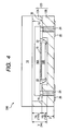
- a semiconductor package 300 shown in Fig. 4 has a structure in which a silicon substrate 12A having a cavity 14A to be a through hole formed and taking a shape of a window frame is stacked through a bonding surface 30 on another silicon substrate 12B having a cavity 14B to be a bottomed hole, and a silicon substrate stacked product 120 is thus formed.
- Corresponding members to the members shown in Fig. 1 have the same reference numerals as those in Fig. 1 . In the case in which a plurality of corresponding members is provided, alphabet is added to an end of the reference numeral for a distinction.
- a total height of the through cavity 14A having a height corresponding to a total thickness of the silicon substrate 12A and the bottomed cavity 14B of the silicon substrate 12B can be utilized as a height Y of the cavity 14 in the same manner as in the second embodiment.
- a maximum value of 675 ⁇ m in a thickness after polishing can be exactly utilized as a maximum value of a height YA of the cavity 14A for the silicon substrate 12A.
- ⁇ m obtained by subtracting a bottom thickness of 200 ⁇ m from 675 ⁇ m can be utilized as a maximum value of a height YB of the cavity 14B.
- An electronic device chip 16B of a different type or the same type is provided on an electronic device chip 16A through an adhesive layer 15, and both of the chips 16A and 16B are connected to each other through a wiring bonding 22 to form a stack.
- the stack is turned over to carry out a flip-chip bonding to an upper end of a through electrode 24 of the lower silicon substrate 12B via a bump 19 of the electronic device chip 16A. Consequently, the bump 19 of the electronic device chip 16B is led to a back wiring 26 for a connection to a mounting substrate.
- a semiconductor package 400 shown in Fig. 5 has such a structure that a silicon substrate 12A having a cavity 14A to be a bottomed hole is stacked on a silicon substrate 12B having a cavity 14B to be a through hole with a taper which is opened and taking a shape of a window frame through a back face of a bottom part of the silicon substrate 12A set to be a bonding surface 30, and a silicon substrate stacked product 120 is thus formed. More specifically, the bottom part of the cavity 12A is set to be a boundary region, and the cavities 12A and 12B are vertically opened respectively.
- Members corresponding to the members shown in Fig. 1 have the same reference numerals as those in Fig. 1 . In the case in which a plurality of corresponding members is provided, alphabet or alphabet and a figure is/are added to an end of the reference numeral for a distinction.
- the bottomed cavity 14A has a maximum height (475 ⁇ m) obtained by subtracting a thickness Z of the bottom part from a thickness (675 ⁇ m : 8-inch wafer, and so forth) after polishing of a wafer put on the market in the same as in the related-art structure shown in Fig. 1 .
- the through cavity 14B taking the shape of a window frame can be utilized by setting, as a maximum height, a total thickness (675 ⁇ m) after polishing of the wafer put on the market in the same manner as in the first embodiment of Fig. 2 and the third embodiment of Fig. 4 .
- An electronic device chip 16A2 is provided on a bottom face of the cavity 14A through an adhesive layer 15 in the upper cavity 14A, and an electronic device chip 16A1 of a different type or the same type is provided thereon through the adhesive layer 15 to form a stack.
- the electronic device chips 16A1 and 16A2 are connected to a wiring pattern 20A on the bottom face of the cavity 14A through wire bondings 22A1 and 22A2, respectively.
- the upper cavity 14A is sealed in airtightness by means of a cover 18 bonded to the silicon substrate 12A, and an inner part is substituted for an inert gas or is brought into a vacuum state.
- an electronic device chip 16B2 is provided through the adhesive layer 15 on a bottom face constituted by a back face of the silicon substrate 12A and an electronic device chip 16B1 of a different type or the same type is provided thereon through the adhesive layer 15 to form a stack.
- the electronic device chips 16A and 16B are connected to a wiring pattern 20B on a bottom face of the cavity 14B through wire bondings 22B1 and 22B2, respectively.
- An inner part of the lower cavity 14B is actually filled with a mold resin 28.
- the wiring pattern 20B is led to a back wiring 26 for a connection to a mounting substrate through a taper wiring 26T.
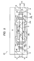
- a semiconductor package 500 shown in Fig. 6 has such a structure that a silicon substrate 12A having a cavity 14A to be a through hole and taking a shape of a window frame is stacked on a silicon substrate 12B having a cavity 14B to be a bottomed hole formed through a back face of a bottom part of the silicon substrate 12B set to be a bonding surface 30, and a silicon substrate stacked product 120 is thus formed. More specifically, the bottom part of the cavity 12B is set to be a boundary region, and the cavities 12A and 12B are vertically opened respectively.
- Members corresponding to the members shown in Fig. 1 have the same reference numerals as those in Fig. 1 . In the case in which a plurality of corresponding members is provided, alphabet or alphabet and a figure is/are added to an end of the reference numeral for a distinction.
- the through cavity 14A can be utilized by setting, as a maximum height, a total thickness (675 ⁇ m) after polishing of the wafer put on the market in the same manner as in the first embodiment and the third embodiment of Fig. 4 , and referring to the silicon substrate 12B, the bottomed cavity 14B has a maximum height (475 ⁇ m) obtained by subtracting a thickness Z of the bottom part from a thickness (675 ⁇ m : 8-inch wafer, and so forth) after polishing of a wafer put on the market in the same manner as in the related-art structure shown in Fig. 1 .
- An electronic device chip 16A2 is provided on a bottom face constituted by the back face of the silicon substrate 12B through an adhesive layer 15 in the upper cavity 14A, and an electronic device chip 16A1 of a different type or the same type is provided thereon through the adhesive layer 15 to form a stack.
- the electronic device chips 16A1 and 16A2 are connected to a wiring pattern 20A on the bottom face of the cavity 14A through wire bondings 22A1 and 22A2, respectively.
- the upper cavity 14A is sealed in airtightness by means of a cover 18 bonded to the silicon substrate 12A, and an inner part is substituted for an inert gas or is brought into a vacuum state.
- an electronic device chip 16B2 is provided through the adhesive layer 15 on a bottom face of the cavity 14B and an electronic device chip 16B1 of a different type or the same type is provided thereon through the adhesive layer 15 to form a stack.
- the electronic device chips 16B1 and 16B2 are connected to a wiring pattern 20B on a bottom face of the cavity 14B through wire bondings 22B1 and 22B2, respectively.
- An inner part of the lower cavity 14B is actually filled with a mold resin 28.
- the wiring pattern 20B is led to a back wiring 26 for a connection to a mounting substrate through a taper wiring 26T.
- the wiring pattern 20A in the upper cavity 14A and the wiring pattern 20B in the lower cavity 14B are connected to each other through a via 23 penetrating a bottom part of the lower silicon substrate 12B.
- a semiconductor package in which an electronic device chip is provided in a cavity of a silicon substrate beyond a limitation of a chip mounting height based on a standard thickness of a silicon substrate on the market.
Landscapes
- Engineering & Computer Science (AREA)
- Microelectronics & Electronic Packaging (AREA)
- Manufacturing & Machinery (AREA)
- Led Device Packages (AREA)
- Solid State Image Pick-Up Elements (AREA)
- Light Receiving Elements (AREA)
- Container, Conveyance, Adherence, Positioning, Of Wafer (AREA)
Applications Claiming Priority (1)
| Application Number | Priority Date | Filing Date | Title |
|---|---|---|---|
| JP2007288907A JP4912275B2 (ja) | 2007-11-06 | 2007-11-06 | 半導体パッケージ |
Publications (1)
| Publication Number | Publication Date |
|---|---|
| EP2058872A2 true EP2058872A2 (en) | 2009-05-13 |
Family
ID=40230534
Family Applications (1)
| Application Number | Title | Priority Date | Filing Date |
|---|---|---|---|
| EP08168216A Withdrawn EP2058872A2 (en) | 2007-11-06 | 2008-11-03 | Semiconductor package |
Country Status (4)
| Country | Link |
|---|---|
| US (1) | US7960820B2 (https=) |
| EP (1) | EP2058872A2 (https=) |
| JP (1) | JP4912275B2 (https=) |
| TW (1) | TW200921860A (https=) |
Cited By (1)
| Publication number | Priority date | Publication date | Assignee | Title |
|---|---|---|---|---|
| US20100320598A1 (en) * | 2009-06-18 | 2010-12-23 | Shinko Electric Industries Co., Ltd. | Semiconductor device and fabrication method thereof |
Families Citing this family (30)
| Publication number | Priority date | Publication date | Assignee | Title |
|---|---|---|---|---|
| KR100836663B1 (ko) * | 2006-02-16 | 2008-06-10 | 삼성전기주식회사 | 캐비티가 형성된 패키지 온 패키지 및 그 제조 방법 |
| DE102009022901A1 (de) * | 2009-05-27 | 2010-12-02 | Osram Opto Semiconductors Gmbh | Optoelektronisches Modul und Verfahren zur Herstellung eines optoelektronischen Moduls |
| JP5208871B2 (ja) * | 2009-07-13 | 2013-06-12 | 浜松ホトニクス株式会社 | 光検出器 |
| JP5100715B2 (ja) * | 2009-07-13 | 2012-12-19 | 株式会社東芝 | 半導体装置及び半導体装置の製造方法 |
| TWI453957B (zh) * | 2010-05-24 | 2014-09-21 | Advanced Optoelectronic Tech | 發光二極體之封裝結構 |
| TWI406435B (zh) * | 2010-08-06 | 2013-08-21 | Advanced Optoelectronic Tech | 發光二極體製造方法 |
| US9443834B2 (en) * | 2010-09-02 | 2016-09-13 | Micron Technology, Inc. | Back-to-back solid state lighting devices and associated methods |
| JP2012119601A (ja) * | 2010-12-03 | 2012-06-21 | Nec Corp | インターポーザ及び半導体装置 |
| US9013011B1 (en) * | 2011-03-11 | 2015-04-21 | Amkor Technology, Inc. | Stacked and staggered die MEMS package and method |
| US9105635B2 (en) * | 2013-03-13 | 2015-08-11 | Intel Corporation | Stubby pads for channel cross-talk reduction |
| JP6434494B2 (ja) * | 2014-03-10 | 2018-12-05 | 三菱重工業株式会社 | マルチチップモジュール、オンボードコンピュータ、センサインターフェース基板、及びマルチチップモジュール製造方法 |
| JP2016004888A (ja) * | 2014-06-17 | 2016-01-12 | イビデン株式会社 | プリント配線板及びプリント配線板の製造方法 |
| JP6663167B2 (ja) * | 2015-03-18 | 2020-03-11 | 浜松ホトニクス株式会社 | 光検出装置 |
| US11211305B2 (en) | 2016-04-01 | 2021-12-28 | Texas Instruments Incorporated | Apparatus and method to support thermal management of semiconductor-based components |
| US10861796B2 (en) * | 2016-05-10 | 2020-12-08 | Texas Instruments Incorporated | Floating die package |
| US10179730B2 (en) | 2016-12-08 | 2019-01-15 | Texas Instruments Incorporated | Electronic sensors with sensor die in package structure cavity |
| US10411150B2 (en) | 2016-12-30 | 2019-09-10 | Texas Instruments Incorporated | Optical isolation systems and circuits and photon detectors with extended lateral P-N junctions |
| US10074639B2 (en) | 2016-12-30 | 2018-09-11 | Texas Instruments Incorporated | Isolator integrated circuits with package structure cavity and fabrication methods |
| US9929110B1 (en) | 2016-12-30 | 2018-03-27 | Texas Instruments Incorporated | Integrated circuit wave device and method |
| US10121847B2 (en) | 2017-03-17 | 2018-11-06 | Texas Instruments Incorporated | Galvanic isolation device |
| JP6993220B2 (ja) * | 2017-12-26 | 2022-01-13 | 京セラ株式会社 | 電子部品収納用パッケージ、電子装置および電子モジュール |
| DE102018100946A1 (de) * | 2018-01-17 | 2019-07-18 | Osram Opto Semiconductors Gmbh | Bauteil und verfahren zur herstellung eines bauteils |
| KR102796767B1 (ko) * | 2019-07-10 | 2025-04-16 | 삼성전자주식회사 | 인터포저를 포함하는 전자 장치 |
| SG10201908828WA (en) | 2019-09-23 | 2021-04-29 | Apple Inc | Embedded Packaging Concepts for Integration of ASICs and Optical Components |
| US11942386B2 (en) * | 2020-08-24 | 2024-03-26 | Texas Instruments Incorporated | Electronic devices in semiconductor package cavities |
| JP2022186420A (ja) | 2021-06-04 | 2022-12-15 | キオクシア株式会社 | 半導体装置の製造方法および半導体装置 |
| WO2023276100A1 (ja) * | 2021-07-01 | 2023-01-05 | 三菱電機株式会社 | パワーモジュール |
| US12153268B2 (en) * | 2022-01-03 | 2024-11-26 | Apple Inc. | Technologies for increased volumetric and functional efficiencies of optical packages |
| JP7741745B2 (ja) * | 2022-02-15 | 2025-09-18 | キオクシア株式会社 | 半導体装置およびその製造方法 |
| US20240332105A1 (en) * | 2023-04-03 | 2024-10-03 | Nxp Usa, Inc. | Multidevice package with recessed mounting surface |
Citations (1)
| Publication number | Priority date | Publication date | Assignee | Title |
|---|---|---|---|---|
| JP2007208041A (ja) | 2006-02-02 | 2007-08-16 | Shinko Electric Ind Co Ltd | 半導体装置及び半導体装置の製造方法 |
Family Cites Families (9)
| Publication number | Priority date | Publication date | Assignee | Title |
|---|---|---|---|---|
| JPS5875859A (ja) * | 1981-10-30 | 1983-05-07 | Fujitsu Ltd | 半導体装置 |
| US5422435A (en) * | 1992-05-22 | 1995-06-06 | National Semiconductor Corporation | Stacked multi-chip modules and method of manufacturing |
| US6343019B1 (en) * | 1997-12-22 | 2002-01-29 | Micron Technology, Inc. | Apparatus and method of stacking die on a substrate |
| US20040038442A1 (en) * | 2002-08-26 | 2004-02-26 | Kinsman Larry D. | Optically interactive device packages and methods of assembly |
| JP2004296613A (ja) * | 2003-03-26 | 2004-10-21 | Renesas Technology Corp | 半導体装置 |
| JP2006186357A (ja) * | 2003-10-03 | 2006-07-13 | Matsushita Electric Works Ltd | センサ装置及びその製造方法 |
| JP4692260B2 (ja) * | 2005-12-12 | 2011-06-01 | 株式会社デンソー | 半導体力学量センサ装置およびその製造方法 |
| JP2007287967A (ja) * | 2006-04-18 | 2007-11-01 | Shinko Electric Ind Co Ltd | 電子部品装置 |
| JP4933934B2 (ja) * | 2007-03-28 | 2012-05-16 | ラピスセミコンダクタ株式会社 | 半導体装置及び半導体装置の製造方法 |
-
2007
- 2007-11-06 JP JP2007288907A patent/JP4912275B2/ja not_active Expired - Fee Related
-
2008
- 2008-11-03 EP EP08168216A patent/EP2058872A2/en not_active Withdrawn
- 2008-11-05 TW TW097142608A patent/TW200921860A/zh unknown
- 2008-11-05 US US12/265,203 patent/US7960820B2/en active Active
Patent Citations (1)
| Publication number | Priority date | Publication date | Assignee | Title |
|---|---|---|---|---|
| JP2007208041A (ja) | 2006-02-02 | 2007-08-16 | Shinko Electric Ind Co Ltd | 半導体装置及び半導体装置の製造方法 |
Cited By (1)
| Publication number | Priority date | Publication date | Assignee | Title |
|---|---|---|---|---|
| US20100320598A1 (en) * | 2009-06-18 | 2010-12-23 | Shinko Electric Industries Co., Ltd. | Semiconductor device and fabrication method thereof |
Also Published As
| Publication number | Publication date |
|---|---|
| JP4912275B2 (ja) | 2012-04-11 |
| TW200921860A (en) | 2009-05-16 |
| US7960820B2 (en) | 2011-06-14 |
| JP2009117611A (ja) | 2009-05-28 |
| US20090115049A1 (en) | 2009-05-07 |
Similar Documents
| Publication | Publication Date | Title |
|---|---|---|
| EP2058872A2 (en) | Semiconductor package | |
| US8198108B2 (en) | Semiconductor device and method for manufacturing the same | |
| KR101720441B1 (ko) | 박형 기판 PoP 구조 | |
| US8017435B2 (en) | Method for packaging electronic devices and integrated circuits | |
| US20160291269A1 (en) | Photonic integrated circuit chip packaging | |
| KR100682970B1 (ko) | 고체 촬상 장치 및 그 제조 방법 | |
| JP4832782B2 (ja) | 段差型ダイを有する半導体パッケージとその製造方法 | |
| US11031356B2 (en) | Semiconductor package structure for improving die warpage and manufacturing method thereof | |
| US20070166867A1 (en) | Integrated circuit package system with image sensor system | |
| TWI699012B (zh) | 發光晶片封裝結構及封裝方法 | |
| EP3104410B1 (en) | Multi-chip module, on-board computer, sensor interface substrate, and multi-chip module manufacturing method | |
| CN107546194B (zh) | 用于具有玻璃顶盖的混合式光学封装的结构和方法 | |
| US20180366393A1 (en) | Chip packaging method and package structure | |
| US8546190B2 (en) | Method for positioning chips during the production of a reconstituted wafer | |
| US8198689B2 (en) | Package structure having micro-electromechanical element and fabrication method thereof | |
| CN100448003C (zh) | 半导体器件 | |
| KR20220127838A (ko) | 집적 반도체 웨이퍼 디바이스를 위한 장착 방법 및 장착 디바이스 | |
| US20050253208A1 (en) | Semiconductor micro device | |
| CN115149394B (zh) | 一种光电器件集成封装结构及其制造方法 | |
| KR20010061886A (ko) | 적층 칩 패키지 | |
| CN104752491A (zh) | 用于半导体装置的间隔体层和半导体装置 | |
| CN112289689A (zh) | 半导体封装结构制作方法和半导体封装结构 | |
| KR100566780B1 (ko) | 적층형 멀티 칩 패키지 제조 방법 및 이를 이용한 적층형 멀티 칩 패키지 | |
| US20220181223A1 (en) | Covers for semiconductor package components | |
| JPS6223185A (ja) | ハイブリッド光ic装置およびその製造方法 |
Legal Events
| Date | Code | Title | Description |
|---|---|---|---|
| PUAI | Public reference made under article 153(3) epc to a published international application that has entered the european phase |
Free format text: ORIGINAL CODE: 0009012 |
|
| AK | Designated contracting states |
Kind code of ref document: A2 Designated state(s): AT BE BG CH CY CZ DE DK EE ES FI FR GB GR HR HU IE IS IT LI LT LU LV MC MT NL NO PL PT RO SE SI SK TR |
|
| AX | Request for extension of the european patent |
Extension state: AL BA MK RS |
|
| STAA | Information on the status of an ep patent application or granted ep patent |
Free format text: STATUS: THE APPLICATION IS DEEMED TO BE WITHDRAWN |
|
| 18D | Application deemed to be withdrawn |
Effective date: 20130601 |