EP2058664A2 - Appareil et procédé de manipulation de fluides pour analyse - Google Patents
Appareil et procédé de manipulation de fluides pour analyse Download PDFInfo
- Publication number
- EP2058664A2 EP2058664A2 EP20090152512 EP09152512A EP2058664A2 EP 2058664 A2 EP2058664 A2 EP 2058664A2 EP 20090152512 EP20090152512 EP 20090152512 EP 09152512 A EP09152512 A EP 09152512A EP 2058664 A2 EP2058664 A2 EP 2058664A2
- Authority
- EP
- European Patent Office
- Prior art keywords
- fluid
- vessels
- reaction vessel
- vessel
- supported
- Prior art date
- Legal status (The legal status is an assumption and is not a legal conclusion. Google has not performed a legal analysis and makes no representation as to the accuracy of the status listed.)
- Granted
Links
Images


Classifications
-
- G—PHYSICS
- G01—MEASURING; TESTING
- G01N—INVESTIGATING OR ANALYSING MATERIALS BY DETERMINING THEIR CHEMICAL OR PHYSICAL PROPERTIES
- G01N35/00—Automatic analysis not limited to methods or materials provided for in any single one of groups G01N1/00 - G01N33/00; Handling materials therefor
- G01N35/10—Devices for transferring samples or any liquids to, in, or from, the analysis apparatus, e.g. suction devices, injection devices
- G01N35/1004—Cleaning sample transfer devices
-
- B—PERFORMING OPERATIONS; TRANSPORTING
- B01—PHYSICAL OR CHEMICAL PROCESSES OR APPARATUS IN GENERAL
- B01L—CHEMICAL OR PHYSICAL LABORATORY APPARATUS FOR GENERAL USE
- B01L13/00—Cleaning or rinsing apparatus
- B01L13/02—Cleaning or rinsing apparatus for receptacle or instruments
-
- B—PERFORMING OPERATIONS; TRANSPORTING
- B01—PHYSICAL OR CHEMICAL PROCESSES OR APPARATUS IN GENERAL
- B01L—CHEMICAL OR PHYSICAL LABORATORY APPARATUS FOR GENERAL USE
- B01L3/00—Containers or dishes for laboratory use, e.g. laboratory glassware; Droppers
- B01L3/50—Containers for the purpose of retaining a material to be analysed, e.g. test tubes
- B01L3/502—Containers for the purpose of retaining a material to be analysed, e.g. test tubes with fluid transport, e.g. in multi-compartment structures
- B01L3/5025—Containers for the purpose of retaining a material to be analysed, e.g. test tubes with fluid transport, e.g. in multi-compartment structures for parallel transport of multiple samples
- B01L3/50255—Multi-well filtration
-
- G—PHYSICS
- G01—MEASURING; TESTING
- G01N—INVESTIGATING OR ANALYSING MATERIALS BY DETERMINING THEIR CHEMICAL OR PHYSICAL PROPERTIES
- G01N35/00—Automatic analysis not limited to methods or materials provided for in any single one of groups G01N1/00 - G01N33/00; Handling materials therefor
- G01N35/0098—Automatic analysis not limited to methods or materials provided for in any single one of groups G01N1/00 - G01N33/00; Handling materials therefor involving analyte bound to insoluble magnetic carrier, e.g. using magnetic separation
-
- G—PHYSICS
- G01—MEASURING; TESTING
- G01N—INVESTIGATING OR ANALYSING MATERIALS BY DETERMINING THEIR CHEMICAL OR PHYSICAL PROPERTIES
- G01N35/00—Automatic analysis not limited to methods or materials provided for in any single one of groups G01N1/00 - G01N33/00; Handling materials therefor
- G01N35/10—Devices for transferring samples or any liquids to, in, or from, the analysis apparatus, e.g. suction devices, injection devices
- G01N35/1065—Multiple transfer devices
-
- B—PERFORMING OPERATIONS; TRANSPORTING
- B01—PHYSICAL OR CHEMICAL PROCESSES OR APPARATUS IN GENERAL
- B01L—CHEMICAL OR PHYSICAL LABORATORY APPARATUS FOR GENERAL USE
- B01L2200/00—Solutions for specific problems relating to chemical or physical laboratory apparatus
- B01L2200/06—Fluid handling related problems
- B01L2200/0647—Handling flowable solids, e.g. microscopic beads, cells, particles
- B01L2200/0668—Trapping microscopic beads
-
- B—PERFORMING OPERATIONS; TRANSPORTING
- B01—PHYSICAL OR CHEMICAL PROCESSES OR APPARATUS IN GENERAL
- B01L—CHEMICAL OR PHYSICAL LABORATORY APPARATUS FOR GENERAL USE
- B01L2400/00—Moving or stopping fluids
- B01L2400/04—Moving fluids with specific forces or mechanical means
- B01L2400/0475—Moving fluids with specific forces or mechanical means specific mechanical means and fluid pressure
- B01L2400/0487—Moving fluids with specific forces or mechanical means specific mechanical means and fluid pressure fluid pressure, pneumatics
- B01L2400/049—Moving fluids with specific forces or mechanical means specific mechanical means and fluid pressure fluid pressure, pneumatics vacuum
-
- B—PERFORMING OPERATIONS; TRANSPORTING
- B01—PHYSICAL OR CHEMICAL PROCESSES OR APPARATUS IN GENERAL
- B01L—CHEMICAL OR PHYSICAL LABORATORY APPARATUS FOR GENERAL USE
- B01L2400/00—Moving or stopping fluids
- B01L2400/06—Valves, specific forms thereof
- B01L2400/0633—Valves, specific forms thereof with moving parts
- B01L2400/0655—Valves, specific forms thereof with moving parts pinch valves
-
- B—PERFORMING OPERATIONS; TRANSPORTING
- B01—PHYSICAL OR CHEMICAL PROCESSES OR APPARATUS IN GENERAL
- B01L—CHEMICAL OR PHYSICAL LABORATORY APPARATUS FOR GENERAL USE
- B01L2400/00—Moving or stopping fluids
- B01L2400/06—Valves, specific forms thereof
- B01L2400/0688—Valves, specific forms thereof surface tension valves, capillary stop, capillary break
-
- B—PERFORMING OPERATIONS; TRANSPORTING
- B01—PHYSICAL OR CHEMICAL PROCESSES OR APPARATUS IN GENERAL
- B01L—CHEMICAL OR PHYSICAL LABORATORY APPARATUS FOR GENERAL USE
- B01L3/00—Containers or dishes for laboratory use, e.g. laboratory glassware; Droppers
- B01L3/50—Containers for the purpose of retaining a material to be analysed, e.g. test tubes
- B01L3/508—Containers for the purpose of retaining a material to be analysed, e.g. test tubes rigid containers not provided for above
- B01L3/5082—Test tubes per se
-
- Y—GENERAL TAGGING OF NEW TECHNOLOGICAL DEVELOPMENTS; GENERAL TAGGING OF CROSS-SECTIONAL TECHNOLOGIES SPANNING OVER SEVERAL SECTIONS OF THE IPC; TECHNICAL SUBJECTS COVERED BY FORMER USPC CROSS-REFERENCE ART COLLECTIONS [XRACs] AND DIGESTS
- Y10—TECHNICAL SUBJECTS COVERED BY FORMER USPC
- Y10T—TECHNICAL SUBJECTS COVERED BY FORMER US CLASSIFICATION
- Y10T137/00—Fluid handling
- Y10T137/0318—Processes
- Y10T137/0391—Affecting flow by the addition of material or energy
-
- Y—GENERAL TAGGING OF NEW TECHNOLOGICAL DEVELOPMENTS; GENERAL TAGGING OF CROSS-SECTIONAL TECHNOLOGIES SPANNING OVER SEVERAL SECTIONS OF THE IPC; TECHNICAL SUBJECTS COVERED BY FORMER USPC CROSS-REFERENCE ART COLLECTIONS [XRACs] AND DIGESTS
- Y10—TECHNICAL SUBJECTS COVERED BY FORMER USPC
- Y10T—TECHNICAL SUBJECTS COVERED BY FORMER US CLASSIFICATION
- Y10T137/00—Fluid handling
- Y10T137/0318—Processes
- Y10T137/0396—Involving pressure control
-
- Y—GENERAL TAGGING OF NEW TECHNOLOGICAL DEVELOPMENTS; GENERAL TAGGING OF CROSS-SECTIONAL TECHNOLOGIES SPANNING OVER SEVERAL SECTIONS OF THE IPC; TECHNICAL SUBJECTS COVERED BY FORMER USPC CROSS-REFERENCE ART COLLECTIONS [XRACs] AND DIGESTS
- Y10—TECHNICAL SUBJECTS COVERED BY FORMER USPC
- Y10T—TECHNICAL SUBJECTS COVERED BY FORMER US CLASSIFICATION
- Y10T436/00—Chemistry: analytical and immunological testing
- Y10T436/25—Chemistry: analytical and immunological testing including sample preparation
- Y10T436/25375—Liberation or purification of sample or separation of material from a sample [e.g., filtering, centrifuging, etc.]
-
- Y—GENERAL TAGGING OF NEW TECHNOLOGICAL DEVELOPMENTS; GENERAL TAGGING OF CROSS-SECTIONAL TECHNOLOGIES SPANNING OVER SEVERAL SECTIONS OF THE IPC; TECHNICAL SUBJECTS COVERED BY FORMER USPC CROSS-REFERENCE ART COLLECTIONS [XRACs] AND DIGESTS
- Y10—TECHNICAL SUBJECTS COVERED BY FORMER USPC
- Y10T—TECHNICAL SUBJECTS COVERED BY FORMER US CLASSIFICATION
- Y10T436/00—Chemistry: analytical and immunological testing
- Y10T436/25—Chemistry: analytical and immunological testing including sample preparation
- Y10T436/2575—Volumetric liquid transfer
Definitions
- the present invention is directed toward testing of specimens, and particularly toward an apparatus and method for processing specimens during testing, including adding fluids such as reagents during the processing of specimens.
- Testing sample biological specimens is commonly done, for example, to check for the presence of an item of interest, which item may be or include all or portions of a specific region of DNA, RNA, or fragments thereof, complements, peptides, polypeptides, enzymes, prisons, proteins, messenger RNA, transfer RNA, mitochondrial RNA or DNA, antibodies, antigens, allergens, parts of biological entities such as cells, virons or the like, surface proteins, or functional equivalents of the above, etc.
- Specimens such as a patient's body fluids (e.g., serum, whole blood; urine, swabs, plasma, cerebral-spinal fluid, lymph fluids, tissue solids) can be analyzed using a number of different tests to provide information about a patient's health.
- body fluids e.g., serum, whole blood; urine, swabs, plasma, cerebral-spinal fluid, lymph fluids, tissue solids
- Such testing is accomplished using automated devices which handle multiple specimens and fluids (typically, reagents).
- automated devices typically will use sets of pipettes to move various fluids between their original containers (usually receptacles such as open topped tubes) and containers in which the specimens are to be processed.
- a set of 8 specimens may be contained in 8 tubes or other receptacles loaded in a rack on the device, and a head carrying 8 pipettes will, through programmed motion, move the pipettes into those 8 tubes, where a vacuum will be applied to extract a selected amount of each specimen from its tube into the pipettes.
- the head will then retract the pipettes from the tubes and move to another set of tubes located at a processing station, depositing the extracted amounts of each specimen from the pipettes into sets of testing tubes.
- racks or trays of multiple tubes are usually moved from one station to the next for different stages of processing.
- a heating element may be provided at one station, and a magnetic element introducing a magnetic field in the tubes may be provided at another station.
- multiple trays of multiple tubes may be actively processed in series and simultaneously at different stations.
- processing can result in resource contention, where one rack of tubes is delayed from being placed at a station while another rack of tubes completes its processing at that station when, as is commonly the case, the processing time at one station is different than the processing time at another station.
- a tray of tubes which have completed processing at one station may be delayed from being processed at the next station until another tray of tubes at that next station has completed its processing there.
- a slow overall processing time can reduce the amount of tests which are performed during a given day, and thereby either delay the completion of tests or require significant additional investment of capital for additional devices to allow for a desired testing capacity level.
- the specimens are variously handled according to the purpose of the testing (e.g., incubated, prepared, lysed, eluted, etc.).
- the specimens may be prepared for analyzing, as for example by separating DNA or RNA from the specimen.
- the specimens may also or alternatively be analyzed.
- processes involve the addition of various fluids (typically reagents) to the specimen in each tube.
- a reagent may be added to each of the tubes to wash the specimens, and second and third (and more) reagents may be added to the specimens in the course of carrying out other processes to, for example, unbind and/or separate the DNA or RNA of interest so that it may be extracted from the specimen in each tube for subsequent testing. Similar processes, in which the same or different reagents are added to and/or extracted from the tubes, may also occur after the specimen has been prepared as part of analyzing the prepared specimens.
- magnetic fields have been used to assist in separating analytes of interest from the fluid in the tubes.
- analytes of interest have been bound to magnetic particles within a reagent and a magnetic field applied to pull the particles and bound analyte to one side of the tube, whereby the reagent may be drawn out of the tube to leave a concentration of the analyte therein.
- the tubes have been moved in order to accomplish the desired orientation of the magnetic field in the tubes.
- the handling of the reagents and other fluids with automated devices such as described above can be problematic.
- the reagents may be automatically moved from receptacles to the specimen containing tubes in the processing station by use of the head and pipettes such as noted, it is in the first instance necessary to load the appropriate reagent into the appropriate receptacle on the device in order to ensure that the head and pipettes are adding the appropriate reagent to the appropriate specimen containing tube at the appropriate time in the process.
- loading the appropriate reagent into the appropriate receptacle has been accomplished in several different ways.
- the individual who is controlling the device manually measures and adds the reagents to receptacles, and then places those receptacles on the device.
- the loading of reagents is automatically accomplished by the device itself, which uses some transfer apparatus (such as a head and pipette(s) as previously described) to move the reagents from bulk supplies of the reagents provided with the device.
- Removing reagents from tubes is similarly accomplished, such as by use of a head which positions pipettes in the tube and vacuum draws the fluid from the tubes into the pipettes.
- a head which positions pipettes in the tube and vacuum draws the fluid from the tubes into the pipettes.
- Such a process can be time consuming, and tie up the head from other uses, particularly if prevention of contamination between tubes makes it necessary to use a new pipette with each tube.
- it may be necessary to repetitively move the head to discharge, discard and pick up new pipettes every time fluid is drawn from tubes e.g., a head carrying eight pipettes may have to be cycled six times when used with a tray of 48 tubes, where each cycle requires discharging and discarding used pipettes, and picking up new pipettes).
- U.S. Patent No. 6,117,398 alternatively discloses drawing fluid from the bottom of a sample vessel, wherein a valve is situated between every sample processing vessel and the waste container.
- the present invention is directed to overcoming one or more of the problems as set forth above.
- a reaction vessel for testing an analyte in a fluid has an open top and a drain opening in its bottom, with the drain opening being adapted to support a selected head of fluid and to drain fluid therethrough when a selected pressure differential exists between the top of the fluid and the bottom of the vessel.
- the surface tension of the fluid supports the selected head of fluid when the pressure differential between the top of the fluid and the bottom of the vessel is less than the selected pressure differential.
- a hydrophobic frit is associated with the drain opening.
- the drain opening permits draining of the fluid only when the relative pressure between the top of the fluid and the drain opening is at least a selected amount.
- a non-wettable surface is provided around the drain opening on the outside of the vessel.
- a drain opening protrusion extends beyond the bottom surface of the vessel.
- a processing zone for a specimen handling device including a support for a plurality of reaction vessels having drain openings in their bottoms, passages adapted to communicate with the bottom drain openings of supported reaction vessels, and a source of air at non-atmospheric pressure adapted to selectively drain fluid through the drain openings in supported reaction vessels.
- the drain openings are adapted to support a selected head of fluid in the vessels.
- the source of air at non-atmospheric pressure is a vacuum source for drawing a vacuum in the passages.
- a heater is provided for heating reaction vessels supported in the processing zone.
- reaction vessels are adapted to selectively contain fluids having a surface tension sufficient to support a selected head of fluid without the fluid draining through the drain openings, and the source of air at non-atmospheric pressure is adapted to selectively create a relatively lower pressure at the drain opening than at the top of the fluid to overcome the fluid surface tension and selectively drain the fluid through the drain openings.
- the support is adapted to support the plurality of reaction vessels in at least two rows, each row having a defined space from at least one adjacent row.
- the defined space between rows is a generally vertical longitudinal slot
- a bar magnet extends generally horizontally and is supported for selected vertical movement in the slot.
- the support is adapted to support the plurality of reaction vessels in at least four rows and the defined space is a generally vertical longitudinal first slot between the first and second rows and a generally vertical longitudinal second slot between the third and fourth rows, with the bar magnet being a first bar magnet supported for selected vertical movement in the first slot and a second bar magnet supported for selected vertical movement in the second slot.
- the first and second bar magnets are supported for vertical movement together.
- a method of processing analytes in fluids in reaction vessels including the steps of (1) supporting a reaction vessel containing an analyte in a fluid, the reaction vessel having a drain opening in its bottom capable of supporting a selected head of the fluid in the vessel by the surface tension of the fluid, (2) drawing the analyte to a side of the vessel to concentrate the analyte clear of the drain opening, and (3) selectively creating a pressure differential between the top of the fluid and the bottom of the drain opening sufficient to overcome the fluid surface tension and drain the fluid through the drain opening.
- the selectively creating a pressure differential step includes selectively creating a vacuum beneath the drain opening.
- the drawing step includes binding the analyte to a magnetic particle, and introducing a magnetic field into the vessel which draws the magnetic particle and bound analyte to the side of the vessel.
- the magnetic field is moved vertically along the height of the reaction vessel to draw the magnetic particles and bound analyte together into a pellet in the reaction vessel.
- the moving step moves the magnetic field down from an upper position near the top of the fluid in the reaction vessel to a position near the bottom of the reaction vessel whereby the pellet is formed near a bottom side of the reaction vessel.
- a processing zone for a specimen handling device including a support adapted to support a reaction vessel in a generally vertical orientation, and a magnet supported for selected vertical movement along one side of a supported reaction vessel.
- the support is adapted to support a plurality of reaction vessels in at least two rows where each row has a defined spacing from at least one adjacent row, and the magnet extends generally horizontally and is supported for selected vertical movement in the defined spacing.
- the defined spacing between rows comprises a generally vertical longitudinal slot, and magnet is a bar magnet or an electromagnet.
- the support is adapted to support the plurality of reaction vessels in generally parallel first, second, third and fourth rows
- the defined space is a generally vertical longitudinal first slot between the first and second rows and a generally vertical longitudinal second slot between the third and fourth rows
- the bar magnet includes a first bar magnet supported for selected vertical movement in the first slot and a second bar magnet supported for selected vertical movement in the second slot.
- the first and second bar magnets are supported for vertical movement together.
- a method of processing analytes in fluids in reaction vessels including the steps of (1) supporting a reaction vessel containing an analyte in a fluid, (2) binding the analyte to a magnetic particle, (3) introducing a magnetic field into the vessel which draws the magnetic particle and bound analyte to the side of the vessel, and (4) moving the magnetic field vertically along the height of the reaction vessel to draw the magnetic particle and bound analyte together into a pellet in the reaction vessel.
- the moving step moves the magnetic field down from an upper position near the top of the fluid in the reaction vessel to a position near the bottom of the reaction vessel whereby the pellet is formed near a bottom side of the reaction vessel.
- a fluid handling mechanism for an analyte testing device which includes a deck with a processing zone having a plurality of reaction vessels supported therein with upwardly facing openings.
- the fluid handling mechanism includes a first bulk supply of a first fluid, and a dispensing head having X discharge openings selectively positionable with each of the discharge openings over the upwardly facing openings of X selected reaction vessels, wherein X is at least four.
- a metering pump mechanism is adapted to selectively meter X units of a selected quantity of fluid from the first bulk supply, and selectively pump X units of metered selected quantities of fluid through the discharge openings to the selected reaction vessels.
- the deck supports a plurality of reaction vessels in a repeating pattern, each pattern including X reaction vessels, and the dispensing head discharge openings are arranged in the pattern.
- the repeating pattern comprises a plurality of rows of reaction vessels.
- the rows include at least eight reaction vessels, and X is at least eight.
- a second bulk supply of a second fluid is provided, and the metering pump mechanism is adapted to selectively meter the X units of the selected quantity of fluid from a selected one of the first and second bulk supplies.
- the metering pump mechanism includes X piston pumps, and X valve structures are also provided, where each valve structure is associated with one of the piston pumps and selectively switchable between providing a connection to (1) a selected one of the first and second bulk supplies, and (2) an associated discharge opening.
- Fig. 1 Two processing zones 20, 22 in accordance with the present invention and usable with a suitable automated testing device (not shown) are illustrated in Fig. 1 .
- the overall testing device is not (and need not be) shown in the figures.
- a suitable automatic testing device may be adapted for the substantial isolation of nucleic acids from biological samples, including the isolation and testing of nucleic acids from biological samples.
- a hood may be provided to protect against contamination from the environment in which the zones 20, 22 are located to prevent outside contaminants from entering therein as is known in the art.
- Such an automatic testing device may advantageously also include one or more of the following features: (1) a receptacle to hold and segregate from samples and reagents used pipette tips such that contamination from used tips is minimized, (2) aerosol control devices, for example without limitation, (a) a sample tube or reagent tube sealer, (b) electrodes for treating surfaces and/or liquids with electrical current capable of modifying nucleic acids, (c) an ultraviolet light source capable of degrading or modifying nucleic acids, (d) an apparatus for causing laminar air flow in or around the automatic testing device, and (3) an optical detector (e.g., a flourometer) for measuring the light absorbance or fluorescence of processed samples.
- an optical detector e.g., a flourometer
- Tecan AG manufactures a general purpose laboratory pipetting instrument with which the various described aspects of the invention may be used.
- many features of such instruments though usable with the present invention, do not form a part of the invention, and therefore are not shown in the figures.
- Those skilled in the art who obtain an understanding of the present invention will recognize such features, such as disclosed in, for example, in U.S. Serial No. 10/360,956 titled “Apparatus and Method for Handling Fluids for Analysis", filed February 7,2003, U.S. Patent No. 6,413,780 , titled “Structure and Method for Performing a Determination of an Item of Interest in a Sample", and U.S. Publication No. 2002-0127727 also titled “Structure and Method for Performing a Determination of an Item of Interest in a Sample", the complete disclosures of which are hereby incorporated by reference.
- a plurality of processing zones may be used with a single testing device such as shown, including not only multiple processing zones 20, 22 embodying aspects of the present invention such as shown in Fig. 1 , but also additional processing zones (not shown) for different types of processing or specimen handling.
- additional handling zones can be provided wherein reaction vessels may be prepared prior to desired processing by adding specimens, etc.
- the multiple processing zones 20, 22 illustrated in Fig. 1 assist in minimizing resource contention (i.e., conflicts arising where processing using one group of reaction vessels may be delayed until another group of reaction vessels has completed processing at the next required processing zone 20.
- Fig. 1 generally illustrates a processing zone 20 at which testing of specimen samples may be done.
- reaction vessels 26 (only one of which is shown in Fig. 1 ) containing specimens for testing may be loaded onto supports 30, 32 at each zone 20, 22.
- the supports 30, 32 may be support brackets or racks, for example, defining rows in which reaction vessels 26 may be supported, each with an upwardly open top.
- the supports 30, 32 may serve as heat shields to protect a user from heat blocks therebeneath (as described below).
- Suitable movable carriers may also be used which are transportable to and from the processing zones 20, 22 ( e.g., manually or by a suitable robotic arm) to facilitate handling reaction vessels where desired.
- the supports 30, 32 illustrated in Fig. 1 will support reaction vessels 26 in a repeating pattern, with a pattern consisting of a row of eight reaction vessels 26 repeated six times, whereby a total of forty-eight reaction vessels 26 may be processed simultaneously at one processing zone 20 or 22.
- the processing may be to isolate analytes of interest from up to forty-eight specimens (e.g., DNA or RNA), after which processing the isolated analyte may be further tested according to an appropriate protocol.
- forty-eight specimens e.g., DNA or RNA
- the present invention is not limited in any way to such processing, and could as readily be used with a device in which different processing or protocols are carried out.
- each of the processing zones 20, 22 includes heat blocks 40 which may be suitably controlled to heat the reaction vessels 26 to whatever temperatures, for whatever periods of time, is required by the processing or protocol being carried out.
- the heat blocks 40 may be configured so as to surround the reaction vessels 26 to dissipate heat from a suitable heater 42 evenly throughout the reaction vessels 26 in the processing zone 20, 22.
- the heat blocks 40 may also be arranged with a longitudinal, vertical slot between adjacent rows of reaction vessels 26.
- a longitudinal, vertical slot between adjacent rows of reaction vessels 26.
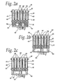
- suitable bar magnets 60, 62, 64 may be supported for movement in the slots 46, 48, 50 between the rows of reaction vessels 26.
- the bar magnets 60, 62, 64 are suitably supported for selected vertical movement together in the slots 46, 48, 50, as by a controlled drive 68 which moves a cross-support 70 on vertical guide rods 72.
- a controlled drive 68 which moves a cross-support 70 on vertical guide rods 72.
- any structure which would suitably control vertical movement of the bar magnets 60, 62, 64 as described hereafter so as to move the magnetic field 76 (see Fig. 2a ) in the reaction vessels 26.
- the analyte of interest dispersed in the reaction vessel 26 may be suitably bound to a magnetic material or particles in a suitable manner such as is known in the art.
- the magnets 60, 62, 64 may be selectively moved vertically in the slots 46, 48, 50 to draw the magnetic particles (and bound analyte of interest) to one side of the vessels 26. Morever, by selectively moving the magnets 60, 62, 64 along the side of the vessels 26 in the slots, the magnetic particles and bound analyte of interest within the reaction vessel 26 may be strongly drawn to the side of the vessels 26 throughout the height of the vessel 26 by essentially subjecting the vessel contents to a uniform magnetic force throughout its height.
- magnetic particles and bound analyte of interest may not only be drawn to the side of the vessels 26 but may also then be pulled down along the side of the vessels 26 as the magnets 60, 62, 64 move down whereby a desired pellet of such materials is formed at the bottom corner of the vessels 26.
- aspects of the present invention could also include the use of a magnet as described with a single reaction vessel 26, that is, moving a magnet along one side of one vessel 26 to draw the magnetic particles and bound analyte of interest to the side of the vessel 26 and down to form a pellet at a bottom corner of the vessel 26.
- each processing zone 20, 22 may include concave recesses 78 (see Fig. 3b ) for receiving the bottoms of the reaction vessels 26, for example, in the heat blocks 40.
- a horizontal drain passageway or channel 80 may extend along the length of the heat blocks 40 beneath each row of vessels 26, with a vertical passageway 82 connecting the horizontal passageway 80.
- a suitable vacuum source (indicated schematically at 86 in Fig. 3a ) may be applied to the passageways 80, 82 to selectively draw/drain fluid from the vessels 26 as described below.
- vacuum source 86 While a vacuum source 86 is described herein, it should be understood that the significant feature is a lower pressure beneath discharge or drain openings in the bottom of the vessels 26 (as described in detail below) relative to the pressure on the fluid at the top of the vessels 26. Therefore, it should be understood that this aspect of the invention could also be accomplished through the application, for example, of high pressure to the top of the reaction vessels 26 where the passageways 80, 82 are at atmospheric pressure, or a combination of pressure and vacuum.
- a reaction vessel 26 may be provided with a fluid 90 and sample having a depth (or height or head) H.
- a discharge or drain opening 92 is provided in the bottom of the reaction vessel 26, where the drain opening 92 is configured so that the surface tension of the fluid 90 in its condition at the processing zone 20, 22 is sufficient to support the height of fluid without the fluid draining through the drain opening 92. It should be understood that, while a single opening 92 is shown in Fig. 4a , it would advantageously be within the scope of the present invention to define the drain opening via multiple openings through the bottom of the vessel 26.
- Fig. 4b illustrates a reaction vessel 26 with one configuration of drain opening 92, where fluid 90 has passed through the drain opening 92 so as to form a bead 94 around the opening 92. So long as the opening 92 is small enough to maintain a bead 94 which is no greater in size than the surface tension of the fluid 90 can maintain, the fluid 90 will be supported in the vessel 26 (that is, until an additional force, a relative pressure between the top and bottom of the fluid 90, is selectively created by the introduction of a vacuum in the passageways 80, 82 beneath the vessels 26).
- Fig. 4c discloses an alternative embodiment of a reaction vessel 26a, wherein a suitable non-wettable coating or surface 96 is provided around the drain opening 92a. Such a non-wettable coating 96 will prevent a bead from spreading out onto the coating ( FIG. 4b illustrates a bead 94 which spreads out onto the outer surface of the vessel 26), such that a larger size drain opening 92a may be used while still maintaining the ability of the surface tension of the fluid 90 to support a desired height of fluid 90 in the vessel 26a.
- Fig. 4d discloses still another embodiment of a reaction vessel 26b, wherein a protruding tube or flange 98 is provided around the drain opening 92b.
- the flange 98 may also prevent the bead from spreading out to an area much larger than the flange 98, thereby allowing use of a larger drain opening 92b while still maintaining the ability of the surface tension of the fluid 90 to support the fluid 90 as described for Fig. 4c .
- Fig. 4e discloses yet another embodiment of a reaction vessel 26c, in which a hydrophobic frit 99 or other suitable hydrophobic porous material (such as may be obtained from Porex Corporation of Fairburn, Georgia) is associated with the vessel 26c to define the drain opening 92c.
- the hydrophobic frit 99 may be advantageously selected, based on the fluid, whereby the frit 99 will support the desired height of fluid 90 in vessel 26c, and will allow the fluid to pass therethrough when a selected pressure differential is introduced between the top of the vessel 26c and beneath the frit 99/drain opening 92c.
- a fluid having low surface tension properties e.g., alcohol
- the porosity of the frit material may advantageously be less than the material used with fluids having higher surface tension properties to enable the desired height of fluid to be supported as desired.
- vessels 26, 26a, 26b, 26c are particularly advantageous inasmuch as such vessels are low cost disposables.
- aspects of the present invention encompass still further vessels having drain openings which will support a head of fluid 90 by other than the fluid surface tension, while allowing that fluid to be selectively drained from the vessel responsive to a selected pressure differential created (e.g., by the introduction of a vacuum in the passageways 80, 82 beneath the vessels 26).
- a drain opening consisting of not only an opening in the vessel 26 but also a suitable passive valve may be provided to provide the desired fluid flow, where the passive valve is biased to block fluid flow unless a selected pressure differential across the valve is created.
- Fig. 4f illustrates a reaction vessel 26d having a duckbill valve 100 as one example of a suitable valve which would be pulled open by a selected pressure differential resulting from a vacuum in the passageways 80, 82.
- Those skilled in the art will recognize that many other valve structures providing such operation would be suitable, including, for example, umbrella valves, flapper valves and spring biased ball check valves, and could also be advantageously used with certain aspects of the present invention.
- Fig. 4g illustrates a reaction vessel 26e with a suitable connection 102 to passageways 80', 82' with a suitable pinch valve 104 and suitable control 106 for selectively closing and opening the passageway 80' as desired for operation.
- a hydrophobic frit 99' may also be provided in the bottom opening of the vessel 26e.
- Active valves may advantageously be selected which will support the desired height of fluid and may be opened to allow fluid to drain from the vessel 26e without assist by a pressure differential. However, it would be within the scope of certain aspects of the present invention to additionally provide a vacuum to assist in such draining when the active valves 104 are open.
- Valves such as described above may be a part of the reaction vessel, or part of the vacuum passageways 80, 82 beneath the vessel.
- Fig. 5 illustrates a theoretical retention height H of the following fluid 90, such as may be commonly encountered as one example: Vessel Content 1 mL Plasma + 2.5 mL Buffer Solution Sample height 5 cm Temperature 50 degrees C Sample density ⁇ 1 g/cc Sample surface tension ⁇ 60 dyne/cm (est. at 50 degrees C) Sample viscosity ⁇ 0.87 cP (est. at 50 degrees C) As can be seen from the curve 106 in Fig. 5 , for such a fluid, the 60 dyne/cm surface tension would be sufficient to support a height H of fluid of 5 cm if the bead diameter is slightly less than 0.02 inches (or smaller). Thus, any drain opening 92 which will form a bead diameter no larger than slightly less than 0.02 inches will be able to retain the fluid 90 in the reaction vessel 26 until a relative pressure is introduced via the vacuum 86.
- the drain opening 92 as in Fig. 4b may not be as large as the allowable bead size inasmuch as the bead may tend to spread out around the opening 92.
- Fig. 6 shows the results 110, 112, 114 of tests using DI water at 22 degrees C (with a surface tension ⁇ of 72.7 dyne/cm), in which it can be seen that the actual height of supported liquid 90 (generally around 1 to 2 cm) for a given hole diameter was far below the maximum theoretical liquid retention height 118 for a bead of such water having that same diameter.
- Such a shortfall can be attributed in large part to the spreading of the bead (see 94 in Fig. 4b ) around the opening 92.
- the Figs. 4c and 4d embodiments address this issue by limiting the spreading of the bead around the opening 92a, 92b.
- Fig. 7 illustrates the predicted time to evacuate a 3.5 mL sample (e.g., a 5 cm fluid height from a conventional reaction vessel 26) based on the hole diameter. Different theoretical conditions are illustrated using the Fig. 5 sample fluid (having a fluid viscosity ⁇ of 0.87 cP at a temperature of 50 degrees C). Hole lengths of 0.040 inch and 0.080 inch, and vacuum of -10 inches Hg and -20 inches Hg, are illustrated.
- the theoretical evacuation time for a hole length of 0.080 inch using a -10 inch Hg vacuum is shown at 120
- the theoretical evacuation time for a hole length of 0.040 inch using a -10 inch Hg vacuum is shown at 122
- the theoretical evacuation time for a hole length of 0.080 inch using a -20 inch Hg vacuum is shown at 124
- the theoretical evacuation time for a hole length of 0.040 inch using a -20 inch Hg vacuum is shown at 126.
- the hole length has a theoretical minor impact on the predicted evacuation time.
- the amount of vacuum assist has a greater impact on the time, but that is still relatively small.
- hole diameters which are about 0.01 inch or smaller will have significantly greater evacuation times, with holes much smaller than about 0.005 inch theoretically incapable of evacuating the fluid with the indicated vacuum levels. Since evacuation time could thus potentially significantly slow processing of samples, it should be appreciated that the larger hole diameters above 0.01 inch would provide advantageous speeding of processing over smaller hole diameters.
- the Figs. 4c and 4d embodiments for example, which will enable the reaction vessels 26a, 26b to retain the desired height of fluid 90 with larger size drain openings 92a, 92b such as previously described, may be particularly advantageously used with the present invention.
- reaction vessels 26 should thus be appreciated to be fast and convenient. Further, it should be appreciated that such draining may be accomplished with minimal cost of disposable pipettes. Moreover, it should be appreciated that the use of reaction vessels 26 with bottom drain openings 92 such as described may be advantageously used with the previously described movable magnets 60, 62, 64, inasmuch as the magnets 60, 62, 64 operate to pull the magnetic particles and bound analyte of interest to the bottom side of the vessel 26, whereby the pellet of such material will be clear of the drain opening 92.
- Fig. 8 discloses a further aspect of the present invention, which uses a traveling head 200 connected to bulk supplies of fluid, whereby desired amounts of such fluids may be added to sets of vessels 26 (not shown in Fig. 8 ).
- the head 200 includes two sets of outlets 204, 206, with one outlet set 204, for example, used for wash, and a second outlet set 206 used for wash and pipette prime.
- a second (or additional) outlet set 206 may be provided, for example, where a different type of discharge (e.g., a spray nozzle) may be desired.
- the outlet sets 204, 206 include eight outlets arranged in a row to match the pattern of the vessels 26 supported in the processing zones 20, 22.
- the head 200 may be arranged above any selected pattern row of eight vessels 26 in a processing zone 20, 22 whereby the eight outlets of a selected set 204, 206 will be aligned above the selected eight vessels 26 so that fluid discharged from the head outlets will enter the selected vessels 26.
- a suitable pump 220 which may meter desired amounts of selected fluids (as further described below) for each of the outlets in a set 204, 206.
- One such suitable metering pump 220 is illustrated in Fig. 8 as a Cavro 24V, 48V signal motor which includes eight 2.5 mL piston pumps 222.
- Cavro Scientific Instruments Inc. is located at 2450 Zanker Road, San Jose, California, USA 95131.
- this pump 220 will meter a desired amount (e.g., 2.5 mL) of fluid from the bulk supplies for each of the X number (eight in the illustrated embodiment) outlets of each outlet set 204, 206.
- this pump 220 does not form a part of the invention, and any pump and valving system which will meter a selected number (X, e.g., eight) of a selected quantity (e.g., 2.5 mL) of fluid for discharge through the outlets of a selected outlet set 204, 206 would be suitable.
- X e.g., eight
- a selected quantity e.g., 2.5 mL
- Suitable bulk supplies 230, 232 may be provided according to the expected needs of the testing.
- each bulk supply 230, 232 may include a refillable tank 236, 238 which is connected to a sealed dispensing tank 240, 242.
- a valve 246, 248 may selectively connect the dispensing tank 240, 242 to a vacuum source (vacuum reservoir 254 and vacuum pump 256) to assist in maintaining a desired level of fluid in the dispensing tank 236, 238, and to permit fluid to be drawn off the top of the dispensing tanks 240, 242 if desired.
- Another vacuum valve 260 may be used to selectively draw such materials to a waste container 262. It should be understood, however, that the illustrated bulk supply structure is merely one suitable example of a structure which may be used with this aspect of the invention, and any suitable bulk supply from which the needed fluids may be pumped by the metering pump 220 may be used with this aspect of the present invention.
- the dispensing tanks 236, 238 are suitably connected to the traveling head 200, as by flexible hoses 270, 272.
- a suitable valve structure is provided to enable the metering pump 220 to be selectively connected to the bulk supply of selected fluid in order to obtain X (e.g., eight) units of selected quantity (e.g., 2.5 mL), after which the X units of selected fluid may be sent to a selected set of outlets 204, 206 for discharge into a selected set of reaction vessels 26 over which the head 200 has positioned the selected outlet set 204, 206.
- X e.g., eight
- valve structure which would be suitable for a head 200 connected to two bulk supplies 236, 238 and having two outlet sets 204, 206 is the three-valve structure illustrated in Fig. 8 .
- One such valve structure is associated with each of the piston pumps 222 illustrated. While the illustrated embodiment may be advantageously used with this aspect of the invention, it should be recognized that this aspect of the invention may be readily practiced with different valve structures.
- valve 280 may be connected to path A, after which the metering pump 220 may be activated to draw 2.5 mL of wash fluid from bulk supply 230 through hose 270 into the piston pumps 222.
- Valve 280 may then be switched to path B, valve 282 switched to path A, and valve 284 switched to path B, whereby the piston pumps 222 may then be operated to discharge the eight 2.5 mL units of wash fluid through the eight outlets of outlet set 284 into vessels 26 (not shown) located beneath those outlets.
- the above process may be repeated six times to provide the wash fluid to all forty-eight reaction vessels 26.
- valve structure After the wash fluid has been discharged into all of the selected reaction vessels 26, operation of the valve structure can be changed to supply a different fluid if needed based on the testing being accomplished. For example, if SSLB fluid is thereafter desired, valve 280 positioned at path B, valve 282 positioned at path A, and valve 284 positioned at path A, whereby the piston pumps 222 may then be operated to draw 2.5 mL of SSLB fluid from bulk supply 232 through hose 272 into the piston pumps 222. Then, valve 280 may be kept at path B and valve 282 switched to path B, whereby the piston pumps 222 may then be operated to discharge the eight 2.5 mL units of SSLB fluid through the eight outlets of outlet set 284 into vessels 26 (not shown) located beneath those outlets. This processing may then be repeated as necessary to provide SSLB fluid to all of the selected reaction vessels 26.
- Fig. 8 aspect of the invention will enable the processing zones 20, 22 to be used efficiently and reliably.
- the desired amounts of fluid may be easily and reliably metered in the desired amounts. Further, this may be accomplished quickly, without the delay time which would be required by a dispensing head which travels back and forth from the processing zones and bulk supplies each time a set of reaction vessels requires such fluids.
Applications Claiming Priority (3)
| Application Number | Priority Date | Filing Date | Title |
|---|---|---|---|
| US47971003P | 2003-06-19 | 2003-06-19 | |
| EP06111128A EP1681571B8 (fr) | 2003-06-19 | 2004-06-15 | Appareil et procédé de manipulation de fluides pour analyse |
| EP04755308A EP1638690A2 (fr) | 2003-06-19 | 2004-06-15 | Dispositif et procede pour la manipulation de fluides aux fins d'analyse |
Related Parent Applications (3)
| Application Number | Title | Priority Date | Filing Date |
|---|---|---|---|
| EP06111128A Division EP1681571B8 (fr) | 2003-06-19 | 2004-06-15 | Appareil et procédé de manipulation de fluides pour analyse |
| EP06111128A Previously-Filed-Application EP1681571B8 (fr) | 2003-06-19 | 2004-06-15 | Appareil et procédé de manipulation de fluides pour analyse |
| EP04755308A Division EP1638690A2 (fr) | 2003-06-19 | 2004-06-15 | Dispositif et procede pour la manipulation de fluides aux fins d'analyse |
Publications (3)
| Publication Number | Publication Date |
|---|---|
| EP2058664A2 true EP2058664A2 (fr) | 2009-05-13 |
| EP2058664A3 EP2058664A3 (fr) | 2009-05-20 |
| EP2058664B1 EP2058664B1 (fr) | 2014-04-09 |
Family
ID=33539210
Family Applications (3)
| Application Number | Title | Priority Date | Filing Date |
|---|---|---|---|
| EP09161382A Withdrawn EP2087935A1 (fr) | 2003-06-19 | 2004-06-15 | Appareil et procédé de manipulation de fluides pour analyse |
| EP20090152512 Expired - Fee Related EP2058664B1 (fr) | 2003-06-19 | 2004-06-15 | Appareil et procédé de manipulation de fluides pour analyse |
| EP04755308A Ceased EP1638690A2 (fr) | 2003-06-19 | 2004-06-15 | Dispositif et procede pour la manipulation de fluides aux fins d'analyse |
Family Applications Before (1)
| Application Number | Title | Priority Date | Filing Date |
|---|---|---|---|
| EP09161382A Withdrawn EP2087935A1 (fr) | 2003-06-19 | 2004-06-15 | Appareil et procédé de manipulation de fluides pour analyse |
Family Applications After (1)
| Application Number | Title | Priority Date | Filing Date |
|---|---|---|---|
| EP04755308A Ceased EP1638690A2 (fr) | 2003-06-19 | 2004-06-15 | Dispositif et procede pour la manipulation de fluides aux fins d'analyse |
Country Status (8)
| Country | Link |
|---|---|
| US (3) | US8409528B2 (fr) |
| EP (3) | EP2087935A1 (fr) |
| JP (3) | JP2006528337A (fr) |
| AT (1) | ATE413603T1 (fr) |
| CA (1) | CA2529886C (fr) |
| DE (2) | DE602004027284D1 (fr) |
| ES (3) | ES2468290T3 (fr) |
| WO (1) | WO2004113874A2 (fr) |
Cited By (1)
| Publication number | Priority date | Publication date | Assignee | Title |
|---|---|---|---|---|
| EP4005692A4 (fr) * | 2019-07-26 | 2023-05-10 | Shenzhen Increcare Biotech Co., Ltd | Procédé de nettoyage, appareil de nettoyage et analyseur d'immunité |
Families Citing this family (30)
| Publication number | Priority date | Publication date | Assignee | Title |
|---|---|---|---|---|
| WO2003086637A1 (fr) * | 2002-04-12 | 2003-10-23 | Instrumentation Laboratory Company | Sonde d'immunodosage |
| US8211386B2 (en) | 2004-06-08 | 2012-07-03 | Biokit, S.A. | Tapered cuvette and method of collecting magnetic particles |
| DE102005054924B4 (de) * | 2005-11-17 | 2012-06-14 | Siemens Ag | Vorrichtung und Verfahren zum Extrahieren einer Abstrichprobe |
| US11235323B2 (en) | 2008-08-27 | 2022-02-01 | Life Technologies Corporation | Apparatus for and method of processing biological samples |
| JP5492207B2 (ja) | 2008-08-27 | 2014-05-14 | ライフ テクノロジーズ コーポレーション | 生物学的サンプルの処理装置および処理方法 |
| FR2940011B1 (fr) * | 2008-12-19 | 2014-11-28 | Allflex Europe | Dispositif de prelevement de tissu d'un animal et moyens de stockage correspondants |
| WO2010075199A2 (fr) * | 2008-12-22 | 2010-07-01 | Abbott Laboratories | Dispositif et procédé de manipulation de fluides pour analyse |
| JP2010151716A (ja) * | 2008-12-26 | 2010-07-08 | Aida Eng Ltd | 使い捨て式流体導入装置 |
| GB2473868A (en) * | 2009-09-28 | 2011-03-30 | Invitrogen Dynal As | Apparatus and method of automated processing of biological samples |
| WO2011006118A2 (fr) * | 2009-07-10 | 2011-01-13 | Ikonisys, Inc. | Lame de filtration personnalisée et appareil de filtration et procédé associé |
| CN102596412B (zh) * | 2009-10-16 | 2014-08-13 | 普罗梅加公司 | 加热、振动和磁化装置以及操作该装置的方法 |
| WO2012007503A1 (fr) * | 2010-07-14 | 2012-01-19 | Qiagen Gmbh | Nouveau dispositif de stockage, de collecte ou d'isolement |
| US8752732B2 (en) * | 2011-02-01 | 2014-06-17 | Sakura Finetek U.S.A., Inc. | Fluid dispensing system |
| ES2358699B1 (es) | 2011-03-09 | 2012-03-14 | Zf Biotox, S.L. | Microplaca para ensayos biológicos. |
| US8920751B2 (en) | 2011-07-08 | 2014-12-30 | Life Technologies Corporation | Automated enrichment for nucleic acid sequencing |
| DE102011079698B4 (de) * | 2011-07-25 | 2022-08-04 | Robert Bosch Gmbh | Mikrofluidische Vorrichtung mit einer Kammer zur Lagerung einer Flüssigkeit |
| CN104411406B (zh) | 2012-03-16 | 2017-05-31 | 统计诊断与创新有限公司 | 具有集成传送模块的测试盒 |
| FR2999012B1 (fr) * | 2012-11-30 | 2017-12-15 | Primadiag S A S | Module d'attraction magnetique, robot comprenant un tel module, et procede d'utilisation sur billes magnetiques d'un tel module ou d'un tel robot |
| CN111362988B (zh) | 2013-11-12 | 2024-03-15 | 生命科技公司 | 用于乳状液分解的系统和方法 |
| US9534215B2 (en) | 2014-06-11 | 2017-01-03 | Life Technologies Corporation | Systems and methods for substrate enrichment |
| JP2018512569A (ja) * | 2015-02-20 | 2018-05-17 | ベンタナ メディカル システムズ, インコーポレイテッド | 流体に浸漬される組織試料を保管および移送するための組立体 |
| EP3314269A4 (fr) | 2015-06-26 | 2019-01-23 | Abbott Laboratories | Dispositif d'échangeur de cuve de réaction pour un analyseur de diagnostic |
| EP3314224A4 (fr) | 2015-06-26 | 2019-05-15 | Abbott Laboratories | Élément de déplacement de cuve de réaction pour déplacer des cuves de réaction d'une voie de traitement vers un dispositif rotatif dans un analyseur de diagnostic |
| ES2877147T3 (es) | 2016-02-17 | 2021-11-16 | Becton Dickinson Co | Métodos y módulos automatizados para procesamiento preanalítico de muestras biológicas para su análisis |
| CN207164073U (zh) * | 2016-04-22 | 2018-03-30 | 贝克顿·迪金森公司 | 自动化诊断分析仪 |
| EP3446132B1 (fr) | 2016-04-22 | 2023-06-14 | Becton, Dickinson and Company | Analyseur automatisé perforant le bouchon pour aspirer |
| CN110352343B (zh) * | 2016-11-18 | 2023-10-27 | 莫拉雷研究公司 | 生物样品制备系统和相关方法 |
| US10549214B2 (en) | 2017-03-10 | 2020-02-04 | Savannah River Nuclear Solutions, Llc | Device for residue handling minimization with vacuum-assisted separations |
| CN111356529A (zh) * | 2017-11-17 | 2020-06-30 | 洪布雷基肯系统工程股份有限公司 | 用于生物分子的可逆固定化的设备和方法 |
| CN109569761B (zh) * | 2018-12-14 | 2021-02-19 | 重庆大学附属肿瘤医院 | 一种调节式采血管架及其使用方法 |
Citations (2)
| Publication number | Priority date | Publication date | Assignee | Title |
|---|---|---|---|---|
| US4895650A (en) | 1988-02-25 | 1990-01-23 | Gen-Probe Incorporated | Magnetic separation rack for diagnostic assays |
| US6321760B1 (en) | 1997-01-30 | 2001-11-27 | Mob Maerkische Oberflaechenanlagen & Behaelterbau Gmbh | Industrial cleaning facility |
Family Cites Families (50)
| Publication number | Priority date | Publication date | Assignee | Title |
|---|---|---|---|---|
| NL7106918A (fr) | 1970-05-20 | 1971-11-23 | ||
| US3985649A (en) | 1974-11-25 | 1976-10-12 | Eddelman Roy T | Ferromagnetic separation process and material |
| GB1540713A (en) * | 1975-01-10 | 1979-02-14 | Ici Ltd | Electrochromic device |
| US4041995A (en) | 1975-01-30 | 1977-08-16 | Eastman Kodak Company | Gas pressure-activated drop dispenser |
| JPS5391898A (en) * | 1977-01-19 | 1978-08-12 | Toyobo Co Ltd | Reagent pack and analysis implement |
| SE8102316L (sv) | 1981-04-10 | 1982-10-11 | Pharmacia Diagnostics Ab | Anordning for genomforande av analyser |
| JPS5867339A (ja) * | 1981-10-20 | 1983-04-21 | Olympus Optical Co Ltd | 反応容器 |
| US4681742A (en) | 1984-10-01 | 1987-07-21 | Cetus Corporation | Assay tray |
| US4895706A (en) | 1986-10-28 | 1990-01-23 | Costar Corporation | Multi-well filter strip and composite assemblies |
| US4948564A (en) | 1986-10-28 | 1990-08-14 | Costar Corporation | Multi-well filter strip and composite assemblies |
| US5306510A (en) | 1988-01-14 | 1994-04-26 | Cyberlab, Inc. | Automated pipetting system |
| JPH01274866A (ja) * | 1988-04-28 | 1989-11-02 | Fuji Photo Film Co Ltd | 管の先端付近の撥水性処理 |
| JPH02151769A (ja) * | 1988-12-02 | 1990-06-11 | Jeol Ltd | 反応容器 |
| US5525302A (en) * | 1991-02-01 | 1996-06-11 | Astle; Thomas W. | Method and device for simultaneously transferring plural samples |
| US5264184A (en) * | 1991-03-19 | 1993-11-23 | Minnesota Mining And Manufacturing Company | Device and a method for separating liquid samples |
| US5230864A (en) | 1991-04-10 | 1993-07-27 | Eastman Kodak Company | Gravity assisted collection device |
| US5897783A (en) | 1992-09-24 | 1999-04-27 | Amersham International Plc | Magnetic separation method |
| US5368729A (en) | 1993-07-23 | 1994-11-29 | Whatman, Inc. | Solid phase extraction device |
| US5472672A (en) | 1993-10-22 | 1995-12-05 | The Board Of Trustees Of The Leland Stanford Junior University | Apparatus and method for polymer synthesis using arrays |
| DE4421058A1 (de) * | 1994-06-16 | 1995-12-21 | Boehringer Mannheim Gmbh | Verfahren zur magnetischen Abtrennung von Flüssigkeitskomponenten |
| DE4423878A1 (de) * | 1994-07-07 | 1996-01-11 | Boehringer Mannheim Gmbh | Vorrichtung und Verfahren zum Abscheiden von magnetischen Mikropartikeln |
| JPH08114601A (ja) * | 1994-10-18 | 1996-05-07 | Hitachi Ltd | 液体検体の多項目検査分析装置 |
| WO1996026011A1 (fr) | 1995-02-21 | 1996-08-29 | Siddiqi Iqbal W | Appareil et procede de melange et de separation a l'aide de particules magnetiques |
| US20030127396A1 (en) | 1995-02-21 | 2003-07-10 | Siddiqi Iqbal Waheed | Apparatus and method for processing magnetic particles |
| DE19512368A1 (de) | 1995-04-01 | 1996-10-02 | Boehringer Mannheim Gmbh | System zur Freisetzung und Isolierung von Nukleinsäuren |
| WO1997014041A1 (fr) | 1995-10-13 | 1997-04-17 | Ontogen Corporation | Poste de lavage de bancs de reactions |
| JPH09218201A (ja) * | 1995-12-07 | 1997-08-19 | Seiko Instr Inc | 磁性粒子の分離方法 |
| AU738336B2 (en) * | 1996-05-20 | 2001-09-13 | Precision System Science Co., Ltd. | Control method and apparatus for controlling magnetic particles by a sample distributor |
| US5874004A (en) | 1996-06-19 | 1999-02-23 | Sheila H. Dewitt | Phase separation filter device |
| US6149869A (en) * | 1996-10-23 | 2000-11-21 | Glaxo Wellcome Inc. | Chemical synthesizers |
| JP4663824B2 (ja) * | 1996-12-31 | 2011-04-06 | ハイ スループット ジェノミクス インコーポレイテッド | 多重化分子分析装置および方法 |
| US6156389A (en) | 1997-02-03 | 2000-12-05 | Cytonix Corporation | Hydrophobic coating compositions, articles coated with said compositions, and processes for manufacturing same |
| US6001311A (en) * | 1997-02-05 | 1999-12-14 | Protogene Laboratories, Inc. | Apparatus for diverse chemical synthesis using two-dimensional array |
| DE19828995B4 (de) | 1997-06-30 | 2006-01-12 | INSTITUT FüR MIKROTECHNIK MAINZ GMBH | Anordnung von Mikroreaktionsgefäßen und Verfahren zur Abgabe einer Flüssigkeit aus einer Anordnung von Mikroreaktionsgefäßen |
| EP1671703A3 (fr) | 1998-03-19 | 2006-07-05 | Precision System Science Co., Ltd. | Procédé de préparation de substances dans supports |
| EP1614474B1 (fr) | 1998-05-01 | 2007-08-15 | Gen-Probe Incorporated | Incubateur pour analyseur automatique |
| DE19835833A1 (de) | 1998-08-07 | 2000-02-17 | Max Planck Gesellschaft | Dosierkopf zur parallelen Bearbeitung einer Vielzahl von Fluidproben |
| US6413780B1 (en) | 1998-10-14 | 2002-07-02 | Abbott Laboratories | Structure and method for performing a determination of an item of interest in a sample |
| US6063282A (en) | 1998-12-22 | 2000-05-16 | Labcon, North America | Simultaneous filtration of numerous samples using microfibers |
| US6527738B1 (en) | 1999-04-30 | 2003-03-04 | Prismedical Corporation | Drug delivery pack |
| US6485690B1 (en) | 1999-05-27 | 2002-11-26 | Orchid Biosciences, Inc. | Multiple fluid sample processor and system |
| JP2000346843A (ja) * | 1999-06-02 | 2000-12-15 | Tdk Corp | 免疫学的多項目測定方法 |
| EP1103304A3 (fr) | 1999-11-29 | 2003-06-25 | Becton, Dickinson and Company | Récipient pour réactifs autoventilé et méthode pour introduire un réactif dans un analyseur ou un autre appareil |
| AU2001249325A1 (en) | 2000-03-22 | 2001-10-03 | Dewalch Technologies, Inc. | Method and apparatus for processing substances in a single container |
| US6635466B2 (en) | 2001-01-09 | 2003-10-21 | University Of Iowa Research Foundation | Adenovirus serotype 30 (Ad30) |
| AU2002324687A1 (en) | 2001-08-13 | 2003-03-03 | Boston Innovation Inc. | Microfluidic mixing and dispensing |
| DE10156790A1 (de) * | 2001-11-19 | 2003-06-18 | Chemagen Biopolymer Technologi | Vorrichtung und Verfahren zum Behandeln von Magnetpartikeln |
| JP3634796B2 (ja) * | 2001-11-30 | 2005-03-30 | 財団法人工業技術研究院 | 生化学分析用マイクロディスペンサおよび計量分配装置 |
| US6696298B2 (en) | 2001-12-07 | 2004-02-24 | Biosearch Technologies, Inc. | Multi-channel reagent dispensing apparatus |
| US7125722B2 (en) | 2002-07-03 | 2006-10-24 | Abbott Laboratories | Apparatus and method for handling fluids for analysis |
-
2004
- 2004-06-10 US US10/865,207 patent/US8409528B2/en not_active Expired - Fee Related
- 2004-06-15 AT AT06111116T patent/ATE413603T1/de not_active IP Right Cessation
- 2004-06-15 DE DE200460027284 patent/DE602004027284D1/de active Active
- 2004-06-15 DE DE200460017635 patent/DE602004017635D1/de active Active
- 2004-06-15 ES ES09152512.1T patent/ES2468290T3/es active Active
- 2004-06-15 EP EP09161382A patent/EP2087935A1/fr not_active Withdrawn
- 2004-06-15 EP EP20090152512 patent/EP2058664B1/fr not_active Expired - Fee Related
- 2004-06-15 ES ES06111116T patent/ES2315998T3/es active Active
- 2004-06-15 ES ES06111128T patent/ES2345211T3/es active Active
- 2004-06-15 EP EP04755308A patent/EP1638690A2/fr not_active Ceased
- 2004-06-15 JP JP2006517287A patent/JP2006528337A/ja active Pending
- 2004-06-15 CA CA 2529886 patent/CA2529886C/fr not_active Expired - Fee Related
- 2004-06-15 WO PCT/US2004/019049 patent/WO2004113874A2/fr active Application Filing
-
2009
- 2009-06-17 US US12/486,215 patent/US8357543B2/en not_active Expired - Fee Related
- 2009-06-17 US US12/486,074 patent/US7815866B2/en not_active Expired - Fee Related
-
2010
- 2010-04-05 JP JP2010086633A patent/JP5136806B2/ja not_active Expired - Fee Related
-
2011
- 2011-06-14 JP JP2011132043A patent/JP5301610B2/ja not_active Expired - Fee Related
Patent Citations (2)
| Publication number | Priority date | Publication date | Assignee | Title |
|---|---|---|---|---|
| US4895650A (en) | 1988-02-25 | 1990-01-23 | Gen-Probe Incorporated | Magnetic separation rack for diagnostic assays |
| US6321760B1 (en) | 1997-01-30 | 2001-11-27 | Mob Maerkische Oberflaechenanlagen & Behaelterbau Gmbh | Industrial cleaning facility |
Cited By (1)
| Publication number | Priority date | Publication date | Assignee | Title |
|---|---|---|---|---|
| EP4005692A4 (fr) * | 2019-07-26 | 2023-05-10 | Shenzhen Increcare Biotech Co., Ltd | Procédé de nettoyage, appareil de nettoyage et analyseur d'immunité |
Also Published As
| Publication number | Publication date |
|---|---|
| JP5301610B2 (ja) | 2013-09-25 |
| WO2004113874A3 (fr) | 2005-08-04 |
| US20050047963A1 (en) | 2005-03-03 |
| US20090252652A1 (en) | 2009-10-08 |
| US8357543B2 (en) | 2013-01-22 |
| EP2058664A3 (fr) | 2009-05-20 |
| DE602004017635D1 (de) | 2008-12-18 |
| ES2315998T3 (es) | 2009-04-01 |
| ATE413603T1 (de) | 2008-11-15 |
| US20090314802A1 (en) | 2009-12-24 |
| US7815866B2 (en) | 2010-10-19 |
| CA2529886A1 (fr) | 2004-12-29 |
| US8409528B2 (en) | 2013-04-02 |
| EP2058664B1 (fr) | 2014-04-09 |
| EP1638690A2 (fr) | 2006-03-29 |
| JP2006528337A (ja) | 2006-12-14 |
| JP2010151849A (ja) | 2010-07-08 |
| CA2529886C (fr) | 2013-12-31 |
| DE602004027284D1 (de) | 2010-07-01 |
| WO2004113874A2 (fr) | 2004-12-29 |
| JP5136806B2 (ja) | 2013-02-06 |
| JP2011221030A (ja) | 2011-11-04 |
| ES2468290T3 (es) | 2014-06-16 |
| ES2345211T3 (es) | 2010-09-17 |
| EP2087935A1 (fr) | 2009-08-12 |
Similar Documents
| Publication | Publication Date | Title |
|---|---|---|
| US7815866B2 (en) | Apparatus and method for handling fluids for analysis | |
| EP1577675B1 (fr) | Appareil et méthode pour manipuler des fluides pour l'analyse | |
| JP3340995B2 (ja) | マルチチャンバ構造においてサンプルを処理するためのシステム | |
| JP3809165B2 (ja) | マルチウェル試験装置 | |
| TWI816777B (zh) | 用於自樣品中提取生物分子之系統及相關方法 | |
| AU2017202270A1 (en) | High-throughput sample processing systems and methods of use | |
| JP2018529942A (ja) | モジュール式液体取り扱いシステム | |
| CN101838609B (zh) | 加样装置及其应用 | |
| JP2003500205A (ja) | 複数流体サンプルプロセッサーおよびシステム | |
| KR100632893B1 (ko) | 시료처리장치 및 시료처리방법 | |
| EP1681570B1 (fr) | Appareil et procédé de manipulation de fluides pour analyse | |
| EP2379698B1 (fr) | Dispositif et procédé de manipulation de fluides pour analyse | |
| JP5599266B2 (ja) | 反応プレートの吸引デバイスおよび洗浄デバイス |
Legal Events
| Date | Code | Title | Description |
|---|---|---|---|
| PUAI | Public reference made under article 153(3) epc to a published international application that has entered the european phase |
Free format text: ORIGINAL CODE: 0009012 |
|
| PUAL | Search report despatched |
Free format text: ORIGINAL CODE: 0009013 |
|
| AC | Divisional application: reference to earlier application |
Ref document number: 1681571 Country of ref document: EP Kind code of ref document: P Ref document number: 1638690 Country of ref document: EP Kind code of ref document: P |
|
| AK | Designated contracting states |
Kind code of ref document: A2 Designated state(s): AT BE BG CH CY CZ DE DK EE ES FI FR GB GR HU IE IT LI LU MC NL PL PT RO SE SI SK TR |
|
| AK | Designated contracting states |
Kind code of ref document: A3 Designated state(s): AT BE BG CH CY CZ DE DK EE ES FI FR GB GR HU IE IT LI LU MC NL PL PT RO SE SI SK TR |
|
| RIC1 | Information provided on ipc code assigned before grant |
Ipc: G01N 35/10 20060101AFI20090414BHEP Ipc: G01N 35/00 20060101ALI20090414BHEP Ipc: B01L 3/00 20060101ALI20090414BHEP |
|
| RIN1 | Information on inventor provided before grant (corrected) |
Inventor name: TOTH, JULIUS, J. Inventor name: DUNN, CHADWICK, M. Inventor name: KUKLA, RONALD, E. Inventor name: GALITZ, CHARLES, M. Inventor name: HERCHENBACH, STEPHEN Inventor name: SAFAR, SCOTT Inventor name: LOWREY, MICHAEL Inventor name: SHAIN, ERIC, B. |
|
| 17P | Request for examination filed |
Effective date: 20091006 |
|
| AKX | Designation fees paid |
Designated state(s): DE ES FR GB IT |
|
| 17Q | First examination report despatched |
Effective date: 20101005 |
|
| GRAP | Despatch of communication of intention to grant a patent |
Free format text: ORIGINAL CODE: EPIDOSNIGR1 |
|
| INTG | Intention to grant announced |
Effective date: 20130409 |
|
| GRAS | Grant fee paid |
Free format text: ORIGINAL CODE: EPIDOSNIGR3 |
|
| GRAP | Despatch of communication of intention to grant a patent |
Free format text: ORIGINAL CODE: EPIDOSNIGR1 |
|
| INTG | Intention to grant announced |
Effective date: 20131023 |
|
| GRAA | (expected) grant |
Free format text: ORIGINAL CODE: 0009210 |
|
| AC | Divisional application: reference to earlier application |
Ref document number: 1638690 Country of ref document: EP Kind code of ref document: P Ref document number: 1681571 Country of ref document: EP Kind code of ref document: P |
|
| AK | Designated contracting states |
Kind code of ref document: B1 Designated state(s): DE ES FR GB IT |
|
| REG | Reference to a national code |
Ref country code: GB Ref legal event code: FG4D |
|
| REG | Reference to a national code |
Ref country code: DE Ref legal event code: R096 Ref document number: 602004044810 Country of ref document: DE Effective date: 20140522 |
|
| REG | Reference to a national code |
Ref country code: ES Ref legal event code: FG2A Ref document number: 2468290 Country of ref document: ES Kind code of ref document: T3 Effective date: 20140616 |
|
| REG | Reference to a national code |
Ref country code: DE Ref legal event code: R097 Ref document number: 602004044810 Country of ref document: DE |
|
| PLBE | No opposition filed within time limit |
Free format text: ORIGINAL CODE: 0009261 |
|
| STAA | Information on the status of an ep patent application or granted ep patent |
Free format text: STATUS: NO OPPOSITION FILED WITHIN TIME LIMIT |
|
| 26N | No opposition filed |
Effective date: 20150112 |
|
| REG | Reference to a national code |
Ref country code: DE Ref legal event code: R097 Ref document number: 602004044810 Country of ref document: DE Effective date: 20150112 |
|
| REG | Reference to a national code |
Ref country code: FR Ref legal event code: PLFP Year of fee payment: 12 |
|
| PGFP | Annual fee paid to national office [announced via postgrant information from national office to epo] |
Ref country code: GB Payment date: 20150526 Year of fee payment: 12 Ref country code: ES Payment date: 20150615 Year of fee payment: 12 |
|
| PGFP | Annual fee paid to national office [announced via postgrant information from national office to epo] |
Ref country code: IT Payment date: 20150611 Year of fee payment: 12 Ref country code: FR Payment date: 20150528 Year of fee payment: 12 |
|
| PGFP | Annual fee paid to national office [announced via postgrant information from national office to epo] |
Ref country code: DE Payment date: 20150630 Year of fee payment: 12 |
|
| REG | Reference to a national code |
Ref country code: DE Ref legal event code: R119 Ref document number: 602004044810 Country of ref document: DE |
|
| GBPC | Gb: european patent ceased through non-payment of renewal fee |
Effective date: 20160615 |
|
| REG | Reference to a national code |
Ref country code: FR Ref legal event code: ST Effective date: 20170228 |
|
| PG25 | Lapsed in a contracting state [announced via postgrant information from national office to epo] |
Ref country code: DE Free format text: LAPSE BECAUSE OF NON-PAYMENT OF DUE FEES Effective date: 20170103 Ref country code: FR Free format text: LAPSE BECAUSE OF NON-PAYMENT OF DUE FEES Effective date: 20160630 |
|
| PG25 | Lapsed in a contracting state [announced via postgrant information from national office to epo] |
Ref country code: GB Free format text: LAPSE BECAUSE OF NON-PAYMENT OF DUE FEES Effective date: 20160615 |
|
| PG25 | Lapsed in a contracting state [announced via postgrant information from national office to epo] |
Ref country code: IT Free format text: LAPSE BECAUSE OF NON-PAYMENT OF DUE FEES Effective date: 20160615 |
|
| PG25 | Lapsed in a contracting state [announced via postgrant information from national office to epo] |
Ref country code: ES Free format text: LAPSE BECAUSE OF NON-PAYMENT OF DUE FEES Effective date: 20160616 |
|
| REG | Reference to a national code |
Ref country code: ES Ref legal event code: FD2A Effective date: 20180627 |