EP2052909B1 - Lampenfassung für ein Fahrzeug und Fahrzeug damit - Google Patents
Lampenfassung für ein Fahrzeug und Fahrzeug damit Download PDFInfo
- Publication number
- EP2052909B1 EP2052909B1 EP08253213.6A EP08253213A EP2052909B1 EP 2052909 B1 EP2052909 B1 EP 2052909B1 EP 08253213 A EP08253213 A EP 08253213A EP 2052909 B1 EP2052909 B1 EP 2052909B1
- Authority
- EP
- European Patent Office
- Prior art keywords
- lamp
- vehicle
- light emitting
- reflectors
- emitting devices
- Prior art date
- Legal status (The legal status is an assumption and is not a legal conclusion. Google has not performed a legal analysis and makes no representation as to the accuracy of the status listed.)
- Not-in-force
Links
Images



Classifications
-
- B—PERFORMING OPERATIONS; TRANSPORTING
- B60—VEHICLES IN GENERAL
- B60Q—ARRANGEMENT OF SIGNALLING OR LIGHTING DEVICES, THE MOUNTING OR SUPPORTING THEREOF OR CIRCUITS THEREFOR, FOR VEHICLES IN GENERAL
- B60Q1/00—Arrangement of optical signalling or lighting devices, the mounting or supporting thereof or circuits therefor
- B60Q1/0029—Spatial arrangement
- B60Q1/0041—Spatial arrangement of several lamps in relation to each other
- B60Q1/0052—Spatial arrangement of several lamps in relation to each other concentric
-
- B—PERFORMING OPERATIONS; TRANSPORTING
- B62—LAND VEHICLES FOR TRAVELLING OTHERWISE THAN ON RAILS
- B62J—CYCLE SADDLES OR SEATS; AUXILIARY DEVICES OR ACCESSORIES SPECIALLY ADAPTED TO CYCLES AND NOT OTHERWISE PROVIDED FOR, e.g. ARTICLE CARRIERS OR CYCLE PROTECTORS
- B62J6/00—Arrangement of optical signalling or lighting devices on cycles; Mounting or supporting thereof; Circuits therefor
- B62J6/02—Headlights
Definitions
- the present invention relates to a lamp fitting for a vehicle and a vehicle mounted with the lamp fitting.
- the reflector is provided in as a single member.
- the structure of the lamp unit can be applied to a head lamp by itself but cannot respond to a demand for reducing the weight of the lamp fitting if the reflector is held built-in as a single member.
- the present invention has been completed in view of the above-mentioned circumstances.
- the object of the present invention is to provide a lamp fitting for a vehicle capable of reducing its weight and a vehicle mounted with the lamp fitting.
- US2006/002126 describes a rear combination lamp comprising a lamp body, wherein a pair of upper and lower lateral partitions are formed so as to demarcate a high-level region, an intermediate-level region and a lower-level region, each extending in the lateral direction within a lamp chamber.
- a cylindrical partition that has a cylindrical shape is provided substantially at the centre of the intermediate-level region, and is disposed so that its cylinder axis coincides with the optical axis of the lamp.
- Integrated with the cylindrical partition are a circumferential wall portion, a circular reflector portion, and a plurality of smaller reflectors that are circularly disposed within the cylinder circumferential wall portion.
- the small reflectors have a shape resembling a paraboloid of revolution and have a bottom aperture in which an LED is mounted, such that an LED is provided at the bottom of each of the small reflectors.
- six LEDs are mounted in a circle on a circular printed circuit board so that they match with the six small reflectors of the circular reflector portion.
- the printed circuit board upon which the LEDs are mounted is fixed by a stem to the back cover of the lamp chamber using screws. Each LED is provided inside the bottom apertures of the corresponding small reflector.
- the reflecting surfaces of the second light emitting module form honeycomb recesses, each of which contain a light emitting diode.
- the LEDs are mounted on an annular board.
- the two light emitting modules are interlocked but are separable so that it is possible to separately replace each light emitting module
- a lamp fitting comprising:
- the lamp fitting further comprises a main light source unit arranged in a center portion of the lamp housing.
- the main light source is adapted to generate a light distribution pattern different from that of the respective semiconductor light emitting devices.
- the respective semiconductor light emitting devices and the respective reflectors may be arranged at radial positions around the main light source unit.
- the main light source unit may have a fixing ring disposed at a position surrounding an outer periphery thereof.
- the fixing ring may be adapted for mounting the respective semiconductor light emitting devices.
- the fixing ring may have the respective reflectors mounted thereon.
- the respective reflectors may be disposed further rearward than the respective semiconductor light emitting devices in such a way as to be opposite to the respective semiconductor light emitting devices.
- the lamp housing may have a mounting part fixed thereto so as to extend rearward of the vehicle.
- the mounting part may be adapted to support the lamp housing and may have an end portion connected to a handlebar supporting part for a handlebar for steering the vehicle.
- the lamp fitting may define a head lamp for a vehicle.
- the lamp fitting may define a tail lamp for a vehicle.
- the reflectors are built in the lamp housing in a state where the reflectors are divided into plural parts in correspondence with the respective semiconductor light emitting devices.
- the reflectors are formed of plural divided parts, so that a unique setting such as the changing of a reflection angle can also be made on the individual reflectors.
- Described herein is a vehicle comprising a lamp fitting as described above.
- a motorcycle according to the present invention has an air-cooled V-type engine E mounted in a vehicle body frame 1.
- the vehicle body frame 1 has a head pipe 2 fixed to a front end portion thereof.
- the head pipe 2 has a steering device A fixed thereto, and a pair of front forks 3, 3 disposed in the steering device A have a front wheel 4 fixed to lower end portions thereof.
- the vehicle body frame 1 has a rear arm 6 fixed to a pivot shaft 7 in a rear lower portion thereof, the rear arm 6 supporting a rear wheel 5 and being able to turn around the pivot shaft 7.
- the vehicle body frame 1 has a fuel tank 8 mounted on an upper front side thereof and has a seat 9 arranged rearward of the fuel tank 8.
- the steering device A includes: a handlebar shaft 10 rotatably passed through the head pipe 2 via a bearing; upper and lower brackets 11, 12 fixed to the upper and lower end portions of the handlebar shaft 10; a handlebar 13 fixed to the top of the upper bracket 11; and the above-mentioned front forks 3, 3. Of these parts, both of the front forks 3, 3 are passed through the lower bracket 12 in the middle in the direction of length thereof and have their upper end portions fixed to the upper bracket 11.
- the upper bracket 11 has its upper surface gouged in the shape of a circular cross section along a vehicle width direction, thereby having a handlebar receiving groove 14 formed on the upper surface.
- the upper bracket 11 can have the bottom surface side of the center portion of the handlebar 13 fitted in the handlebar receiving groove 14.
- the upper bracket 11 has a handlebar holder 15 fixed to the upper surface thereof by bolts in a state where the handlebar 13 is fitted in the handlebar receiving groove 14. With this, the handlebar 13 is pinched by the upper bracket 11 and the handlebar holder 15 and is fixed in a state where the handlebar 13 is stopped from rotating.
- the upper bracket 11 has an ignition key 16 mounted at a position directly above the handle shaft 10 on the upper surface thereof, the ignition key 16 starting or stopping the engine E.
- a speedometer 17 (in this embodiment, also acting as a tachometer for displaying the revolution speed of the engine E) supported by the upper bracket 11 is arranged forward of the upper bracket 11 and in the center portion in the vehicle width direction.
- a pair of holding portions 18, 18 are disposed at positions nearly sandwiching the speedometer 17 in the vehicle width direction on the front edge of the upper bracket 11.
- the pair of holding portions 18, 18 have a lamp holding part 20 (that constructs a handlebar supporting part along with the upper bracket 11) fixed thereto, the lamp holding part 20 being formed of metal material having excellent thermal conductivity for holding a head lamp 19.
- the lamp holding part 20 is formed nearly in a pointed shape like an arrowhead, and the head lamp 19 is supported in a suspended state by the front end portion of the lower surface of the lamp holding part 20. The entire supporting structure of the head lamp 19 will be described anew later.
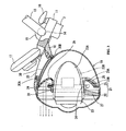
- the head lamp 19 is constructed of a projector lamp 23 as a main light source unit and a plurality of LED units 24, the projector lamp 23 and the plurality of LED units 24 being stored in a lamp housing 21.
- the lamp housing 21 is constructed of a front frame 22 made of metal in the shape of a ring (for example, made of aluminum die casting) and a rear cover 25 made of synthetic resin and fixed to the rear side of the front frame 22.
- a transparent plate 26 is fitted in the front opening of the front frame 22, whereas the rear cover 25 is formed in the shape of a cup contracted rearward.
- the rear cover 25 has its nearly entire area formed of transparent material through which the interior structure of the lamp housing 21 can be seen.
- the projector lamp 23 has a nearly cylindrical lamp body 23A arranged along a central axis of the lamp housing 21.
- the projector lamp 23 is of the type in which light from a light source (for example, a xenon lamp, not shown) stored therein is directly projected forward.
- the projector lamp 23 is set for a low beam in this embodiment.
- the projector lamp 23 has many fins 23B arranged on the entire periphery of the outer peripheral surface of the lamp body 23A thereof.
- Each of the fins 23B is arranged in a projecting manner from a position closer to the front end portion of the lamp body 23A to a rear end portion thereof along the front and rear direction.
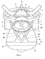
- the lamp body 23A has a total three stays 27 formed at positions closer to the front end of a region in which the fins 23B are arranged on the outer peripheral surface thereof, the three stays 27 being arranged at equal angle intervals so as to extend along a radial direction.
- Each of the stays 27, like the lamp body 23A is integrally formed of metal material having excellent heat radiation and has its tip portion connected to the inner peripheral surface of the front frame 22.
- a fixing ring 28 is arranged rearward of the respective stays 27 so as to surround the entire periphery of the lamp body 23A.
- the fixing ring 28 is connected to the root portions of the respective stays 27. With this, the fixing ring 28 is supported at a position separate outside in a radial direction from the front ends in the radial direction of the fins 23B of the lamp body 23A.
- the fixing ring 28 is formed of metal material having excellent heat radiation in the shape of a ring and has six LED units 24 arranged at equal angle intervals on its rear surface. Each of the LED units 24 has a construction such that an LED chip covered by a cap is placed on a substrate (thermal conductive insulating substrate, for example, made of ceramic).
- the reflector plate 29B has its front side portion curved at a curvature so as to further protrude forward with an increase in a distance from the connection base portion 29A side to the tip side.
- the reflector plate 29B has plural reflective surfaces formed stepwise on the front surface thereof. In this manner, light emitted from the LED unit 24 is reflected by the front surface of the reflector plate 29B corresponding to the LED unit 24 and is passed through the transparent plate 26 and is directed forward of the vehicle.
- the respective LED units 24 are set for a high beam.
- the respective stays 27 are arranged between the adjacent reflectors 29 when the vehicle is viewed from the front. This can make it possible to avoid the trouble that light emitted from the each LED unit 24 is interrupted by the stay 27.
- a mounting part 30 is integrally extended rearward from the upper portion of the front frame 22.
- the mounting part 30 has its width made wide on the side connected to the front frame 22 and narrower toward a rear side thereof.
- the mounting part 30 is formed in a shape curved nearly along the outer surface of the rear cover 25.
- the mounting part 30 has boss portions 30A, 30B arranged on its upper surface, the boss portions 30A, 30B being connected to the lamp holding part 20. As to the respective boss portions 30A, 30B, as shown in Fig.
- boss portions 30A are disposed in parallel in a vehicle width direction in the center portion in the front and rear direction of the mounting part 30, and one boss portion 30B is disposed in the rear end portion of the mounting part 30.
- Each of the boss portions 30A, 30B is formed in the shape of a circular disk and is protruded upward.
- the respective boss portions 30A, 30B can have bolts fastened thereinto from the lamp holding part 20.
- the boss portion 30B arranged in the rear end portion of the mounting part 30 is protruded also to a lower surface side and abuts against the outer surface of the rear cover 25. With this, the mounting part 30 has a clearance held between itself and the outer surface of the rear cover 25, which can enhance a heat radiation function by the mounting part 30.
- the seat 9 has a lamp frame 33 arranged downward thereof in such a way that the lamp frame 33 surrounds the upper portion of a rear fender 32.
- the lamp frame 33 has its entire shape formed nearly in the shape of a letter U and has both end portions connected to the vehicle body frame 1.
- the lamp frame 33 is extended rearward nearly in a horizontal position and has a lamp supporter 34 disposed inside a folding-back portion at the rear end thereof.
- the tail lamp 31 has its rear end portion fixed by this lamp supporter 34 and has its front end side supported in the manner of a cantilever in a state to be separated from the outer surface of a rear fender 32 and in a position projected obliquely forward and upward.
- the tail lamp 31 has a lamp housing 35 elongated in the front and rear direction.
- the lamp housing 35 is formed in the shape of a shallow plate and has a transparent plate 36 fitted on its upper surface.
- the lamp housing 35 has an inner housing 37 disposed therein and has a plurality of support parts 38 disposed inside the inner housing 37, the support parts 38 being disposed respectively between walls opposite in the vehicle width direction at equal intervals in the front and rear direction.
- the support parts 38 except for one support part 38 positioned at the most forward position in the front and rear direction of the vehicle (one support part 38 positioned at the highest position in the direction of height), have LED units 39 fixed thereto, respectively.
- Each of the LED units 39 is fixed in the center portion in the vehicle width direction of each of the support parts 38 in such a way that the light emitted from the LED is directed to a reflector 40 disposed obliquely forward and upward.
- Each of the reflectors 40 except for one reflector 40 positioned at the most rearward position in the front and rear direction of the vehicle (one reflector 40 positioned at the lowest position in the direction of height), is formed nearly over the entire range of the support part 38.
- the inner housing 37 has its inside width made wider toward the front side of the vehicle (toward an upper side in the direction of height), so that also the reflectors 40 have their widths made wider as their heights become larger.
- a single reflector is not arranged as the reflector 40 in the entire area of the inner housing 37, but the plural reflectors 40 are arranged in the divided manner.
- the reflectors 40 arranged in the lamp housing 35 are not made a single member common to all of the LED units 39, but the reflectors 40 are divided into plural members so as to individually correspond to the respective LED units 39.
- the weight of the entire lamp fitting can be reduced.
- the angle of reflection can also be adjusted individually for each reflector 40.
- the tail lamp 31 can be applied to various specifications only by adjusting the angle of reflection of each of the reflectors 40 with the angle of mounting of the tail lamp 31 itself held unchanged as it is.
- the heat generated in the lamp housing 21 is transmitted from the stays 27 to the outer surface of the lamp housing 21 and is transmitted to the handlebar supporting parts via the mounting part 30, so that the heat can effectively be dissipated while the heat is transmitted via a heat transmission path.
Landscapes
- Engineering & Computer Science (AREA)
- Mechanical Engineering (AREA)
- Lighting Device Outwards From Vehicle And Optical Signal (AREA)
- Non-Portable Lighting Devices Or Systems Thereof (AREA)
Claims (10)
- Lampenfassung für ein Fahrzeug, die umfasst:ein Lampengehäuse (21), das so ausgebildet ist, dass es an einer Fahrzeugkarosserie (1) montiert werden kann;eine Vielzahl von Halbleiterlichtemissionsbauelementen (24), die im Lampengehäuse (21) montiert sind;eine Vielzahl von Reflektoren (29), die in Übereinstimmung mit den jeweiligen Halbleiterlichtemissionsbauelementen (24) angeordnet sind, um das daraus emittierte Licht zu reflektieren;eine Hauptlichtquelleneinheit (23), die in einem mittleren Abschnitt des Lampengehäuses (21) angeordnet ist, wobei die Hauptlichtquelleneinheit (23) ausgebildet ist, um ein Lichtverteilungsmuster zu erzeugen, das von dem der jeweiligen Halbleiterlichtemissionsbauelemente (24) abweicht, wobei die Hauptlichtquelleneinheit (23) durch eine Stütze (27) getragen wird, die sich in einer radialen Richtung und nach vom von den Reflektoren (29) zu einer Innenfläche des Lampengehäuses (21) von der Einheit (23) erstreckt.
- Lampenfassung nach Anspruch 1, bei der die jeweiligen Halbleiterlichtemissionsbauelemente (24) und die jeweiligen Reflektoren (29) in radialen Positionen um die Hauptlichtquelleneinheit (23) angeordnet sind.
- Lampenfassung nach Anspruch 1 oder Anspruch 2, bei der die Stütze (27) zwischen benachbarten Reflektoren (29) angeordnet ist.
- Lampenfassung nach einem der vorhergehenden Ansprüche, bei der die Hauptlichtquelleneinheit (23) einen Befestigungsring (28) aufweist, der in einer Position angeordnet ist, die einen äußeren Umfang davon umgibt, wobei der Befestigungsring (28) für ein Montieren der jeweiligen Halbleiterlichtemissionsbauelemente (24) ausgebildet ist.
- Lampenfassung nach Anspruch 4, bei der der Befestigungsring (28) die daran montierten jeweiligen Reflektoren (29) aufweist, wobei die jeweiligen Reflektoren (29) weiter nach hinten als die jeweiligen Halbleiterlichtemissionsbauelemente (24) in einer derartigen Weise angeordnet sind, dass sie den jeweiligen Halbleiterlichtemissionsbauelementen (24) entgegengesetzt sind.
- Lampenfassung nach Anspruch 1 und 4, bei der der Befestigungsring (28) durch die Stütze (27) gestützt wird und separat von einer äußeren Umfangsfläche der Hauptlichtquelleneinheit (23) angeordnet ist.
- Lampenfassung nach einem der vorhergehenden Ansprüche, bei der das Lampengehäuse (21) ein Montageteil (30) aufweist, das so daran befestigt ist, dass es sich vom Fahrzeug nach hinten erstreckt, wobei das Montageteil (30) ausgebildet ist, um das Lampengehäuse (21) zu tragen und einen Abschnitt aufweist, der mit einem Lenkerstützteil (11) für einen Lenker für das Lenken des Fahrzeuges verbunden ist.
- Lampenfassung nach einem der vorhergehenden Ansprüche, bei der die Lampenfassung einen Scheinwerfer (19) für ein Fahrzeug definiert.
- Lampenfassung nach einem der vorhergehenden Ansprüche, bei der die Lampenfassung eine Rückleuchte (31) für ein Fahrzeug definiert.
- Fahrzeug, das eine Lampenfassung nach einem der vorhergehenden Ansprüche umfasst.
Applications Claiming Priority (1)
| Application Number | Priority Date | Filing Date | Title |
|---|---|---|---|
| JP2007260334A JP2009093807A (ja) | 2007-10-03 | 2007-10-03 | 車両用灯具及びそれを備えた車両 |
Publications (3)
| Publication Number | Publication Date |
|---|---|
| EP2052909A2 EP2052909A2 (de) | 2009-04-29 |
| EP2052909A3 EP2052909A3 (de) | 2013-03-06 |
| EP2052909B1 true EP2052909B1 (de) | 2014-05-21 |
Family
ID=40194046
Family Applications (1)
| Application Number | Title | Priority Date | Filing Date |
|---|---|---|---|
| EP08253213.6A Not-in-force EP2052909B1 (de) | 2007-10-03 | 2008-10-02 | Lampenfassung für ein Fahrzeug und Fahrzeug damit |
Country Status (4)
| Country | Link |
|---|---|
| EP (1) | EP2052909B1 (de) |
| JP (1) | JP2009093807A (de) |
| CN (1) | CN101468677B (de) |
| TW (1) | TWI332909B (de) |
Families Citing this family (9)
| Publication number | Priority date | Publication date | Assignee | Title |
|---|---|---|---|---|
| JP5061358B2 (ja) * | 2008-01-31 | 2012-10-31 | 株式会社小糸製作所 | 自動二輪車用前照灯 |
| JP2011014300A (ja) * | 2009-06-30 | 2011-01-20 | Honda Motor Co Ltd | 灯火器 |
| CN102233918B (zh) | 2010-05-07 | 2014-06-11 | 本田技研工业株式会社 | 机动二轮车的前照灯装置 |
| US9318672B2 (en) | 2010-07-08 | 2016-04-19 | Koninklijke Philips N.V. | Leadframe LED lighting assembly |
| FR3022979A1 (fr) * | 2014-06-27 | 2016-01-01 | Valeo Vision | Systeme d'eclairage et/ou de signalisation pour vehicules automobiles |
| CN105066044A (zh) * | 2015-09-06 | 2015-11-18 | 常州市永拓车灯厂 | 一种带led日间行驶灯的摩托车前照灯 |
| WO2017169078A1 (ja) * | 2016-03-31 | 2017-10-05 | 本田技研工業株式会社 | 灯火器装置及び鞍乗型車両 |
| JP6818511B2 (ja) * | 2016-10-27 | 2021-01-20 | スタンレー電気株式会社 | 車両用灯具 |
| JP6967396B2 (ja) * | 2017-08-10 | 2021-11-17 | 株式会社小糸製作所 | 車両用灯具 |
Family Cites Families (8)
| Publication number | Priority date | Publication date | Assignee | Title |
|---|---|---|---|---|
| JP4182600B2 (ja) * | 1999-08-23 | 2008-11-19 | 市光工業株式会社 | Led光源を用いた車両用灯具 |
| US6637921B2 (en) * | 2001-09-28 | 2003-10-28 | Osram Sylvania Inc. | Replaceable LED bulb with interchangeable lens optic |
| DE10160052A1 (de) * | 2001-12-06 | 2003-06-18 | Hella Kg Hueck & Co | Fahrzeugleuchte |
| ES2308164T3 (es) | 2003-05-28 | 2008-12-01 | Volkswagen Ag | Dispositivo de iluminacion para vehiculos con un modulo luminiscente que comprende diodos luminiscentes. |
| DE10336974A1 (de) | 2003-08-12 | 2005-03-10 | Hella Kgaa Hueck & Co | Signalleuchte für Fahrzeuge |
| JP4191651B2 (ja) | 2004-06-24 | 2008-12-03 | 株式会社小糸製作所 | 車両用灯具 |
| DE202004017157U1 (de) * | 2004-11-06 | 2005-02-24 | Maxzone Vehicle Lighting Corp., Fontana | Lichtabgabering für Fahrzeugleuchten |
| JP4606930B2 (ja) * | 2005-04-18 | 2011-01-05 | 本田技研工業株式会社 | 車両用灯火装置 |
-
2007
- 2007-10-03 JP JP2007260334A patent/JP2009093807A/ja active Pending
-
2008
- 2008-09-03 TW TW097133791A patent/TWI332909B/zh not_active IP Right Cessation
- 2008-10-02 EP EP08253213.6A patent/EP2052909B1/de not_active Not-in-force
- 2008-10-06 CN CN2008101619564A patent/CN101468677B/zh not_active Expired - Fee Related
Also Published As
| Publication number | Publication date |
|---|---|
| TWI332909B (en) | 2010-11-11 |
| TW200927534A (en) | 2009-07-01 |
| EP2052909A3 (de) | 2013-03-06 |
| JP2009093807A (ja) | 2009-04-30 |
| EP2052909A2 (de) | 2009-04-29 |
| CN101468677A (zh) | 2009-07-01 |
| CN101468677B (zh) | 2011-08-31 |
Similar Documents
| Publication | Publication Date | Title |
|---|---|---|
| EP2052909B1 (de) | Lampenfassung für ein Fahrzeug und Fahrzeug damit | |
| US20040125610A1 (en) | Apparatus and method for providing a modular vehicle light device | |
| JP2011181314A (ja) | 車両用灯具 | |
| US12326230B2 (en) | Light-emitting module and vehicle | |
| JP2008226707A (ja) | 車両用灯具 | |
| JP2008153108A (ja) | 車両用灯具 | |
| JP2017062929A (ja) | 車両用灯火器 | |
| JP5613022B2 (ja) | 二輪車用前照灯 | |
| JP2007220572A (ja) | 照明装置 | |
| EP2187117B1 (de) | Fahrzeugscheinwerfer | |
| JP5486175B2 (ja) | 尾灯装置 | |
| BR102012004771A2 (pt) | Estrutura de farol para veículo | |
| US20040130901A1 (en) | Tail lamp device for motorcycle | |
| KR20200002499A (ko) | 차량용 램프 | |
| EP2281736B1 (de) | Schlusslicht und Motorfahrrad | |
| JP2014154253A (ja) | 車輌用灯具 | |
| JP2011154912A (ja) | 車両用灯具 | |
| EP3560805B1 (de) | Grätschsitzfahrzeug | |
| US11021202B2 (en) | Position light-integrated blinker apparatus | |
| JP3159322U (ja) | 車両用灯具及びそれを備えた車両 | |
| JP2020098715A (ja) | 車両用灯具 | |
| TWI736322B (zh) | 速克達型機車 | |
| JP5864302B2 (ja) | 自動二輪車のledヘッドライト | |
| JPH0749683Y2 (ja) | 点滅警告装置 | |
| JP7591445B2 (ja) | 車両用灯具 |
Legal Events
| Date | Code | Title | Description |
|---|---|---|---|
| PUAI | Public reference made under article 153(3) epc to a published international application that has entered the european phase |
Free format text: ORIGINAL CODE: 0009012 |
|
| 17P | Request for examination filed |
Effective date: 20081008 |
|
| AK | Designated contracting states |
Kind code of ref document: A2 Designated state(s): AT BE BG CH CY CZ DE DK EE ES FI FR GB GR HR HU IE IS IT LI LT LU LV MC MT NL NO PL PT RO SE SI SK TR |
|
| AX | Request for extension of the european patent |
Extension state: AL BA MK RS |
|
| PUAL | Search report despatched |
Free format text: ORIGINAL CODE: 0009013 |
|
| AK | Designated contracting states |
Kind code of ref document: A3 Designated state(s): AT BE BG CH CY CZ DE DK EE ES FI FR GB GR HR HU IE IS IT LI LT LU LV MC MT NL NO PL PT RO SE SI SK TR |
|
| AX | Request for extension of the european patent |
Extension state: AL BA MK RS |
|
| RIC1 | Information provided on ipc code assigned before grant |
Ipc: F21W 101/027 20060101ALN20130125BHEP Ipc: F21Y 101/02 20060101ALN20130125BHEP Ipc: F21V 7/00 20060101ALI20130125BHEP Ipc: B62J 6/02 20060101ALI20130125BHEP Ipc: B60Q 1/00 20060101AFI20130125BHEP Ipc: F21S 8/12 20060101ALI20130125BHEP |
|
| RBV | Designated contracting states (corrected) |
Designated state(s): AT BE BG CH CY CZ DE DK EE ES FI FR GB GR HR HU IE IS IT LI LT LU LV MC MT NL NO PL PT RO SE SI SK TR |
|
| RBV | Designated contracting states (corrected) |
Designated state(s): AT BE BG CH CY CZ DE DK EE ES FI FR GB GR HR HU IE IS IT LI LT LU LV MC MT NL NO PL PT RO SE SI SK TR |
|
| AKX | Designation fees paid |
Designated state(s): AT BE BG CH CY CZ DE DK EE ES FI FR GB GR HR HU IE IS IT LI LT LU LV MC MT NL NO PL PT RO SE SI SK TR |
|
| GRAP | Despatch of communication of intention to grant a patent |
Free format text: ORIGINAL CODE: EPIDOSNIGR1 |
|
| RIC1 | Information provided on ipc code assigned before grant |
Ipc: F21S 8/12 20060101ALI20140113BHEP Ipc: B60Q 1/00 20060101AFI20140113BHEP Ipc: F21V 7/00 20060101ALI20140113BHEP Ipc: B62J 6/02 20060101ALI20140113BHEP Ipc: F21Y 101/02 20060101ALN20140113BHEP Ipc: F21W 101/027 20060101ALN20140113BHEP |
|
| INTG | Intention to grant announced |
Effective date: 20140217 |
|
| GRAS | Grant fee paid |
Free format text: ORIGINAL CODE: EPIDOSNIGR3 |
|
| GRAA | (expected) grant |
Free format text: ORIGINAL CODE: 0009210 |
|
| AK | Designated contracting states |
Kind code of ref document: B1 Designated state(s): AT BE BG CH CY CZ DE DK EE ES FI FR GB GR HR HU IE IS IT LI LT LU LV MC MT NL NO PL PT RO SE SI SK TR |
|
| REG | Reference to a national code |
Ref country code: GB Ref legal event code: FG4D |
|
| REG | Reference to a national code |
Ref country code: CH Ref legal event code: EP |
|
| REG | Reference to a national code |
Ref country code: AT Ref legal event code: REF Ref document number: 669422 Country of ref document: AT Kind code of ref document: T Effective date: 20140615 |
|
| REG | Reference to a national code |
Ref country code: IE Ref legal event code: FG4D |
|
| REG | Reference to a national code |
Ref country code: DE Ref legal event code: R096 Ref document number: 602008032385 Country of ref document: DE Effective date: 20140703 |
|
| REG | Reference to a national code |
Ref country code: AT Ref legal event code: MK05 Ref document number: 669422 Country of ref document: AT Kind code of ref document: T Effective date: 20140521 Ref country code: NL Ref legal event code: VDEP Effective date: 20140521 |
|
| REG | Reference to a national code |
Ref country code: LT Ref legal event code: MG4D |
|
| PG25 | Lapsed in a contracting state [announced via postgrant information from national office to epo] |
Ref country code: FI Free format text: LAPSE BECAUSE OF FAILURE TO SUBMIT A TRANSLATION OF THE DESCRIPTION OR TO PAY THE FEE WITHIN THE PRESCRIBED TIME-LIMIT Effective date: 20140521 Ref country code: GR Free format text: LAPSE BECAUSE OF FAILURE TO SUBMIT A TRANSLATION OF THE DESCRIPTION OR TO PAY THE FEE WITHIN THE PRESCRIBED TIME-LIMIT Effective date: 20140822 Ref country code: NO Free format text: LAPSE BECAUSE OF FAILURE TO SUBMIT A TRANSLATION OF THE DESCRIPTION OR TO PAY THE FEE WITHIN THE PRESCRIBED TIME-LIMIT Effective date: 20140821 Ref country code: IS Free format text: LAPSE BECAUSE OF FAILURE TO SUBMIT A TRANSLATION OF THE DESCRIPTION OR TO PAY THE FEE WITHIN THE PRESCRIBED TIME-LIMIT Effective date: 20140921 Ref country code: LT Free format text: LAPSE BECAUSE OF FAILURE TO SUBMIT A TRANSLATION OF THE DESCRIPTION OR TO PAY THE FEE WITHIN THE PRESCRIBED TIME-LIMIT Effective date: 20140521 |
|
| PG25 | Lapsed in a contracting state [announced via postgrant information from national office to epo] |
Ref country code: AT Free format text: LAPSE BECAUSE OF FAILURE TO SUBMIT A TRANSLATION OF THE DESCRIPTION OR TO PAY THE FEE WITHIN THE PRESCRIBED TIME-LIMIT Effective date: 20140521 Ref country code: SE Free format text: LAPSE BECAUSE OF FAILURE TO SUBMIT A TRANSLATION OF THE DESCRIPTION OR TO PAY THE FEE WITHIN THE PRESCRIBED TIME-LIMIT Effective date: 20140521 Ref country code: PL Free format text: LAPSE BECAUSE OF FAILURE TO SUBMIT A TRANSLATION OF THE DESCRIPTION OR TO PAY THE FEE WITHIN THE PRESCRIBED TIME-LIMIT Effective date: 20140521 Ref country code: ES Free format text: LAPSE BECAUSE OF FAILURE TO SUBMIT A TRANSLATION OF THE DESCRIPTION OR TO PAY THE FEE WITHIN THE PRESCRIBED TIME-LIMIT Effective date: 20140521 Ref country code: HR Free format text: LAPSE BECAUSE OF FAILURE TO SUBMIT A TRANSLATION OF THE DESCRIPTION OR TO PAY THE FEE WITHIN THE PRESCRIBED TIME-LIMIT Effective date: 20140521 Ref country code: LV Free format text: LAPSE BECAUSE OF FAILURE TO SUBMIT A TRANSLATION OF THE DESCRIPTION OR TO PAY THE FEE WITHIN THE PRESCRIBED TIME-LIMIT Effective date: 20140521 |
|
| PG25 | Lapsed in a contracting state [announced via postgrant information from national office to epo] |
Ref country code: PT Free format text: LAPSE BECAUSE OF FAILURE TO SUBMIT A TRANSLATION OF THE DESCRIPTION OR TO PAY THE FEE WITHIN THE PRESCRIBED TIME-LIMIT Effective date: 20140922 |
|
| PG25 | Lapsed in a contracting state [announced via postgrant information from national office to epo] |
Ref country code: RO Free format text: LAPSE BECAUSE OF FAILURE TO SUBMIT A TRANSLATION OF THE DESCRIPTION OR TO PAY THE FEE WITHIN THE PRESCRIBED TIME-LIMIT Effective date: 20140521 Ref country code: CZ Free format text: LAPSE BECAUSE OF FAILURE TO SUBMIT A TRANSLATION OF THE DESCRIPTION OR TO PAY THE FEE WITHIN THE PRESCRIBED TIME-LIMIT Effective date: 20140521 Ref country code: BE Free format text: LAPSE BECAUSE OF FAILURE TO SUBMIT A TRANSLATION OF THE DESCRIPTION OR TO PAY THE FEE WITHIN THE PRESCRIBED TIME-LIMIT Effective date: 20140521 Ref country code: DK Free format text: LAPSE BECAUSE OF FAILURE TO SUBMIT A TRANSLATION OF THE DESCRIPTION OR TO PAY THE FEE WITHIN THE PRESCRIBED TIME-LIMIT Effective date: 20140521 Ref country code: EE Free format text: LAPSE BECAUSE OF FAILURE TO SUBMIT A TRANSLATION OF THE DESCRIPTION OR TO PAY THE FEE WITHIN THE PRESCRIBED TIME-LIMIT Effective date: 20140521 Ref country code: SK Free format text: LAPSE BECAUSE OF FAILURE TO SUBMIT A TRANSLATION OF THE DESCRIPTION OR TO PAY THE FEE WITHIN THE PRESCRIBED TIME-LIMIT Effective date: 20140521 |
|
| REG | Reference to a national code |
Ref country code: DE Ref legal event code: R097 Ref document number: 602008032385 Country of ref document: DE |
|
| PG25 | Lapsed in a contracting state [announced via postgrant information from national office to epo] |
Ref country code: NL Free format text: LAPSE BECAUSE OF FAILURE TO SUBMIT A TRANSLATION OF THE DESCRIPTION OR TO PAY THE FEE WITHIN THE PRESCRIBED TIME-LIMIT Effective date: 20140521 |
|
| PLBE | No opposition filed within time limit |
Free format text: ORIGINAL CODE: 0009261 |
|
| STAA | Information on the status of an ep patent application or granted ep patent |
Free format text: STATUS: NO OPPOSITION FILED WITHIN TIME LIMIT |
|
| 26N | No opposition filed |
Effective date: 20150224 |
|
| PG25 | Lapsed in a contracting state [announced via postgrant information from national office to epo] |
Ref country code: IT Free format text: LAPSE BECAUSE OF FAILURE TO SUBMIT A TRANSLATION OF THE DESCRIPTION OR TO PAY THE FEE WITHIN THE PRESCRIBED TIME-LIMIT Effective date: 20140521 |
|
| PG25 | Lapsed in a contracting state [announced via postgrant information from national office to epo] |
Ref country code: MC Free format text: LAPSE BECAUSE OF FAILURE TO SUBMIT A TRANSLATION OF THE DESCRIPTION OR TO PAY THE FEE WITHIN THE PRESCRIBED TIME-LIMIT Effective date: 20140521 Ref country code: LU Free format text: LAPSE BECAUSE OF FAILURE TO SUBMIT A TRANSLATION OF THE DESCRIPTION OR TO PAY THE FEE WITHIN THE PRESCRIBED TIME-LIMIT Effective date: 20141002 |
|
| REG | Reference to a national code |
Ref country code: CH Ref legal event code: PL |
|
| REG | Reference to a national code |
Ref country code: DE Ref legal event code: R097 Ref document number: 602008032385 Country of ref document: DE Effective date: 20150224 |
|
| REG | Reference to a national code |
Ref country code: IE Ref legal event code: MM4A |
|
| PG25 | Lapsed in a contracting state [announced via postgrant information from national office to epo] |
Ref country code: SI Free format text: LAPSE BECAUSE OF FAILURE TO SUBMIT A TRANSLATION OF THE DESCRIPTION OR TO PAY THE FEE WITHIN THE PRESCRIBED TIME-LIMIT Effective date: 20140521 Ref country code: CH Free format text: LAPSE BECAUSE OF NON-PAYMENT OF DUE FEES Effective date: 20141031 Ref country code: LI Free format text: LAPSE BECAUSE OF NON-PAYMENT OF DUE FEES Effective date: 20141031 |
|
| REG | Reference to a national code |
Ref country code: FR Ref legal event code: PLFP Year of fee payment: 8 |
|
| PG25 | Lapsed in a contracting state [announced via postgrant information from national office to epo] |
Ref country code: IE Free format text: LAPSE BECAUSE OF NON-PAYMENT OF DUE FEES Effective date: 20141002 |
|
| PGFP | Annual fee paid to national office [announced via postgrant information from national office to epo] |
Ref country code: DE Payment date: 20151022 Year of fee payment: 8 Ref country code: GB Payment date: 20151021 Year of fee payment: 8 |
|
| PGFP | Annual fee paid to national office [announced via postgrant information from national office to epo] |
Ref country code: FR Payment date: 20151023 Year of fee payment: 8 |
|
| PG25 | Lapsed in a contracting state [announced via postgrant information from national office to epo] |
Ref country code: BG Free format text: LAPSE BECAUSE OF FAILURE TO SUBMIT A TRANSLATION OF THE DESCRIPTION OR TO PAY THE FEE WITHIN THE PRESCRIBED TIME-LIMIT Effective date: 20140521 |
|
| PG25 | Lapsed in a contracting state [announced via postgrant information from national office to epo] |
Ref country code: CY Free format text: LAPSE BECAUSE OF FAILURE TO SUBMIT A TRANSLATION OF THE DESCRIPTION OR TO PAY THE FEE WITHIN THE PRESCRIBED TIME-LIMIT Effective date: 20140521 |
|
| PG25 | Lapsed in a contracting state [announced via postgrant information from national office to epo] |
Ref country code: TR Free format text: LAPSE BECAUSE OF FAILURE TO SUBMIT A TRANSLATION OF THE DESCRIPTION OR TO PAY THE FEE WITHIN THE PRESCRIBED TIME-LIMIT Effective date: 20140521 Ref country code: HU Free format text: LAPSE BECAUSE OF FAILURE TO SUBMIT A TRANSLATION OF THE DESCRIPTION OR TO PAY THE FEE WITHIN THE PRESCRIBED TIME-LIMIT; INVALID AB INITIO Effective date: 20081002 Ref country code: MT Free format text: LAPSE BECAUSE OF FAILURE TO SUBMIT A TRANSLATION OF THE DESCRIPTION OR TO PAY THE FEE WITHIN THE PRESCRIBED TIME-LIMIT Effective date: 20140521 |
|
| REG | Reference to a national code |
Ref country code: DE Ref legal event code: R119 Ref document number: 602008032385 Country of ref document: DE |
|
| GBPC | Gb: european patent ceased through non-payment of renewal fee |
Effective date: 20161002 |
|
| REG | Reference to a national code |
Ref country code: FR Ref legal event code: ST Effective date: 20170630 |
|
| PG25 | Lapsed in a contracting state [announced via postgrant information from national office to epo] |
Ref country code: DE Free format text: LAPSE BECAUSE OF NON-PAYMENT OF DUE FEES Effective date: 20170503 Ref country code: FR Free format text: LAPSE BECAUSE OF NON-PAYMENT OF DUE FEES Effective date: 20161102 Ref country code: GB Free format text: LAPSE BECAUSE OF NON-PAYMENT OF DUE FEES Effective date: 20161002 |