EP2051120A1 - Lens apparatus comprising a focus-state detecting unit - Google Patents
Lens apparatus comprising a focus-state detecting unit Download PDFInfo
- Publication number
- EP2051120A1 EP2051120A1 EP09151453A EP09151453A EP2051120A1 EP 2051120 A1 EP2051120 A1 EP 2051120A1 EP 09151453 A EP09151453 A EP 09151453A EP 09151453 A EP09151453 A EP 09151453A EP 2051120 A1 EP2051120 A1 EP 2051120A1
- Authority
- EP
- European Patent Office
- Prior art keywords
- focus
- unit
- optical system
- image
- magnification
- Prior art date
- Legal status (The legal status is an assumption and is not a legal conclusion. Google has not performed a legal analysis and makes no representation as to the accuracy of the status listed.)
- Withdrawn
Links
- 230000003287 optical effect Effects 0.000 claims abstract description 171
- 238000001514 detection method Methods 0.000 claims abstract description 112
- 238000003384 imaging method Methods 0.000 claims abstract description 13
- 239000004606 Fillers/Extenders Substances 0.000 claims description 9
- 238000003780 insertion Methods 0.000 claims description 7
- 230000037431 insertion Effects 0.000 claims description 7
- 230000014509 gene expression Effects 0.000 description 108
- 239000013256 coordination polymer Substances 0.000 description 6
- 238000000034 method Methods 0.000 description 6
- 238000010977 unit operation Methods 0.000 description 3
- 101100204253 Arabidopsis thaliana STR2 gene Proteins 0.000 description 1
- 101150058910 RDS1 gene Proteins 0.000 description 1
- 101100467906 Rattus norvegicus Rdh16 gene Proteins 0.000 description 1
- 101100219167 Saccharomyces cerevisiae (strain ATCC 204508 / S288c) BUL1 gene Proteins 0.000 description 1
- 238000005516 engineering process Methods 0.000 description 1
- 238000009432 framing Methods 0.000 description 1
- 230000007246 mechanism Effects 0.000 description 1
- 238000012986 modification Methods 0.000 description 1
- 230000004048 modification Effects 0.000 description 1
- 102220047090 rs6152 Human genes 0.000 description 1
Images


Classifications
-
- G—PHYSICS
- G03—PHOTOGRAPHY; CINEMATOGRAPHY; ANALOGOUS TECHNIQUES USING WAVES OTHER THAN OPTICAL WAVES; ELECTROGRAPHY; HOLOGRAPHY
- G03B—APPARATUS OR ARRANGEMENTS FOR TAKING PHOTOGRAPHS OR FOR PROJECTING OR VIEWING THEM; APPARATUS OR ARRANGEMENTS EMPLOYING ANALOGOUS TECHNIQUES USING WAVES OTHER THAN OPTICAL WAVES; ACCESSORIES THEREFOR
- G03B13/00—Viewfinders; Focusing aids for cameras; Means for focusing for cameras; Autofocus systems for cameras
- G03B13/32—Means for focusing
- G03B13/34—Power focusing
- G03B13/36—Autofocus systems
-
- G—PHYSICS
- G02—OPTICS
- G02B—OPTICAL ELEMENTS, SYSTEMS OR APPARATUS
- G02B7/00—Mountings, adjusting means, or light-tight connections, for optical elements
- G02B7/28—Systems for automatic generation of focusing signals
- G02B7/282—Autofocusing of zoom lenses
Definitions
- the present invention relates to a lens apparatus which has a branching optical system, disposed in a light path, and which is used for a focusing operation using light beams that have been branched.
- AF auto-focusing
- a shooting device such as a still camera or a video camera
- lens/image pickup devices having a branching optical system disposed in a light path and having a focus detector disposed in a branching light path are known from Japanese Patent Laid-Open Nos. 55-76312 , 59-128506 , 8-50227 , 9-274130 , 2002-365517 , 2002-365518 , 2002-372661 , 2003-279842 , 2003-279846 , 2003-279847 , and 2003-287673 .
- Image pickup devices which make variable a focus detection area, which is an area where a length is measured when performing a focusing operation, are discussed in Japanese Patent Laid-Open Nos. 7-46455 and 7-191256 .
- the relationship between a focus change amount and a unit operation amount of a focus moving unit have a predetermined relationship.
- the relationship between the focus change amount and the unit operation amount is a predetermined relationship, it is possible to set a position control precision and an operating speed of the focus moving unit on the basis of this relationship, so that focusing can be carried out at a high speed and with high precision.
- a focusing operation for example, a change in focus magnification at an image-pickup side caused by, for example, mounting converter lenses, a change in an image size at an image-pickup element caused by applying the image
- Factors such as a change in the relationship between a focus change amount and a unit operation amount of the focus moving unit (which results from a magnification change) make it difficult to properly set a position control precision and an operating speed of the focus moving unit, thereby preventing focusing from being carried out at high speed and with high precision.
- a user may want to give priority to a T-number at the image pickup side than to focusing precision when shooting a dark object, or to give priority to following of a focus at high speed with respect to a moving object when shooting the moving body, or to give priority to focusing precision than to focusing speed when shooting a stationary object.
- whether the focusing precision, the focusing speed, or the T-number at the image-pickup side is to be given priority changes frequently, thereby preventing proper focusing characteristics from being obtained for the respective shooting conditions.
- the present invention provides a lens apparatus which is suitable for a film camera and a video/broadcasting camera and which can perform a focusing operation at high speed and with high precision.
- a lens apparatus as specified in claims 1 to 3.
- the focusing optical system it is possible to vary or switch the size that can be occupied by a focus detection area in the focusing detector within a predetermined range.
- a lens apparatus as specified in claim 4.
- the focusing optical system it is possible to vary or switch the amount of driving of the focus moving unit with respect to a signal from the focusing detector.
- a lens apparatus as specified in claim 5.
- the focusing optical system it is possible to vary or switch the precision with which the focusing detector detects the focusing state.
- Fig. 1 shows a focusing optical system
- Fig. 2 shows an exemplary disposition of a focus detection area of a focusing detecting element.
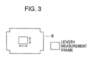
- Fig. 3 shows another exemplary disposition of the focus detection area of the focusing detecting element.
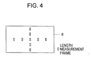
- Fig. 4 shows still another exemplary disposition of the focus detection area of the focusing detecting element.
- Fig. 5 shows still another exemplary disposition of the focus detection area of the focusing detecting element.
- Fig. 6 shows still another exemplary disposition of the focus detection area of the focusing detecting element.
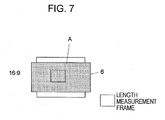
- Fig. 7 shows still another exemplary disposition of the focus detection area of the focusing detecting element.
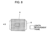
- Fig. 8 shows still another exemplary disposition of the focus detection area of the focusing detecting element.
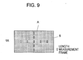
- Fig. 9 shows still another exemplary disposition of the focus detection area of the focusing detecting element.
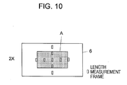
- Fig. 10 shows still another exemplary disposition of the focus detection area of the focusing detecting element.
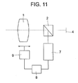
- Fig. 11 shows a structure according to a first embodiment.
- Fig. 12 shows a structure of a camera system including the structure according to the first embodiment.
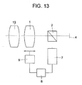
- Fig. 13 shows a structure according to a second embodiment.
- Fig. 14 shows a structure according to a third embodiment.
- Fig. 15 shows a structure according to a fourth embodiment.
- Fig. 16 shows a structure according to a fifth embodiment.
- Fig. 17 shows a structure according to a sixth embodiment.
- Fig. 18 shows a structure according to a seventh embodiment.
- Fig. 19 shows a structure according to an eighth embodiment.
- Fig. 20 shows a structure according to a ninth embodiment.
- Fig. 21 shows a structure according to a tenth embodiment.
- Fig. 22 shows a structure according to an eleventh embodiment.
- Fig. 1 is used to describe a lens apparatus prior to describing the exemplary embodiments.
- a branching optical system 2 which is disposed behind a focus moving unit 1, and an image-pickup-side-portion optical system 3 are successively disposed.
- a camera body 200 comprises an image-pickup element 4, such as a CCD or a CMOS device, that picks up an image formed by the lens apparatus 100.
- a focus-detection-side-portion optical system 5 and a focus-state detecting element 6 are disposed.
- Symbols a to d denote positions where magnification-changing optical systems can be inserted.
- measuring the out-of-focus amount ⁇ sD at the detection side makes it possible to perform a focusing operation at high speed and with high precision as a result of controlling focusing on the basis of Expression (6).
- the ratio RD exceeds the upper limit in Expression (8), the range that can be occupied by the focus detection area lies outside a screen, thereby preventing a focusing operation from being properly carried out.
- the ratio RD becomes less than the lower limit in Expression (8), the range that can be occupied by the focus detection area at the screen is limited, thereby hindering proper framing.
- the driving amount ⁇ XDr' is such that the driving amount ⁇ XDe in Expression (6) becomes different from that before changing the magnification.
- the focus detection area may be disposed by any of the following methods, that is, the method in which the entire range of the focus-state detecting element 6 is used as shown in Fig. 2 , the method in which any range is successively moved and selected as shown in Fig. 3 , and the method in which all or some discrete areas are selected as shown in Fig. 4 .
- the range A that can be occupied by the focus detection area is defined as shown in any one of Figs. 5 to 10
- the movement and selection of the focus detection area in the methods shown in Figs. 5 to 10 are limited to the range A.
- the range A that can be occupied by the focus detection area is given by the length of an image plane at the focus-detection side, unless otherwise specified, the length is any one of a horizontal length, a vertical length, and a diagonal length of the screen, whereas, if specified, the horizontal length and vertical length are separately treated.
- the range A that can be occupied by the focus detection area may be arbitrarily set by a user or may be automatically switched by using a unit for detecting magnification change or mounting or insertion/removal of a magnification-changing unit.
- Fig. 11 shows a structure according to a first embodiment.
- a branching optical system 2 comprising, for example, a half-silvered mirror
- an image-pickup element 4 are disposed behind a moveable focus moving unit 1
- a focus-state detection circuit 7 (incorporating a focus-state detecting element 6) is disposed in the direction in which the branching optical system 2 divides light into the form of branches.
- an output of the focus-state detection circuit 7 is connected to an operational circuit 8, and an output of the operational circuit 8 is connected to a driving unit 9 including an actuator, so as to allow driving of the focus moving unit 1.
- a range A that can be occupied by a focus detection area of the focus-state detection circuit 7.
- a driving amount ⁇ XDr of the focus moving unit 1 which is set by the driving unit 9, with respect to a detection value from the focus-state detection circuit 7.
- a camera system comprises a lens apparatus 11 and a camera body 12.
- the lens apparatus 11 comprises the focus moving unit 1, the branching optical system 2, the focus-state detection circuit 7, the operational circuit 8, and the driving unit 9.
- the camera body 12 comprises the image-pickup element 4 and has the lens apparatus 11 mounted on it.
- Fig. 13 shows a structure according to a second embodiment.
- the structure according to the second embodiment comprises the components according to the first embodiment and a focal-length-changing optical system 13 adjacent or mounted on the focus moving unit 1.
- the focal-length-changing optical system 13 corresponds to the magnification-changing optical system that changes magnification at the position a in Fig. 1 , and FNo of the focus moving unit and a focusing magnification ratio R ⁇ are the same. Therefore, a focus detection precision PDe is the same.
- Ratios RD' before and after the focal-length-changing optical system 13 is attached do not differ from Expression (11), so that a range A is the same.
- a focus change amount ⁇ FD' does not differ from that given by Expression (28), so that a driving amount ⁇ XDr of the focus moving unit 1 is the same.
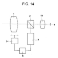
- Fig. 14 shows a structure according to a third embodiment.
- the structure according to the third embodiment comprises the components according to the first embodiment and has a focal-length-changing optical system 14 mounted in a light path between the branching optical system 2 and the image-pickup element 4.
- the focal-length-changing optical system 14 corresponds to the magnification-changing optical system that changes magnification at the position d in Fig. 1 .
- a ratio RD14 that is set when the focal-length-changing optical system 14 is mounted is given by the following Expression (12), as a result of which a focus detectable range on a screen becomes different from that prior to the mounting.
- the focal-length change magnification ⁇ 14 is, for example, 1.4.
- RD 14 ⁇ RD By switching a range that can be occupied by a focus detection area to A1, RD 14 ⁇ RD.
- A1 that can be occupied by the focus detection area on the screen before mounting the focal-length-changing optical system 14 it is desirable that the following Expression (13) be satisfied: 0.9 ⁇ ⁇ 14 ⁇ A ⁇ 1 / A ⁇ 0 ⁇ 1.1
- a focus change amount ⁇ FD' does not differ from that of Expression (28), so that the driving amount ⁇ XDr of the focus moving unit 1 is the same.
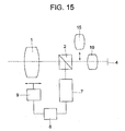
- Fig. 15 shows a structure according to a fourth embodiment.
- the structure according to the fourth embodiment comprises the components according to the first embodiment and has an insertable-and-removable focal-length-changing optical system 15 and a relay lens unit 16 inserted in a light path between the branching optical system 2 and the image-pickup element 4.
- the focal-length-changing optical system 15 corresponds to the magnification-changing optical system that changes magnification at the position c in Fig. 1 .
- a ratio RD that is set when the focal-length-changing optical system 15 is inserted is given by the following Expression (14), as a result of which a range that can be occupied by a focus detection area at a screen becomes different from that prior to the mounting.
- the focal-length change magnification ⁇ 15 of the focal-length-changing optical system 15 is 2.0.
- Fig. 16 shows a structure according to a fifth embodiment.
- the structure according to the fifth embodiment comprises the components according to the first embodiment and has a magnification-changing-and-moving unit 17 inserted between the branching optical system 2 and the focus moving unit 1.
- the magnification-changing-and-moving unit 17 corresponds to the magnification-changing optical system that changes magnification at the position b in Fig. 1 .
- a ratio RD' does not differ from that given by Expression (11), and a range A is the same.
- a magnification changeable range of the magnification-changing-and-moving unit 17 is given by the following Expression (48): 1.0 ⁇ ⁇ 17 ⁇ 2.0
- Fig. 17 shows a structure according to a sixth embodiment.
- the structure according to the sixth embodiment comprises the components according to the first embodiment shown in Fig. 11 and has a magnification-changing-and-moving unit 18 inserted between the branching optical system 2 and the image-pickup element 4.
- the magnification-changing-and-moving unit 18 corresponds to the magnification-changing optical system that changes magnification at the position c in Fig. 1 .
- a ratio RD is given by the following Expression (16), as a result of which a range that can be occupied by a focus detection area on a screen becomes different from that prior to changing magnification:
- a focus change amount ⁇ FD' does not differ from that of Expression (28), so that a driving amount ⁇ XDr of the focus moving unit 1 is the same.
- a magnification changeable range of the magnification-changing-and-moving unit 18 is given by the following Expression (51): 1.08 ⁇ ⁇ 18 ⁇ 2.0
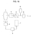
- Fig. 18 shows a structure according to a seventh embodiment.
- the structure according to the seventh embodiment comprises the components according to the fourth embodiment shown in Fig. 15 and has a magnification-changing-and-moving unit 17 inserted in a light path between the branching optical system 2 and the focus moving unit 1 as in the fifth embodiment.
- a magnification changeable range of the magnification-changing-and-moving unit 17 satisfies the following Expression (55): 1.0 ⁇ ⁇ 17 ⁇ 10.0
- the focal-length change magnification ⁇ 15 of the focal-length-changing optical system 15 is 2.0.
- the Expression used to determine a ratio RD15 of a focus detectable range with respect to an image pickup range changes from Expression (14) to Expression (56), which is the same as Expression (45). Since a focus detectable range at the screen is different from that prior to the mounting, A2 is given by Expression (57), which is the same as Expression (46):
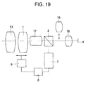
- Fig. 19 shows a structure according to an eighth embodiment.
- the structure according to the eighth embodiment comprises the components according to the seventh embodiment shown in Fig. 18 and has a focal-length-changing optical system 13 mounted at an object side of the focus moving unit 1.
- a focal length change magnification ⁇ 13 of the focal-length-changing optical system 13 is 0.8.
- a range A is the same.
- a driving amount ⁇ XDr is the same.
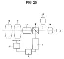
- Fig. 20 shows a structure according to a ninth embodiment.
- the structure according to the ninth embodiment comprises the components according to the eighth embodiment shown in Fig. 19 excluding the relay lens unit 16, and has a focal-length-changing optical system 14 instead of the relay lens unit 16.
- a focal length change magnification ⁇ 14 of the focal-length-changing optical system 14 is 1.4.
- the Expression used to determine a ratio RD14 of a focus detectable range with respect to an image pickup range S changes from Expression (12) to Expression (59).
- Fig. 21 shows a structure according to a tenth embodiment.
- the structure according to the tenth embodiment comprises the components according to the first embodiment, and a stop 19 and an F-number detector 20.
- the stop 19 is disposed between the focus moving unit 1 and the branching optical system 2.
- the F-number detector 20 detects the position of the stop 19.
- An output of the F-number detector 20 and an output of the focus-state detection circuit 7 are connected to the operational circuit 8.
- a range A that can be occupied by a focus detection area and the driving amount ⁇ XDr of the focus moving unit 1 with respect to a detection value from the focus-state detection circuit 7 are variable.
- CP is a constant value, and desirably falls in the range of the following Expression (35): 0.1 ⁇ CP ⁇ 1.0
- FNo of the focusing optical system is detected by the F-number detector 20, and, in accordance with the detection value, the focus detection precision PDe is made variable or is switched.
- a change in the focus detection precision PDe is ideally based on Expression (34), but may be switched in accordance with an FNo range in a prepared table.
- the constant value CP 0.25, and is made to satisfy the condition in Expression (35), so that the focusing can be properly controlled.
- Fig. 22 shows a structure according to an eleventh embodiment.
- the structure according to the eleventh embodiment comprises the components according to the tenth embodiment, and a magnification-changing-and-moving unit 17, an insertable-and-removable focal-length-changing optical system 15, a focal-length-changing optical system 14, and a zoom detector 21.
- the magnification-changing-and-moving unit 17 is inserted between the focus moving unit 1 and the stop 19.
- the focal-length-changing optical system 15 and the focal-length-changing optical system 14 are inserted in a light path between the branching optical system 2 and the image-pickup element 4.
- An output of the zoom detector 21 for the focal-length-changing optical system 17 is connected to the operational circuit 8.
- a magnification change state is detected by the zoom detector 21, and, with a table of maximum FNo values corresponding to the detection values being provided, a focus detection precision PDe is made variable or is switched.
- the method of changing the focus detection precision PDe is the same as that in the tenth embodiment.
- the focal-length-changing optical system 15 corresponds to the magnification-changing optical system that changes magnification at the position c in Fig. 1 .
- the focal-length-changing optical system 14 corresponds to the magnification-changing optical system that changes magnification at the position c in Fig. 1 .
- the focus detection precision PDe changes in proportion to FNo14 ⁇ R ⁇ 142, and satisfies the following Expression (41): 0.9 ⁇ PDe ⁇ 15 ⁇ ⁇ 15 / PDe ⁇ 1.1
- a magnification change ratio ⁇ 17 of the magnification-changing-and-moving unit 17 is given by the following Expression (63), which is the same as Expression (55): 1.0 ⁇ ⁇ 17 ⁇ 10.0
- the focal-length change magnification ⁇ 15 of the focal-length-changing optical system 15 is 2.0.
- CP 0.5, and is made to satisfy the condition in Expression (35), so that focusing is properly controlled.
- the full aperture F-number changes as the magnification changes.
- FNo is 1.4
- FNo is 2.8
- Table 1 shows full aperture F-numbers for respective zoom positions in the eleventh embodiment.
- the ratio RD is given by the following Expression (19), and a range that can be occupied by a focus detection area at the screen is changed:
- the focus detection precision PDe can be arbitrarily switched by a user, so that, depending upon the shooting state, the user can give priority to focusing precision than to focusing speed or to reduce focusing precision and increase focusing speed.
- the focus detection precision PDe is deliberately set relatively high, it is possible to reduce focus hunting resulting from noise of a detection value, when, for example, S/N of the detection value is poor when, for example, an object is dark.
- the range occupied by the focus detection area for focusing, the driving amount of the focus moving unit with respect to the focus-state detection value, and the focus detection precision of the focus-state detection circuit can be set, so that proper focusing can be carried out under various shooting conditions.
Landscapes
- Physics & Mathematics (AREA)
- General Physics & Mathematics (AREA)
- Optics & Photonics (AREA)
- Automatic Focus Adjustment (AREA)
- Lens Barrels (AREA)
- Studio Devices (AREA)
- Focusing (AREA)
- Structure And Mechanism Of Cameras (AREA)
Applications Claiming Priority (2)
| Application Number | Priority Date | Filing Date | Title |
|---|---|---|---|
| JP2005266060A JP4865284B2 (ja) | 2005-09-13 | 2005-09-13 | 合焦結像光学系 |
| EP06254675A EP1762874B1 (en) | 2005-09-13 | 2006-09-07 | Lens apparatus comprising a focus-state detecting unit |
Related Parent Applications (1)
| Application Number | Title | Priority Date | Filing Date |
|---|---|---|---|
| EP06254675A Division EP1762874B1 (en) | 2005-09-13 | 2006-09-07 | Lens apparatus comprising a focus-state detecting unit |
Publications (1)
| Publication Number | Publication Date |
|---|---|
| EP2051120A1 true EP2051120A1 (en) | 2009-04-22 |
Family
ID=37560867
Family Applications (2)
| Application Number | Title | Priority Date | Filing Date |
|---|---|---|---|
| EP06254675A Ceased EP1762874B1 (en) | 2005-09-13 | 2006-09-07 | Lens apparatus comprising a focus-state detecting unit |
| EP09151453A Withdrawn EP2051120A1 (en) | 2005-09-13 | 2006-09-07 | Lens apparatus comprising a focus-state detecting unit |
Family Applications Before (1)
| Application Number | Title | Priority Date | Filing Date |
|---|---|---|---|
| EP06254675A Ceased EP1762874B1 (en) | 2005-09-13 | 2006-09-07 | Lens apparatus comprising a focus-state detecting unit |
Country Status (4)
| Country | Link |
|---|---|
| US (3) | US7532812B2 (enExample) |
| EP (2) | EP1762874B1 (enExample) |
| JP (1) | JP4865284B2 (enExample) |
| DE (1) | DE602006005751D1 (enExample) |
Cited By (1)
| Publication number | Priority date | Publication date | Assignee | Title |
|---|---|---|---|---|
| EP3892955A1 (de) * | 2020-04-09 | 2021-10-13 | Sick Ag | Kamera und verfahren zur erfassung von bilddaten |
Families Citing this family (6)
| Publication number | Priority date | Publication date | Assignee | Title |
|---|---|---|---|---|
| JP4865284B2 (ja) * | 2005-09-13 | 2012-02-01 | キヤノン株式会社 | 合焦結像光学系 |
| EP1925962A1 (en) * | 2006-11-21 | 2008-05-28 | Swiss Medical Technology GmbH | Stereo video microscope system |
| JP2008225239A (ja) * | 2007-03-14 | 2008-09-25 | Fujinon Corp | オートフォーカスシステム |
| JP5031475B2 (ja) * | 2007-07-31 | 2012-09-19 | キヤノン株式会社 | ズームレンズ及びそれを有する撮影システム |
| JP5167365B2 (ja) * | 2010-05-28 | 2013-03-21 | 三菱重工業株式会社 | 監視制御装置及び方法並びにそれを備えたウィンドファーム |
| CN105487196A (zh) * | 2016-01-29 | 2016-04-13 | 福建福光股份有限公司 | 一种用于产线变焦镜头看相的驱动控制盒及其控制方法 |
Citations (19)
| Publication number | Priority date | Publication date | Assignee | Title |
|---|---|---|---|---|
| JPS5576312A (en) | 1978-12-04 | 1980-06-09 | Canon Inc | Focus detecting system of image |
| JPS58219505A (ja) * | 1982-06-14 | 1983-12-21 | Nippon Seimitsu Kogyo Kk | 焦点検出エリアを可変可能な自動焦点装置 |
| JPS59128506A (ja) | 1983-01-14 | 1984-07-24 | Tamuron:Kk | 撮影レンズにおける自動焦点調節機構用光学系 |
| US4812912A (en) * | 1986-05-26 | 1989-03-14 | Minolta Camera Kabushiki Kaisha | Focus detection condition display device for camera |
| US5196877A (en) * | 1988-10-12 | 1993-03-23 | Minolta Camera Kabushiki Kaisha | Viewfinder framing device for zoom lens camera |
| JPH0630317A (ja) * | 1992-07-06 | 1994-02-04 | Canon Inc | 自動焦点調節装置 |
| JPH0746455A (ja) | 1993-05-28 | 1995-02-14 | Canon Inc | ビデオカメラ |
| JPH07191256A (ja) | 1993-12-27 | 1995-07-28 | Canon Inc | 撮像装置 |
| JPH0850227A (ja) | 1994-08-05 | 1996-02-20 | Canon Inc | 色分解光学系及びそれを用いた撮像装置 |
| US5604562A (en) * | 1992-12-03 | 1997-02-18 | Canon Kabushiki Kaisha | Auto-zoom camera |
| JPH09274130A (ja) | 1996-04-08 | 1997-10-21 | Nikon Corp | レンズ鏡筒及びカメラ |
| JP2002365517A (ja) | 2001-06-04 | 2002-12-18 | Fuji Photo Optical Co Ltd | 撮影レンズのピント状態検出装置 |
| JP2002365518A (ja) | 2001-06-04 | 2002-12-18 | Fuji Photo Optical Co Ltd | 撮影レンズのピント状態検出装置 |
| JP2002372661A (ja) | 2001-06-15 | 2002-12-26 | Fuji Photo Optical Co Ltd | 撮影レンズ |
| JP2003279847A (ja) | 2002-03-26 | 2003-10-02 | Fuji Photo Optical Co Ltd | 撮影レンズのピント状態検出装置 |
| JP2003279842A (ja) | 2002-03-22 | 2003-10-02 | Fuji Photo Optical Co Ltd | 撮影レンズのピント状態検出装置 |
| JP2003279846A (ja) | 2002-03-25 | 2003-10-02 | Fuji Photo Optical Co Ltd | 撮影レンズのピント状態検出装置 |
| JP2003287673A (ja) | 2002-03-27 | 2003-10-10 | Fuji Photo Optical Co Ltd | 撮影レンズのピント状態検出装置 |
| JP2004085674A (ja) * | 2002-08-23 | 2004-03-18 | Fuji Photo Optical Co Ltd | オートフォーカスシステム |
Family Cites Families (31)
| Publication number | Priority date | Publication date | Assignee | Title |
|---|---|---|---|---|
| JPS5887510A (ja) * | 1981-11-20 | 1983-05-25 | Nippon Kogaku Kk <Nikon> | カメラ用交換レンズ構体 |
| US4725864A (en) * | 1982-07-17 | 1988-02-16 | Canon Kabushiki Kaisha | Vari-focal camera |
| JPS6053907A (ja) * | 1983-09-02 | 1985-03-28 | Canon Inc | 可変焦点距離レンズ装置 |
| US5055665A (en) * | 1985-10-30 | 1991-10-08 | Canon Kabushiki Kaisha | Focus detecting apparatus jointly employing outputs of plural diverse detectors |
| JP2511409B2 (ja) * | 1986-03-31 | 1996-06-26 | ミノルタ株式会社 | 自動焦点調節装置 |
| US5258798A (en) * | 1987-02-10 | 1993-11-02 | Minolta Camera Kabushiki Kaisha | Camera |
| US4908643A (en) * | 1987-09-21 | 1990-03-13 | Fuji Photo Film Co., Ltd. | Automatic focussing adjusting device |
| JP2754383B2 (ja) * | 1988-02-25 | 1998-05-20 | 株式会社ニコン | 自動焦点調節装置及び撮影システム |
| US5157432A (en) * | 1988-09-09 | 1992-10-20 | Minolta Camera Kabushiki Kaisha | Camera having a zoom lens unit |
| EP0364137A3 (en) * | 1988-09-29 | 1991-07-03 | Nikon Corporation | Automatic focus state detecting apparatus |
| JPH0560967A (ja) * | 1991-08-30 | 1993-03-12 | Canon Inc | カメラ |
| JPH05210039A (ja) * | 1992-01-31 | 1993-08-20 | Nikon Corp | ズームレンズカメラ |
| JP3435580B2 (ja) * | 1993-04-30 | 2003-08-11 | コニカ株式会社 | ズームレンズ鏡胴及びカメラ |
| US6236431B1 (en) * | 1993-05-27 | 2001-05-22 | Canon Kabushiki Kaisha | Video camera apparatus with distance measurement area adjusted based on electronic magnification |
| JPH07281080A (ja) * | 1994-04-06 | 1995-10-27 | Olympus Optical Co Ltd | カメラ |
| JPH0862487A (ja) * | 1994-08-26 | 1996-03-08 | Nikon Corp | 変倍光学系レンズ位置制御装置 |
| US6445416B1 (en) * | 1995-06-30 | 2002-09-03 | Canon Kabushiki Kaisha | Image pickup apparatus having electronic zoom function based on optical zooming focal length variation with time |
| JPH09211308A (ja) * | 1996-02-06 | 1997-08-15 | Eastman Kodak Japan Kk | 自動焦点撮像装置の被写体検出機構 |
| US6377305B2 (en) * | 1997-10-13 | 2002-04-23 | Canon Kabushiki Kaisha | Image sensing apparatus |
| JP4054422B2 (ja) * | 1997-11-13 | 2008-02-27 | キヤノン株式会社 | カメラ及び交換レンズ装置 |
| US6533480B2 (en) | 2000-06-14 | 2003-03-18 | Marc L. Schneider | Adjustable finger stylus |
| US7345706B2 (en) * | 2002-08-23 | 2008-03-18 | Fuji Photo Optical Co., Ltd. | Auto focus system |
| US7317487B2 (en) * | 2003-03-31 | 2008-01-08 | Fujinon Corporation | Compact digital camera with zoom lens system |
| JP2005033508A (ja) * | 2003-07-14 | 2005-02-03 | Minolta Co Ltd | 撮像装置 |
| JP2005156995A (ja) * | 2003-11-26 | 2005-06-16 | Fujinon Corp | オートフォーカスシステム |
| JP2005181469A (ja) | 2003-12-17 | 2005-07-07 | Fujinon Corp | オートフォーカスシステム |
| JP2005326771A (ja) * | 2004-05-17 | 2005-11-24 | Canon Inc | レンズ装置の駆動制御装置 |
| US7469098B2 (en) * | 2004-07-12 | 2008-12-23 | Canon Kabushiki Kaisha | Optical apparatus |
| JP2006243701A (ja) * | 2005-02-07 | 2006-09-14 | Fuji Photo Film Co Ltd | カメラ及びレンズ装置 |
| JP2007079056A (ja) * | 2005-09-13 | 2007-03-29 | Canon Inc | 自動合焦装置及び合焦方法 |
| JP4865284B2 (ja) * | 2005-09-13 | 2012-02-01 | キヤノン株式会社 | 合焦結像光学系 |
-
2005
- 2005-09-13 JP JP2005266060A patent/JP4865284B2/ja not_active Expired - Fee Related
-
2006
- 2006-09-07 DE DE602006005751T patent/DE602006005751D1/de active Active
- 2006-09-07 EP EP06254675A patent/EP1762874B1/en not_active Ceased
- 2006-09-07 EP EP09151453A patent/EP2051120A1/en not_active Withdrawn
- 2006-09-12 US US11/531,021 patent/US7532812B2/en active Active
-
2009
- 2009-04-01 US US12/416,517 patent/US7769283B2/en not_active Expired - Fee Related
- 2009-04-01 US US12/416,511 patent/US8218960B2/en not_active Expired - Fee Related
Patent Citations (19)
| Publication number | Priority date | Publication date | Assignee | Title |
|---|---|---|---|---|
| JPS5576312A (en) | 1978-12-04 | 1980-06-09 | Canon Inc | Focus detecting system of image |
| JPS58219505A (ja) * | 1982-06-14 | 1983-12-21 | Nippon Seimitsu Kogyo Kk | 焦点検出エリアを可変可能な自動焦点装置 |
| JPS59128506A (ja) | 1983-01-14 | 1984-07-24 | Tamuron:Kk | 撮影レンズにおける自動焦点調節機構用光学系 |
| US4812912A (en) * | 1986-05-26 | 1989-03-14 | Minolta Camera Kabushiki Kaisha | Focus detection condition display device for camera |
| US5196877A (en) * | 1988-10-12 | 1993-03-23 | Minolta Camera Kabushiki Kaisha | Viewfinder framing device for zoom lens camera |
| JPH0630317A (ja) * | 1992-07-06 | 1994-02-04 | Canon Inc | 自動焦点調節装置 |
| US5604562A (en) * | 1992-12-03 | 1997-02-18 | Canon Kabushiki Kaisha | Auto-zoom camera |
| JPH0746455A (ja) | 1993-05-28 | 1995-02-14 | Canon Inc | ビデオカメラ |
| JPH07191256A (ja) | 1993-12-27 | 1995-07-28 | Canon Inc | 撮像装置 |
| JPH0850227A (ja) | 1994-08-05 | 1996-02-20 | Canon Inc | 色分解光学系及びそれを用いた撮像装置 |
| JPH09274130A (ja) | 1996-04-08 | 1997-10-21 | Nikon Corp | レンズ鏡筒及びカメラ |
| JP2002365517A (ja) | 2001-06-04 | 2002-12-18 | Fuji Photo Optical Co Ltd | 撮影レンズのピント状態検出装置 |
| JP2002365518A (ja) | 2001-06-04 | 2002-12-18 | Fuji Photo Optical Co Ltd | 撮影レンズのピント状態検出装置 |
| JP2002372661A (ja) | 2001-06-15 | 2002-12-26 | Fuji Photo Optical Co Ltd | 撮影レンズ |
| JP2003279842A (ja) | 2002-03-22 | 2003-10-02 | Fuji Photo Optical Co Ltd | 撮影レンズのピント状態検出装置 |
| JP2003279846A (ja) | 2002-03-25 | 2003-10-02 | Fuji Photo Optical Co Ltd | 撮影レンズのピント状態検出装置 |
| JP2003279847A (ja) | 2002-03-26 | 2003-10-02 | Fuji Photo Optical Co Ltd | 撮影レンズのピント状態検出装置 |
| JP2003287673A (ja) | 2002-03-27 | 2003-10-10 | Fuji Photo Optical Co Ltd | 撮影レンズのピント状態検出装置 |
| JP2004085674A (ja) * | 2002-08-23 | 2004-03-18 | Fuji Photo Optical Co Ltd | オートフォーカスシステム |
Cited By (2)
| Publication number | Priority date | Publication date | Assignee | Title |
|---|---|---|---|---|
| EP3892955A1 (de) * | 2020-04-09 | 2021-10-13 | Sick Ag | Kamera und verfahren zur erfassung von bilddaten |
| US11595741B2 (en) | 2020-04-09 | 2023-02-28 | Sick Ag | Camera and method for detecting image data |
Also Published As
| Publication number | Publication date |
|---|---|
| EP1762874B1 (en) | 2009-03-18 |
| US20090196590A1 (en) | 2009-08-06 |
| JP2007079057A (ja) | 2007-03-29 |
| DE602006005751D1 (de) | 2009-04-30 |
| US20070058963A1 (en) | 2007-03-15 |
| US7532812B2 (en) | 2009-05-12 |
| US8218960B2 (en) | 2012-07-10 |
| EP1762874A3 (en) | 2007-06-06 |
| JP4865284B2 (ja) | 2012-02-01 |
| EP1762874A2 (en) | 2007-03-14 |
| US7769283B2 (en) | 2010-08-03 |
| US20090196591A1 (en) | 2009-08-06 |
Similar Documents
| Publication | Publication Date | Title |
|---|---|---|
| US5867217A (en) | Photographing apparatus and lens position control device | |
| EP1843185B1 (en) | Objective lens with improved focusing operation | |
| KR101395015B1 (ko) | 카메라, 초점 검출방법, 및 제어방법 | |
| US7769283B2 (en) | Lens apparatus wherein focus detection precision is changed in accordance with insertion of an extender optical system into or removal of the extender optical system from the light path of an imaging optical system | |
| EP2993506B1 (en) | Interchangeable lens apparatus, image capturing apparatus and system | |
| JP2008203294A (ja) | 撮像装置 | |
| JP3950685B2 (ja) | ズームレンズおよび撮影システム | |
| JP2009145645A (ja) | 光学機器 | |
| JP2016090911A (ja) | 制御装置、撮像装置、撮像システム、レンズ装置、制御方法、プログラム、および、記憶媒体 | |
| JP2007078833A (ja) | ズームレンズ及びそれを有する撮像装置 | |
| JP4764033B2 (ja) | レンズ駆動装置及び光学機器 | |
| JP2003337277A (ja) | 光学機器 | |
| JP4579572B2 (ja) | 光学機器の駆動制御装置 | |
| US7697041B2 (en) | Zoom lens system and camera using the same | |
| JP3216285B2 (ja) | 光学機器 | |
| EP1530070A1 (en) | Image-taking lens system and image-taking system | |
| JP4795018B2 (ja) | オートフォーカス結像光学系 | |
| JPH0662298A (ja) | カメラ | |
| JPH049911A (ja) | レンズ位置制御装置 | |
| JP2024126983A (ja) | 光学装置、撮像装置および制御方法 | |
| JPH0367209A (ja) | レンズ制御装置 | |
| JPH075356A (ja) | レンズ位置制御装置 | |
| JP2001124981A (ja) | 撮影装置 | |
| JP2011118182A (ja) | レンズ装置及び撮像装置 | |
| JPH041618A (ja) | ビデオカメラ |
Legal Events
| Date | Code | Title | Description |
|---|---|---|---|
| PUAI | Public reference made under article 153(3) epc to a published international application that has entered the european phase |
Free format text: ORIGINAL CODE: 0009012 |
|
| AC | Divisional application: reference to earlier application |
Ref document number: 1762874 Country of ref document: EP Kind code of ref document: P |
|
| AK | Designated contracting states |
Kind code of ref document: A1 Designated state(s): DE FR GB |
|
| 17P | Request for examination filed |
Effective date: 20091022 |
|
| AKX | Designation fees paid |
Designated state(s): DE FR GB |
|
| 17Q | First examination report despatched |
Effective date: 20110627 |
|
| STAA | Information on the status of an ep patent application or granted ep patent |
Free format text: STATUS: THE APPLICATION HAS BEEN WITHDRAWN |
|
| 18W | Application withdrawn |
Effective date: 20190125 |