EP1762874B1 - Lens apparatus comprising a focus-state detecting unit - Google Patents
Lens apparatus comprising a focus-state detecting unit Download PDFInfo
- Publication number
- EP1762874B1 EP1762874B1 EP06254675A EP06254675A EP1762874B1 EP 1762874 B1 EP1762874 B1 EP 1762874B1 EP 06254675 A EP06254675 A EP 06254675A EP 06254675 A EP06254675 A EP 06254675A EP 1762874 B1 EP1762874 B1 EP 1762874B1
- Authority
- EP
- European Patent Office
- Prior art keywords
- focus
- optical system
- magnification
- range
- changing
- Prior art date
- Legal status (The legal status is an assumption and is not a legal conclusion. Google has not performed a legal analysis and makes no representation as to the accuracy of the status listed.)
- Expired - Fee Related
Links
Images


Classifications
-
- G—PHYSICS
- G03—PHOTOGRAPHY; CINEMATOGRAPHY; ANALOGOUS TECHNIQUES USING WAVES OTHER THAN OPTICAL WAVES; ELECTROGRAPHY; HOLOGRAPHY
- G03B—APPARATUS OR ARRANGEMENTS FOR TAKING PHOTOGRAPHS OR FOR PROJECTING OR VIEWING THEM; APPARATUS OR ARRANGEMENTS EMPLOYING ANALOGOUS TECHNIQUES USING WAVES OTHER THAN OPTICAL WAVES; ACCESSORIES THEREFOR
- G03B13/00—Viewfinders; Focusing aids for cameras; Means for focusing for cameras; Autofocus systems for cameras
- G03B13/32—Means for focusing
- G03B13/34—Power focusing
- G03B13/36—Autofocus systems
-
- G—PHYSICS
- G02—OPTICS
- G02B—OPTICAL ELEMENTS, SYSTEMS OR APPARATUS
- G02B7/00—Mountings, adjusting means, or light-tight connections, for optical elements
- G02B7/28—Systems for automatic generation of focusing signals
- G02B7/282—Autofocusing of zoom lenses
Landscapes
- Physics & Mathematics (AREA)
- General Physics & Mathematics (AREA)
- Optics & Photonics (AREA)
- Automatic Focus Adjustment (AREA)
- Lens Barrels (AREA)
- Studio Devices (AREA)
- Focusing (AREA)
- Structure And Mechanism Of Cameras (AREA)
Description
- The present invention relates to a lens apparatus which has a branching optical system, disposed in a light path, and which is used for a focusing operation using light beams that have been branched.
- Various technologies of auto-focusing (AF) in a shooting device, such as a still camera or a video camera, have hitherto been proposed. In particular lens/image pickup devices having a branching optical system disposed in a light path and having a focus detector disposed in a branching light path are known from
Japanese Patent Laid-Open Nos. 55-76312 59-128506 8-50227 9-274130 2002-365517 2002-365518 2002-372661 2003-279842 2003-279846 2003-279847 2003-287673 Japanese Patent Laid-Open Nos. 7-46455 7-191256 - As discussed in
Japanese Patent Laid-Open No. 55-76312 Japanese Patent Laid-Open No. 2003-287673 - Here, it is desirable that the relationship between a focus change amount and a unit operation amount of a focus moving unit have a predetermined relationship. When the relationship between the focus change amount and the unit operation amount is a predetermined relationship, it is possible to set a position control precision and an operating speed of the focus moving unit on the basis of this relationship, so that focusing can be carried out at a high speed and with high precision.
- In a focusing operation, for example, a change in focus magnification at an image-pickup side caused by, for example, mounting converter lenses, a change in an image size at an image-pickup element caused by applying the image -pickup element to a lens-replacement-type image pickup device, and a change in an image pickup range due to a difference between aspect ratios may occur. Therefore, a change may occur in the relationship between the image pickup side and the focus detection side, as a result of which a proper focusing operation cannot be carried out.
- Factors, such as a change in the relationship between a focus change amount and a unit operation amount of the focus moving unit (which results from a magnification change) make it difficult to properly set a position control precision and an operating speed of the focus moving unit, thereby preventing focusing from being carried out at high speed and with high precision.
- Further, for example, a user may want to give priority to a T-number at the image pickup side than to focusing precision when shooting a dark object, or to give priority to following of a focus at high speed with respect to a moving object when shooting the moving body, or to give priority to focusing precision than to focusing speed when shooting a stationary object. In such cases, depending upon shooting conditions, whether the focusing precision, the focusing speed, or the T-number at the image-pickup side is to be given priority changes frequently, thereby preventing proper focusing characteristics from being obtained for the respective shooting conditions.
- In addition,
US 5,196,877 discloses a viewfinder framing device, andJP-A-2004 085674 JP-A-06- 030317 - The present invention provides a lens apparatus which is suitable for a film camera and a video/broadcasting camera and which can perform a focusing operation at high speed and with high precision.
- According to a first aspect of the prevent invention, there is provided a lens apparatus as specified in
claims 1 to 3. In the focusing optical system, it is possible to vary or switch the size that can be occupied by a focus detection area in the focusing detector within a predetermined range. - According to another aspect of the present invention, there is provided an image pick up apparatus as specified in
claim 4. - Further features of the present invention will become apparent from the following description of exemplary embodiments with reference to the attached drawings.
-
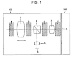
Fig. 1 shows a focusing optical system. -
Fig. 2 shows an exemplary disposition of a focus detection area of a focusing detecting element. -
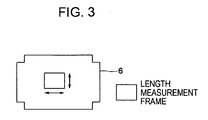
Fig. 3 shows another exemplary disposition of the focus detection area of the focusing detecting element. -
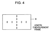
Fig. 4 shows still another exemplary disposition of the focus detection area of the focusing detecting element. -
Fig. 5 shows still another exemplary disposition of the focus detection area of the focusing detecting element. -
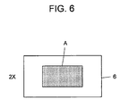
Fig. 6 shows still another exemplary disposition of the focus detection area of the focusing detecting element. -
Fig. 7 shows still another exemplary disposition of the focus detection area of the focusing detecting element. -
Fig. 8 shows still another exemplary disposition of the focus detection area of the focusing detecting element. -
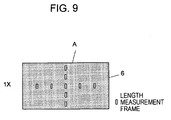
Fig. 9 shows still another exemplary disposition of the focus detection area of the focusing detecting element. -
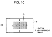
Fig. 10 shows still another exemplary disposition of the focus detection area of the focusing detecting element. -
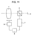
Fig. 11 shows a structure according to a first embodiment. -
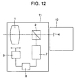
Fig. 12 shows a structure of a camera system including the structure according to the first embodiment. -
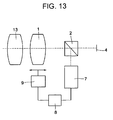
Fig. 13 shows a structure according to a second embodiment. -
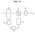
Fig. 14 shows a structure according to a third embodiment. -
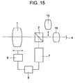
Fig. 15 shows a structure according to a fourth embodiment. -
Fig. 16 shows a structure according to a fifth embodiment. -
Fig. 17 shows a structure according to a sixth embodiment. -
Fig. 18 shows a structure according to a seventh embodiment. -
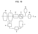
Fig. 19 shows a structure according to an eighth embodiment. -
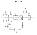
Fig. 20 shows a structure according to a ninth embodiment. -
Fig. 21 shows a structure according to a tenth embodiment. -
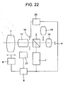
Fig. 22 shows a structure according to an eleventh embodiment. - Exemplary embodiments of the present invention will be described below with reference to the drawings.
-
Fig. 1 is used to describe a lens apparatus prior to describing the exemplary embodiments. InFig. 1 , in alens apparatus 100, a branchingoptical system 2, which is disposed behind afocus moving unit 1, and an image-pickup-side-portionoptical system 3 are successively disposed. Acamera body 200 comprises an image-pickup element 4, such as a CCD or a CMOS device, that picks up an image formed by thelens apparatus 100. In a direction in which the branchingoptical system 2 of thelens apparatus 100 divides light into the form of branches, a focus-detection-side-portionoptical system 5 and a focus-state detecting element 6 are disposed. Symbols a to d denote positions where magnification-changing optical systems can be inserted. A focusing magnification βF of thefocus moving unit 1, a focusing magnification βL of the image-pickup-side-portionoptical system 3, a focusing magnification β5 of the focus-detection-side-portionoptical system 5, a focusing magnification βP at the image-pickup side, and a focusing magnification βD at the detection side have the following relationships of Expressions (1) and (2):

- Therefore, a focusing magnification ratio Rβ of the focusing magnification at the detection side with respect to that at the image-pickup side is given by the following Expression (3), and is set by the portion optical system following the branching optical system 2:

- When there is an out-of-focus amount ΔsP at the image-pickup side, an out-of-focus amount ΔsD at the detection side is proportional to the square of the focusing magnification ratio Rβ, and is given by the following Expression (4):

- Therefore, if the focusing magnification ratio Rβ is known, measuring the out-of-focus amount ΔsD at the detection side makes it possible to determine the out-of-focus amount ΔsP.
- When a focus change amount at the image-pickup side with respect to a unit movement amount of the
focus moving unit 1 is ΔFP, and a focus change amount at the detection side is ΔFD, the focus change amount ΔFD is given by Expression (5), and a movement amount ΔXDe of thefocus moving unit 1 required for a focusing operation is given by Expression (6):

- Accordingly, measuring the out-of-focus amount ΔsD at the detection side makes it possible to perform a focusing operation at high speed and with high precision as a result of controlling focusing on the basis of Expression (6).
- Next, when an image-pickup range (image size) in a diagonal direction of the image-
pickup element 4 is S0, and a range that can be occupied by a focus detection area in a diagonal direction of the focus-state detector 6 is A0, a ratio RD of a focusing detectable range with respect to the image size S0 is given by the following Expression (7):
- Here, it is desirable that the ratio RD satisfy the following Expression (8):

- When the ratio RD exceeds the upper limit in Expression (8), the range that can be occupied by the focus detection area lies outside a screen, thereby preventing a focusing operation from being properly carried out. When the ratio RD becomes less than the lower limit in Expression (8), the range that can be occupied by the focus detection area at the screen is limited, thereby hindering proper framing.
- In
Fig. 1 , in the case in which the magnification-changing mechanisms in the respective positions a to d optically change magnification by, for example, converter lenses, when change magnifications at the positions a to d are βa, βb, βc, and βd, respectively, Expressions (1), (2), and (3) become Expressions (9), (10), and (11), respectively:


- That is, when magnifications are optically changed at the positions c and d that are closer to an image side than the branching optical system, the RD ratio in Expression (7) becomes different from that before changing the magnifications. Therefore, the size of a range A that can be occupied by the focus detection area at the screen is considerably changed.
- The focus change amount ΔFD at the detection side changes due the focusing magnification of the portion optical system that is disposed closer to the focus-
state detecting element 6 than thefocus moving unit 1, and is given by the following Expression (28):
- Therefore, a driving amount ΔXDr' is given by the following Expression (29):

- When the magnification is optically changed at the position b, the driving amount ΔXDr' is such that the driving amount ΔXDe in Expression (6) becomes different from that before changing the magnification.
- The focus detection area may be disposed by any of the following methods, that is, the method in which the entire range of the focus-
state detecting element 6 is used as shown inFig. 2 , the method in which any range is successively moved and selected as shown inFig. 3 , and the method in which all or some discrete areas are selected as shown inFig. 4 . When the range A that can be occupied by the focus detection area is defined as shown in any one ofFigs. 5 to 10 , the movement and selection of the focus detection area in the methods shown inFigs. 5 to 10 are limited to the range A. - When the range A that can be occupied by the focus detection area is given by the length of an image plane at the focus-detection side, unless otherwise specified, the length is any one of a horizontal length, a vertical length, and a diagonal length of the screen, whereas, if specified, the horizontal length and vertical length are separately treated. The range A that can be occupied by the focus detection area may be arbitrarily set by a user or may be automatically switched by using a unit for detecting magnification change or mounting or insertion/removal of a magnification-changing unit.
-
Fig. 11 shows a structure according to an exemplary first embodiment. In the structure, a branching optical system 2 (comprising, for example, a half-silvered mirror) and an image-pickup element 4 are disposed behind a moveablefocus moving unit 1, and a focus-state detection circuit 7 (incorporating a focus-state detecting element 6) is disposed in the direction in which the branchingoptical system 2 divides light into the form of branches. In addition, an output of the focus-state detection circuit 7 is connected to anoperational circuit 8, and an output of theoperational circuit 8 is connected to adriving unit 9 including an actuator, so as to allow driving of thefocus moving unit 1. Here, it is possible to vary a range A that can be occupied by a focus detection area of the focus-state detection circuit 7. In addition, it is possible to vary a driving amount ΔXDr of thefocus moving unit 1, which is set by the drivingunit 9, with respect to a detection value from the focus-state detection circuit 7. - As shown in
Fig. 12 , a camera system comprises alens apparatus 11 and a camera body 12. Thelens apparatus 11 comprises thefocus moving unit 1, the branchingoptical system 2, the focus-state detection circuit 7, theoperational circuit 8, and thedriving unit 9. The camera body 12 comprises the image-pickup element 4 and has thelens apparatus 11 mounted on it. -
Fig. 13 shows a structure according to an exemplary second embodiment. The structure according to the second embodiment comprises the components according to the first embodiment and a focal-length-changingoptical system 13 adjacent or mounted on thefocus moving unit 1. The focal-length-changingoptical system 13 corresponds to the magnification-changing optical system that changes magnification at the position a inFig. 1 , and FNo of the focus moving unit and a focusing magnification ratio Rβ are the same. Therefore, a focus detection precision PDe is the same. - Ratios RD' before and after the focal-length-changing
optical system 13 is attached do not differ from Expression (11), so that a range A is the same. A focus change amount ΔFD' does not differ from that given by Expression (28), so that a driving amount ΔXDr of thefocus moving unit 1 is the same. -
Fig. 14 shows a structure according to a third embodiment. The structure according to the third embodiment comprises the components according to the first embodiment and has a focal-length-changingoptical system 14 mounted in a light path between the branchingoptical system 2 and the image-pickup element 4. The focal-length-changingoptical system 14 corresponds to the magnification-changing optical system that changes magnification at the position d inFig. 1 . When a focal-length change magnification of the focal-length-changingoptical system 14 is β14, a ratio RD14 that is set when the focal-length-changingoptical system 14 is mounted is given by the following Expression (12), as a result of which a focus detectable range on a screen becomes different from that prior to the mounting.
- The focal-length change magnification β14 is, for example, 1.4. By switching a range that can be occupied by a focus detection area to A1,
RD 14 ≅ RD. Here, to maintain the range A1 that can be occupied by the focus detection area on the screen before mounting the focal-length-changingoptical system 14 substantially equal to that after mounting the focal-length-changingoptical system 14, it is desirable that the following Expression (13) be satisfied:
- A focus change amount ΔFD' does not differ from that of Expression (28), so that the driving amount ΔXDr of the
focus moving unit 1 is the same. - When the focal-length-changing
optical system 14 is attached, the Expression used to determine the ratio RD14 of a focus detectable range with respect to an image pickup range S changes from Expression (12) to Expression (42). Since the focus detectable range at the screen is different from that prior to the mounting, A1 is given by Expression (43) in the second embodiment:

- Accordingly, by setting the values of Expression (13) as in the following Expression (44) so that the focus detectable range is switched to A1, it is possible to maintain the focus detectable range before mounting the focal-length-changing
optical system 14 substantially equal to that after mounting the focal-length-changing optical system 14:
-
Fig. 15 shows a structure according to a fourth embodiment. The structure according to the fourth embodiment comprises the components according to the first embodiment and has an insertable-and-removable focal-length-changingoptical system 15 and arelay lens unit 16 inserted in a light path between the branchingoptical system 2 and the image-pickup element 4. The focal-length-changingoptical system 15 corresponds to the magnification-changing optical system that changes magnification at the position c inFig. 1 . When a focal-length change magnification of the focal-length-changingoptical system 15 is β15, a ratio RD that is set when the focal-length-changingoptical system 15 is inserted is given by the following Expression (14), as a result of which a range that can be occupied by a focus detection area at a screen becomes different from that prior to the mounting.
- By switching the range that can be occupied by the focus detection area to A2, RD15 ≅ RD. Here, to maintain the range A2 that can be occupied by the focus detection area on the screen before inserting the focal-length-changing
optical system 15 substantially equal to that after inserting the focal-length-changingoptical system 15, it is desirable that the following Expression (15) be satisfied:
- In the fourth embodiment, the focal-length change magnification β15 of the focal-length-changing
optical system 15 is 2.0. When the focal-length-changingoptical system 15 is inserted, the Expression used to determine the ratio RD15 of a focus detectable range with respect to an image pickup range changes from Expression (14) to Expression (45). Since the focus detectable range at the screen changes - i.e. is different from that prior to the mounting, A2 is given by Expression (46) in the fourth embodiment:

- Accordingly, by setting the values of Expression (15) as in the following Expression (47) so that the focus detectable range is switched to A1, it is possible to maintain the focus detectable range before inserting the focal-length-changing
optical system 15 substantially equal to that after mounting the focal-length-changing optical system 15:
- Driving amounts ΔXDr before and after the insertion or removal of the focal-length-changing
optical system 15 are the same. -
Fig. 16 shows a structure according to an exemplary fifth embodiment. The structure according to the fifth embodiment comprises the components according to the first embodiment and has a magnification-changing-and-movingunit 17 inserted between the branchingoptical system 2 and thefocus moving unit 1. The magnification-changing-and-movingunit 17 corresponds to the magnification-changing optical system that changes magnification at the position b inFig. 1 . A ratio RD' does not differ from that given by Expression (11), and a range A is the same. - When a magnification change ratio of the magnification-changing-and-moving
unit 17 is β17, a driving amount ΔXDr is given by the following Expression (30), causing a focus driving amount per detection value to become different from that prior to changing magnification:
- Since ΔXDr17 is set to a variable value ΔXDr17(17), to maintain focus controlling operations substantially the same, it is desirable that the following Expression (31) be satisfied:

- In the fifth embodiment, a magnification changeable range of the magnification-changing-and-moving
unit 17 is given by the following Expression (48):
- As the magnification is changed by the magnification-changing-and-moving
unit 17, a focus change amount ΔFD changes in accordance with Expression (28), and the driving amount ΔXDr17 of thefocus moving unit 1 is given by the following Expression (49) ("~" stands for "from," and is used with this meaning in some of the other expressions):
- Therefore, by setting the values of Expression (31) as in the following Expression (50) so that the driving amount ΔXDr17(17) is variable, substantially the same focus controlling operations can be carried out before and after changing the magnification by the magnification-changing-and-moving unit 17:

-
Fig. 17 shows a structure according to a sixth embodiment. The structure according to the sixth embodiment comprises the components according to the first embodiment shown inFig. 11 and has a magnification-changing-and-movingunit 18 inserted between the branchingoptical system 2 and the image-pickup element 4. The magnification-changing-and-movingunit 18 corresponds to the magnification-changing optical system that changes magnification at the position c inFig. 1 . When a magnification change ratio of the magnification-changing-and-movingunit 18 is β18, a ratio RD is given by the following Expression (16), as a result of which a range that can be occupied by a focus detection area on a screen becomes different from that prior to changing magnification:
- By setting the range that can be occupied by the focus detection area to a variable value A3(18), RD18 ≅ RD. Here, to maintain the range that can be occupied by the focus detection area on the screen at a substantially equal value, independently of a magnification-changing operation by the magnification-changing-and-moving
unit 18, it is desirable that the following Expression (17) be satisfied:
- A focus change amount ΔFD' does not differ from that of Expression (28), so that a driving amount ΔXDr of the
focus moving unit 1 is the same. - A magnification changeable range of the magnification-changing-and-moving
unit 18 is given by the following Expression (51):
- Since the ratio RD is changed by the magnification change ratio β18, a range A is changed. Due to the magnification change ratio β18 of the magnification-changing-and-moving
unit 18, the Expression used to determine the ratio RD18 of a focus detectable range with respect to an image pickup range S changes from Expression (16) to Expression (52). Since the focus detectable range at the screen is different from that prior to mounting the magnification-changing-and-movingunit 18, it is desirable that Expression (53) be satisfied in the sixth embodiment:

- By setting the values of Expression (17) as in the following Expression (54) so that the focus detectable range is made variable in accordance with A3(18), the focus detectable range is maintained at substantially the same value, independently of a magnification-changing operation by the magnification-changing-and-moving unit 18:

-
Fig. 18 shows a structure according to a seventh embodiment. The structure according to the seventh embodiment comprises the components according to the fourth embodiment shown inFig. 15 and has a magnification-changing-and-movingunit 17 inserted in a light path between the branchingoptical system 2 and thefocus moving unit 1 as in the fifth embodiment. A magnification changeable range of the magnification-changing-and-movingunit 17 satisfies the following Expression (55):
- Since the relationship of a focus detectable range with respect to an image pickup range S does not change regardless of a magnification-changing operation by the magnification-changing-and-moving
unit 17, a range A does not change. - Since, as the magnification is changed by the magnification-changing-and-moving
unit 17, a focus change amount ΔFD changes due to Expression (28), a driving amount ΔXDr' of thefocus moving unit 1 in the seventh embodiment is given by the following Expression (70):
- Therefore, by setting the values of Expression (31) as in the following Expression (71) so that a driving amount ΔXDr17 is made variable, substantially the same focus controlling operations can be carried out before and after changing the magnification by the magnification-changing-and-moving unit 17:

- In the seventh embodiment, the focal-length change magnification β15 of the focal-length-changing
optical system 15 is 2.0. When the focal-length-changingoptical system 15 is inserted, the Expression used to determine a ratio RD15 of a focus detectable range with respect to an image pickup range changes from Expression (14) to Expression (56), which is the same as Expression (45). Since a focus detectable range at the screen is different from that prior to the mounting, A2 is given by Expression (57), which is the same as Expression (46):

- Accordingly, by setting the values of Expression (15) as in the following Expression (58), which is the same as Expression (47), so that the focus detectable range is switched to A2, it is possible to maintain the focus detectable range before mounting the focal-length-changing
optical system 15 substantially equal to that after mounting the focal-length-changing optical system 15:
- Driving amounts ΔXDr before and after the mounting of the focal-length-changing
optical system 15 are the same. -
Fig. 19 shows a structure according to an eighth embodiment. The structure according to the eighth embodiment comprises the components according to the seventh embodiment shown inFig. 18 and has a focal-length-changingoptical system 13 mounted at an object side of thefocus moving unit 1. A focal length change magnification β13 of the focal-length-changingoptical system 13 is 0.8. - Since the relationships of a focus detectable range with respect to an image pickup range S are the same before and after the mounting of the focal-length-changing
optical system 13, a range A is the same. In addition, a driving amount ΔXDr is the same. -
Fig. 20 shows a structure according to a ninth embodiment. The structure according to the ninth embodiment comprises the components according to the eighth embodiment shown inFig. 19 excluding therelay lens unit 16, and has a focal-length-changingoptical system 14 instead of therelay lens unit 16. A focal length change magnification β14 of the focal-length-changingoptical system 14 is 1.4. When the focal-length-changingoptical system 14 is mounted, the Expression used to determine a ratio RD14 of a focus detectable range with respect to an image pickup range S changes from Expression (12) to Expression (59). Since a focus detectable range at the screen changes with respect to that prior to the mounting, A1 is given by Expression (60) in the ninth embodiment:

- Accordingly, by setting the values of Expression (13) as in the following Expression (61) so that the focus detectable range is switched to A1, it is possible to maintain the focus detectable range before mounting the focal-length-changing
optical system 14 substantially equal to that after mounting the focal-length-changing optical system 14:
- Driving amounts ΔXDr before and after the mounting of the focal-length-changing
optical system 14 are the same. -
Fig. 21 shows a structure according to an exemplary tenth embodiment. The structure according to the tenth embodiment comprises the components according to the first embodiment, and astop 19 and an F-number detector 20. Thestop 19 is disposed between thefocus moving unit 1 and the branchingoptical system 2. The F-number detector 20 detects the position of thestop 19. An output of the F-number detector 20 and an output of the focus-state detection circuit 7 are connected to theoperational circuit 8. In the tenth embodiment, a range A that can be occupied by a focus detection area and the driving amount ΔXDr of thefocus moving unit 1 with respect to a detection value from the focus-state detection circuit 7 are variable. - To increase the precision with which focusing is carried out, in general, it is necessary to set the signal-to-noise ratio (S/N) of a signal from the focus-
state detection circuit 7 to a proper value for realizing a precise detecting operation. Therefore, it becomes necessary for an exposure amount used for the detecting operation to be large. Therefore, focusing speed is reduced, or a ratio between light quantities of branched light beams is required at a detection side, thereby reducing light quantity at an image pickup side. - To precisely carry out a focus controlling operation, it becomes necessary to reduce driving speed of the
focus moving unit 1, thereby reducing focusing speed. When a minimum circle of confusion with respect to the image-pickup element 4 is δ, and a diaphragm stop value (F number) of a focusing optical system is FNo, a focal depth d at the image pickup side is given by the following Expression (32):
- The relationship between a required focusing precision P at the image pickup side and a focus detection precision PDe at the detection side is represented by the following Expression (33):

- When the focus precision P is set as a value that is proportional to the focal depth d, the focus detection precision PDe allows a proper focusing precision and a proper focusing speed to be achieved due to the following Expression (34):

- Here, CP is a constant value, and desirably falls in the range of the following Expression (35):

- In the tenth embodiment, FNo of the focusing optical system is detected by the F-
number detector 20, and, in accordance with the detection value, the focus detection precision PDe is made variable or is switched. A change in the focus detection precision PDe is ideally based on Expression (34), but may be switched in accordance with an FNo range in a prepared table. - In the tenth embodiment, δ = 0.01 mm and Rβ = 1.0. The constant value CP = 0.25, and is made to satisfy the condition in Expression (35), so that the focusing can be properly controlled. In addition, in the tenth embodiment, in accordance with the FNo detected by the F-
number detector 20, the focus detection precision PDe of the focus-state detection circuit 7 is varied by the following Expression (62):
- This causes a proper focusing precision and a proper focusing speed to be achieved in accordance with FNo.
-
Fig. 22 shows a structure according to an eleventh embodiment. The structure according to the eleventh embodiment comprises the components according to the tenth embodiment, and a magnification-changing-and-movingunit 17, an insertable-and-removable focal-length-changingoptical system 15, a focal-length-changingoptical system 14, and azoom detector 21. The magnification-changing-and-movingunit 17 is inserted between thefocus moving unit 1 and thestop 19. The focal-length-changingoptical system 15 and the focal-length-changingoptical system 14 are inserted in a light path between the branchingoptical system 2 and the image-pickup element 4. An output of thezoom detector 21 for the focal-length-changingoptical system 17 is connected to theoperational circuit 8. - A magnification change state is detected by the
zoom detector 21, and, with a table of maximum FNo values corresponding to the detection values being provided, a focus detection precision PDe is made variable or is switched. The method of changing the focus detection precision PDe is the same as that in the tenth embodiment. - When the focal-length-changing
optical system 15 is inserted or removed, the focus detection precision PDe is switched. F-number (FNo) 15 of a focusing optical system when the focal-length-changingoptical system 15 is inserted is different from the FNo before the insertion, and is given by the following Expression (36):
- The focal-length-changing
optical system 15 corresponds to the magnification-changing optical system that changes magnification at the position c inFig. 1 . A focusing magnification ratio Rβ prior to inserting the focal-length-changingoptical system 15 is given by the following Expression (37):
- Therefore, it is desirable that the focus detection precision PDe change in proportion to FNo15 · Rβ152, and satisfy the following Expression (38):

- When the focal-length-changing
optical system 14 is inserted or removed, the focus detection precision PDe is switched. F-number (FNo) 14 of a focusing optical system when the focal-length-changingoptical system 14 is inserted is different from the FNo before the insertion, and is given by the following Expression (39):
- The focal-length-changing
optical system 14 corresponds to the magnification-changing optical system that changes magnification at the position c inFig. 1 . A focusing magnification ratio Rβ prior to mounting the focal-length-changingoptical system 14 is given by the following Expression (40):
- Therefore, it is desirable that the focus detection precision PDe changes in proportion to FNo14 · Rβ142, and satisfies the following Expression (41):

- In the eleventh embodiment, a magnification change ratio β17 of the magnification-changing-and-moving
unit 17 is given by the following Expression (63), which is the same as Expression (55):
- Since the relationship of a focus detectable range with respect to an image pickup range S does not change regardless of a magnification-changing operation by the magnification-changing-and-moving
unit 17, the range A does not change. - As the magnification is changed by the magnification-changing-and-moving
unit 17, a focus change amount ΔFD changes due to Expression (28). Therefore, in this embodiment, a driving amount ΔXDr is given by the following Expression (64):
- Therefore, by setting the values of Expression (31) as in the following Formula (65) so that the driving amount ΔXDr17 is made variable, substantially the same focus controlling operations can be carried out before and after changing the magnification by the magnification-changing-and-moving unit 17:

- In the eleventh embodiment, the focal-length change magnification β15 of the focal-length-changing
optical system 15 is 2.0. When the focal-length-changingoptical system 15 is inserted, the Expression used to determine a ratio RD15 of a focus detectable range with respect to an image pickup range changes from Expression (14) to Expression (66). Since a focus detectable range at a screen is different from that prior to the mounting, A2 is given by Expression (67) in the eleventh embodiment:

- Accordingly, by setting the values of Expression (15) as in the following Expression (68) so that the focus detectable range is switched to A2, it is possible to maintain the focus detectable range before mounting the focal-length-changing
optical system 15 substantially equal to that after mounting the focal-length-changing optical system 15:
- Driving amounts ΔXDr before and after the mounting of the focal-length-changing
optical system 15 are the same. - In the eleventh embodiment, δ = 0.01 mm and Rβ = 0.5. CP = 0.5, and is made to satisfy the condition in Expression (35), so that focusing is properly controlled. In addition, in the eleventh embodiment, in accordance with a detection value from the F-
number detector 20, the focus detection precision PDe of the focus-state detection circuit 7 is changed on the basis of the following Expression (69):
- In the eleventh embodiment, the full aperture F-number changes as the magnification changes. At a wide-angle end, FNo is 1.4, and, at a telephoto end, FNo is 2.8. Table 1 shows full aperture F-numbers for respective zoom positions in the eleventh embodiment. When the detection value of the F-
number detector 20 is in the range of from 1.4 to 2.8, the detection value from thezoom detector 21 is converted into an F number on the basis of Table 1, and the focus detection precision PDe is changed on the basis of Expression (69). This causes a proper focusing precision and a proper focusing speed to be achieved in accordance with FNo.Table 1 Magnification Change Ratio β17 Full aperture F- number 1 1.4 5 1.4 7 1.96 10 2.8 - By switching the focus-
state detection circuit 7, it is possible to easily switch a range A, the driving amount ΔXDr, and the focus detection precision PDe in accordance with shooting conditions. - When an image-pickup element having an image size S1 that is different from that of an image-
pickup element 4 is used, a magnification ratio βS1 is given by the following Expression (18):
- The ratio RD is given by the following Expression (19), and a range that can be occupied by a focus detection area at the screen is changed:

- Accordingly, with RDS1 ≅ RD as a result of switching the range that can be occupied by the focus detection area when the image-pickup element is used to A4, it is desirable that the following Expression (20) be satisfied in order to keep the range that can be occupied by the focus detection area at the screen when the image-pickup element is used substantially equal to the range that can be occupied by the focus detection area at the screen when the image-
pickup element 4 is used:
- When a horizontal length of the image pickup range or the range that can be occupied by the focus detection area is H and a vertical length thereof is V, an aspect ratio AR is given by the following Expression (21):

- When an aspect ratio of the image-
pickup element 4 is AR0, and an image-pickup element having an aspect ratio AR2 that is different from that of the image-pickup element 4 is used, the following Expressions (22) and (23) are established:

- However, when AR0 = H0/V0 and AR2 = H2/V2, ratios RD in the horizontal direction and vertical direction of the screen are given by the following Expressions (24) and (25), respectively, thereby causing the range that can be occupied by the focus detection area at the screen to change:


- Accordingly, by switching the area that can be occupied by the focus detection area to A5 (A5H, A5V), RDH2 ≅ RD and RDV2 ≅ RD, so that the range that can be occupied by the focus detection area at the screen when the image-pickup element is used is maintained substantially equal to the range that can be occupied by the focus detection area at the screen when the image-
pickup element 4 is used. Therefore, when a horizontal range portion of the range A5 is A5H and a vertical range portion of the range A5 is A5V, it is desirable that the following Expressions (26) and (27) be satisfied:

- According to the present invention, the focus detection precision PDe can be arbitrarily switched by a user, so that, depending upon the shooting state, the user can give priority to focusing precision than to focusing speed or to reduce focusing precision and increase focusing speed. In addition, if the focus detection precision PDe is deliberately set relatively high, it is possible to reduce focus hunting resulting from noise of a detection value, when, for example, S/N of the detection value is poor when, for example, an object is dark.
- According to each of the foregoing embodiments, the range occupied by the focus detection area for focusing, the driving amount of the focus moving unit with respect to the focus-state detection value, and the focus detection precision of the focus-state detection circuit can be set, so that proper focusing can be carried out under various shooting conditions.
- While the present invention has been described with reference to exemplary embodiments, it is to be understood that the invention is not limited to the disclosed exemplary embodiments. The scope of the following claims is to be accorded the broadest interpretation so as to encompass all modifications, equivalent structures and functions.
Claims (4)
- A lens apparatus comprising:an imaging optical system including a focus lens unit (1);a branching optical unit (2) disposed at the image side of the focus lens unit;a focus-state detecting unit (7) including a focus detecting element (6) having a focus detection area that receives light beams from the branching optical unit, the focus-state detecting unit detecting a focus state using the focus detecting element;an actuator (9) that drives the focus lens unit in the optical axis direction of the focus lens unit;a controller (8) that controls the actuator, in accordance with an output from the focus-state detecting unit; andan extender optical system (14, 15) mounted in a light path between the branching optical unit and an image pickup element (4), the extender optical system being insertable into and removable from a light path of the imaging optical system,characterized in that the controller changes the size of the focus detection area of the focus detecting element in accordance with the insertion of the extender optical system into or the removal of the extender optical system from the light path of the imaging optical system, and the following expression is satisfied:

where β represents the magnification change ratio of the extender optical system, A0 represents the range that can be occupied by the focus detection area at the time of the removal of the extender optical system, and A1 represents the range that can be occupied by the focus detection area at the time of the insertion of the extender optical system. - The lens apparatus as claimed in claim 1 in which 1.0 < β < 10.0.
- The lens apparatus according to Claim 1 or 2, wherein the movable image-side optical unit is a zoom optical system (17), and the controller changes the size of the focus detection area of the focus detecting element in accordance with a zoom position of the zoom optical system.
- An image pickup apparatus comprising: a lens apparatus as claimed in any preceding claim and a camera including the image-pickup element (4) that picks up an image from the lens apparatus.
Priority Applications (1)
| Application Number | Priority Date | Filing Date | Title |
|---|---|---|---|
| EP09151453A EP2051120A1 (en) | 2005-09-13 | 2006-09-07 | Lens apparatus comprising a focus-state detecting unit |
Applications Claiming Priority (1)
| Application Number | Priority Date | Filing Date | Title |
|---|---|---|---|
| JP2005266060A JP4865284B2 (en) | 2005-09-13 | 2005-09-13 | Focusing optical system |
Related Child Applications (1)
| Application Number | Title | Priority Date | Filing Date |
|---|---|---|---|
| EP09151453A Division EP2051120A1 (en) | 2005-09-13 | 2006-09-07 | Lens apparatus comprising a focus-state detecting unit |
Publications (3)
| Publication Number | Publication Date |
|---|---|
| EP1762874A2 EP1762874A2 (en) | 2007-03-14 |
| EP1762874A3 EP1762874A3 (en) | 2007-06-06 |
| EP1762874B1 true EP1762874B1 (en) | 2009-03-18 |
Family
ID=37560867
Family Applications (2)
| Application Number | Title | Priority Date | Filing Date |
|---|---|---|---|
| EP09151453A Withdrawn EP2051120A1 (en) | 2005-09-13 | 2006-09-07 | Lens apparatus comprising a focus-state detecting unit |
| EP06254675A Expired - Fee Related EP1762874B1 (en) | 2005-09-13 | 2006-09-07 | Lens apparatus comprising a focus-state detecting unit |
Family Applications Before (1)
| Application Number | Title | Priority Date | Filing Date |
|---|---|---|---|
| EP09151453A Withdrawn EP2051120A1 (en) | 2005-09-13 | 2006-09-07 | Lens apparatus comprising a focus-state detecting unit |
Country Status (4)
| Country | Link |
|---|---|
| US (3) | US7532812B2 (en) |
| EP (2) | EP2051120A1 (en) |
| JP (1) | JP4865284B2 (en) |
| DE (1) | DE602006005751D1 (en) |
Families Citing this family (7)
| Publication number | Priority date | Publication date | Assignee | Title |
|---|---|---|---|---|
| JP4865284B2 (en) * | 2005-09-13 | 2012-02-01 | キヤノン株式会社 | Focusing optical system |
| EP1925962A1 (en) * | 2006-11-21 | 2008-05-28 | Swiss Medical Technology GmbH | Stereo video microscope system |
| JP2008225239A (en) * | 2007-03-14 | 2008-09-25 | Fujinon Corp | Autofocus system |
| JP5031475B2 (en) | 2007-07-31 | 2012-09-19 | キヤノン株式会社 | Zoom lens and photographing system having the same |
| BRPI1004895A2 (en) * | 2010-05-28 | 2017-01-17 | Mitsubishi Heavy Ind Ltd | apparatus and method of monitoring and control and wind power plant equipped with them. |
| CN105487196A (en) * | 2016-01-29 | 2016-04-13 | 福建福光股份有限公司 | Drive control box for production line to check phase of zoom lens and control method thereof |
| DE102020109928B3 (en) * | 2020-04-09 | 2020-12-31 | Sick Ag | Camera and method for capturing image data |
Family Cites Families (50)
| Publication number | Priority date | Publication date | Assignee | Title |
|---|---|---|---|---|
| JPS5576312A (en) | 1978-12-04 | 1980-06-09 | Canon Inc | Focus detecting system of image |
| JPS5887510A (en) * | 1981-11-20 | 1983-05-25 | Nippon Kogaku Kk <Nikon> | Interchangeable lens structure of camera |
| JPS58219505A (en) * | 1982-06-14 | 1983-12-21 | Nippon Seimitsu Kogyo Kk | Automatic focusing device capable of varying area for detecting focus |
| US4725864A (en) * | 1982-07-17 | 1988-02-16 | Canon Kabushiki Kaisha | Vari-focal camera |
| JPS59128506A (en) | 1983-01-14 | 1984-07-24 | Tamuron:Kk | Optical system for automatic focussing mechanism of photographic lens |
| JPS6053907A (en) * | 1983-09-02 | 1985-03-28 | Canon Inc | Lens device with variable focal length |
| US5055665A (en) * | 1985-10-30 | 1991-10-08 | Canon Kabushiki Kaisha | Focus detecting apparatus jointly employing outputs of plural diverse detectors |
| JP2511409B2 (en) * | 1986-03-31 | 1996-06-26 | ミノルタ株式会社 | Automatic focus adjustment device |
| US4812912A (en) * | 1986-05-26 | 1989-03-14 | Minolta Camera Kabushiki Kaisha | Focus detection condition display device for camera |
| US5258798A (en) * | 1987-02-10 | 1993-11-02 | Minolta Camera Kabushiki Kaisha | Camera |
| US4908643A (en) * | 1987-09-21 | 1990-03-13 | Fuji Photo Film Co., Ltd. | Automatic focussing adjusting device |
| JP2754383B2 (en) * | 1988-02-25 | 1998-05-20 | 株式会社ニコン | Automatic focusing device and photographing system |
| US5157432A (en) * | 1988-09-09 | 1992-10-20 | Minolta Camera Kabushiki Kaisha | Camera having a zoom lens unit |
| EP0364137A3 (en) * | 1988-09-29 | 1991-07-03 | Nikon Corporation | Automatic focus state detecting apparatus |
| US5196877A (en) * | 1988-10-12 | 1993-03-23 | Minolta Camera Kabushiki Kaisha | Viewfinder framing device for zoom lens camera |
| JPH0560967A (en) * | 1991-08-30 | 1993-03-12 | Canon Inc | Camera |
| JPH05210039A (en) * | 1992-01-31 | 1993-08-20 | Nikon Corp | Zoom lens camera |
| JP3548184B2 (en) * | 1992-07-06 | 2004-07-28 | キヤノン株式会社 | Focus adjustment device and camera |
| JP3259996B2 (en) * | 1992-12-03 | 2002-02-25 | キヤノン株式会社 | camera |
| JP3435580B2 (en) * | 1993-04-30 | 2003-08-11 | コニカ株式会社 | Zoom lens barrel and camera |
| US6236431B1 (en) * | 1993-05-27 | 2001-05-22 | Canon Kabushiki Kaisha | Video camera apparatus with distance measurement area adjusted based on electronic magnification |
| JPH0746455A (en) | 1993-05-28 | 1995-02-14 | Canon Inc | Video camera |
| JPH07191256A (en) | 1993-12-27 | 1995-07-28 | Canon Inc | Image pickup device |
| JPH07281080A (en) * | 1994-04-06 | 1995-10-27 | Olympus Optical Co Ltd | Camera |
| JP3453433B2 (en) | 1994-08-05 | 2003-10-06 | キヤノン株式会社 | Color separation optical system and imaging apparatus using the same |
| JPH0862487A (en) * | 1994-08-26 | 1996-03-08 | Nikon Corp | Lens position control device in variable power optical system |
| US6445416B1 (en) * | 1995-06-30 | 2002-09-03 | Canon Kabushiki Kaisha | Image pickup apparatus having electronic zoom function based on optical zooming focal length variation with time |
| JPH09211308A (en) * | 1996-02-06 | 1997-08-15 | Eastman Kodak Japan Kk | Mechanism for detecting object of automatic focusing image pickup unit |
| JPH09274130A (en) | 1996-04-08 | 1997-10-21 | Nikon Corp | Lens barrel and camera |
| US6377305B2 (en) * | 1997-10-13 | 2002-04-23 | Canon Kabushiki Kaisha | Image sensing apparatus |
| JP4054422B2 (en) * | 1997-11-13 | 2008-02-27 | キヤノン株式会社 | Camera and interchangeable lens device |
| US6533480B2 (en) | 2000-06-14 | 2003-03-18 | Marc L. Schneider | Adjustable finger stylus |
| JP2002365517A (en) | 2001-06-04 | 2002-12-18 | Fuji Photo Optical Co Ltd | Device for detecting state of focusing of photographic lens |
| JP2002365518A (en) | 2001-06-04 | 2002-12-18 | Fuji Photo Optical Co Ltd | Device for detecting focusing state of photographic lens |
| JP2002372661A (en) | 2001-06-15 | 2002-12-26 | Fuji Photo Optical Co Ltd | Photographic lens |
| JP2003279842A (en) | 2002-03-22 | 2003-10-02 | Fuji Photo Optical Co Ltd | Focus state detector for photographing lens |
| JP2003279846A (en) | 2002-03-25 | 2003-10-02 | Fuji Photo Optical Co Ltd | Focus state detector for photographing lens |
| JP2003279847A (en) | 2002-03-26 | 2003-10-02 | Fuji Photo Optical Co Ltd | Focus state detector for photographing lens |
| JP2003287673A (en) | 2002-03-27 | 2003-10-10 | Fuji Photo Optical Co Ltd | Focusing state detecting device for photographic lens |
| JP2004085674A (en) * | 2002-08-23 | 2004-03-18 | Fuji Photo Optical Co Ltd | Autofocus system |
| US7345706B2 (en) * | 2002-08-23 | 2008-03-18 | Fuji Photo Optical Co., Ltd. | Auto focus system |
| US7317487B2 (en) * | 2003-03-31 | 2008-01-08 | Fujinon Corporation | Compact digital camera with zoom lens system |
| JP2005033508A (en) * | 2003-07-14 | 2005-02-03 | Minolta Co Ltd | Imaging device |
| JP2005156995A (en) * | 2003-11-26 | 2005-06-16 | Fujinon Corp | Autofocus system |
| JP2005181469A (en) | 2003-12-17 | 2005-07-07 | Fujinon Corp | Auto-focus system |
| JP2005326771A (en) * | 2004-05-17 | 2005-11-24 | Canon Inc | Driving control device of lens apparatus |
| US7469098B2 (en) * | 2004-07-12 | 2008-12-23 | Canon Kabushiki Kaisha | Optical apparatus |
| JP2006243701A (en) * | 2005-02-07 | 2006-09-14 | Fuji Photo Film Co Ltd | Camera and lens system |
| JP2007079056A (en) * | 2005-09-13 | 2007-03-29 | Canon Inc | Automatic focusing device and focusing method |
| JP4865284B2 (en) * | 2005-09-13 | 2012-02-01 | キヤノン株式会社 | Focusing optical system |
-
2005
- 2005-09-13 JP JP2005266060A patent/JP4865284B2/en not_active Expired - Fee Related
-
2006
- 2006-09-07 EP EP09151453A patent/EP2051120A1/en not_active Withdrawn
- 2006-09-07 DE DE602006005751T patent/DE602006005751D1/en active Active
- 2006-09-07 EP EP06254675A patent/EP1762874B1/en not_active Expired - Fee Related
- 2006-09-12 US US11/531,021 patent/US7532812B2/en active Active
-
2009
- 2009-04-01 US US12/416,511 patent/US8218960B2/en active Active
- 2009-04-01 US US12/416,517 patent/US7769283B2/en not_active Expired - Fee Related
Also Published As
| Publication number | Publication date |
|---|---|
| US7769283B2 (en) | 2010-08-03 |
| EP2051120A1 (en) | 2009-04-22 |
| DE602006005751D1 (en) | 2009-04-30 |
| US8218960B2 (en) | 2012-07-10 |
| JP4865284B2 (en) | 2012-02-01 |
| US20090196590A1 (en) | 2009-08-06 |
| US20090196591A1 (en) | 2009-08-06 |
| US7532812B2 (en) | 2009-05-12 |
| EP1762874A2 (en) | 2007-03-14 |
| EP1762874A3 (en) | 2007-06-06 |
| US20070058963A1 (en) | 2007-03-15 |
| JP2007079057A (en) | 2007-03-29 |
Similar Documents
| Publication | Publication Date | Title |
|---|---|---|
| US5867217A (en) | Photographing apparatus and lens position control device | |
| EP1762874B1 (en) | Lens apparatus comprising a focus-state detecting unit | |
| JP5031475B2 (en) | Zoom lens and photographing system having the same | |
| US7830422B2 (en) | Lens apparatus, image-pickup apparatus, and image-pickup system | |
| KR101395015B1 (en) | Camera, focus detection method and control method | |
| EP1843185B1 (en) | Objective lens with improved focusing operation | |
| EP2993506B1 (en) | Interchangeable lens apparatus, image capturing apparatus and system | |
| JP2008203294A (en) | Imaging apparatus | |
| JP2007078833A (en) | Zoom lens and imaging apparatus having the same | |
| JP2009115921A (en) | Imaging apparatus | |
| JP3950685B2 (en) | Zoom lens and shooting system | |
| JP2007006357A (en) | Digital camera and digital single-lens reflex camera | |
| US10871626B2 (en) | Lens apparatus, image capturing apparatus, and control method | |
| US7697041B2 (en) | Zoom lens system and camera using the same | |
| JP2003337277A (en) | Optical apparatus | |
| JP2005316032A (en) | Drive controller of optical equipment | |
| EP1530070A1 (en) | Image-taking lens system and image-taking system | |
| JP2001124981A (en) | Photographing device | |
| JP2012048069A (en) | Imaging device | |
| JPH075356A (en) | Lens position controller | |
| JP2000347248A (en) | Finder device for camera | |
| JP2011118182A (en) | Lens device and imaging apparatus | |
| JP2007079058A (en) | Lens device | |
| JPH041618A (en) | Video camera |
Legal Events
| Date | Code | Title | Description |
|---|---|---|---|
| PUAI | Public reference made under article 153(3) epc to a published international application that has entered the european phase |
Free format text: ORIGINAL CODE: 0009012 |
|
| AK | Designated contracting states |
Kind code of ref document: A2 Designated state(s): AT BE BG CH CY CZ DE DK EE ES FI FR GB GR HU IE IS IT LI LT LU LV MC NL PL PT RO SE SI SK TR |
|
| AX | Request for extension of the european patent |
Extension state: AL BA HR MK YU |
|
| PUAL | Search report despatched |
Free format text: ORIGINAL CODE: 0009013 |
|
| AK | Designated contracting states |
Kind code of ref document: A3 Designated state(s): AT BE BG CH CY CZ DE DK EE ES FI FR GB GR HU IE IS IT LI LT LU LV MC NL PL PT RO SE SI SK TR |
|
| AX | Request for extension of the european patent |
Extension state: AL BA HR MK YU |
|
| 17P | Request for examination filed |
Effective date: 20071206 |
|
| AKX | Designation fees paid |
Designated state(s): DE FR GB |
|
| RAP1 | Party data changed (applicant data changed or rights of an application transferred) |
Owner name: CANON KABUSHIKI KAISHA |
|
| GRAP | Despatch of communication of intention to grant a patent |
Free format text: ORIGINAL CODE: EPIDOSNIGR1 |
|
| GRAS | Grant fee paid |
Free format text: ORIGINAL CODE: EPIDOSNIGR3 |
|
| GRAA | (expected) grant |
Free format text: ORIGINAL CODE: 0009210 |
|
| AK | Designated contracting states |
Kind code of ref document: B1 Designated state(s): DE FR GB |
|
| REG | Reference to a national code |
Ref country code: GB Ref legal event code: FG4D |
|
| REF | Corresponds to: |
Ref document number: 602006005751 Country of ref document: DE Date of ref document: 20090430 Kind code of ref document: P |
|
| PLBE | No opposition filed within time limit |
Free format text: ORIGINAL CODE: 0009261 |
|
| STAA | Information on the status of an ep patent application or granted ep patent |
Free format text: STATUS: NO OPPOSITION FILED WITHIN TIME LIMIT |
|
| 26N | No opposition filed |
Effective date: 20091221 |
|
| REG | Reference to a national code |
Ref country code: FR Ref legal event code: PLFP Year of fee payment: 11 |
|
| REG | Reference to a national code |
Ref country code: FR Ref legal event code: PLFP Year of fee payment: 12 |
|
| REG | Reference to a national code |
Ref country code: FR Ref legal event code: PLFP Year of fee payment: 13 |
|
| PGFP | Annual fee paid to national office [announced via postgrant information from national office to epo] |
Ref country code: FR Payment date: 20200928 Year of fee payment: 15 Ref country code: GB Payment date: 20200925 Year of fee payment: 15 |
|
| PGFP | Annual fee paid to national office [announced via postgrant information from national office to epo] |
Ref country code: DE Payment date: 20201127 Year of fee payment: 15 |
|
| REG | Reference to a national code |
Ref country code: DE Ref legal event code: R119 Ref document number: 602006005751 Country of ref document: DE |
|
| GBPC | Gb: european patent ceased through non-payment of renewal fee |
Effective date: 20210907 |
|
| PG25 | Lapsed in a contracting state [announced via postgrant information from national office to epo] |
Ref country code: GB Free format text: LAPSE BECAUSE OF NON-PAYMENT OF DUE FEES Effective date: 20210907 Ref country code: FR Free format text: LAPSE BECAUSE OF NON-PAYMENT OF DUE FEES Effective date: 20210930 Ref country code: DE Free format text: LAPSE BECAUSE OF NON-PAYMENT OF DUE FEES Effective date: 20220401 |