EP2050853B1 - Nähmaschine und Greifer-System für Nähmaschine - Google Patents
Nähmaschine und Greifer-System für Nähmaschine Download PDFInfo
- Publication number
- EP2050853B1 EP2050853B1 EP08016736.4A EP08016736A EP2050853B1 EP 2050853 B1 EP2050853 B1 EP 2050853B1 EP 08016736 A EP08016736 A EP 08016736A EP 2050853 B1 EP2050853 B1 EP 2050853B1
- Authority
- EP
- European Patent Office
- Prior art keywords
- hook
- rotation
- control curve
- sewing machine
- cam
- Prior art date
- Legal status (The legal status is an assumption and is not a legal conclusion. Google has not performed a legal analysis and makes no representation as to the accuracy of the status listed.)
- Active
Links
Images



Classifications
-
- D—TEXTILES; PAPER
- D05—SEWING; EMBROIDERING; TUFTING
- D05B—SEWING
- D05B57/00—Loop takers, e.g. loopers
- D05B57/08—Loop takers, e.g. loopers for lock-stitch sewing machines
- D05B57/10—Shuttles
- D05B57/14—Shuttles with rotary hooks
-
- D—TEXTILES; PAPER
- D05—SEWING; EMBROIDERING; TUFTING
- D05B—SEWING
- D05B57/00—Loop takers, e.g. loopers
- D05B57/08—Loop takers, e.g. loopers for lock-stitch sewing machines
- D05B57/10—Shuttles
- D05B57/14—Shuttles with rotary hooks
- D05B57/143—Vertical axis type
-
- D—TEXTILES; PAPER
- D05—SEWING; EMBROIDERING; TUFTING
- D05B—SEWING
- D05B57/00—Loop takers, e.g. loopers
- D05B57/08—Loop takers, e.g. loopers for lock-stitch sewing machines
-
- D—TEXTILES; PAPER
- D05—SEWING; EMBROIDERING; TUFTING
- D05B—SEWING
- D05B57/00—Loop takers, e.g. loopers
- D05B57/26—Bobbin holders or casings; Bobbin holder or case guards; Bobbin discharge devices
- D05B57/265—Bobbin holders or casings; Bobbin holder or case guards; Bobbin discharge devices for looptakers with vertical axis
-
- D—TEXTILES; PAPER
- D05—SEWING; EMBROIDERING; TUFTING
- D05B—SEWING
- D05B57/00—Loop takers, e.g. loopers
- D05B57/30—Driving-gear for loop takers
- D05B57/36—Driving-gear for loop takers in lock-stitch sewing machines
- D05B57/38—Shuttle drives
Definitions
- the invention relates to a sewing machine according to the preamble of claim 1 and a gripper system for a sewing machine according to the preamble of claim 6.
- a sewing machine according to the preamble of claim 1 and a gripper system for a sewing machine according to the preamble of claim 6 are known from DE 100 25 852 A1 known.
- the DE 100 25 852 A1 shows a horizontal gripper, which has a pivotable about an axis parallel to the gripper drive shaft capsule fan, which rests with a button against a formed on the outer circumference of a control disk control cam.
- the capsule fan has a fan lever which engages with a formed at its free end stop in a recess of the bobbin case and cooperates there with stop surfaces.
- the control cam the movement of the fan lever is controlled so that the speed of the fan lever formed stop is very low when it hits the associated stop surface of the coil capsule.
- control cam is rotatably connected to the transmission shaft and is driven directly by this with respect to the speed of the gripper only half the speed.
- the control cam is on an axial cam as formed frontal curve surface against which the button is pressed. In this embodiment is - as with all other conventional drives - the noise when hitting the holding web of the bobbin capsule on the housing cam very high.
- the invention is therefore based on the object, a sewing machine and a gripper system for a sewing machine in such a way that the noise is significantly reduced.
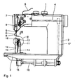
- Fig. 1 illustrated double lockstitch sewing machine has in a conventional manner an upper arm 1, a vertical stand 2 and a lower housing-like base plate 3.
- an arm shaft 4 is mounted, via a needle bar 5 with needle 6 and is driven outgoing.
- a thread lever 7 is driven by it.
- the thread lever 7 is preceded by a needle thread 8 from a thread supply, not shown on the thread lever 7 to the needle 6, a thread tensioning device 9.
- a so-called column sewing machine On the base plate 3 serving as a gripper bearing housing vertical support, a so-called column 10 is attached to the upper end of a gripper bearing 11 is arranged.
- a gripper bearing 11 In this gripper bearing 11 is a vertical gripper 12, that is a about a vertical axis 13 rotatably driven double lockstitch gripper 12, stored.
- a gripper drive shaft 14, which drives the gripper 12 and can be driven about the axis 13, is additionally mounted in an angle gear 15 which is mounted on the base plate 3 and which is designed in the usual way as a bevel gear.
- the toothed belt drive 17 has a gear ratio of 1: 1.
- the angle gear 15 has a gear ratio of 1: 2. This means that the gripper 12 rotates twice when the arm shaft 4 and the transmission shaft 16 makes one revolution.
- a tap hole plate 18 is secured to the column 10 with a tap hole 19.
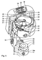
- the pot-shaped gripper 12 has a hook tip 20, which passes directly to the immersed through the needle hole 19 needle 6 and can take the guided in this needle thread 8.
- a coil capsule 21 is arranged, the order the axis 13 is freely rotatable relative to the gripper 12.
- the also upwardly open bobbin capsule 21 has a radially to the axis 13 outwardly and the tap hole plate 18 upwardly projecting retaining web 22 which is rotatably supported only by a few degrees between two formed on the bottom of the needle plate 18 cams 23, 24 is what will be discussed in detail below.
- the air gaps 25, 26, 27 form at a middle position of the holding web 22 a continuous channel.
- a bobbin 29 accommodating a bobbin thread 28, which is held in the bobbin capsule 21 by means of a releasable locking lever 30.
- the coil capsule 21 has at its upper edge on a substantially radially to the axis 13 outwardly projecting fan cam 31 which cooperates with a fan lever 32.
- the fan lever 32 forms an arm of a capsule fan 33.
- Serving as a support for the fan lever 32 capsule fan 33 is designed as a substantially vertical, ie parallel to the axis 13 extending double-armed lever. It has a fan shaft 34 formed by a bolt, which is mounted in the column 10 about an axis 35 perpendicular to the axis 35 and loaded with a return spring 36.
- a button 37 formed by a lever is mounted on the capsule fan 33.
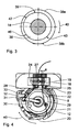
- annular control disk 38 is mounted, which has on its outer circumference a control cam 39 against which the button 37 abuts due to the restoring force of the return spring 36.
- the over the entire circumference of the control disk 38 extending, so closed control cam 39 has different radial distances from the axis 13, so that in one revolution of the gripper drive shaft 14 and thus the gripper 12 of the fan lever 32 back and forth going pivotal movement performs.
- the control disk 38 has a fastening ring 38a, which is fastened adjustably on the gripper drive shaft 14 by means of a clamping screw 38b, which is only indicated.
- the gripper 12 with gripper drive shaft 14, control disk 38 with control cam 39, coil capsule 21 and capsule fan 33 forms a gripper system.
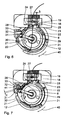
- the basic operation is well known as in capsule fans 33. If the fan lever 32 is not applied to the fan cam 31, then the holding web 22 of the coil capsule 21 is due to the entrainment of the coil capsule 21 by the gripper 12 in the direction of rotation 40 against the first retaining cam 23 at. The second lateral air gap 27 is thereby enlarged, while the first lateral air gap 25 is closed.
- the fan lever 32 is so far pivoted so far due to the corresponding shape of the control cam 39 that between the fan cam 31 and the fan lever 32, a gap 41 of 1 to 1, 5 mm width is formed. In the associated position of the gripper 12 and the bobbin case 21, the reception of a thread loop formed by the needle thread 8 takes place through the hook tip 20.
- the bobbin thread 28 is guided via the locking lever 30 to the tap hole 19.
- the cam 39 also performs a rotational movement in the direction of rotation 40, wherein the rotational speed of the control cam 39 corresponds to the rotational speed of the gripper 12.
- the thread loop of the needle thread 8 is guided in so far known and conventional manner to the largely stationary held coil capsule 21.
- a pivoting movement of the fan lever 32 is initiated by corresponding pivoting of the capsule fan 33 counter to the direction of rotation 40, by appropriate shaping the control cam 39.
- the retaining web 22 is lifted from the first retaining cam 23.
- the holding web 22 is brought approximately in the middle between the two retaining cams 23 and 24, so that the first lateral air gap 25, the upper air gap 26 and the second lateral air gap 27 are continuously open.
- the needle thread loop can slide without resistance through the channel formed by the air gaps 25, 26, 27.
- the capsule fan 33 performs a full stroke every rotation of the gripper 12, although only every second revolution of the gripper 12 is a stitch formation.
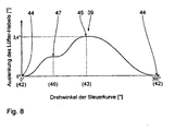
- the control cam 39 has a maximum 42 and this approximately opposite a minimum 43, ie a maximum or minimum distance to the axis 13, on. If the button 37 is guided over the maximum 42, then correspondingly the fan lever 32 is not deflected. He has accordingly Fig. 8 the deflection is zero. This corresponds to a first position 44 of the fan lever 32 according to Fig. 4 and 5 , Accordingly, the coil capsule 21 is pivoted as far as possible against the direction of rotation 40. In other words, this means that the second air gap 27 has its smallest possible width.
- the first air gap 25 has its greatest possible width a of approximately 1.5 mm, where 1.2 ⁇ a ⁇ 1.8 mm.
- This intermediate region 46 corresponds in the development accordingly Fig. 8 the second position 47 marked there.
- This intermediate region 46 starts approximately when the holding web 22 still has a distance b from the first holding cam 23, wherein the following applies to the distance b: 0.05 mm ⁇ b ⁇ 0.15 mm and preferably b ⁇ 0.1 mm.
- this intermediate region 46 is still a pivoting of the probe 37 with correspondingly extremely reduced speed until the rest of the holding web 22 on the first retaining cam 23.
- the further pivoting of the button 37 and thus the fan lever 32, without the coil capsule continues to rotate.
- the gap 41 between the fan lever 32 and the fan cam 31 is thus opened up to the dimension c, where 1.0 mm ⁇ c ⁇ 1.5 mm.
- Fig. 9 to 14 illustrated gripper system is intended for a double lockstitch sewing machine, as it is basically in Fig. 1 is shown. The only difference is that the entire gripper system is built into the base plate 3, as is the case with sewing machines in general is common. This gripper system is thus intended for a so-called flatbed sewing machine.
- the gripper system has a gripper bearing housing 52, in the lower part of which designed as a bevel gear angle reduction gear 15 is arranged. Above the gripper 12, the tap hole plate 18 'is attached.
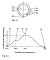
- the control disk 53 with control cam 54 is arranged in this embodiment on the gripper drive shaft 14 'facing bottom 55 of the otherwise unchanged gripper 12.
- the control disk 53 is formed as a flat disk.
- against the also formed on its outer circumference cam 54 is also designed as a feeler lever button 56 of the capsule fan 33 'under the force of the return spring 36' at.
- control disk 53 may be integrally formed with the gripper 12, so be made together with this one piece, as in Fig. 11 is shown. But it can also - as in Fig. 12 indicated - be plugged onto the gripper 12. It is in this case rotatably connected to the gripper 12 by means of a driving pin 57 and positioned in its angular position relative to the gripper 12.
- a plurality of only indicated holes 58 can be formed on the underside 55 of the gripper 12 and / or in the control disk 53 at a small distance from each other, into which the driving pin 57 is inserted, so that an angular adjustment of the control disk 53 and thus the control cam 54 relative to the gripper 12 is reached.
- the thickness d of the control disk 53 and thus of the control cam 54 in the direction of the axis 13 is very small. It is 2.0 mm ⁇ d ⁇ 5 mm.
- For the extent e of trained as a tactile lever button 56 in the direction of the axis 13 is that it must be slightly less than the thickness d. Insofar, 1.5 mm ⁇ e ⁇ 4.0 mm.
- the gripper 12 forms with gripper drive shaft 14 ', SteuerScheibe 53 with cam 54, coil capsule 21 and capsule fan 33' a gripper system.
- the fan lever 32 and the button 37 in opposite directions, that are pivoted oppositely directed is in the embodiment of the Fig. 9 to 14 the fan lever 32 'pivoted in the same direction to the button 56.
- the control cam 54 has a maximum 42 ', a minimum 43' and an intermediate portion 46 ', which results from the same direction pivoting of fan lever 32' and button 56 that when crossing the maximum 42 'with the button 56 of the Fan lever 32 'is deflected maximum. He then has accordingly Fig. 14 the maximum deflection. This corresponds to the third position 45. When passing over the intermediate region 46 ', the second position 47 of the fan lever 32' results. When passing over the minimum 43 'then finally results in the first position 44 of the fan lever 32' with a deflection zero of the fan lever 32 '.
Landscapes
- Engineering & Computer Science (AREA)
- Textile Engineering (AREA)
- Sewing Machines And Sewing (AREA)
Applications Claiming Priority (1)
| Application Number | Priority Date | Filing Date | Title |
|---|---|---|---|
| DE102007050245A DE102007050245A1 (de) | 2007-10-20 | 2007-10-20 | Nähmaschine und Greifer-System für Nähmaschine |
Publications (2)
| Publication Number | Publication Date |
|---|---|
| EP2050853A1 EP2050853A1 (de) | 2009-04-22 |
| EP2050853B1 true EP2050853B1 (de) | 2013-09-18 |
Family
ID=40317105
Family Applications (1)
| Application Number | Title | Priority Date | Filing Date |
|---|---|---|---|
| EP08016736.4A Active EP2050853B1 (de) | 2007-10-20 | 2008-09-24 | Nähmaschine und Greifer-System für Nähmaschine |
Country Status (5)
| Country | Link |
|---|---|
| EP (1) | EP2050853B1 (enExample) |
| JP (1) | JP5337445B2 (enExample) |
| KR (1) | KR101454028B1 (enExample) |
| CN (1) | CN101413189B (enExample) |
| DE (1) | DE102007050245A1 (enExample) |
Families Citing this family (6)
| Publication number | Priority date | Publication date | Assignee | Title |
|---|---|---|---|---|
| TWM366556U (en) * | 2009-03-16 | 2009-10-11 | Chee Siang Ind Co Ltd | Shuttle opening device of sewing machine |
| ITMI20130324A1 (it) * | 2013-03-04 | 2014-09-05 | Cm Cerliani S R L | Crochet rotativo con capsula per macchina per cucire a punto annodato comprendente mezzi per ridurre i giochi tra capsula e cestello e ridurne la rumorosita' |
| CN103966783B (zh) * | 2014-05-13 | 2015-08-26 | 诸暨市新信机电科技有限公司 | 刺绣机旋梭内梭开梭装置 |
| CN104963131B (zh) * | 2014-05-13 | 2017-03-29 | 浙江信胜缝制设备有限公司 | 刺绣机底线断线感应动作机构 |
| CN104988678B (zh) * | 2014-05-13 | 2017-03-29 | 浙江信胜缝制设备有限公司 | 刺绣机旋梭内梭自动开梭机构 |
| DE102022206102A1 (de) | 2022-06-17 | 2023-12-28 | Pfaff Industriesysteme Und Maschinen Gmbh | Nähanlage |
Family Cites Families (9)
| Publication number | Priority date | Publication date | Assignee | Title |
|---|---|---|---|---|
| DE872148C (de) * | 1945-04-18 | 1953-03-30 | Mefina Sa | Rueckhaltevorrichtung fuer die Spulenkapsel |
| GB871101A (en) * | 1959-04-06 | 1961-06-21 | Singer Mfg Co | Bobbin thread case opener mechanism |
| DE3244946C1 (de) * | 1982-12-04 | 1984-04-26 | Pfaff Industriemaschinen Gmbh, 6750 Kaiserslautern | Freiumlaufender Greifer fuer Doppelsteppstichnaehmaschinen |
| DE8437345U1 (de) * | 1984-12-20 | 1986-09-18 | Pfaff Industriemaschinen Gmbh, 6750 Kaiserslautern | Doppelsteppstichnähmaschine mit einem Greifer |
| JP2001300170A (ja) * | 2000-04-27 | 2001-10-30 | Juki Corp | ミシン水平釜のオープナー装置 |
| DE10025852A1 (de) * | 2000-05-25 | 2001-11-29 | Gerd Papajewski | Öffnungsmechanismus für das Spulengehäuse einer Doppelsteppstichnähmaschine |
| DE10025851C1 (de) * | 2000-05-25 | 2002-02-28 | Duerkopp Adler Ag | Nähmaschine |
| JP2002143588A (ja) * | 2000-11-14 | 2002-05-21 | Juki Corp | 水平釜のオープナー駆動機構 |
| DE10261339C1 (de) * | 2002-12-28 | 2003-11-13 | Duerkopp Adler Ag | Nähmaschine |
-
2007
- 2007-10-20 DE DE102007050245A patent/DE102007050245A1/de not_active Withdrawn
-
2008
- 2008-09-24 EP EP08016736.4A patent/EP2050853B1/de active Active
- 2008-10-14 JP JP2008265138A patent/JP5337445B2/ja active Active
- 2008-10-20 KR KR1020080102702A patent/KR101454028B1/ko active Active
- 2008-10-20 CN CN2008101697169A patent/CN101413189B/zh active Active
Also Published As
| Publication number | Publication date |
|---|---|
| DE102007050245A1 (de) | 2009-04-23 |
| KR101454028B1 (ko) | 2014-10-27 |
| KR20090040242A (ko) | 2009-04-23 |
| EP2050853A1 (de) | 2009-04-22 |
| CN101413189B (zh) | 2012-12-12 |
| JP2009101155A (ja) | 2009-05-14 |
| CN101413189A (zh) | 2009-04-22 |
| JP5337445B2 (ja) | 2013-11-06 |
Similar Documents
| Publication | Publication Date | Title |
|---|---|---|
| EP2050853A1 (de) | Nähmaschine und Greifer-System für Nähmaschine | |
| DE10261339C1 (de) | Nähmaschine | |
| DE3039019C2 (de) | Vorrichtung zum Einstellen des Stoffschieberhubes an einer Nähmaschine | |
| EP2050852B1 (de) | Nähmaschine und Greifer-System für Nähmaschine | |
| DE3310132C1 (de) | Fadenbremse für Flachstrickmaschinen | |
| DE1294171B (de) | Greiferantrieb fuer Kettenstichnaehmaschinen | |
| EP2666898A1 (de) | Nähmaschine | |
| DE1131494B (de) | Einrichtung zum automatischen Naehen von Knopfloechern an Zickzacknaehmaschinen | |
| DE19628524A1 (de) | Nähmaschine | |
| DE2616738B2 (de) | Doppelsteppstich-Nähmaschine mit umlaufendem Greifer | |
| DE4326349C2 (de) | Horizontaler umlaufender Greifer für eine Nähmaschine | |
| EP2050851A1 (de) | Nähmaschine und Greifer-System für Nähmaschine | |
| DE10025851C1 (de) | Nähmaschine | |
| DE3340042A1 (de) | Vorrichtung fuer die alternierende druckluftspeisung eines schussfadenmischers an einer schuetzenlosen webmaschine mit pneumatischem schussfadeneintrag | |
| DE614876C (de) | Vorrichtung zur Verhuetung von Fehlstichen an Doppelsteppstich-Naehmaschinen | |
| DE2928257C2 (de) | Schloß für eine Flachstrickmaschine | |
| DE2541378B2 (de) | Vorrichtung zum Abstoppen einer Nähmaschine | |
| DE2205379A1 (de) | Vorrichtung zur automatischen Ausführung von Zierstichen bei Nähmaschinen | |
| DE3117140A1 (de) | Stickmaschine | |
| DE2650352C2 (de) | Nähmaschine mit einem oberhalb der Stichbildestelle angeordneten Greifer | |
| DE2348187C3 (de) | Antriebsvorrichtung für eine Fadenschneidvorrichtung an einer Stichgruppennähmaschine | |
| DE3041780A1 (de) | Naehmaschine mit verstelleinrichtung fuer das nadeldurchgangsloch | |
| DE856987C (de) | Zickzackapparat fuer Naehmaschinen | |
| CH282702A (de) | Häkelmaschine. | |
| DE607326C (de) | Vorrichtung fuer Naehmaschinen zur Erzeugung von Zickzackbewegungen |
Legal Events
| Date | Code | Title | Description |
|---|---|---|---|
| PUAI | Public reference made under article 153(3) epc to a published international application that has entered the european phase |
Free format text: ORIGINAL CODE: 0009012 |
|
| AK | Designated contracting states |
Kind code of ref document: A1 Designated state(s): AT BE BG CH CY CZ DE DK EE ES FI FR GB GR HR HU IE IS IT LI LT LU LV MC MT NL NO PL PT RO SE SI SK TR |
|
| AX | Request for extension of the european patent |
Extension state: AL BA MK RS |
|
| 17P | Request for examination filed |
Effective date: 20091017 |
|
| 17Q | First examination report despatched |
Effective date: 20091118 |
|
| AKX | Designation fees paid |
Designated state(s): CZ DE RO |
|
| GRAP | Despatch of communication of intention to grant a patent |
Free format text: ORIGINAL CODE: EPIDOSNIGR1 |
|
| GRAJ | Information related to disapproval of communication of intention to grant by the applicant or resumption of examination proceedings by the epo deleted |
Free format text: ORIGINAL CODE: EPIDOSDIGR1 |
|
| GRAP | Despatch of communication of intention to grant a patent |
Free format text: ORIGINAL CODE: EPIDOSNIGR1 |
|
| INTG | Intention to grant announced |
Effective date: 20130326 |
|
| GRAP | Despatch of communication of intention to grant a patent |
Free format text: ORIGINAL CODE: EPIDOSNIGR1 |
|
| INTG | Intention to grant announced |
Effective date: 20130430 |
|
| GRAS | Grant fee paid |
Free format text: ORIGINAL CODE: EPIDOSNIGR3 |
|
| GRAA | (expected) grant |
Free format text: ORIGINAL CODE: 0009210 |
|
| AK | Designated contracting states |
Kind code of ref document: B1 Designated state(s): CZ DE RO |
|
| REG | Reference to a national code |
Ref country code: DE Ref legal event code: R096 Ref document number: 502008010668 Country of ref document: DE Effective date: 20131114 |
|
| REG | Reference to a national code |
Ref country code: DE Ref legal event code: R097 Ref document number: 502008010668 Country of ref document: DE |
|
| PLBE | No opposition filed within time limit |
Free format text: ORIGINAL CODE: 0009261 |
|
| STAA | Information on the status of an ep patent application or granted ep patent |
Free format text: STATUS: NO OPPOSITION FILED WITHIN TIME LIMIT |
|
| 26N | No opposition filed |
Effective date: 20140619 |
|
| REG | Reference to a national code |
Ref country code: DE Ref legal event code: R097 Ref document number: 502008010668 Country of ref document: DE Effective date: 20140619 |
|
| REG | Reference to a national code |
Ref country code: RO Ref legal event code: EPE |
|
| P01 | Opt-out of the competence of the unified patent court (upc) registered |
Effective date: 20230510 |
|
| PGFP | Annual fee paid to national office [announced via postgrant information from national office to epo] |
Ref country code: CZ Payment date: 20250912 Year of fee payment: 18 |
|
| PGFP | Annual fee paid to national office [announced via postgrant information from national office to epo] |
Ref country code: RO Payment date: 20250918 Year of fee payment: 18 |
|
| PGFP | Annual fee paid to national office [announced via postgrant information from national office to epo] |
Ref country code: DE Payment date: 20251121 Year of fee payment: 18 |